


Highlights
What are the main findings?
- The reduced-order 3DOF model reproduced the pivot turning trajectory with low prediction error.
- Experimental thrust characterization improved maneuvering prediction accuracy.
What are the implications of the main findings?
- The model provides a practical framework for low-speed AUV maneuvering analysis.
- The proposed approach supports future development of control-oriented AUV simulations.
Abstract
This study presents an experimentally evaluated reduced-order maneuvering framework for a trimaran Autonomous Underwater Vehicle (AUV) by integrating CFD-derived hydrodynamic coefficients with experimentally characterized thruster forces for low-speed pivot turn prediction. Unlike previous studies that primarily focused on hydrodynamic coefficient identification or computational fluid dynamics (CFD)-based hydrodynamic analyses, the proposed approach evaluates the capability of independently derived hydrodynamic parameters to reproduce experimentally observed maneuvering behavior within a computationally efficient three-degrees-of-freedom (3DOF) dynamic model. The maneuvering formulation incorporates nonlinear hydrodynamic derivatives adopted from a previously published virtual Planar Motion Mechanism (PMM) investigation together with experimentally measured thrust characteristics. Numerical simulations were performed in MATLAB using a planar 3DOF maneuvering model, while an experimental evaluation was conducted through a representative pivot turn maneuver in a controlled pool environment using video-based trajectory tracking. The simulated and experimental trajectories exhibited consistent turning behavior, yielding Root Mean Square Error (RMSE) and Mean Absolute Error (MAE) values of 0.0992 m and 0.0905 m, respectively. Although discrepancies were observed in the heading response during the later stages of the maneuver owing to simplified hydrodynamic assumptions and unmodeled nonlinear effects, the proposed framework successfully reproduced the dominant trajectory and yaw characteristics of the investigated maneuver. These results indicate that the proposed reduced-order framework was able to reproduce the investigated low-speed pivot turn maneuver under the validated operating conditions, while broader experimental validation remains necessary to establish its general applicability.
1. Introduction
Autonomous Underwater Vehicles (AUVs) are essential for tasks such as seabed mapping, inspection, and exploration. As missions grow more complex, the need for precise control and maneuverability increases [1]. Operating without real-time human input, AUVs rely on onboard systems to maintain stability and trajectory in dynamic environments. This has led to a strong research focus on hydrodynamic modeling and motion control, particularly in yaw-dominant maneuvers such as turning circles, zigzag tests, and pivot turning, which are widely used to evaluate maneuvering performance and validate control models [2].
In recent years, significant advances have been made in both experimental and simulation-based approaches for analyzing AUV maneuverability. Hydrodynamic coefficients obtained from towing tank experiments, CFD, or PMM tests play a central role in predicting vehicle dynamics with high fidelity [3]. In particular, PMM-based experimental methods have been widely adopted for estimating maneuvering hydrodynamic coefficients of underwater vehicles due to their capability to capture coupled sway and yaw dynamics with high accuracy [3]. CFD-based hydrodynamic investigations have become increasingly important for predicting maneuvering characteristics and evaluating underwater vehicle performance under various operating conditions [4]. Virtual PMM simulations are also widely used to support maneuvering analysis and hydrodynamic evaluation [5]. The presence of appendages may substantially alter the resistance and flow structure around underwater vehicles due to viscous interaction effects and wake formation [6]. Hydrodynamic coefficients are commonly obtained from PMM tests [3]. These hydrodynamic coefficients are commonly implemented in low-order maneuvering models for evaluating the horizontal plane maneuvering performance of underwater vehicles [7]. Similar low-order maneuvering formulations are also widely implemented in MMG-based maneuvering prediction methods [8]. Such models are widely adopted due to their balance between computational efficiency and physical accuracy, particularly for trajectory prediction and control design.
Several studies have explored different AUV configurations to enhance maneuverability. Multi-hull AUV configurations have been investigated to evaluate hydrodynamic characteristics and directional stability under maneuvering conditions [9]. Recent CFD studies have shown that appendages significantly influence the hydrodynamic characteristics of underwater vehicles, particularly in terms of resistance, lift generation, and maneuvering stability. Ahmad et al. [10] demonstrated that appended configurations produce higher resistance and lift compared to bare hull configurations due to flow interaction effects around the control surfaces and sail structures. However, while multi-hull systems offer structural and stability advantages, they introduce complex hydrodynamic interactions between hulls, particularly affecting lateral forces and yaw moments. Recent CFD investigations on multi-hull underwater vehicles demonstrated that hull interaction significantly influences drag distribution and hydrodynamic force characteristics [11]. These interactions significantly influence maneuvering behavior, especially in low-speed conditions and during pivot-type motions, where asymmetric flow separation and cross-flow effects become dominant [5].
Despite these developments, there remains a clear research gap in the maneuvering analysis of three-hull AUVs. Most existing studies focus on either resistance characteristics or straight-line stability, while limited attention has been given to nonlinear maneuvering behavior such as pivot turning. Available hydrodynamic datasets, including those derived from CFD studies [9], primarily provide sway and yaw coefficients without a complete framework for trajectory-level simulation. The absence of surge dynamics and integrated propulsion modeling further limits the applicability of these coefficients in predicting realistic maneuvering paths.
The interaction between thruster configuration and multi-hull geometry has not been thoroughly investigated in the context of maneuvering performance. In practical systems, thrust forces are nonlinear and depend on actuator inputs such as Pulse Width Modulation (PWM), requiring experimental characterization to accurately represent propulsion effects [12]. Without incorporating these effects, simulation models may fail to capture the true dynamic response of the vehicle.
The simulation results are evaluated against experimental data obtained from pool testing. A comparative analysis is conducted using trajectory-based error metrics such as Root Mean Square Error (RMSE), Mean Absolute Error (MAE), and Maximum Error. The objective is to evaluate the capability of the proposed model in reproducing real AUV maneuvering behavior and to identify limitations associated with partial hydrodynamic data and simplified modeling assumptions.
Although previous studies have successfully estimated hydrodynamic coefficients using physical PMM tests or CFD-based virtual PMM simulations, most investigations have focused on conventional single-hull AUVs. The maneuvering characteristics of trimaran AUVs remain insufficiently explored due to their more complex hydrodynamic interactions arising from the multi-hull configuration. Furthermore, previous studies have primarily concentrated on hydrodynamic coefficient identification, with relatively limited attention devoted to experimental validation of reduced-order maneuvering models using actual vehicle trajectories. Consequently, the applicability of CFD-derived hydrodynamic coefficients for predicting the maneuvering performance of trimaran AUVs under realistic operating conditions has not yet been comprehensively demonstrated.
To address these research gaps, this study develops and experimentally evaluates a reduced-order three-degrees-of-freedom maneuvering framework for a trimaran AUV by integrating CFD-derived hydrodynamic coefficients obtained from a virtual PMM investigation with experimentally characterized thruster forces. Unlike previous studies that primarily focused on hydrodynamic coefficient identification or CFD-based hydrodynamic analyses, the present work evaluates the capability of independently derived hydrodynamic parameters to reproduce the experimentally observed pivot turn trajectory under representative low-speed operating conditions. This approach provides initial experimental evidence supporting the applicability of CFD-derived hydrodynamic coefficients for maneuver prediction while maintaining the computational efficiency required for future guidance, navigation, and control applications.
The primary contribution of the present study is not the development of new hydrodynamic coefficients or a comprehensive maneuvering database, but the experimental evaluation of whether independently derived CFD-based hydrodynamic coefficients, when combined with experimentally characterized thruster forces, are sufficient to reproduce a representative pivot turn maneuver using a computationally efficient reduced-order dynamic model. This work therefore provides an initial validation framework that can serve as a basis for broader experimental verification and future guidance, navigation, and control applications.
1.1. AUV Specification
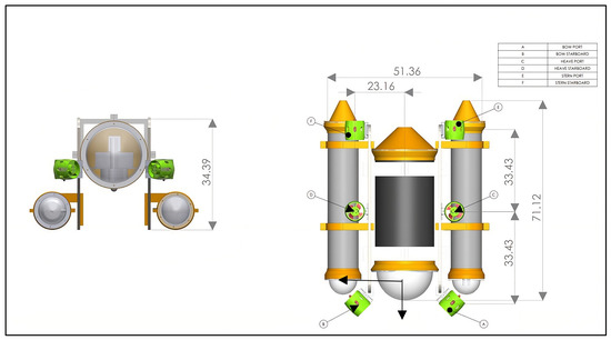
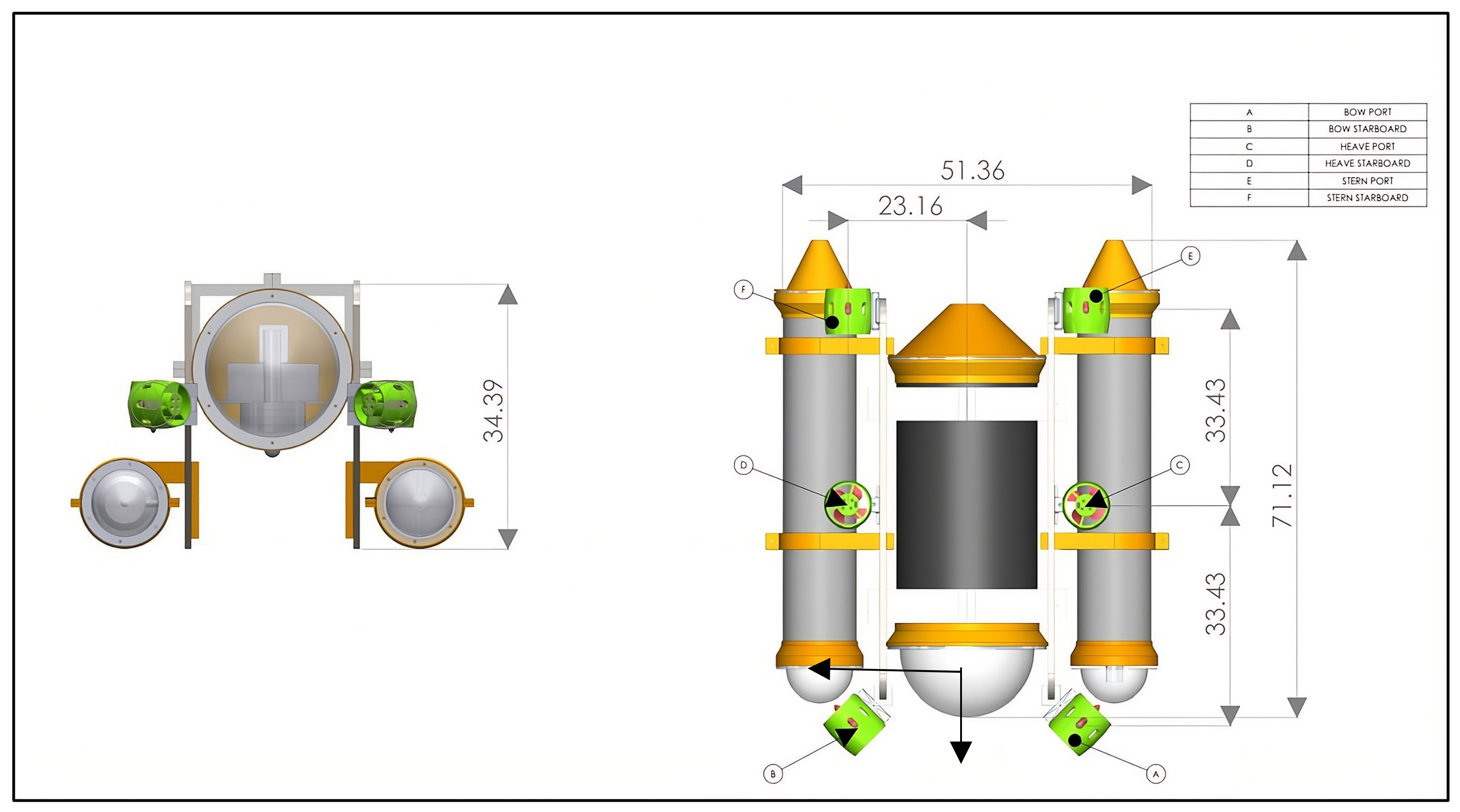
The Autonomous Underwater Vehicle (AUV) used in this research is a compact experimental platform specifically designed for maneuverability studies. The vehicle has a total length of 71.12 cm, with a beam width of 51.36 cm, and a depth measurement of 34.39 cm. These proportions place the AUV in the category of small-scale prototypes, making it suitable for controlled pool testing and laboratory-based hydrodynamic investigations. Despite its relatively modest size, the craft possesses a displacement of 33.64 kg, which provides sufficient stability during operation while still maintaining ease of handling in experimental environments. The dimensioned engineering drawing of the proposed three-hull AUV is presented in Figure 1.
Figure 1.
Dimensioned engineering drawing of the proposed trimaran Autonomous Underwater Vehicle (AUV).
In terms of performance, the vehicle is capable of achieving forward speeds of up to 4 knots, a velocity adequate for simulating realistic maneuvering scenarios such as turning, diving, and hovering motions within a confined pool space. The compact dimensions of the AUV make it suitable for controlled pool experiments and maneuvering studies under laboratory conditions.
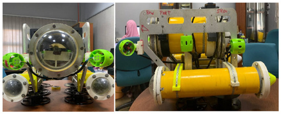
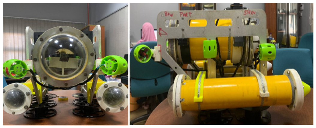
The weight distribution of the AUV is carefully arranged to support its maneuvering functions. The longitudinal center of gravity (LCG) is positioned 1.93 cm aft of amidships, a design choice that slightly shifts the mass toward the stern to enhance yaw responsiveness during turning maneuvers. These parameters were used as the main input for the maneuvering simulation and experimental validation. The complete physical parameters of the three-hull AUV used throughout this study are provided in Appendix A. The fabricated three-hull AUV used in the experimental validation is shown in Figure 2.
Figure 2.
Photograph of the fabricated trimaran AUV and thruster arrangement used for the experimental validation.
1.2. Hydrodynamic Coefficients of Three-Hull AUV
The hydrodynamic coefficients adopted in this study were obtained from CFD simulations performed on the same three-hull AUV geometry reported by Ayub et al. Prior to the AUV simulations, the CFD methodology was validated against the benchmark DARPA SUBOFF model to establish the accuracy of the numerical approach. Therefore, the hydrodynamic coefficients employed in the present study were not extrapolated from DARPA SUBOFF, but were directly computed for the three-hull AUV geometry. Although the results were not experimentally validated for the current AUV, they followed similar trends.
Table 1 presents the hydrodynamic coefficients calculated through CFD simulations for an AUV; the same methodology was previously applied to the standard DARPA model, yielding results that closely matched experimental data. This consistency suggests that the current results for the AUV are likely to be reliable [9].
Table 1.
Hydrodynamic coefficients adopted for the three-hull AUV maneuvering model [9].
The hydrodynamic coefficients listed in Table 1 were adopted from the CFD-based virtual PMM study reported by Ayub et al. [9]. These nondimensional coefficients constitute the hydrodynamic database used in the present study and are converted into dimensional form before being incorporated into the nonlinear maneuvering equations presented in Section 2.1.3 [13].
2. Methodology
2.1. Maneuvering Simulation
A MATLAB r2024based maneuvering simulation was developed to investigate the pivot turning behavior of an Autonomous Underwater Vehicle (AUV) under a specific thruster configuration. A reduced-order three-degrees-of-freedom formulation was employed to represent surge (), sway (), and yaw () motions. For computation, the maneuvering model adopts a diagonalized mass and damping representation, where cross-coupling hydrodynamic terms are neglected. This reduced-order formulation is intended for preliminary trajectory prediction and maneuvering trend analysis rather than high-fidelity dynamic reconstruction. Hydrodynamic coefficients and maneuvering behavior were referred from prior hydrodynamic investigations involving virtual PMM simulation [5], directional stability analysis [14], and PMM-based hydrodynamic coefficient estimation [3]. Similar 3DOF maneuvering behavior generated using a single actuator underwater robot has also been demonstrated through numerical simulation and experimental validation in previous studies [15].
The implemented configuration replicates the experimental setup, where a single front thruster is mounted at an inclination angle of 45°. This configuration primarily generates a yaw moment with coupled surge and sway components due to the oblique thrust direction.
The numerical analysis produces planar trajectory (x, y) and heading angle () response data as functions of time. Numerical integration was performed using a fixed time-step scheme with predefined simulation duration and time steps. The governing equations were integrated using a fixed-step forward Euler scheme with a constant time step of 0.0333 s, corresponding to the sampling interval of the experimental video tracking system. This time step was selected to maintain consistency between the numerical simulation and the experimental measurements.
2.1.1. Thruster Configuration
The total forces and yaw moment generated by the thrusters are computed through vector decomposition based on their orientations and positions relative to the center of gravity (COG).
The thruster orientation angles are defined as
The position vectors of each thruster relative to the COG are given by
In this maneuvering analysis, only Thruster 1 is activated with a constant thrust magnitude of N, while the remaining thrusters are inactive (). This configuration isolates the effect of a single obliquely oriented thruster on the vehicle dynamics.
2.1.2. Force and Moment Decomposition
The surge and sway forces are obtained by projecting the thrust vector onto the body-fixed axes:
The yaw moment about the z-axis is computed using the moment arm relative to the COG:
Since only is active, the total force and moment contributions are solely determined by its magnitude and orientation.
2.1.3. Hydrodynamic Model
The hydrodynamic forces and moments are modeled as nonlinear functions of the body-fixed velocities. Nonlinear hydrodynamic effects play an important role in underwater vehicle maneuvering, particularly during low-speed turning and high-yaw rate motions. Earlier maneuvering studies have demonstrated that higher-order nonlinear damping terms significantly improve the prediction accuracy of maneuvering simulations compared to purely linear formulations [16].
In the present study, the hydrodynamic coefficients were adopted directly from the CFD-based virtual PMM investigation reported by Ayub et al. [9]. No additional parameter identification or empirical optimization was performed using the experimental maneuvering data presented in this study. Instead, the experimentally measured pivot turn trajectory was used exclusively to evaluate the capability of the proposed reduced-order model under the investigated operating conditions.
Surge:
Sway:
Yaw:
The hydrodynamic derivatives used in Equations (4)–(6) represent the damping and coupling effects associated with the body-fixed motion components. The coefficient denotes the linear surge damping derivative, while represents the nonlinear quadratic surge drag coefficient. The coefficients and correspond to the sway force contributions generated by sway velocity and yaw rate, respectively. Similarly, and represent the yaw moment derivatives associated with sway velocity and yaw rate. Higher-order nonlinear effects are represented by and , which account for cubic nonlinear damping in sway and yaw motions.
In the initial condition (), all hydrodynamic forces and moments are zero. Since experimentally identified yaw damping derivatives were unavailable for the present vehicle, the CFD-derived nonlinear yaw damping coefficients reported by Ayub et al. were directly adopted in the maneuvering model without additional empirical tuning.
Earth-fixed position:
where and denote the Earth-fixed planar position coordinates and is the heading angle.
The body-fixed coordinate system follows the conventional marine craft notation, where the x-axis represents the longitudinal direction and the y-axis represents the lateral direction of the vehicle.
The body-fixed velocity vector is defined as
where , , and denote the body-fixed surge velocity, sway velocity, and yaw angular velocity, respectively.
2.1.4. Equations of Motion
The equations of motion are implemented using a simplified reduced-order 3DOF maneuvering formulation derived from classical marine craft dynamics [2] and underwater vehicle motion control theory [17]. The equations of motion in the body-fixed frame are expressed as
where M is the inertia matrix, τ is the thrust force and moment vector generated by the thrusters, and τhydro represents the nonlinear hydrodynamic force and moment components expressed as
where is the vehicle mass; is the yaw moment of inertia; is the longitudinal center of gravity position; and denote the added mass derivatives associated with surge, sway, and yaw motions.
2.2. Experimental Maneuvering
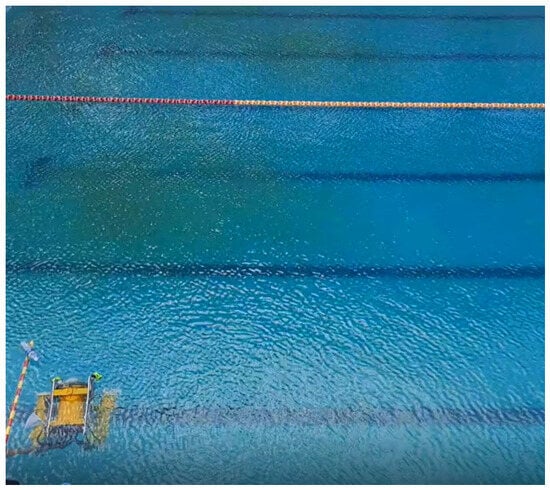
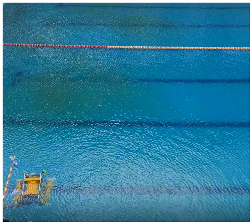
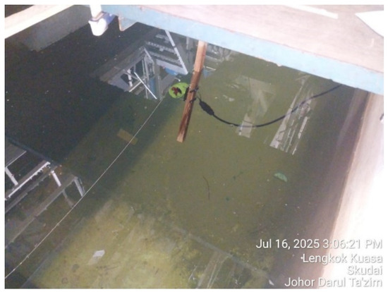
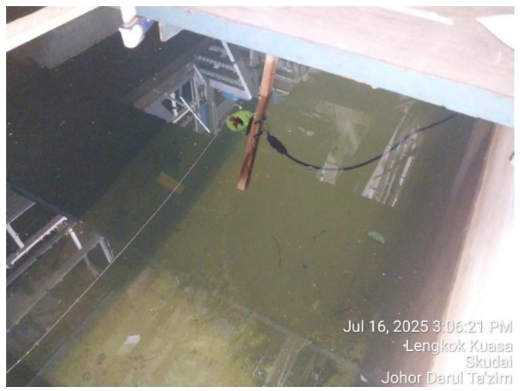
The experimental maneuvering pool test was carried out to observe and record the pivot turning behavior of the Autonomous Underwater Vehicle (AUV) in a controlled aquatic environment. Figure 3 illustrates the experimental pool setup used for the maneuvering validation. The AUV was placed in a test pool and commanded to perform a pivot maneuver using its front thruster positioned at a 45° angle to generate dominant yaw motion with limited forward translation.
Figure 3.
Experimental pool setup used for pivot turning maneuver validation of the three-hull AUV.
The experiments were conducted in the outdoor swimming pool, a 25 m freshwater facility. The available test area was significantly larger than the maneuvering trajectory of the three-hull AUV, thereby minimizing potential wall and boundary effects during the pivot turn experiments.
The trajectory of the AUV was captured using an overhead video camera, and the recorded footage was later processed using Tracker motion analysis software (Version 6.2.0. open source physics) to extract the planar position coordinates as a function of time [18].
An experimental procedure was conducted in a controlled water tank environment to investigate the motion behavior of the AUV when subjected to asymmetric thrust. The objective of this test was to assess the AUV’s response when only a single thruster, specifically the bow port (Thruster 1) unit, was activated. The selected thruster was set to a constant input level of 1500 PWM, while all other thrusters remained inactive. This configuration allowed the AUV to rotate and drift freely, providing an appropriate case for investigating asymmetric maneuvering behavior generated under actuated thrust conditions [15].
The experiment was carried out in a static pool with calm water conditions to minimize external disturbances such as current or waves. An overhead camera was mounted directly above the test area to record the motion of the AUV in the horizontal (X-Y) plane. The camera captured the entire maneuver sequence from the initial rest condition through the induced motion phase until the AUV slowed down due to hydrodynamic damping. After completing the physical test, the recorded video was processed using Tracker motion analysis software, enabling frame-by-frame extraction of the AUV’s position, generating time-series data for both the X and Y coordinates [18].
The propulsion system consists of six thrusters driven by Brushless DC Motors (BLDCs). Each thruster is controlled through an independent Electronic Speed Controller (ESC). A 12 V DC battery supplies power through a parallel distribution system, ensuring stable and uniform current delivery to each thruster. The overall electrical and control pathway can be described sequentially as the 12 V battery, the parallel power distribution, the ESCs, the BLDC thrusters, and finally the PWM signals generated by the Arduino (Arduino S.r., Monza, Italy) microcontroller. This configuration provides effective control of surge, yaw, and heave motions, while maintaining power efficiency and reducing the number of required control lines.
To evaluate maneuvering capability, a pivot turning maneuver to the right was executed with a total duration of 10 s. During this sequence, the bow port thruster was set to forward thrust at 1500 µs, while all the other thrusters remained off at 1000 µs.
Following the completion of the 10 s maneuver, all forward and reverse thrusters were switched off at 1000 µs, while the heave thrusters remained in their neutral state. To conclude the operation, the control loop was terminated, keeping the AUV in an idle condition. This structured procedure ensured consistency during experimental testing and allowed clear observation of the hydrodynamic response generated.
2.3. Thruster Modeling
The propulsion system of the AUV is modeled by establishing a relationship between the actuator input, expressed in Pulse Width Modulation (PWM), and the generated thrust force. In underwater propulsion systems, the thrust output is inherently nonlinear due to motor characteristics, propeller geometry, and fluid structure interaction effects [10]. Nonlinear thrust behavior is commonly observed in underwater propulsion systems due to wake interaction, propeller asymmetry, and motor dynamics, particularly near neutral operating conditions [19]. These findings are consistent with previously reported observations on compact underwater propulsion systems [12].
In this work, the thrust force is not approximated using a simple analytical equation but instead represented using an experimentally derived lookup table. The general relationship can be expressed as
where is the thrust force (N) and PWM represents the control input signal (typically in the range of 1000–2000 μs).
The thrust force generated by each thruster is assumed to act along its mounting direction. For a multi-thruster configuration, the total force and moment acting on the AUV in the body-fixed frame are obtained by resolving each thrust component into surge and sway directions:
where is the thrust generated by the -th thruster and is its mounting angle relative to the body-fixed x-axis.
The yaw moment generated by the thrusters is computed based on their positions relative to the center of gravity:
where represents the position of the -th thruster in the body-fixed coordinate system.
To account for the offset of the center of gravity, an additional correction term is included:
This approach allows the generated forces and moments to reflect the physical configuration of the AUV more accurately.
The resulting force vector applied to the dynamic model is expressed as
This thruster model is directly integrated into the maneuvering equations to simulate the AUV response under different control inputs.
2.4. Thrust Force Measurement Using Force Transducer
2.4.1. Force Transducer Calibration
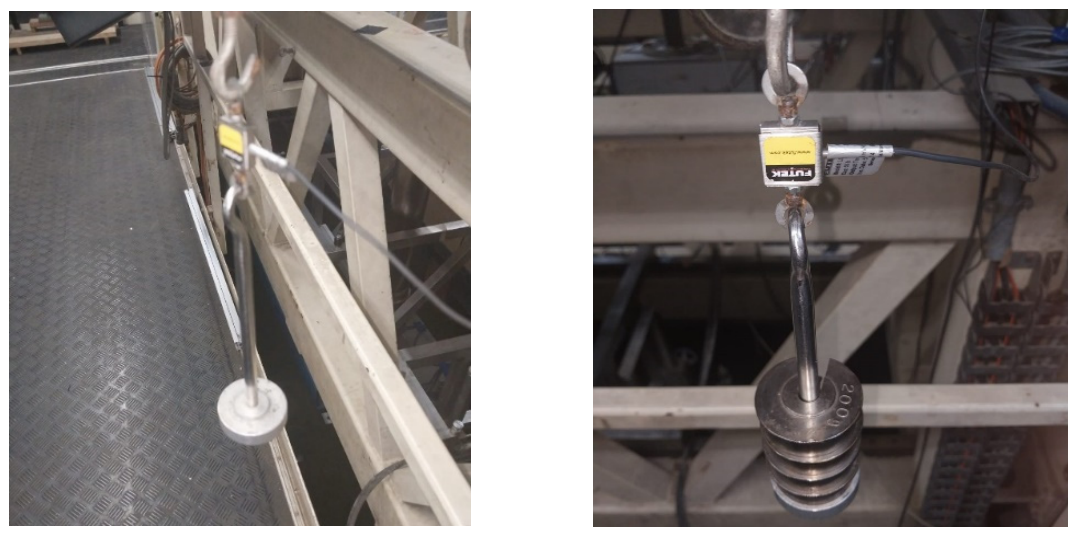
Before conducting thrust force measurements, it is essential to calibrate the force transducer to ensure the accuracy and reliability of the recorded data. A FUTEK LSB200 force transducer (FUTEC Advanced Sensor Technology, Irvine, CA, USA) was used due to its high precision and sensitivity for linear force measurement.
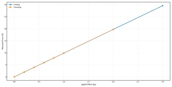
The calibration process was performed by applying known static loads and recording the corresponding sensor output during both loading (increasing force) and unloading (decreasing force) phases, as illustrated in Figure 4. This procedure is important to evaluate key characteristics of the measurement system, including linearity, repeatability, and hysteresis [20].
Figure 4.
Experimental setup used for calibration of the FUTEK LSB200 force transducer.
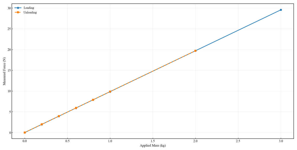
The calibration results are presented in Figure 5, which shows the relationship between the applied load and the measured force obtained from known masses ranging from 0 to 3 kg. The loads were applied incrementally, and the corresponding sensor outputs were recorded during both loading and unloading phases.
Figure 5.
Calibration characteristics of the FUTEK LSB200 force transducer under loading and unloading conditions.
The calibration curve exhibits a nearly linear relationship for both loading and unloading conditions, indicating good linearity and minimal hysteresis. This confirms that the force transducer provides reliable and consistent measurements for thrust characterization.
2.4.2. Thrust Measurement Procedure
Thrust force measurements were conducted to characterize the propulsion performance of the APISQUEEN U01 thruster (APISQUEEN, Shenzhen, China) used in the AUV prototype. The measured thrust characteristics reported in this study correspond only to the tested APISQUEEN U01 unit under the present experimental conditions and should not be interpreted as the manufacturer’s official performance specification. A FUTEK LSB200 force transducer was mounted on a static test rig, with the thruster aligned along the sensor’s sensitive axis, as illustrated in Figure 6. The thrust characterization was performed by varying the Pulse Width Modulation (PWM) input from 1000 to 2000 μs in increments of 100 μs using an Arduino-based controller [21]. At each PWM level, the generated thrust force was recorded after steady-state conditions were achieved, following standard underwater thruster characterization procedures adapted for the APISQUEEN U01 propulsion system [12]. Measurements were conducted in both forward and reverse directions to capture the bidirectional thrust characteristics, considering the asymmetric behavior commonly observed in underwater thrusters due to propeller geometry and motor efficiency [12].
Figure 6.
Experimental setup for underwater thruster force measurement using the FUTEK LSB200 force transducer.
3. Results
3.1. Experimental Trajectory and Heading Data
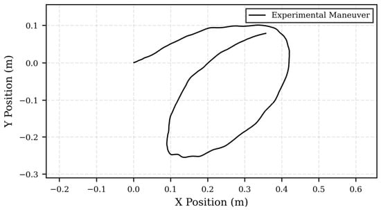
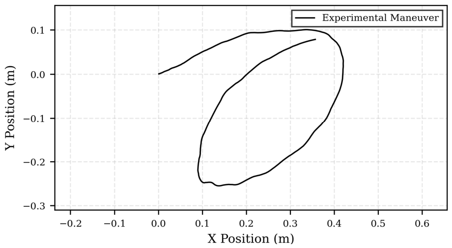
The experimental trajectory extracted from the video tracking analysis is presented in Figure 7. The measured trajectory exhibits the characteristic pivot turning behavior of the three-hull AUV under asymmetric thrust excitation. Following the activation of the inclined bow thruster, the vehicle undergoes a continuous clockwise rotational motion while simultaneously experiencing a limited translational displacement.
Figure 7.
Experimental trajectory obtained during the pivot turning maneuver of the three-hull AUV.
As shown in Figure 7, the trajectory forms a closed curved path with a relatively small turning radius, indicating that the applied thrust primarily generates a yaw moment rather than pure forward propulsion. Minor irregularities observed along the trajectory are attributed to measurement uncertainty associated with the video tracking process and small hydrodynamic disturbances during the experiment.
The extracted trajectory provides the experimental reference for validating the proposed maneuvering model. In addition to the planar trajectory, the corresponding heading response is analyzed in the subsequent section to assess the capability of the numerical model in reproducing the observed maneuvering behavior.
3.2. Thrust Force Measurement
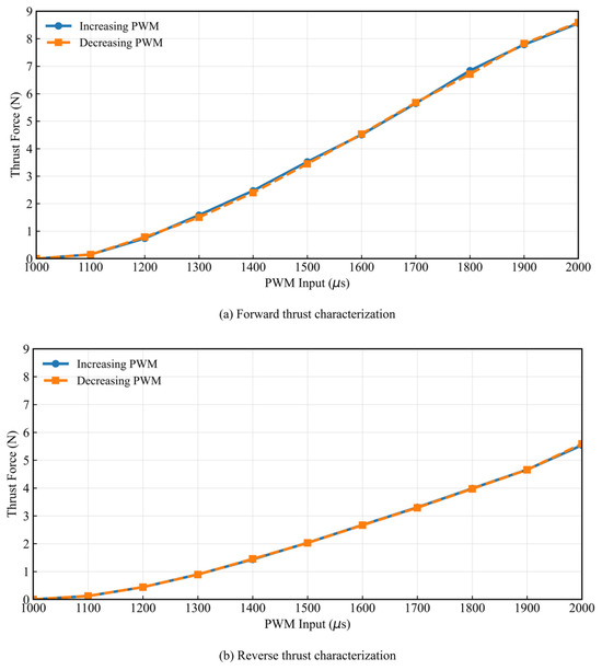
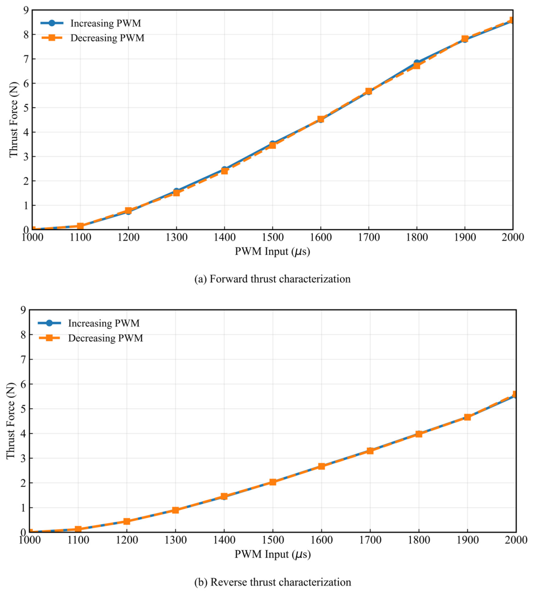
The relationship between PWM input and generated thrust force is presented in Figure 8 for both forward and reverse directions. A nonlinear relationship between PWM input and generated thrust force was observed, where the thrust force increases progressively with PWM input. The force transducer calibration and measurement procedure follow standard experimental measurement principles described in [19].
Figure 8.
Experimental thrust characterization under (a) forward and (b) reverse operating conditions.
In the forward direction, the thrust exhibits a relatively smooth and increasing trend, reaching its maximum value at higher PWM levels. In contrast, the reverse thrust is generally lower in magnitude, indicating an asymmetric response of the propulsion system. This behavior is consistent with previous studies and is primarily attributed to the propeller blade design and flow characteristics in reverse operation.
The nonlinear and asymmetric characteristics observed in the thrust measurements highlight the importance of using experimentally derived thrust data in maneuvering simulations. Simplified linear models would not be able to capture these effects accurately, leading to discrepancies in maneuvering predictions.
3.3. Numerical Maneuvering Results
A reduced-order planar dynamic model of the AUV was developed in MATLAB r2024 to simulate the pivot turning maneuver. The model captures the dominant surge, sway, and yaw dynamics using a simplified reduced-order planar maneuvering formulation. Hydrodynamic coefficients were adopted directly from the CFD-based virtual PMM study reported by Ayub et al., while experimentally measured thrust characteristics were incorporated without additional parameter optimization [9]. The present experimental comparison should be interpreted as an evaluation of the maneuvering framework rather than as an independent validation of the CFD-derived hydrodynamic coefficients themselves.
The propulsion input was modeled using experimentally obtained thrust characteristics, incorporating the nonlinear PWM thrust relationship. The 45° inclined thruster generates both yaw moment and a small surge component, resulting in combined rotational and translational motion.
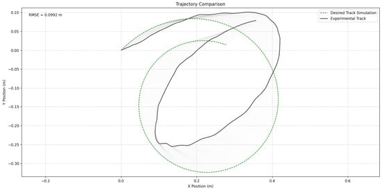
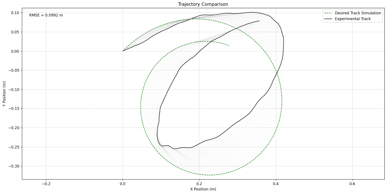
The predicted trajectory forms a circular maneuvering pattern consistent with pivot turning behavior, as shown in Figure 9. A good agreement can be observed between simulated and experimental trajectories, indicating that the model captures the essential maneuvering characteristics.
Figure 9.
Comparison between simulated and experimental pivot turning trajectories of the three-hull AUV. Gray lines connect the simulated and experimental positions at identical time steps.
Quantitative evaluation is performed using MAE, RMSE, Maximum Error, and NRMSE, as summarized in Table 2.
Table 2.
Error metrics between simulated and experimental AUV trajectories.
Average trajectory deviations remained relatively small, with RMSE and MAE values of 0.0992 m and 0.0905 m, respectively. These values indicate acceptable agreement relative to the trajectory scale. The Maximum Error of 0.1534 m occurs in localized regions, likely due to transient dynamics and measurement uncertainty. The NRMSE of 0.0698 (6.98%) confirms that the model achieves acceptable predictive capability.
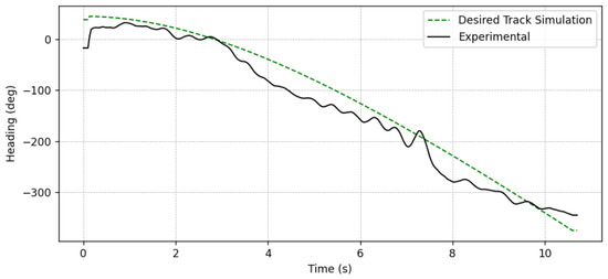
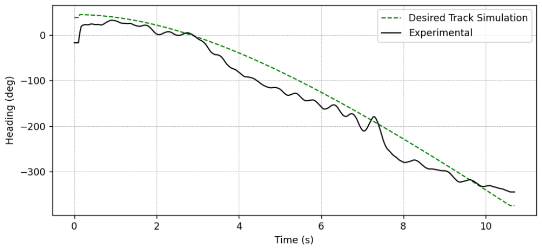
To further evaluate the rotational dynamics, the heading angle response is analyzed as shown in Figure 10.
Figure 10.
Comparison of simulated and experimental heading responses during the pivot turning maneuver.
Both simulated and experimental heading profiles exhibit a consistent decreasing trend, confirming that the model successfully captures the overall yaw motion of the AUV.
However, several discrepancies can be observed:
- The experimental heading decreases more rapidly after approximately 3 s, indicating that yaw dynamics appear to be slightly underpredicted.
- Small oscillations are present in the experimental data that are absent in the simulation. These fluctuations are attributed to measurement noise from the vision-based tracking system and unmodeled environmental disturbances.
- An initial offset between simulation and experiment can be observed, suggesting a mismatch in initial heading conditions.
Despite these differences, the overall trend agreement demonstrates that the model is capable of reproducing the dominant rotational behavior of the AUV.
Experimental observations support the validity of the simplified dynamic model in capturing key motion trends associated with coupled translational and rotational motion under single actuator operation [15]. Similar agreement between experimental and simulated maneuvering responses has also been reported in REMUS AUV validation studies [22]. A quantitative comparison between the experimental measurements and numerical predictions is presented in the following subsection.
4. Discussion
A quantitative comparison between simulated and experimental trajectories indicates a high level of agreement in reproducing the pivot turning maneuver. The RMSE of 0.0992 m and MAE of 0.0905 m confirm that the average deviation remains low throughout the maneuver, while the NRMSE of 6.98% demonstrates that the global prediction error is well bounded relative to the trajectory scale. The relatively small difference between RMSE and MAE further suggests a uniform error distribution, indicating stable model behavior without significant divergence. Similar levels of trajectory prediction accuracy have also been reported in previous AUV maneuvering validation studies. Prestero demonstrated that reduced-order underwater vehicle models are capable of reproducing maneuvering behavior with acceptable prediction errors when supported by experimentally identified hydrodynamic parameters [23].
These error levels fall within the typical range reported in marine maneuvering studies, where uncertainties in hydrodynamic coefficients, environmental disturbances, and actuator nonlinearities are unavoidable. Previous works in AUV and marine craft modeling have shown that prediction errors in the range of 5–10% are generally acceptable for reduced-order dynamic models, placing the present results within an expected and acceptable accuracy band [18].
The present validation should therefore be interpreted as an assessment of the capability of the adopted hydrodynamic model to reproduce a representative low-speed pivot turn maneuver, rather than as a comprehensive validation of the model under all maneuvering conditions. The hydrodynamic coefficients employed in this study were adopted directly from the CFD-based virtual PMM investigation reported by Ayub et al. [9] and were evaluated using the representative experimental maneuver without additional parameter optimization. Consequently, the reported agreement demonstrates the applicability of the proposed reduced-order model for the investigated operating conditions, while validation under additional operating scenarios, including different thrust levels, opposite-direction pivot turns, turning circle tests, and zigzag maneuvers, remains an important subject for future investigation.
Although the present study demonstrates that the proposed reduced-order maneuvering model is capable of reproducing the experimentally observed pivot turn trajectory under the investigated operating conditions, the reported results should not be interpreted as evidence of general predictive capability across different maneuvering scenarios or vehicle configurations. The validation is intentionally limited to a single representative low-speed pivot turn maneuver performed under controlled laboratory conditions. Consequently, the present study should be regarded as an initial proof of concept demonstrating the feasibility of integrating independently derived CFD-based hydrodynamic coefficients with experimentally characterized thruster forces for trajectory-level maneuver prediction.
Future studies should extend the validation to repeated experiments under identical operating conditions in order to quantify repeatability, experimental uncertainty, and confidence bounds. Additional validation using independent maneuvering cases, including opposite-direction pivot turns, different thrust levels, turning circle maneuvers, and zigzag tests, will also be necessary to evaluate the general applicability and predictive capability of the proposed maneuvering framework.
While trajectory agreement is strong, additional insight can be obtained from the heading response analysis. The comparison of heading angle evolution reveals that the experimental heading decreases more rapidly than the simulated result, particularly after the initial phase of motion. This indicates that the model slightly underestimates the yaw dynamics of the vehicle. Furthermore, small fluctuations observed in the experimental heading, which are absent in the simulation, highlight the presence of measurement noise and unmodeled disturbances.
The observed discrepancies can be primarily attributed to limitations in hydrodynamic modeling. In particular, cross-coupling derivatives such as and play a critical role in determining the interaction between sway and yaw motions, which becomes especially significant in pivot turning configurations. The use of a single front thruster inclined at 45° introduces a strongly coupled force moment system, generating both lateral force and yaw moment simultaneously. Under this configuration, the maneuver becomes highly sensitive to hydrodynamic parameters, including , , , and . The importance of coupled hydrodynamic interactions in underwater vehicle maneuvering has also been highlighted in previous experimental identification studies. Open-frame and multi-body underwater vehicles are particularly sensitive to cross-coupling hydrodynamic derivatives due to flow interference effects between structural components and propulsion systems [24].
An underestimation of Yr would reduce the predicted lateral force induced by yaw rate, resulting in a larger turning radius, while inaccuracies in Nv directly affect yaw moment generation due to sway velocity, thereby influencing the angular velocity and heading evolution. The slight radial deviation observed in the trajectory suggests that the simplified reduced-order formulation does not fully capture all surge, sway, and yaw coupling effects. This limitation is likely associated with the simplified modeling assumptions, including the use of CFD-derived hydrodynamic coefficients without further experimental identification and the omission of several higher-order nonlinear interactions, rather than deficiencies in the adopted hydrodynamic dataset itself.
Higher-order nonlinear effects such as viscous cross-flow drag, flow separation, and thruster–hull interaction are not explicitly included in the model. These effects become increasingly important in low-speed, high-rotation maneuvers such as pivot turning and may contribute to localized deviations, particularly during transient phases.
Despite these limitations, the proposed formulation reproduces the dominant physical characteristics of the maneuver, including sustained yaw rotation, bounded trajectory, and consistent heading evolution. Incorporating experimentally measured thrust characteristics improves the physical realism of the maneuvering prediction, enabling the simulation to capture nonlinear propulsion behavior that would otherwise be neglected.
From a modeling perspective, these findings support the assumption that a reduced-order planar dynamic model is sufficient to capture the essential dynamics of pivot turning for small-scale AUVs. Comparable reduced-order dynamic approaches have also been successfully applied to REMUS-class AUV simulations [19]. The ability to reproduce both trajectory and heading behavior with errors below 10% indicates that the dominant maneuvering physics are governed primarily by surge yaw coupling, even under a nonconventional single-thruster configuration.
From an engineering standpoint, these findings demonstrate that simplified actuation systems, such as a single inclined thruster, can be effectively modeled using classical maneuvering formulations when supported by appropriate hydrodynamic coefficients and experimentally derived thrust characteristics. This has important implications for the design of compact and energy-efficient AUV systems. Recent studies on underwater vehicle propulsion systems have shown that thruster arrangement and orientation significantly influence maneuvering efficiency, yaw authority, and energy consumption. Optimized thruster configurations can improve maneuverability while maintaining compact vehicle architecture and reducing control complexity [25].
One limitation of the present study is that the experimental validation was performed using a single representative pivot turn maneuver under controlled laboratory conditions. Consequently, the reported RMSE and MAE values should be interpreted as performance indicators for this representative maneuver rather than statistical measures of maneuvering repeatability. Although the obtained agreement demonstrates the capability of the proposed reduced-order model to reproduce the dominant trajectory and heading trends, repeated experimental trials under identical operating conditions are required to quantify experimental variability and establish confidence bounds. Such statistical validation will be considered in future work.
This present study provides a reproducible workflow for integrating independently derived CFD-based hydrodynamic coefficients with experimentally characterized thruster forces into a computationally efficient maneuvering model. This workflow can serve as an initial validation methodology for researchers developing reduced-order maneuvering models of compact multi-hull AUVs before undertaking more extensive system identification or experimental campaigns.
Future work should focus on improving the accuracy of hydrodynamic coefficients through system identification or CFD-based estimation, particularly for cross-coupling terms such as and . Incorporating higher-fidelity nonlinear effects and real-time sensor-based measurements is expected to further enhance predictive accuracy, especially in transient maneuvering conditions.
5. Conclusions
The pivot turning characteristics of the proposed three-hull AUV were investigated through a combined numerical and experimental approach. Experimental maneuvering tests conducted in a controlled pool environment demonstrated that the developed 3DOF maneuvering formulation successfully reproduced the dominant trajectory and heading behavior observed during the pivot turning maneuver.
Quantitative trajectory evaluation showed relatively small prediction errors, with RMSE and MAE values of 0.0992 m and 0.0905 m, respectively, indicating acceptable predictive capability for preliminary maneuvering analysis. Although several deviations were observed in the heading response, particularly during the later stages of the maneuver, the overall motion trend remained consistent with experimental observations. These discrepancies are primarily attributed to simplified hydrodynamic assumptions, unmodeled nonlinear effects, and environmental disturbances during testing.
The incorporation of experimentally measured thrust characteristics improved the physical realism of the propulsion model and contributed to more representative maneuvering predictions under asymmetric thrust conditions. The results further demonstrate that reduced-order planar maneuvering models can provide sufficiently accurate representations of pivot turning behavior for compact multi-hull AUV configurations when supported by appropriate hydrodynamic coefficients and thrust characterization data.
The present validation is limited to a representative experimental maneuver. Future studies will incorporate repeated experiments and statistical uncertainty analysis to further assess the robustness and repeatability of the proposed maneuvering model.
Several limitations remain in the present study. The hydrodynamic coefficients were adopted from prior CFD investigations and were not experimentally identified for the current vehicle configuration. The maneuvering model employs simplified diagonalized mass and damping matrices without fully coupled nonlinear hydrodynamic interactions. Environmental disturbances such as free surface effects and turbulence were also neglected during simulation. Future work should include experimentally identified coefficients, higher-fidelity hydrodynamic coupling, and closed-loop maneuvering control implementation.
The proposed approach provides a practical foundation for future development of maneuvering control systems, including PID and model-based controllers, as well as further investigations involving turning circle, zigzag, and fully coupled maneuvering simulations under more complex underwater operating conditions.
The findings of this study are limited to the experimental conditions investigated and should not be generalized to other maneuvering scenarios or operating conditions without additional validation. Although the present results provide initial evidence supporting the proposed modeling framework, broader experimental verification involving repeated trials, statistical uncertainty analysis, multiple thrust levels, opposite-direction pivot turns, turning circle maneuvers, and zigzag tests will be required before the model can be considered a generally applicable maneuvering prediction tool for trimaran AUVs.
Author Contributions
Conceptualization, P.T., L.F.B. and A.M.; methodology, L.F.B., A.M. and P.T.; software, L.F.B., P.T. and N.R.H.; validation, L.F.B., N.R.H. and A.M.; formal analysis, L.F.B. and P.T.; investigation, L.F.B. and P.T.; resources, P.T. and E.D.A.; data curation, L.F.B.; writing—original draft preparation, L.F.B., P.T., N.R.H. and E.D.A.; writing—review and editing, P.T., E.D.A., A.M., L.F.B. and N.R.H.; visualization, L.F.B.; supervision, A.M.; project administration, L.F.B.; funding acquisition, L.F.B. All authors have read and agreed to the published version of the manuscript.
Funding
This research was funded by the Ministry of Finance, through the Indonesia Endowment Fund for Education or Lembaga Pengelola Dana Pendidikan (LPDP).
Data Availability Statement
The original contributions presented in this study are included in the paper. Further inquiries can be directed to the corresponding author.
Acknowledgments
The authors would like to take this opportunity to thank the Marine Technology Center, Universiti Teknologi Malaysia, and to give special thanks to Adi Maimun for the information and data support in this research.
Conflicts of Interest
The authors declare no conflicts of interest.
Abbreviations
The following abbreviations are used in this manuscript:
| AUV | Autonomous Underwater Vehicle |
| BLDC | Brushless DC Motor |
| CFD | Computational Fluid Dynamics |
| COG | Center of Gravity |
| DOF | Degree of Freedom |
| ESC | Electronic Speed Controller |
| MAE | Mean Absolute Error |
| NRMSE | Normalized Root Mean Square Error |
| PMM | Planar Motion Mechanism |
| PWM | Pulse Width Modulation |
| RMSE | Root Mean Square Error |
Appendix A
Table A1.
Vehicle physical parameters of the three-hull AUV.
References
- Yoerger, D.R.; Jakuba, M.; Bradley, A.M.; Bingham, B. Techniques for Deep Sea Near Bottom Survey Using an Autonomous Underwater Vehicle. Int. J. Robot. Res. 2007, 26, 41–54. [Google Scholar] [CrossRef] [Scilit]
- Fossen, T.I. Handbook of Marine Craft Hydrodynamics and Motion Control; Wiley: Chichester, UK, 2011. [Google Scholar]
- Lin, Y.-H.; Chiu, Y.-C. The estimation of hydrodynamic coefficients of an autonomous underwater vehicle by comparing a dynamic mesh model with a horizontal planar motion mechanism experiment. Ocean Eng. 2022, 249, 110847. [Google Scholar] [CrossRef] [Scilit]
- Hong, L.; Fang, R.; Cai, X.; Wang, X. Numerical Investigation on Hydrodynamic Performance of a Portable AUV. J. Mar. Sci. Eng. 2021, 9, 812. [Google Scholar] [CrossRef] [Scilit]
- Ardeshiri, S.; Mousavizadegan, S.H.; Kheradmand, S. Virtual simulation of PMM tests independent of test parameters. Brodgradnja 2020, 71, 55–73. [Google Scholar] [CrossRef] [Scilit]
- Shariati, S.K.; Mousavizadegan, S.H. The effect of appendages on the hydrodynamic characteristics of an underwater vehicle near the free surface. Appl. Ocean Res. 2017, 67, 31–43. [Google Scholar] [CrossRef] [Scilit]
- Xiang, X.; Yu, C.; Zhang, Q.; Wilson, P.A.; Xu, G. Manoeuvring-based actuation evaluation of an AUV with control surfaces and through-body thrusters. Appl. Ocean Res. 2020, 101, 102213. [Google Scholar] [CrossRef] [Scilit]
- Yasukawa, H.; Yoshimura, Y. Introduction of MMG Standard Method for Ship Maneuvering Predictions. J. Mar. Sci. Technol. 2015, 20, 37–52. [Google Scholar] [CrossRef] [Scilit]
- Ayub, A. Numerical Estimation of Hydrodynamic Coefficients and Directional Stability of an AUV. M. Eng. Thesis, Universiti Teknologi Malaysia, Johor Bahru, Malaysia, 2024. [Google Scholar]
- Ahmad, M.S.; Hasnan, M.A.A.; Shaharuddin, N.M.R.; Ayub, A. Effect of Appendages on Resistance and Lift of an Underwater Vehicle. In Proceedings of the International Conference on Marine Technology (MARTEC 2024), Johor Bahru, Malaysia, 24–26 September 2024. [Google Scholar]
- Vu, H.-P.; Le, T.-L.; Ngo, N.-A.; Truong, N.T.; Tran, T.-H.; Tran, Q.-L. A CFD Study of Hydrodynamic Characteristics of a Twin Hybrid Autonomous Underwater Vehicle. Results Eng. 2025, 26, 104792. [Google Scholar] [CrossRef] [Scilit]
- APISQUEEN. U01 12V–16V 2Kg Thrust Brushless Underwater Thruster Specifications. Available online: https://www.underwaterthruster.com/products/u01-12v-16v-200w-2kg-thrust-brushless-underwater-subsea-thruster-propeller-propulsion-with-bi-directional-control-esc-for-rov-boat (accessed on 19 May 2026).
- Quang, L.; Tuan, P.A.; Huong, P.T.T. Hydrodynamic and Dynamic Analysis to Determine the Longitudinal Hydrodynamic Coefficients of an Autonomous Underwater Vehicle. J. Sci. Technol. 2020, 146, 043–048. [Google Scholar]
- Saout, O.; Ananthakrishnan, P. Hydrodynamic and dynamic analysis to determine the directional stability of an underwater vehicle near a free surface. Appl. Ocean Res. 2011, 33, 158–167. [Google Scholar] [CrossRef] [Scilit]
- Kunimatsu, K.; Hattori, Y.; Kurabayashi, D. Single-actuator AUV performing 3-DOF motion. Adv. Robot. 2020, 34, 282–298. [Google Scholar] [CrossRef] [Scilit]
- Xu, F.; Zou, Z.-J.; Yin, J.-C.; Cao, J. Identification modeling of underwater vehicles’ nonlinear dynamics based on support vector machines. Ocean Eng. 2013, 67, 68–76. [Google Scholar] [CrossRef] [Scilit]
- Fossen, T.I. Guidance and Control of Ocean Vehicles; Wiley: Chichester, UK, 1994. [Google Scholar]
- Brown, D.; Cox, A.J. Innovative uses of video analysis. Phys. Teach. 2009, 47, 145–150. [Google Scholar] [CrossRef] [Scilit]
- Kim, J.; Chung, W.K. Accurate and practical thruster modeling for underwater vehicles. Ocean Eng. 2006, 33, 566–586. [Google Scholar] [CrossRef] [Scilit]
- Doebelin, E.O. Measurement Systems: Application and Design; McGraw-Hill: New York, NY, USA, 2004. [Google Scholar]
- Banzi, M. Getting Started with Arduino; O’Reilly Media, Inc.: Sebastopol, CA, USA, 2009. [Google Scholar]
- Prestero, T. Verification of a Six-Degree of Freedom Simulation Model for the REMUS AUV. Master’s Thesis, Massachusetts Institute of Technology, Cambridge, MA, USA, 2001. [Google Scholar]
- Evans, J.; Nahon, M. Dynamics modeling and performance evaluation of an autonomous underwater vehicle. Ocean Eng. 2004, 31, 1835–1858. [Google Scholar] [CrossRef] [Scilit]
- Avila, J.P.; Donha, D.C.; Adamowski, J.C. Experimental model identification of open-frame underwater vehicles. Ocean Eng. 2013, 60, 81–94. [Google Scholar] [CrossRef] [Scilit]
- Krishnan, A.K.S.; Kadiyam, J.; Mohan, S. Comparative performance investigations of the intervention-class underwater vehicle with different possible thruster configurations using eight identical thrusters. Ocean Eng. 2023, 288, 116147. [Google Scholar] [CrossRef] [Scilit]

Disclaimer/Publisher’s Note: The statements, opinions and data contained in all publications are solely those of the individual author(s) and contributor(s) and not of MDPI and/or the editor(s). MDPI and/or the editor(s) disclaim responsibility for any injury to people or property resulting from any ideas, methods, instructions or products referred to in the content. |
© 2026 by the authors. Licensee MDPI, Basel, Switzerland. This article is an open access article distributed under the terms and conditions of the Creative Commons Attribution (CC BY) license.