


Highlights
What are the main findings?
- Experimental evaluation of a drone-enabled hybrid UOC-RF communication for real-time underwater video streaming from offshore to onshore.
What are the implications of the main findings?
- The evaluation of RSSI, SINR, and throughput was conducted over 5G networks at 700 MHz and 2600 MHz, with ROV video streaming at 10 to 60 frames per second (fps).
- Results confirm feasibility and provide practical design insights for integrating underwater drone-enabled hybrid communication into marine observation.
Abstract
This paper proposes a hybrid underwater drone communication system that combines underwater optical communication (UOC) and radio-frequency (RF) communication to support real-time video streaming in underwater environments. The system consists of a remotely operated vehicle (ROV) that transmits video to a surface gateway, which relays the video to onshore facilities through a 5G network. An outdoor experiment conducted in a maritime environment measured the received signal strength indicator (RSSI), signal-to-interference-plus-noise ratio (SINR), occupied bandwidth, and end-to-end (E2E) throughput at 700 MHz and 2600 MHz with video frame rates ranging from 10 to 60 fps. The results show that the 700 MHz frequency band provides higher RSSI and SINR, which support more reliable long-range communications, while the 2600 MHz frequency band provides lower RSSI and SINR but a larger bandwidth. The maximum E2E throughput achieved was 53.5 Mbps at 700 MHz and 58.64 Mbps at 2600 MHz. Increasing frame rates mainly affects throughput by reducing SINR. These results analyze the coverage–capacity trade-off and provide valuable insights for drone-assisted hybrid UOC-RF communication in underwater video streaming applications.
1. Introduction
Underwater drones, commonly categorized as ROVs and autonomous underwater vehicles (AUVs) [1], have become essential tools for marine exploration, environmental monitoring, offshore inspection, and underwater imaging. Compared with human divers, underwater drones can operate in hazardous environments, reach greater depths, and provide continuous data collection without the associated safety risks. Among the collected data types, real-time video streaming plays a critical role in situational awareness, remote operation, and immersive virtual reality (VR) applications, particularly for marine observation [2].
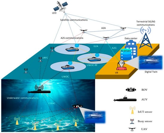
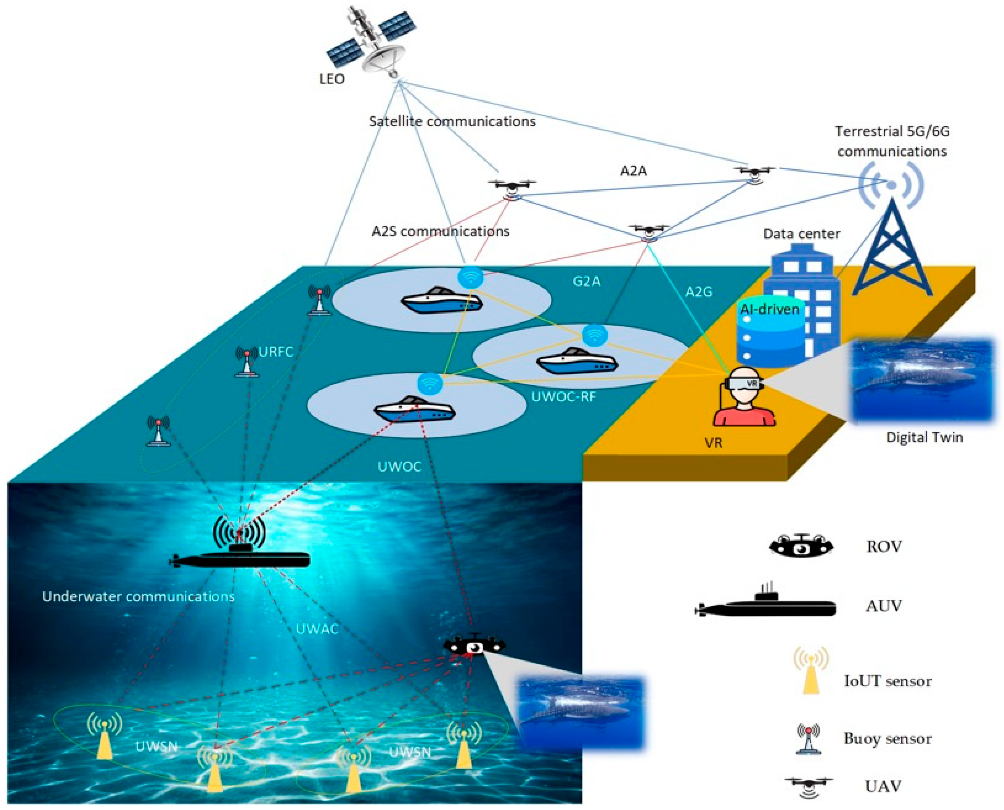
Figure 1 shows an integrated sensing and communication (ISAC) system for marine observation that integrates underwater, surface, aerial, terrestrial, and satellite networks to enable real-time data transfer and immersive applications for underwater drone systems. In the underwater environment, AUVs, ROVs, and Internet of Underwater Things (IoUT) sensor nodes form an underwater wireless sensor network (UWSN). Data are transmitted via underwater acoustic communication (UWAC) and underwater wireless optical communication (UWOC), enabling high-fidelity sensing and video capture over short- to medium-range distances, even in challenging aquatic conditions [2,3].
Figure 1.
Integrated sensing and communications for marine observation [2].
Surface-level platforms, such as smart buoys and vessels, serve as gateways that link underwater communication systems to terrestrial networks. Hybrid UWOC and RF links support surface-based data collection, reducing RF signal loss underwater. Unmanned aerial vehicles (UAVs) enable aerial relaying via air-to-air (A2A), air-to-ground (A2G), and ground-to-air (G2A) links, expanding coverage and improving connectivity reliability in coastal and offshore areas [4,5,6].
At the terrestrial and space layers, surface and aerial gateways connect to terrestrial 5G/6G infrastructure and low-earth-orbit (LEO) satellite systems, enabling long-range, high-throughput data transmission to data centers and cloud-based platforms. These infrastructures support artificial intelligence (AI)-driven data processing, digital twin construction, and immersive VR visualization, enabling users to interact with real-time underwater scenes and sensor data [7,8].
Despite these advantages, reliable wireless communication between underwater drones and remote users remains a fundamental challenge [9]. Traditional underwater communication techniques, including acoustic and RF methods [10,11], are constrained by low data rates, high latency, short communication ranges, and sensitivity to environmental conditions. In contrast, RF communication offers seamless integration with terrestrial wireless networks [12], particularly 5G cellular systems, which provide ultra-high data rates, low latency, and wide coverage [13].
Recent advances in 5G networks have enabled new possibilities for extending underwater drone communication beyond line-of-sight (LOS) limitations through surface gateways connected to 5G infrastructure [14,15]. By relaying underwater data to onshore cloud or edge servers, real-time video streaming and remote operation can be achieved. However, the performance of such systems is highly dependent on key physical-layer parameters, including RSSI, transmission rate, frequency band selection, and available bandwidth.
Although several studies have explored underwater communication technologies [16,17,18], quantitative experimental evaluations of RSSI and throughput for underwater drone systems integrated with commercial 5G networks remain limited. In particular, the trade-offs among coverage, signal stability, and achievable data rates across different 5G frequency bands remain insufficiently investigated.
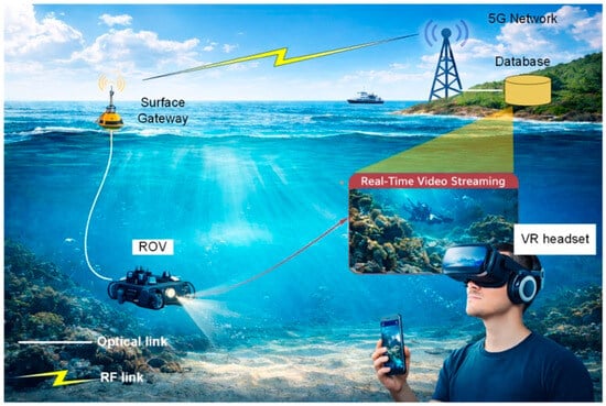
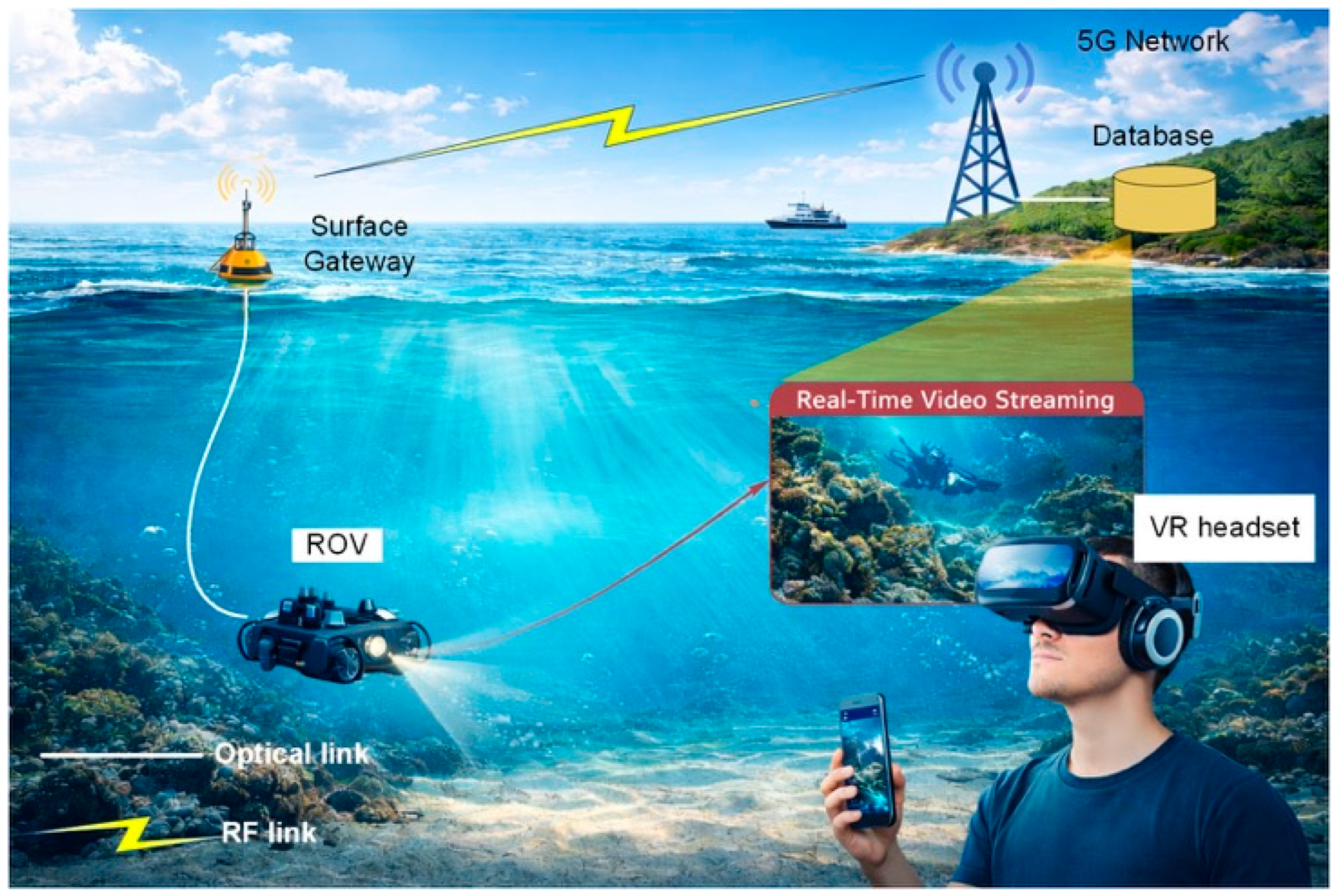
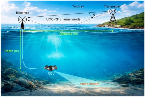
To address the research gap, this paper experimentally examined the RSSI and throughput of a drone-enabled hybrid communication system over a 5G network for real-time underwater video streaming. The hybrid underwater communication system evaluates UOC-RF at the physical layer, focusing on RSSI behavior, SINR, and real-time video streaming throughput. The ROV captures live video and transmits it to a surface gateway via an optical link. The analytical model is shown in Figure 2. From there, the surface buoy, serving as a gateway, forwards the ROV’s video to a VR headset at a terrestrial station via a 5G network. This communication framework relies on UOC-RF.
Figure 2.
Video streaming through a hybrid communication system used in marine observation, which integrates an underwater drone with a VR headset.
The main contributions of this paper are summarized as follows.
- Design a practical underwater drone communication model that integrates an ROV, a surface gateway, and the terrestrial 5G network.
- A two-state communication model is used for the underwater drone, first employing the UOC communication state and then the RF communication state, as part of the hybrid communication approach.
- Evaluate the RSSI, SINR, and E2E throughput across 5G frequencies at 700 MHz and 2600 MHz by varying the video frame rate from 10 to 60 fps for ROV video streaming.
2. Related Works
Wireless communications for underwater drones have been widely used via acoustic, optical, and hybrid methods [19,20,21]. Onasami et al. [22] introduced an acoustic communication system designed for long-distance underwater transmission that experiences low water attenuation. However, this approach is constrained by limited bandwidth, elevated latency, and susceptibility to multipath and Doppler effects, which hinder its ability to support high-definition real-time video streaming.
Kaushal et al. [23] discussed the UWOC link used by underwater drones. This communication method has gained interest due to its high data transfer rates, allowing gigabit-level real-time video streaming over short distances in AUV operations. However, UWOC is highly sensitive to water turbidity, misalignment, and scattering, limiting its practical use in dynamic marine environments.
Li et al. [24] introduced a hybrid communication system that combines RF and UWOC at the surface to address the limitations of UWAC and UWOC. They show that underwater drones send data to a surface buoy, which then forwards it to onshore infrastructure via RF. This approach enables seamless integration with terrestrial networks and helps overcome underwater propagation issues.
With the rollout of 5G networks, numerous studies have examined their impact on maritime and aerial communications [25,26,27]. 5G delivers enhanced mobile broadband (eMBB), ultra-reliable low-latency communication (URLLC), and massive machine-type communication (mMTC), which are suitable for real-time video streaming and remote operations [28]. Experimental results [29,30] indicate that lower-frequency bands, such as sub-1 GHz, offer wider coverage, whereas mid-band frequencies provide higher data rates but have shorter ranges.
Most existing research mainly concentrates on maritime surface communication, UAVs, and simulation-based testing. There is a lack of experimental studies on RSSI, SINR, and throughput for underwater drone systems connected to 5G networks. Additionally, few studies offer detailed comparisons of different 5G frequency bands in maritime channel modeling scenarios [31,32,33].
As shown in Table 1, prior work has typically focused on single communication or partial 5G integration. In contrast, this work presents both a 5G network and real-time underwater video streaming of a drone-enabled hybrid UOC-RF communication system.
Table 1.
Comparison between related works and this study.
Recent studies [34,35] have further advanced underwater optical wireless communication by developing detailed channel models for IoUT environments and by investigating intelligent receiver designs to mitigate absorption, scattering, and turbulence. These works emphasize the importance of accurate physical-layer modeling and adaptive signal processing for reliable high-speed underwater links. In contrast, this study experimentally evaluated a hybrid optical-5G communication framework in a real maritime scenario, extending prior optical modeling research toward the practical integration of drone-enabled systems.
3. System Model
The system model describes a two-hop uplink architecture for a real-time underwater video stream: the underwater state is from the ROV to the surface gateway via UOC, while the surface state uses an RF link over a 5G network
3.1. UOC-RF Communication System
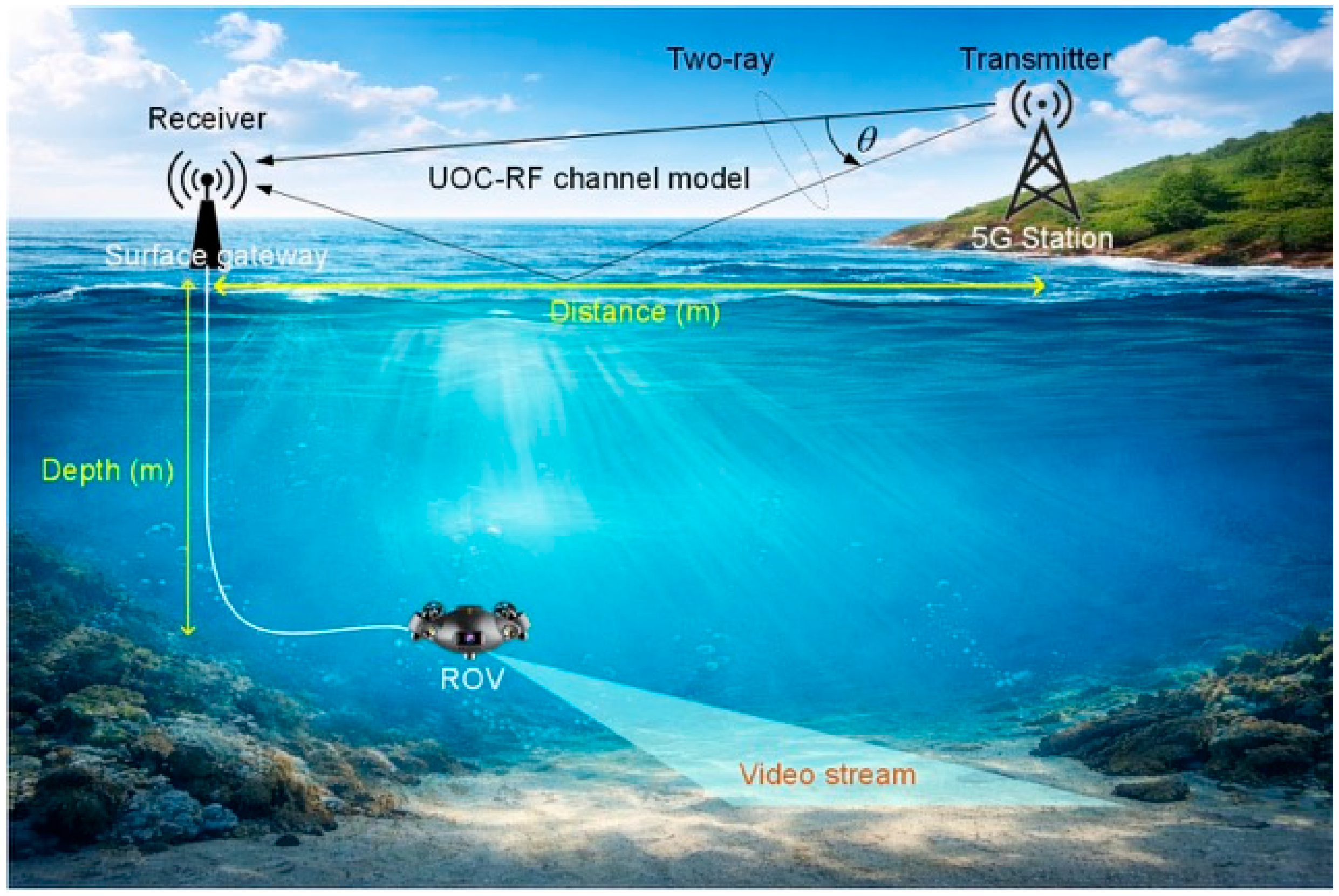
Considering the UOC-RF communication system shown in Figure 3, where the transmitter is a 5G station and the receiver is a surface gateway. Figure 3 depicts a hybrid UOC-RF architecture for real-time video streaming from an underwater ROV to the 5G network. Note that the ROV at depth transmits the video via an underwater optical link to a surface gateway. The surface gateway relays data to the 5G station over an above-water RF channel. Because propagation occurs over the sea surface, the RF link is modeled as a two-ray model [36]. The elevation angle represents the geometry between the transmitter and receiver, affecting the path difference and interference pattern.
Figure 3.
Schematic of the UOC-RF communication system.
At the UOC state rate, determine as the transmission rate between the ROV and surface gateway, and as the throughput between the surface gateway and 5G onshore station. The end-to-end (E2E) achievable uplink UOC is
where is the efficiency of real-time video streaming.
For stable real-time video streaming, the feasibility condition is
where is the required data rate; denotes the compressed video frame rate generated by the ROV camera, determined by video resolution, frame rate, and encoding scheme; accounts for the control, telemetry, and signaling data; is a rate margin introduced to compensate for time-varying channel conditions, scheduling delays, packet retransmissions, and short-term throughput fluctuations caused by fading, interference, and two-ray effects over the sea surface.
3.1.1. Underwater Optical Communication Link
The received power of UOC can be analyzed using the Beer–Lambert (BL) model [37], which is expressed as
where represents the optical transmit power of the ROV-mounted light source, while and denote the optical efficiencies of the transmitter and receiver, respectively, accounting for losses due to optical components, coupling inefficiencies, and detector responsivity. The term of is the geometric spreading loss and beam divergence, which arise from the optical beam’s finite divergence angle and potential misalignment between the transmitter and receiver. The is the attenuation coefficient of the water medium.
The output of the signal-to-interference plus noise (SINR) ratio for the UOC link is expressed as
where denotes the noise power and represents the interference power at the surface gateway.
Finally, the throughput of the UOC link is given by
where represents the optical bandwidth channel and captures the implementation loss.
3.1.2. Radio Frequency Link
Considering the transmitter and receiver sides of the RF link, the geometry of the two-ray model can be expressed as:
The line-of sight (LOS) path length is
where represents the distance between the transmitter and receiver sides, and denote the transmitter height and receiver height, respectively.
The reflection-path or non-LOS length is
The path difference is , while the elevation angle approximation is
3.1.3. Two-Ray Model
In the complex baseband, the received field is the sum of direct and reflected components as
where and denote the propagation constants and the sea-surface reflection coefficient that depends on polarization, incidence angle, and sea state [34].
Thus, the received power at the receiver is
Additionally, the Two-Ray path loss model is expressed as
Then, the total of received power is substituted as
where represents miscellaneous system losses.
Considering the RSSI as the total received power at the surface gateway is given by
where represents the aggregate interference power received at the receiver, while denotes the thermal noise.
The thermal noise over channel bandwidth is
where denotes the noise figure.
The SINR is expressed as
Hereby, the appropriate throughput for the RF channel as
where represents the effective transmission efficiency of the 5G uplink, accounting for the gap between the theoretical channel capacity and the practically achievable data rate in a real 5G new radio (NR) system. It is a dimensionless factor with .
3.1.4. End-to-End (E2E) Throughput
Combining substitutions (1), (5), and (16), the achievable E2E throughput is
4. Experimental Result
This section presents the results of experimental tests evaluating the RSSI, SINR, and E2E throughput characteristics for real-time underwater video streaming from drones over the UOC-RF link.
4.1. Field Experimental Setup
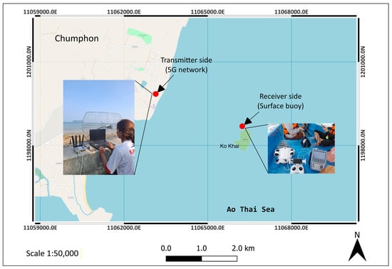
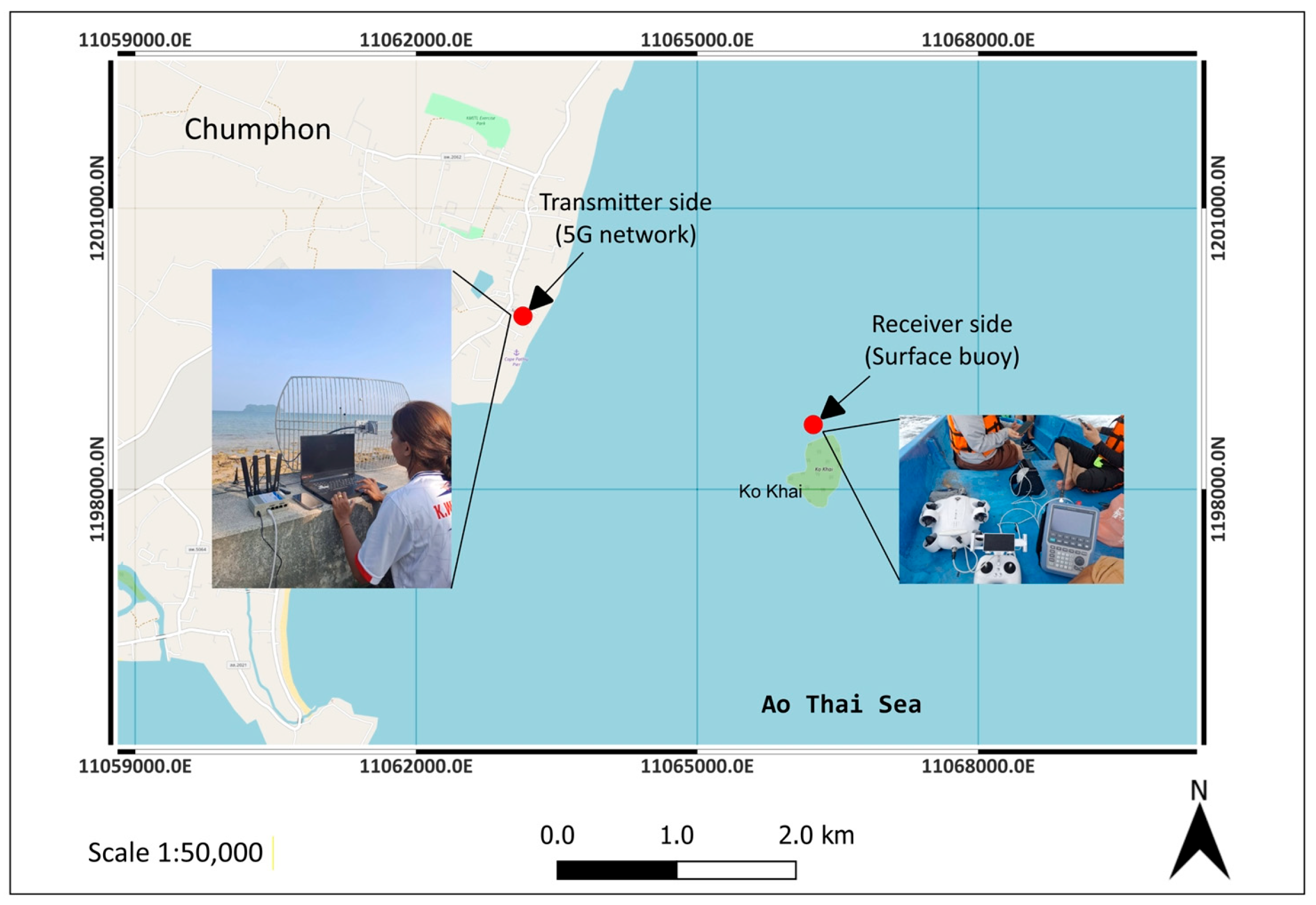
The experiment was conducted at Had Phar-Jom beach on the KMITL Prince of Chumphon campus, spanning both terrestrial and offshore areas in the Ao Thai Sea. Figure 4 shows the geographical layout and field deployment of the experimental setup used to evaluate the proposed drone-enabled hybrid UOC-RF communication system.
Figure 4.
Locations of field experiments in Chumphon province, Thailand.
The onshore transmitter was connected to a commercial 5G network operating at 700 MHz (N28) and 2600 MHz (N44), both licensed in Thailand. It served as the terrestrial 5G access point, where data from the surface gateway were monitored and logged. The transmitter setup included a RUTX50 5G access point, a transmitter antenna, and a host computer that controlled the streaming data. The field experiment was conducted under calm-to-moderate sea conditions, with an estimated wave height below 0.5 m, light winds of approximately 5–8 km/h, and a fixed onshore transmitter antenna at approximately 2 m, ensuring stable maritime propagation during measurements.
The receiver was deployed offshore near Ko Khai as the surface gateway, equipped with an ROV, a spectrum analyzer, a small ship, and a 5G mobile phone for reception. The ROV captured live underwater video, transmitted it via a UOC link to the mobile phone, and then sent the data to the onshore computer host through an RF uplink using RUTX50 equipment. The horizontal distance between the transmitter and receiver was set to 4 km. RSSI measurements and video streaming rates were assessed by varying the video frame rate from 10 to 60 fps during ROV data streaming. Table 2 presents the equipment list and descriptions used in the field test.
Table 2.
Equipment list and descriptions used in the field experiments.
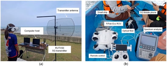
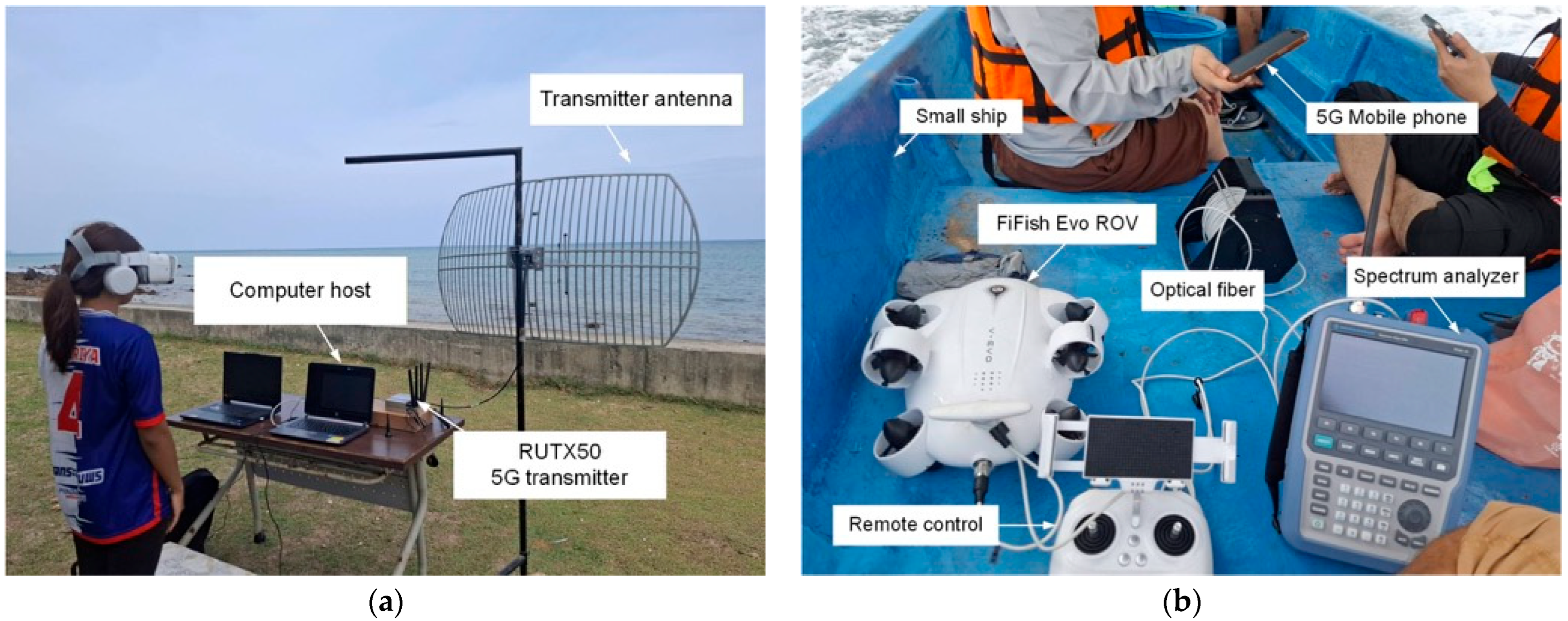
Figure 5a shows the onshore transmitter site, featuring a RUTX50 5G router connected to the transmitter antenna operating in the 700–2600 MHz frequency band. A computer host manages data transmission and records measurement data throughout the experiments. Figure 5b shows the offshore receiver on a small ship that serves as the surface gateway. This setup includes a FiFish EVO ROV, a remote-control unit, and an optical fiber link connecting the ROV to the surface platform for real-time underwater video transmission and control. Onboard, a spectrum analyzer tracks the RSSI and spectral characteristics of the received 5G signal, while a mobile phone uses GPS to pinpoint its position. Note that the ROV depth was set to 15 m at the nearest point to the seabed. The FiFish EVO ROV communicates with a mobile phone via a manufacturer-provided wired optical fiber tether. This link ensures stable high-rate video transmission from the ROV to the surface controller. Since the tether is a physical optical fiber link with negligible packet loss and delay relative to the 5G RF link, it was considered a high-capacity, stable segment in the system model. Therefore, the performance bottleneck analyzed in this study was primarily the 5G RF uplink between the surface gateway and the onshore station. The mobile phone functions as a relay device without performing re-encoding or transcoding. The FiFish application directly forwards the received video stream to the 5G uplink. The measured end-to-end throughput inherently includes any minor processing delay introduced by the mobile device. However, its impact is negligible compared to wireless transmission latency.
Figure 5.
Experimental setups used in the field measurements: (a) onshore 5G transmitter configuration with the RUTX50 router, transmitter antenna, and computer host; (b) offshore surface gateway configuration deployed on a small ship, including the FiFish EVO ROV, optical link, spectrum analyzer, and control devices.
The RSSI was measured at the receiver site using a spectrum analyzer at 700 MHz and 2600 MHz, with video frame rates ranging from 10 fps to 60 fps, yielding varying traffic loads. For each frame rate, the RSSI and average transmission rate were recorded over a consistent observation period to ensure stable data. The reported throughput reflects the actual uplink data rate during real-time video streaming, accounting for protocol overhead and network scheduling. It is important to note that the RSSI measurement was taken during a clear day.
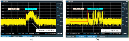
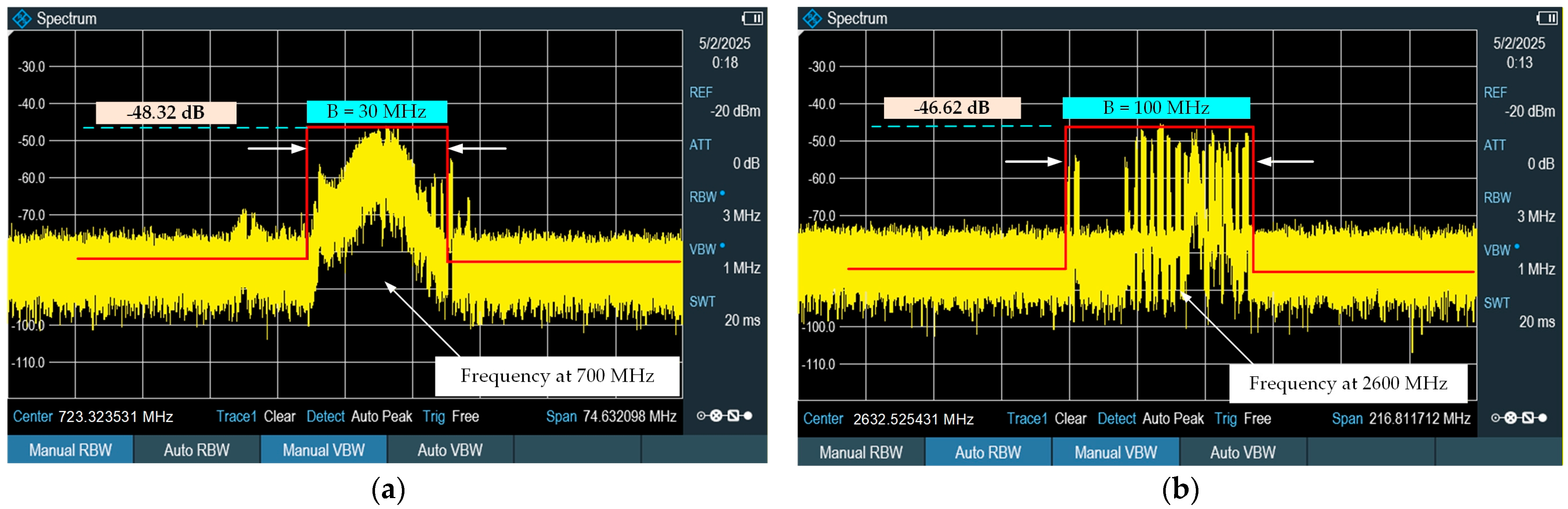
Figure 6a,b shows the measured occupied bandwidth (OBW) of 5G channels at 700 MHz and 2600 MHz, respectively, at the transmitter site (RUTX50), as measured in field experiments with a handheld spectrum analyzer. As shown in Figure 6a, the 700 MHz 5G signal had an effective bandwidth of about 30 MHz, centered on the carrier frequency. The signal level within this occupied band was approximately −48.32 dB, while the out-of-band noise floor was notably lower, indicating clear spectral separation between the signal and noise.
Figure 6.
Measured occupied bandwidth of the 5G channels from the spectrum analyzer measurements: (a) 700 MHz band with an occupied bandwidth of approximately 30 MHz; (b) 2600 MHz band with an occupied bandwidth of approximately 100 MHz.
Conversely, Figure 6b shows that the 5G channel at 2600 MHz spanned approximately 100 MHz, with an in-band signal level of −46.62 dB. The larger spectral occupancy indicates the use of wider channel bandwidths within the mid-band spectrum.
4.2. RSSI Measurement and Analysis
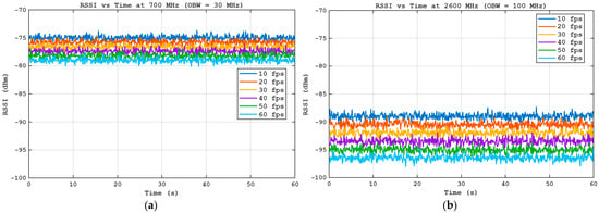
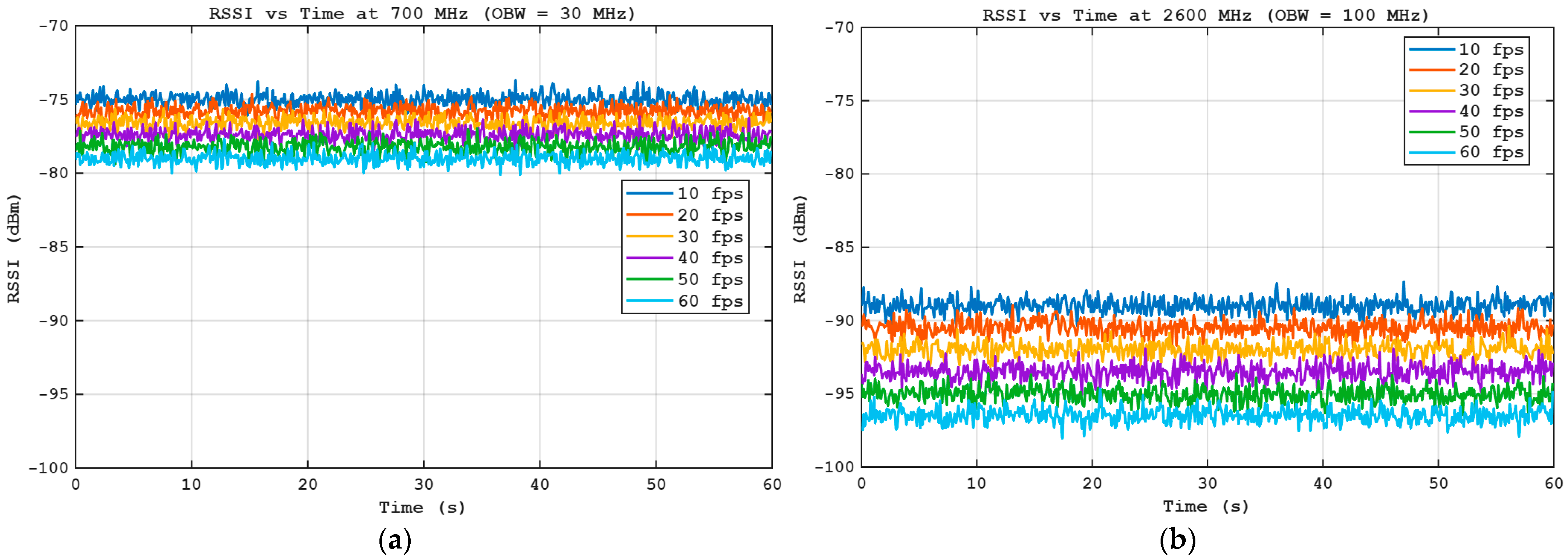
The RSSI measurements at 700 MHz and 2600 MHz are shown in Figure 7a,b, respectively, with the video frame rate varying from 10 fps to 60 fps.
Figure 7.
Measured RSSI versus time at the receiver site for different video frame rates: (a) 700 MHz band; (b) 2600 MHz band.
Figure 7a,b shows the measured RSSI over time at the receiver site for the 700 MHz and 2600 MHz 5G bands, respectively, at video frame rates ranging from 10 fps to 60 fps. The measurements were collected over a 60 s (s) observation interval at a fixed gateway-to-base-station distance of 4 km and an ROV operating depth of 15 m.
As illustrated in Figure 7a, the RSSI at 700 MHz remained relatively stable over time, with average values ranging approximately from −75 dBm at 10 fps to −79 dBm at 60 fps. Although short-term fluctuations were observed due to channel fading and marine environmental dynamics, the overall RSSI degradation with increasing frame rate was gradual. This behavior indicates that the sub-1 GHz band provides robust signal coverage and strong penetration over long-distance maritime links, even under increased uplink traffic load.
In contrast, Figure 7b shows that the RSSI at 2600 MHz was consistently lower and exhibited greater variation than at 700 MHz. The average RSSI decreased from approximately −89 dBm at 10 fps to −96 dBm at 60 fps, indicating a more pronounced sensitivity to higher video frame rates. The steeper RSSI reduction at higher frame rates reflects the combined effects of higher path loss, increased interference, and traffic-dependent resource allocation in the mid-band.
The results in Figure 7a,b confirm that RSSI decreased with increasing video frame rate across both frequency bands, while the 700 MHz band maintained superior signal stability and coverage compared with the 2600 MHz band.
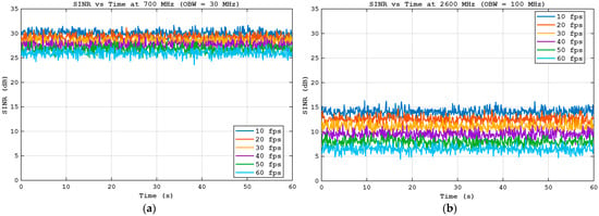
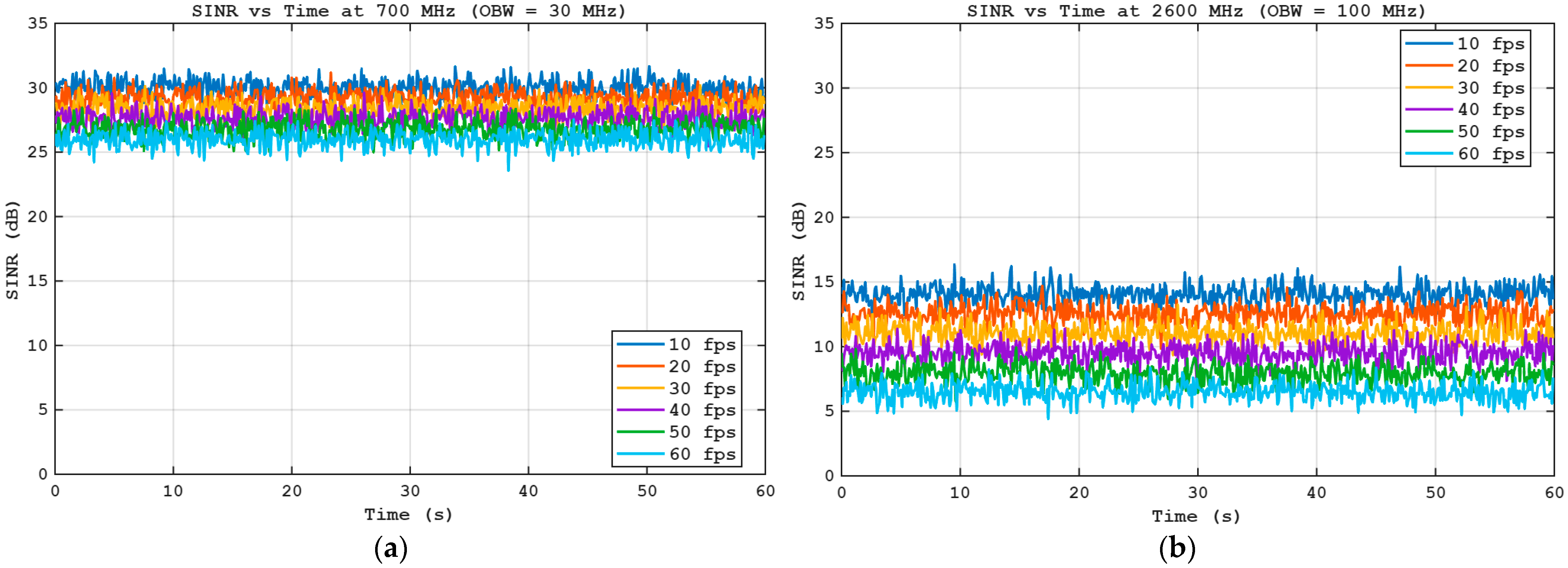
Figure 8a,b illustrates the measured SINR over time for the 700 MHz and 2600 MHz 5G bands, respectively, at video frame rates ranging from 10 fps to 60 fps. The SINR values were derived from the measured in-band RSSI and noise floor within the occupied bandwidths of 30 MHz for 700 MHz and 100 MHz for 2600 MHz.
Figure 8.
Measured SINR versus time at the receiver site for different video frame rates: (a) 700 MHz band; (b) 2600 MHz band.
As shown in Figure 8a, the 700 MHz band achieved relatively high and stable SINR values, with the average SINR decreasing gradually from approximately 30–31 dB at 10 fps to 26–27 dB at 60 fps. Despite short-term fluctuations caused by channel fading and dynamic marine conditions, the SINR remained well above the minimum requirement for reliable real-time video streaming. This behavior highlights the strong interference resilience and favorable propagation characteristics of the sub-1 GHz band in maritime environments.
In contrast, Figure 8b shows that the 2600 MHz band had a significantly lower SINR, with average values ranging from approximately 14–15 dB at 10 fps to 6–7 dB at 60 fps. The SINR degradation became more pronounced as the frame rate increased, reflecting higher path loss, increased interference, and the effects of wider bandwidth allocation at mid-band frequencies. Although the SINR was lower than that of the 700 MHz band, it remained sufficient to support higher throughput when combined with the larger occupied bandwidth.
Overall, the SINR results confirm a clear coverage–capacity trade-off between the two frequency bands: the 700 MHz band provides superior SINR stability and robustness, while the 2600 MHz band offers higher capacity at the expense of lower SINR.
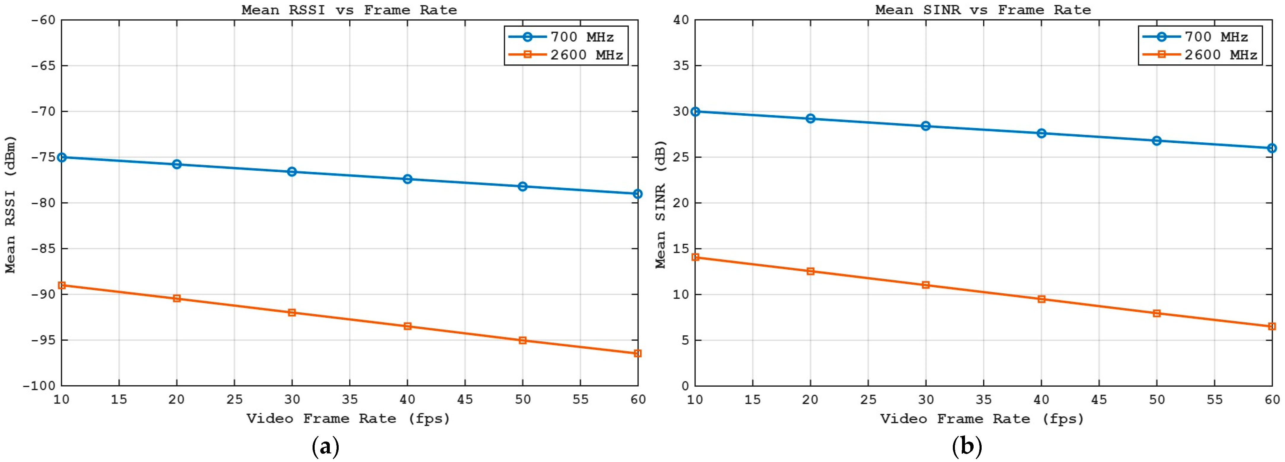
Figure 9a,b shows the mean RSSI and mean SINR, respectively, averaged over the 60-s measurement interval at 700 MHz and 2600 MHz, as a function of video frame rate from 10 fps to 60 fps.
Figure 9.
Mean values of: (a) RSSI; (b) SINR as a function of video frame rate for 700 MHz and 2600 MHz 5G bands.
As shown in Figure 9a, the mean RSSI decreased nearly linearly with increasing video frame rate across both frequency bands. At 700 MHz, the mean RSSI declined from approximately −75 dBm at 10 fps to −79 dBm at 60 fps, whereas at 2600 MHz, it dropped more sharply from approximately −89 dBm to −96 dBm over the same frame-rate range. The consistently higher RSSI at 700 MHz reflects superior propagation characteristics and lower path loss over the long maritime link, whereas the steeper degradation at 2600 MHz highlights greater sensitivity to traffic load and environmental attenuation.
Figure 9b showed a similar trend for the mean SINR, with a gradual reduction as the frame rate increased. The 700 MHz band maintained high SINR values, decreasing from approximately 30 dB at 10 fps to 26 dB at 60 fps, indicating robust interference resilience and stable link quality. In contrast, the 2600 MHz band exhibited a more pronounced SINR degradation, decreasing from approximately 14 dB to 6 dB as the frame rate increased. This reduction was attributed to higher path loss, increased interference, and resource contention associated with wider bandwidth utilization at mid-band frequencies.
Summary: Figure 9a,b quantitatively confirms that higher video frame rates impose additional uplink load, reducing RSSI and SINR, and emphasize the inherent coverage–capacity trade-off between 700 MHz (sub-1 GHz) and 2600 MHz (mid-band) 5G frequencies. Although the 2600 MHz band experiences lower RSSI and SINR, its significantly larger occupied bandwidth enables higher achievable throughput, making it suitable for high-capacity real-time underwater video streaming when sufficient link quality is maintained. Based on the experimental results, stable streaming at 10–30 fps was achievable with approximately 20–30 MHz occupied bandwidth. For high-quality streaming at 50–60 fps, bandwidths above 50 MHz significantly improve performance stability.
4.3. Throughput Analysis
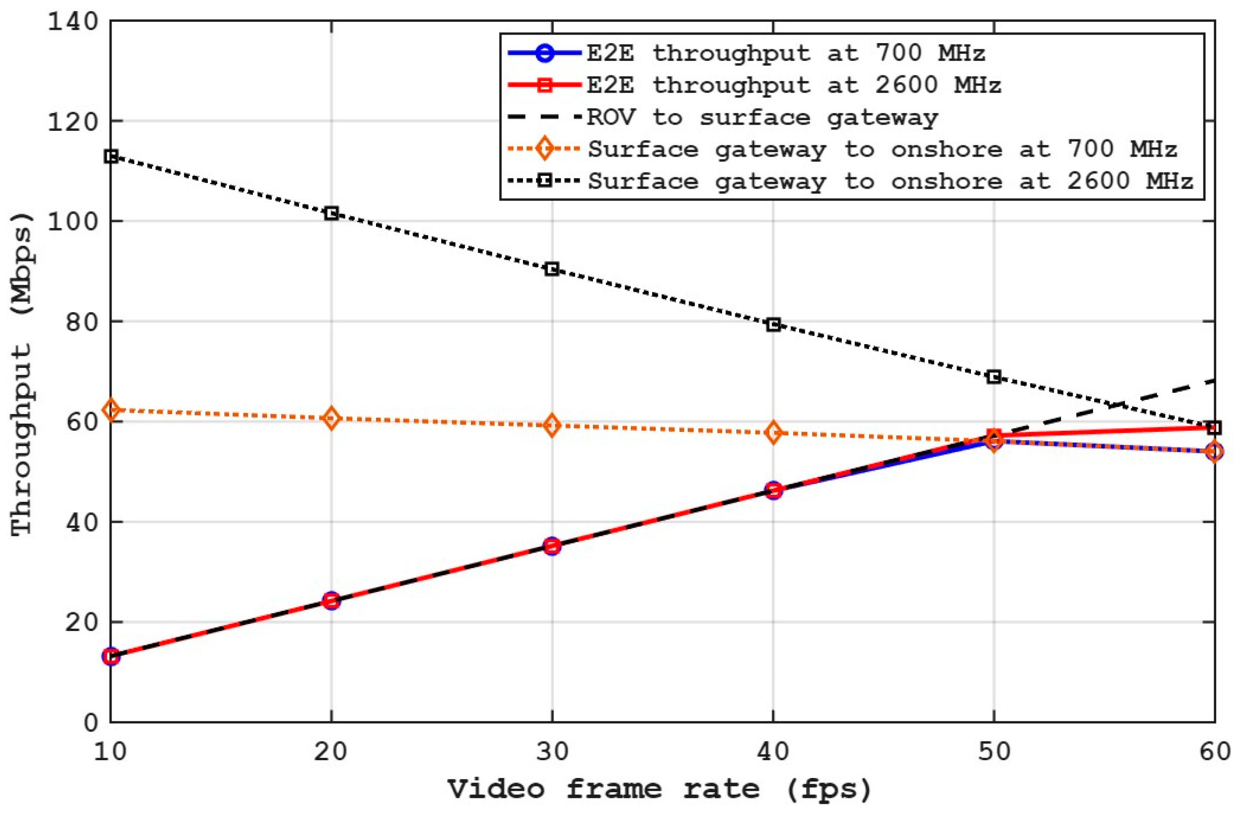
The end-to-end (E2E) throughput can be obtained by substituting (17) into the minimum achievable rate of the UOC-RF link. Figure 10 shows throughput performance as a function of video frame rate for each segment of the proposed communication model, including the ROV-to-surface gateway link, the surface gateway-to-onshore 5G links at 700 MHz and 2600 MHz, and the resulting E2E throughput.
Figure 10.
Throughput versus video frame rate for individual communication segments and the resulting end-to-end (E2E) throughput, including the ROV-to-surface gateway fiber link and the surface gateway-to-onshore 5G links at 700 MHz and 2600 MHz.
The ROV-to-surface gateway throughput, implemented via a 15 m optical fiber tether, increased almost linearly with the video frame rate. The black dot line graph shows a direct relationship between frame rate and required video data rate, indicating that the fiber link can support higher throughput without significant degradation. In contrast, the surface gateway-to-onshore 5G links exhibited different trends across operating frequency bands. For the 700 MHz band, as shown by the red diamond dot line, the achievable throughput remained relatively stable, decreasing only slightly as the frame rate increased. This stability was attributed to the higher RSSI and SINR observed at sub-1 GHz frequencies, which provide robust long-range maritime coverage but are constrained by the approximately 30 MHz of occupied bandwidth.
In the 2600 MHz band, as shown by the black square-dot line, 5G throughput was significantly higher at low frame rates due to approximately 100 MHz of occupied bandwidth. However, as the frame rate increased, throughput gradually decreased because of SINR degradation, higher path loss, and increased uplink traffic load. This behavior highlights the greater sensitivity of mid-band frequencies to channel conditions and traffic intensity.
The E2E throughput curves closely followed the minimum throughput across the individual segments, consistent with substituting (17). At lower frame rates, the E2E throughput was primarily limited by the required video data rate rather than the wireless link capacity. As the frame rate increased, the E2E throughput became constrained by the 5G uplink, particularly at 700 MHz due to bandwidth limitations and at 2600 MHz due to SINR degradation. Beyond approximately 50 fps, the E2E throughput saturated and then slightly decreased, indicating the onset of the wireless bottleneck.
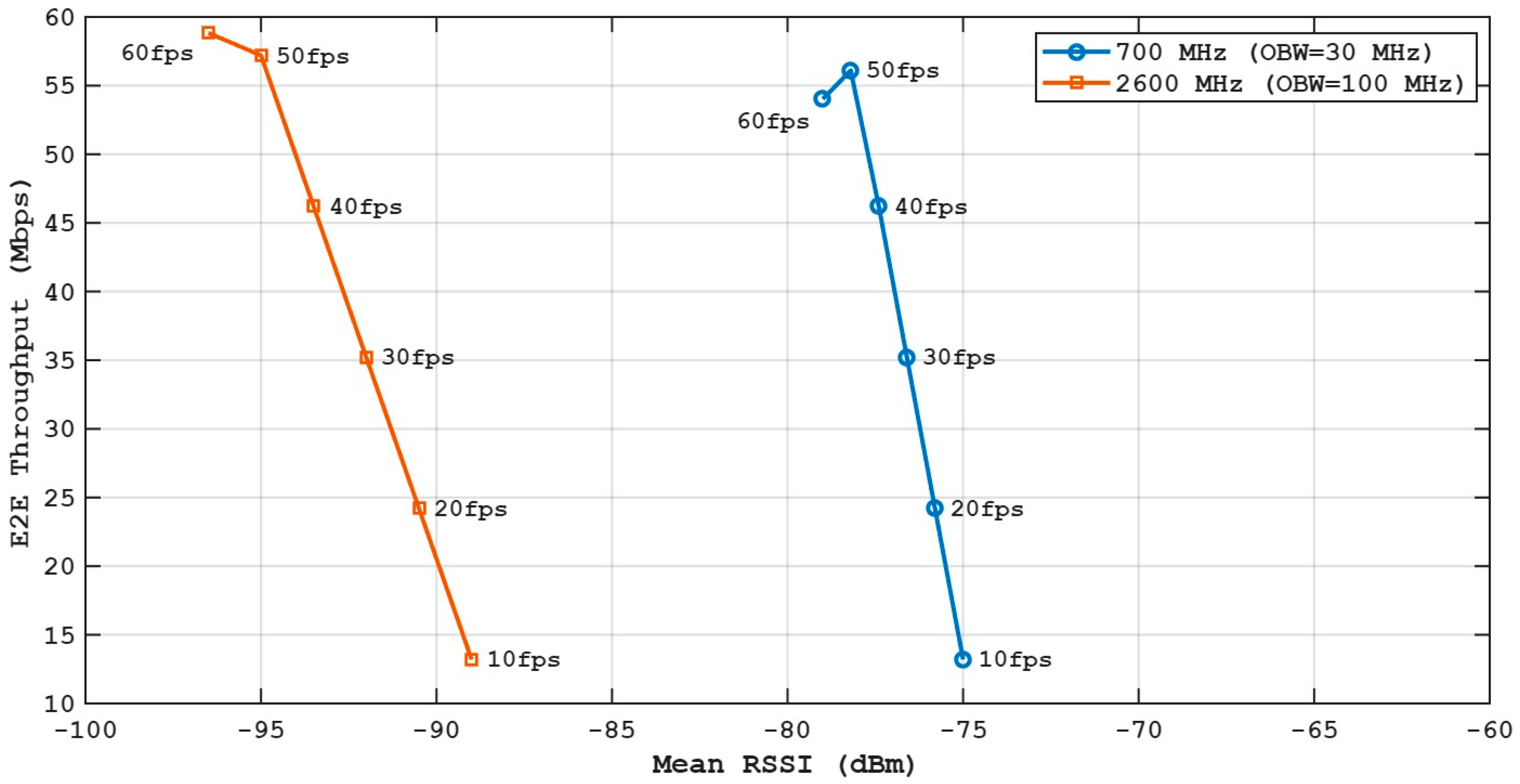
Figure 11 shows the relationship between E2E throughput and mean RSSI for the 700 MHz and 2600 MHz 5G bands across video frame rates from 10 fps to 60 fps. Each point represents a specific frame rate, highlighting how variations in received signal strength affect the achievable E2E transmission rate.
Figure 11.
End-to-end (E2E) throughput versus mean RSSI for 700 MHz (30 MHz bandwidth) and 2600 MHz (100 MHz bandwidth) under different video frame rates.
In the 700 MHz band, E2E throughput rose as the average RSSI improved from roughly −75 dBm to −79 dBm, reaching around 55–56 Mbps at higher frame rates. Although it used a narrow 30 MHz bandwidth, the 700 MHz band maintained strong RSSI due to favorable propagation conditions in maritime settings. This results in consistent throughput across a broad RSSI range, indicating that E2E performance is primarily limited by bandwidth rather than signal strength.
In contrast, the 2600 MHz band operated at significantly lower RSSI levels, ranging from approximately −90 dBm to −97 dBm, yet achieved comparable or even higher E2E throughput at higher frame rates. This behavior is enabled by the substantially wider 100 MHz occupied bandwidth, which compensates for the reduced signal strength. However, the steeper slope of the 2600 MHz curve indicates that throughput is more sensitive to RSSI degradation, reflecting the greater impact of path loss and interference at mid-band frequencies.
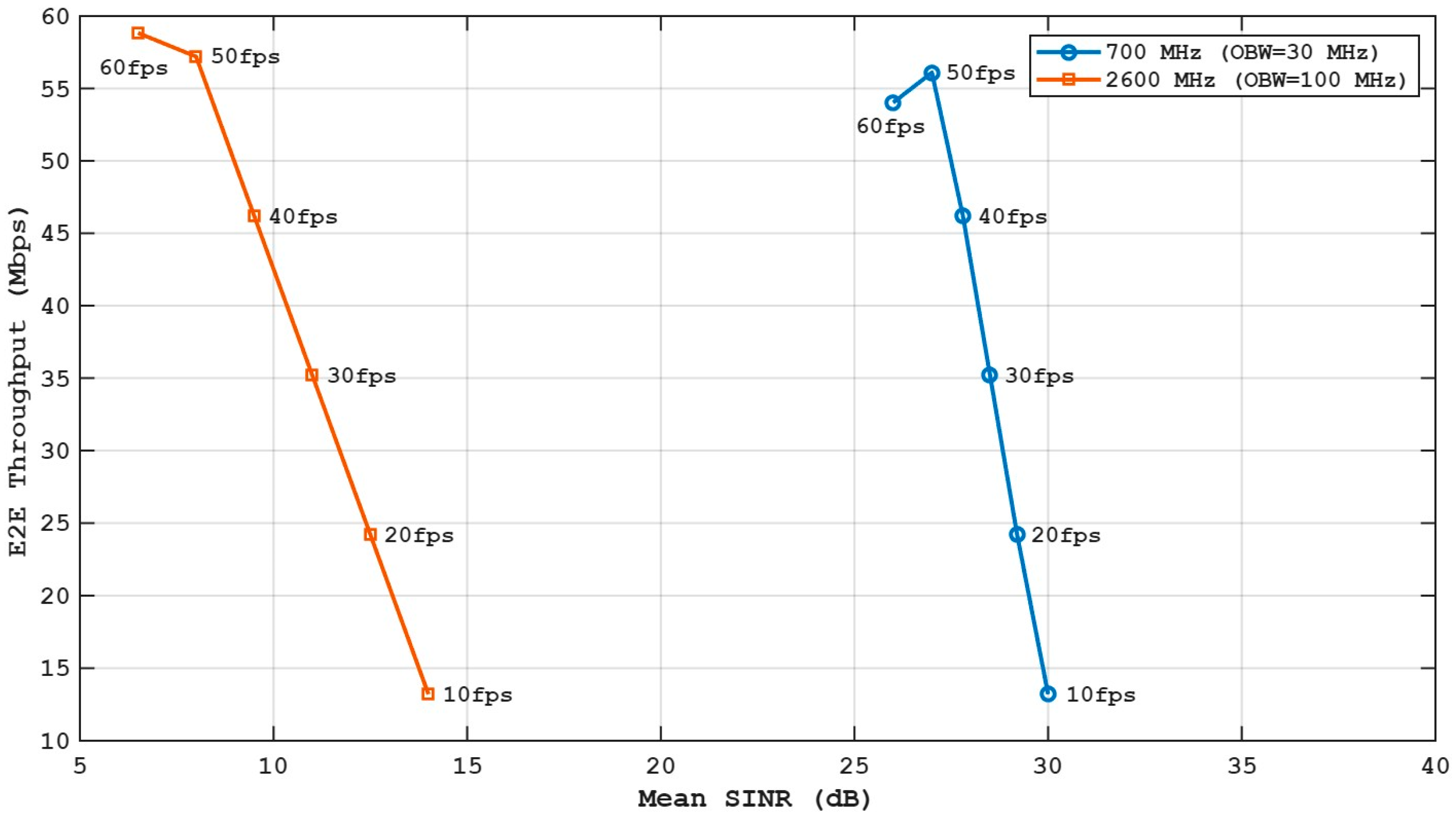
Figure 12 shows the relationship between E2E throughput and mean SINR for the 700 MHz and 2600 MHz 5G bands under video frame rates from 10 fps to 60 fps. Each marker corresponds to a specific frame rate, illustrating how link quality governs achievable throughput in the hybrid UOC-RF system.
Figure 12.
End-to-end (E2E) throughput versus mean SINR for 700 MHz (30 MHz bandwidth) and 2600 MHz (100 MHz bandwidth) under different video frame rates.
In the 700 MHz band, SINR levels of 25–30 dB were observed due to favorable propagation conditions and reduced path loss in maritime settings. As SINR improved, E2E throughput increased from approximately 13 Mbps at 10 fps to approximately 55 Mbps at 50 fps, then to 56 Mbps at 60 fps, and finally to 60 Mbps at 60 fps. The curve showed gradual saturation at higher SINR, indicating that throughput becomes bandwidth-limited rather than SINR-limited, which aligns with substitution (17).
In contrast, the 2600 MHz band had much lower SINR levels, roughly 6–14 dB, because of higher path loss and more interference. Despite this SINR disadvantage, its broader bandwidth enables similar end-to-end throughput of 58–60 Mbps at higher frame rates. Nevertheless, the sharper increase in the 2600 MHz curve indicates that throughput is more sensitive to changes in SINR; even small decreases in SINR cause a noticeable drop in throughput.
Comparing both bands revealed a clear robustness-capacity trade-off. The 700 MHz band offers high SINR stability and reliable throughput over long distances, making it suitable for persistent marine observation and control links. Meanwhile, the 2600 MHz band offers higher capacity scalability due to its bandwidth, but requires sufficient SINR margins to sustain high-frame-rate video streaming.
The experimental throughput results are consistent with the proposed analytical framework described in substitution (17), where the E2E transmission rate is governed by the minimum achievable rate between the optical tether and the 5G uplink. Since the fiber link provides stable high-capacity transmission, the E2E performance is primarily determined by the RF segment, which follows a Shannon-type relationship proportional to . As observed in Figure 10, Figure 11 and Figure 12, the 700 MHz band operated in a bandwidth-limited regime at high SINR, while the 2600 MHz band exhibited SINR-dependent throughput behavior due to its wider bandwidth and lower signal margin. The close agreement between analytical trends and measured E2E throughput validates the modeling approach and confirms its applicability for predicting drone-enabled maritime communication performance.
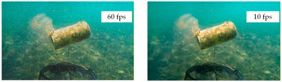
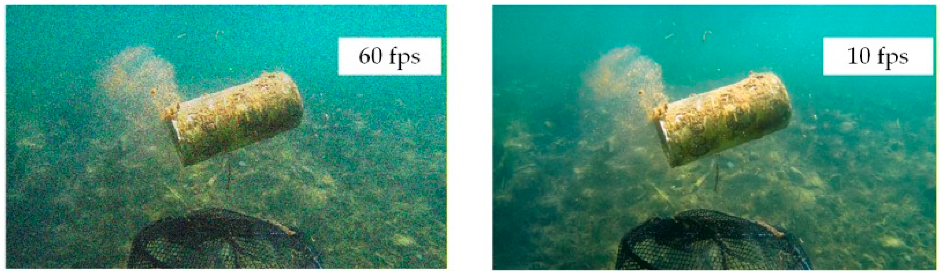
To further illustrate the impact of frame rate on perceived video quality, Figure 13 shows representative snapshot frames captured at the onshore computer host under 700 MHz-band transmissions at 10 fps and 60 fps. Both images were recorded under identical environmental and channel conditions at an approximately 4 km transmission distance and 15 m ROV depth.
Figure 13.
Representative onshore snapshots at 700 MHz comparing real-time underwater video streaming at 60 fps and 10 fps under identical maritime conditions.
At 10 fps, the video stream maintained stable transmission with relatively lower data demand, resulting in smooth rendering and moderate motion representation. In contrast, the 60 fps configuration generated a significantly higher data rate, increasing the load on the 5G uplink. Although a higher frame rate enhanced motion continuity and temporal resolution, the increased transmission demand resulted in slight visual degradation due to throughput saturation and SINR-dependent limitations, as shown in Figure 11 and Figure 12.
Table 3 quantitatively compares the two frequency bands and confirms that system performance is governed by a clear coverage–capacity trade-off of real-time video streaming: the 700 MHz band achieved higher RSSI and SINR stability due to favorable propagation characteristics, whereas the 2600 MHz band, despite lower link robustness, attained a higher peak throughput due to its significantly wider occupied bandwidth. These results reinforce the analytical interpretation presented in Figure 10, Figure 11 and Figure 12.
Table 3.
Summarizes the quantitative differences between the 700 MHz and 2600 MHz 5G operation in maritime conditions, clearly illustrating the experimental observation of real-time video streaming via UOC-RF communication.
4.4. Discussion
To discuss the experimental results of the proposed drone-enabled hybrid UOC-RF communication system and highlight the key benefits for real-time underwater video streaming in marine observation scenarios, the results showed that RSSI, SINR, bandwidth availability, and video frame rate jointly affect E2E throughput.
Figure 7a,b shows RSSI measurements that confirm that the 700 MHz band consistently delivered a stronger received signal strength than the 2600 MHz band under identical transmission conditions. This behavior was attributed to lower free-space path loss and improved diffraction over the sea surface, both of which are critical advantages for long-distance maritime links. As the video frame rate increased from 10 fps to 60 fps, a gradual RSSI degradation was observed in both bands due to increased data load and higher transmission activity. However, the RSSI degradation at 700 MHz remained moderate, enabling a stable link operation even at higher frame rates.
In contrast, the 2600 MHz band exhibited lower RSSI, indicating greater susceptibility to path loss and environmental interference. Despite this limitation, the 2600 MHz band remained operational because its substantially larger occupied bandwidth compensates for reduced signal strength.
The SINR results in Figure 8a underscore the robustness of the 700 MHz band. High SINR values exceeding 25 dB were maintained across all frame rates, ensuring reliable demodulation and low error probability. This characteristic makes the 700 MHz band particularly suitable for mission-critical control signaling and long-duration marine observation tasks. In contrast, the 2600 MHz band operated at lower SINR levels, typically below 15 dB. The observed reduction in SINR with increasing frame rate highlights the sensitivity of mid-band frequencies to interference and noise in maritime environments. Nevertheless, the system remains capable of supporting real-time video streaming due to the higher spectral resources available in this band.
The latency contribution is primarily due to 5G uplink scheduling and network processing, rather than to the ROV-to-surface optical link, which introduces negligible delay. These findings indicate that while throughput determines video quality and frame smoothness, latency is governed mainly by wireless resource allocation and link quality. Future work will include a more comprehensive characterization of latency under varying maritime dynamics and mobility conditions.
The E2E throughput analysis showed that the proposed UOC-RF communication system effectively decouples the constraints of underwater and surface communication. The ROV-to-surface gateway link, implemented via optical fiber, provides a stable, high-capacity underwater segment, eliminating the uncertainty associated with acoustic or optical wireless channels. As a result, overall system performance is primarily governed by the surface gateway-to-onshore 5G link, enabling the direct application of terrestrial 5G optimization strategies in marine environments.
The results further highlight the fundamental trade-off between sub-GHz and mid-band 5G frequencies: the 700 MHz band provides superior coverage robustness and higher link stability due to lower path loss, whereas the 2600 MHz band enables higher spectral capacity through a wider occupied bandwidth but with reduced propagation resilience in maritime environments.
To this end, it highlights that the proposed hybrid UOC-RF system offers a scalable, reliable, and high-performance communication solution for underwater drones, bridging underwater exploration and terrestrial 5G infrastructure. This makes the approach particularly attractive for applications such as marine monitoring, underwater inspection, smart tourism, and environmental surveillance.
5. Conclusions
This paper has proposed an experimental analysis of RSSI, SINR, and E2E throughput for a drone-enabled hybrid UOC-RF communication system supporting real-time underwater video streaming. The proposed system architecture combines an underwater ROV, a surface gateway, and a 5G terrestrial network to support seamless data transfer from the underwater environment to the onshore network.
Experimental results from offshore experiments have shown that the choice of 5G frequency is critical to the performance of underwater drone communication systems. The 700 MHz frequency offers better RSSI and SINR with its favorable propagation properties, which support reliable and robust connectivity over long ranges. On the other hand, the 2600 MHz frequency, with its relatively lower RSSI and SINR, offers higher peak throughput with its vastly larger occupied bandwidth. These results show that the availability of bandwidth can compensate for moderate signal degradation, especially for high-throughput video streaming applications.
The E2E throughput analysis verified the proposed analytical model and showed that the hybrid UOC-RF communication system can successfully separate underwater transmission from surface and terrestrial communication. By employing a high-speed optical link between the ROV and surface gateway, the system performance is mainly constrained by the 5G RF link, which enables the direct application of terrestrial wireless optimization methods in marine environments.
In the future, path loss models, latency analysis, and multi-distance and multi-depth experiments for drone-enabled hybrid UOC-RF communication in maritime environments will be developed. The model will consider sea surface reflections, antenna types, ROV depth and distance, frequency-dependent attenuation, and environmental changes to improve the accuracy of system performance prediction and design.
Funding
This research is a result of the project entitled “Development of innovative underwater drone and virtual reality (VR) technology for driving a smart marine tourism industrial in Thailand”, Grant No. RE-KRIS/FF67/050 by King Mongkut’s Institute of Technology Ladkrabang (KMITL), which has received funding support from the NSRF.
Data Availability Statement
The data presented in this study are available from the corresponding author upon request.
Conflicts of Interest
The authors declare no conflicts of interest.
References
- Wang, J.; Zhou, K.; Xing, W.; Li, H.; Yang, Z. Applications, evolutions, and challenges of drones in maritime transport. J. Mar. Sci. Eng. 2023, 11, 2056. [Google Scholar] [CrossRef] [Scilit]
- Duangsuwan, S.; Klubsuwan, K. Underwater drone-enabled wireless communication systems for smart marine communications: A study of enabling technologies, opportunities, and challenges. Drones 2025, 9, 784. [Google Scholar] [CrossRef] [Scilit]
- Theocharidis, T.; Kavallieratou, E. Underwater communication technologies: A review. Telecommun. Syst. 2025, 88, 54. [Google Scholar] [CrossRef] [Scilit]
- Liu, S.; Zhu, L.; Huang, F.; Hassan, A.; Wang, D.; He, Y. A survey on air-to-sea integrated maritime internet of things: Enabling technologies, applications, and future challenges. J. Mar. Sci. Eng. 2023, 12, 11. [Google Scholar] [CrossRef] [Scilit]
- Dai, M.; Dou, C.; Wu, Y.; Qian, L.; Lu, R.; Quek, T.Q. Multi-UAV aided multi-access edge computing in marine communication networks: A joint system-welfare and energy-efficient design. IEEE Trans. Commun. 2024, 72, 5517–5531. [Google Scholar] [CrossRef] [Scilit]
- Agheli, P.; Beyranvand, H.; Emadi, M.J. UAV-assisted underwater sensor networks using RF and optical wireless links. J. Light. Technol. 2021, 39, 7070–7082. [Google Scholar] [CrossRef] [Scilit]
- Rafiq, G.; Bose, P.; Orten, P. 5G cellular communication for maritime applications. IEEE Access 2025, 13, 109451–109472. [Google Scholar] [CrossRef] [Scilit]
- Butcher, P.A.; Colefax, A.P.; Gorkin, R.A., III; Kajiura, S.M.; López, N.A.; Mourier, J.; Purcell, C.R.; Skomal, G.B.; Tucker, J.P.; Walsh, A.J.; et al. The drone revolution of shark science: A review. Drones 2021, 5, 8. [Google Scholar] [CrossRef] [Scilit]
- Dai, M.; Li, Y.; Li, P.; Wu, Y.; Qian, L.; Lin, B.; Su, Z. A survey on integrated sensing, communication, and computing networks for smart oceans. J. Sens. Actuator Netw. 2022, 11, 70. [Google Scholar] [CrossRef] [Scilit]
- Qu, Z.; Lai, M. A review on electromagnetic, acoustic, and new emerging technologies for submarine communication. IEEE Access 2024, 12, 12110–12125. [Google Scholar] [CrossRef] [Scilit]
- Alahmad, R.; Alraie, H.; Hasaba, R.; Eguchi, K.; Matsushima, T.; Fukumoto, Y.; Ishii, K. Performance analysis of underwater radiofrequency communication in seawater: An experimental study. J. Mar. Sci. Eng. 2024, 12, 2104. [Google Scholar] [CrossRef] [Scilit]
- Li, Z.; Li, W.; Sun, K.; Fan, D.; Cui, W. Recent progress on underwater wireless communication methods and applications. J. Mar. Sci. Eng. 2025, 13, 1505. [Google Scholar] [CrossRef] [Scilit]
- Petritoli, E.; Leccese, F. Autonomous underwater glider: A comprehensive review. Drones 2024, 9, 21. [Google Scholar] [CrossRef] [Scilit]
- Alqurashi, F.S.; Trichili, A.; Saeed, N.; Ooi, B.S.; Alouini, M.S. Maritime communications: A survey on enabling technologies, opportunities, and challenges. IEEE Internet Things J. 2022, 10, 3525–3547. [Google Scholar] [CrossRef] [Scilit]
- Hasan, K.; Ahmad, S.; Liaf, A.F.; Karimi, M.; Ahmed, T.; Shawon, M.A.; Mekhilef, S. Oceanic challenges to technological solutions: A review of autonomous underwater vehicle path technologies in biomimicry, control, navigation, and sensing. IEEE Access 2024, 12, 46202–46231. [Google Scholar] [CrossRef] [Scilit]
- Haziq, M.; Phung, Q.V.; Lachowicz, S.; Habibi, D.; Ahmad, I. Modulation techniques for underwater acoustic communication: A comprehensive survey. IEEE Access 2025, 13, 150715–150755. [Google Scholar] [CrossRef] [Scilit]
- Huang, J.; Diamant, R. Adaptive modulation for long-range underwater acoustic communication. IEEE Trans. Wirel. Commun. 2020, 19, 6844–6857. [Google Scholar] [CrossRef] [Scilit]
- Wei, D.; Yan, L.; Huang, C.; Wang, J.; Chen, J.; Pan, M.; Fang, Y. Dynamic magnetic induction wireless communications for autonomous-underwater-vehicle-assisted underwater IoT. IEEE Internet Things J. 2020, 7, 9834–9845. [Google Scholar] [CrossRef] [Scilit]
- Cai, W.; Liu, Z.; Zhang, M.; Lv, S.; Wang, C. Cooperative formation control for multiple AUVs with intermittent underwater acoustic communication in IoUT. IEEE Internet Things J. 2023, 10, 15301–15313. [Google Scholar] [CrossRef] [Scilit]
- Sun, K.; Li, Y.; Han, Z. Research on underwater wireless optical communication channel model and Its application. Appl. Sci. 2023, 14, 206. [Google Scholar] [CrossRef] [Scilit]
- Zhilin, I.V.; Bushnaq, O.M.; De Masi, G.; Natalizio, E.; Akyildiz, I.F. A universal multimode (acoustic, magnetic induction, optical, RF) software defined modem architecture for underwater communication. IEEE Trans. Wirel. Commun. 2023, 22, 9105–9116. [Google Scholar] [CrossRef] [Scilit]
- Onasami, O.; Feng, M.; Xu, H.; Haile, M.; Qian, L. Underwater acoustic communication channel modeling using reservoir computing. IEEE Access 2022, 10, 56550–56563. [Google Scholar] [CrossRef] [Scilit]
- Kaushal, H.; Kaddoum, G. Underwater optical wireless communication. IEEE Access 2016, 4, 1518–1547. [Google Scholar] [CrossRef] [Scilit]
- Li, S.; Yang, L.; da Costa, D.B.; Yu, S. Performance analysis of UAV-based mixed RF-UWOC transmission systems. IEEE Trans. Commun. 2021, 69, 5559–5572. [Google Scholar] [CrossRef] [Scilit]
- Nkenyereye, L.; Nkenyereye, L.; Ndibanje, B. Internet of underwater things: A survey on simulation tools and 5G-based underwater networks. Electronics 2024, 13, 474. [Google Scholar] [CrossRef] [Scilit]
- Wibisono, A.; Piran, M.J.; Song, H.K.; Lee, B.M. A survey on unmanned underwater vehicles: Challenges, enabling technologies, and future research directions. Sensors 2023, 23, 7321. [Google Scholar] [CrossRef] [Scilit]
- Mao, R.; Li, Y.; Li, G.; Hildre, H.P.; Zhang, H. A systematic survey of digital twin applications: Transferring knowledge from automotive and aviation to maritime industry. IEEE Trans. Intell. Transp. Syst. 2025, 26, 4240–4259. [Google Scholar] [CrossRef] [Scilit]
- Luo, H.; Wang, X.; Bu, F.; Yang, Y.; Ruby, R.; Wu, K. Underwater real-time video transmission via wireless optical channels with swarms of AUVs. IEEE Trans. Vehicular Tech. 2023, 72, 14688–14703. [Google Scholar] [CrossRef] [Scilit]
- Huang, J.; Wang, C.X.; Yang, Y.; Liu, Y.; Sun, J.; Zhang, W. Channel measurements and modeling for 400–600-MHz bands in urban and suburban scenarios. IEEE Internet Things J. 2020, 8, 5531–5543. [Google Scholar] [CrossRef] [Scilit]
- Shakya, D.; Ying, M.; Rappaport, T.S.; Poddar, H.; Ma, P.; Wang, Y.; Al-Wazani, I. Propagation Measurements and Channel Models in Indoor Environment at 6.75 GHz FR1 (C) and 16.95 GHz FR3 Upper-mid band Spectrum for 5G and 6G. In Proceedings of the IEEE Global Communications Conference, Cape Town, South Africa, 8–12 December 2024. [Google Scholar]
- Wang, J.; Zhou, H.; Li, Y.; Sun, Q.; Wu, Y.; Jin, S.; Quek, T.Q.S.; Xu, C. Wireless channel models for maritime communications. IEEE Access 2018, 6, 68070–68088. [Google Scholar] [CrossRef] [Scilit]
- Dahman, G.; Couillard, D.; Grandmaison, M.E.; Poitau, G.; Gagnon, F. Improved 2-ray model for overwater propagation channels: Modeling the instantaneous variations in the received signal strength. IEEE Wirel. Commun. Lett. 2019, 8, 865–868. [Google Scholar] [CrossRef]
- Mi, Y.; Zhang, X.; Kong, L.; Wang, Y.; Ma, D.; Xiao, P.; Wei, J. Measurement-based characterization and modeling of land-to-ship wireless channels at 3.2 GHz. IEEE Trans. Antennas Propag. 2025, 73, 441–452. [Google Scholar] [CrossRef] [Scilit]
- Zayed, M.M.; Shokair, M. Modeling and simulation of optical wireless communication channels in IoUT considering water types turbulence and transmitter selection. Sci. Rep. 2025, 15, 28381. [Google Scholar] [CrossRef] [Scilit]
- Ramley, I.; Alzayed, H.M.; Al-Hadeethi, Y.; Chen, M.; Barasheed, A.Z. An overview of underwater optical wireless communication channel simulations with a focus on the Monte Carlo method. Mathematics 2024, 12, 3904. [Google Scholar] [CrossRef] [Scilit]
- Duangsuwan, S.; Jamjareegulgarn, P. Exploring ground reflection effects on received signal strength indicator and path loss in far-field air-to-air for unmanned aerial vehicle-enabled wireless communication. Drones 2024, 11, 677. [Google Scholar] [CrossRef] [Scilit]
- Zayed, M.M.; Shokair, M.; Elagooz, S.; Elshenawy, H. A more detailed mathematical model for analyzing the link budget in UWOCs for both LoS and N-LoS scenarios. J. Opt. 2024, 1–29. [Google Scholar] [CrossRef] [Scilit]

Disclaimer/Publisher’s Note: The statements, opinions and data contained in all publications are solely those of the individual author(s) and contributor(s) and not of MDPI and/or the editor(s). MDPI and/or the editor(s) disclaim responsibility for any injury to people or property resulting from any ideas, methods, instructions or products referred to in the content. |
© 2026 by the author. Licensee MDPI, Basel, Switzerland. This article is an open access article distributed under the terms and conditions of the Creative Commons Attribution (CC BY) license.