Article

A Modular 3D-Printed Ducted-Fan Platform for Advanced Autonomy Research: From Design to Flight Test


by
Andrea Dan Ryals
,
Michael Alibani
,
Gianpaolo Lantermo
,
Mariangela Menolotto
,
Stefano Maugeri
and
Lorenzo Pollini
*,†
Department of Information Engineering, Via Caruso 16, 56017 Pisa, Italy
*
Author to whom correspondence should be addressed.
These authors contributed equally to this work.
Drones 2026, 10(3), 165; https://doi.org/10.3390/drones10030165
Submission received: 29 December 2025 / Revised: 20 February 2026 / Accepted: 23 February 2026 / Published: 27 February 2026

Highlights

What are the main findings?
  • Fully 3D-printed UAV design: A ducted-fan UAV can be built entirely from 3D-printed components and off-the-shelf motors and electronics, achieving stable flight. The modular design enables rapid prototyping and easy part replacement.
  • Sufficient aerodynamic performance: Custom 3D-printed propellers and ducts deliver sufficient performance, with experiments confirming that operating within a duct amplifies thrust compared to a single propeller in free air.
What are the implications of the main findings?
  • Accessibility for low-budget research: The design methodology lowers barriers for labs with limited resources to conduct advanced UAVs research, especially in autonomy and control.
  • Rapid experimentation: The modular architecture enables quick testing of different UAVs configurations, control strategies, and sensor payloads.

Abstract

Following the growing interest in small-scale unmanned aerial vehicles (UAVs), this paper presents a comprehensive conceptual design methodology for a modular ducted-fan aerial vehicle intended for research applications. Although ducted-fan configurations offer significant advantages over conventional multirotor platforms, particularly in urban, indoor, and human-interaction scenarios, the availability of affordable and customizable ducted-fan UAVs platforms suitable for scientific research remains limited. To address this gap, the paper details the complete design of the vehicle, including propeller aerodynamics and duct design, mechanical structure, actuation system, dynamic modeling, and control strategy. All major structural and aerodynamic components are fabricated using low-cost additive manufacturing, enabling rapid prototyping and high modularity. The vehicle’s performance is experimentally assessed through bench tests and indoor flight experiments, demonstrating stable flight and satisfactory attitude control. The presented work shows that a fully functional ducted-fan UAVs can be realized using commercial off-the-shelf electronics and exclusively 3D-printed components, and provides practical guidelines to replicate and adapt the proposed platform for advanced research in UAVs control, navigation, and autonomy.

1. Introduction

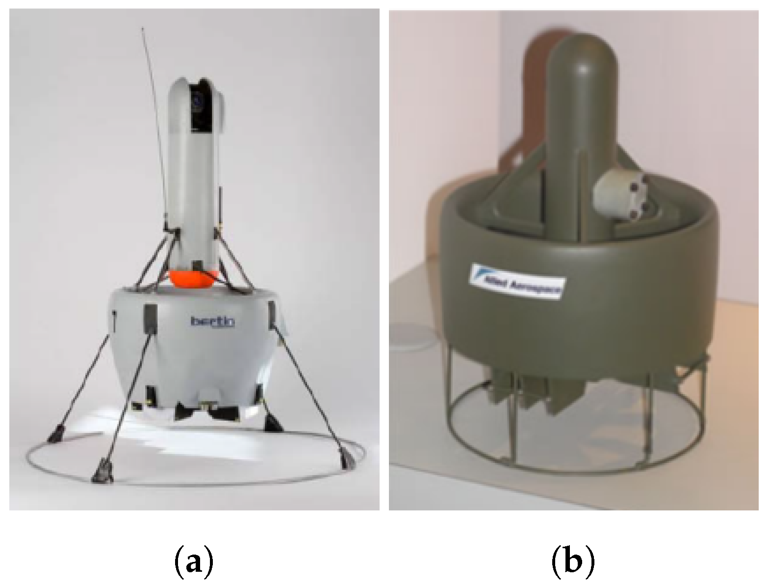
UAVs are currently widespread in a large range of applications, and their market has shown constant growth during the last decade [1,2,3]. Such vehicles proved to be suitable for a wide variety of missions, including aerial photography, surveillance, recognition, and search and rescue. UAVs platforms are mainly subdivided into two categories, fixed-wing and rotary-wing. Fixed-wing UAVs usually have an excellent payload capacity and cruising speed, but present the drawback of requiring runways for take-off and landing, and cannot be used in a confined environment or to fly near obstacles and buildings. Rotorcraft UAVs have the ability of vertical take-off and landing, which removes the need for large areas or infrastructures suited for this purpose, and they also have a unique hovering capability; these two features bring much-enhanced versatility in many operational scenarios. Rotorcraft UAVs are mostly represented by small-scale helicopters and by the large family of multirotors. However, another interesting configuration is the ducted-fan rotorcraft; two representative examples of this category of UAVs are shown in Figure 1. Such a UAV configuration has proven to have good flying abilities in both outdoor and indoor environments. However, the main advantages appear in indoor enclosed spaces, urban environments, and in the presence of obstacles [4,5]. Multirotor and helicopter UAVs have unprotected propellers which, in the event of a collision with an obstacle, represent a critical failure mode of the UAV; on the other hand, ducted-fan UAVs result in a robust solution in the event of a collision with an obstacle due to the intrinsic protection offered to propellers by the duct structure. An enclosed propeller also increases safety in the event of a collision between the UAV and a human, likely to happen especially in indoor situations, where human presence during operations is potentially possible. Recent work has also highlighted ducted-fan UAVs as an enabling platform for safe physical interaction with humans, thanks to the intrinsic rotor shielding provided by the ducted configuration. In particular, a coaxial ducted-fan design has demonstrated stable flight and direct in-flight payload exchange with a human operator, supporting closer and safer human–UAV collaboration [6].
Ducted-fan UAVs have historically been developed primarily for military and tactical applications, where compactness, rotor protection, and robustness in cluttered environments are critical design requirements [7]. Several operational platforms employ ducted propulsion for close-range reconnaissance and operations in confined or hazardous areas, demonstrating the advantages of shrouded rotors for survivability and safety [8,9]. However, despite these technical benefits, civil ducted-fan UAVs remain relatively rare on the commercial market. Compared to conventional multirotor drones, fully ducted configurations are typically more complex and less efficient, which has limited their widespread adoption in cost-sensitive civil applications. Only a few specialized systems, mainly designed for industrial inspection or hazardous environment operation, are currently available, and these are generally high-cost, mission-specific platforms. Consequently, an accessible, low-cost ducted-fan UAV suitable for research and experimental development is still absent from the current civil market.
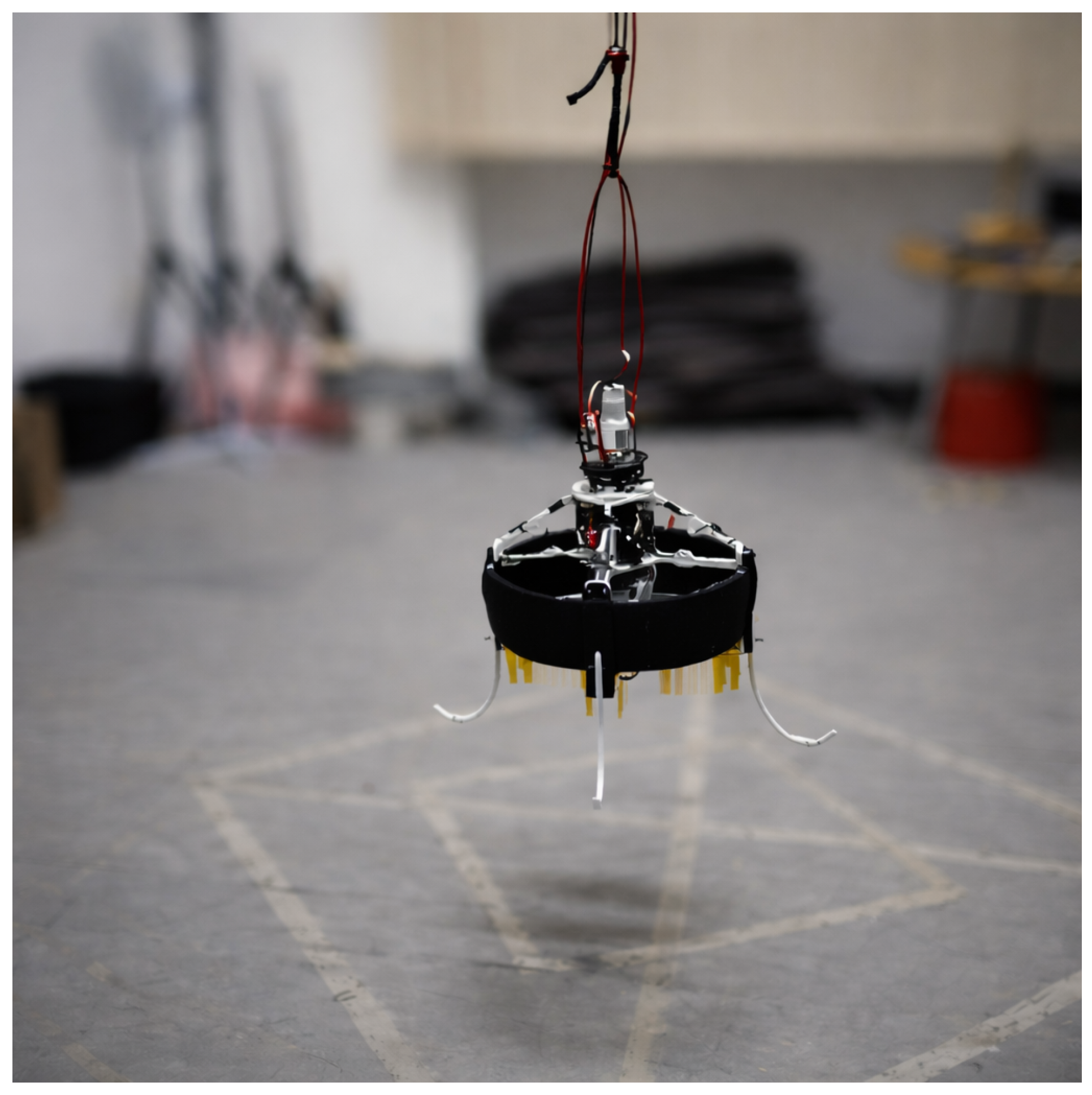
The main contributions of this work are to describe and detail in one place the full process of designing, building and flight-testing a low-cost ducted-fan UAV, to show that the proposed design can be exploited, replicated, and adapted to one’s own needs by any research laboratory, and to prove that critical components like the duct and the necessary custom-designed and optimized propellers can be realized successfully with affordable 3D printing technology. The UAV we designed at the University of Pisa was named Catafalcon and is shown in Figure 2. All Catafalcon mechanical and electronic components, including the duct and the propellers, are either readily available on the market or 3D-printable, making this design easily customizable to different needs.
The paper is structured as follows: Section 2 describes the entire design process and provides the theoretical basis as well as practical formulas and procedures that can be used for dimensioning the vehicle; Section 3 describes the dynamics of a generic ducted-fan vehicle and describes a basic control system that can be used as an inner control loop for stabilization and attitude regulation purposes; Section 4 shows the results of an experimental test campaign including propeller bench characterization and a flight test; and finally, Section 5 presents the conclusions and final remarks.

2. The Design Process

2.1. The Ducted-Fan UAV

A ducted-fan UAV is a vertical take-off and landing vehicle constituted by one or more propellers (the fans), fully enclosed in a duct; the duct increases the propellers’ efficiency thanks to a wise aerodynamic co-design of the propeller. In particular, the duct reduces tip vortex losses by limiting leakage flow through the small blade wall clearance, thereby decreasing induced drag and improving thrust [10]. The duct geometry also promotes pressure recovery and thrust augmentation, as the inlet lip enhances flow capture while the diffuser partially converts dynamic pressure into static pressure, allowing higher thrust for a given power input than an equivalent open propeller [11]. Moreover, the duct protects them from direct contact with external objects. Although ducted-fan UAVs have been proposed in various mechanical and actuation configurations [12,13,14], the simplest and most common configuration is a single vertical duct hosting two counter-rotating propellers that produce an accelerated air flow that is deflected sideways to generate actuation forces and moments. The vehicles depicted in Figure 1 are of this kind.
The components of a ducted-fan UAV that require the most design attention are the duct, the propellers, and the airflow deflectors. Propellers used in ducted-fans are specifically designed and are not usually commercially available: ducted-fan UAVs take advantage of the duct to increase the aerodynamic efficiency of the propeller and then to increase the total amount of thrust; thus, propellers must be quite different from those used in multicopters or helicopters, which instead are readily available on the market with various sizes and aerodynamic characteristics. In order to address this issue, this paper presents in full detail the design process that could be followed to obtain a specifically designed propeller and duct couple, and shows that the propeller blades can be 3D-printed and assembled in a fully working prototype propeller. In terms of the power source, while military ducted-fan UAVs are usually powered by a combustion engine to enhance autonomy and long-range flight, the current trend in civil ducted-fans is to move towards electric power, which results in more silent and lighter vehicles. Although most of the design process presented in this paper is independent of the type of propeller actuation system, Catafalcon UAV was designed to be electrically powered by Lithium–Polymer batteries, making powertrain design straightforward.
The deflectors are movable aerodynamic surfaces, like tiny wings, that, placed underneath the duct, are used to deflect the airflow sideways and to generate the necessary torques and control actions on the vehicle [15,16]. These are responsible for attitude stabilization and motion control of the vehicle, and thus must be actuated by high-bandwidth motors and connected to a closed-loop control system, also for manually piloted flight. Correct design of the deflectors and the motors driving them is fundamental since these are, excluding the propeller, the only vehicle actuators. Deflectors are vital for vehicle stability and must be protected from accidental contact with external objects when on the ground and in flight. Thus, all vehicles of this kind feature a set of long landing legs that also serve as a protection cage for the deflectors.
As in helicopters and multirotor propellers induce a counter-rotating torque on the structure of the aircraft; a simple strategy is usually adopted to compensate for such torque: the use of two counter-rotating propellers in order to have the two reaction torques cancel each other. Since cancellation cannot be perfect, the airflow deflectors are used to generate the necessary Yawing torque to counter-balance the residual propeller reaction torque.

2.2. Main Design Criteria and Procedure

The main idea behind Catafalcon is to design a vehicle suitable for research purposes to fill the lack of commercial vehicles of this kind. From this perspective, the design of each component is modular to allow engineers and scientists to easily replace components in order to test what they are researching. The structure of the duct, the propellers, and all body structural components are meant to be easily replaced also in the event of failures, so that the UAV is also easy to repair.
Modern additive manufacturing processes offer an easy way to design and realize experimental small-scale UAV prototypes [17,18]. 3D printing allows to design and directly build a prototype or a component that can be used soon after the design phase. Furthermore, structural components may be easily rebuilt and replaced in the event of failure or a fatal crash. All Catafalcon parts were custom-designed and 3D-printed, including the duct and the propellers.
Many plastic materials exist for the cheap and widely used fused filament deposition technology [19,20] with various mechanical properties. Polylactic Acid (PLA) is one of the most widely used for its cost and precision of details; thus, for this reason, PLA was used for all vehicle parts with the exception of electric motor supports. Since motors are expected to heat during flight, Acrylonitrile Butadiene Styrene (ABS) was chosen for motor supports for its greater heat resistance with respect to PLA.
Catafalcon produces vertical thrust using two coaxial, counter-rotating propellers that operate at the same angular speed. Such a configuration allows the cancellation of almost all gyroscopic effects and reaction torques induced by the motors and propellers; anyway, as described later, compensation is not perfect and a Yaw-damping controller must be employed. Moreover, the use of two propellers, as will be shown later, allows it to produce almost the double the thrust of a single propeller with a much smaller propeller (and vehicle) radius.
While the propellers’ thrust is the main thing responsible for maintaining the vehicle in flight by opposing the gravity force, the generation of additional forces and moments on the vehicle body is obtained by deflecting the airflow of the propellers themselves. Four airflow deflectors, mounted in a cross, are sufficient to generate independent Roll, Pitch and Yaw torques; they also generate forces on the vertical and horizontal plane. As will be described later, attitude stabilization of the vehicle is achieved using the torques only, while for positional control, it is achieved by tilting the vehicle; it is usually possible to neglect the deflector-generated forces since they represent only a small fraction of the total force acting on the vehicle. Such a solution, which has proven efficacy on other ducted-fan vehicles [21,22], was adopted for Catafalcon.
From the design standpoint, the duct’s aerodynamic shape was designed by making use of the procedure described in [23], while propellers were designed using blade element theory and were then realized with 3D printing.
The iterative procedure for conceptual design and component selection (motors, batteries, etc.) for a ducted-fan UAV is not very different from the design process of other VTOL platforms like, for instance, the widely used multi-rotors, and is described in many references [24,25,26]. The following briefly describes a procedure specialized for ducted-fan UAVs.
The main design steps could be summarized as follows. Start by defining the payload weight, and the desired flight time; then create an initial guess for vehicle dimensions (that directly influences the propeller size), and perform an initial motor and battery selection. Consider also the presence of the deflectors and their actuators. Make an estimate of the total vehicle structure weight, and derive the necessary thrust for hover (typically at a nominal working point between 50 and 65% of the maximum RPMs). The actual design phase continues by designing the propeller geometry, which is followed by a suitability check for the selected motor (the motor must be able to provide the necessary mechanical power). If passed, the duct is designed to obtain an estimate of expected efficiency. Now, an estimate of the total flight time can be obtained from the mechanical power needed to fly, the electric motor driver efficiency and the selected battery capacity. If flight time is satisfactory, the procedure ends; otherwise, if it is too low, for example, the propeller size can be enlarged and/or a larger capacity (and weight) battery selected. The procedure repeats until the designer is satisfied by the design.
This procedure is schematically depicted by Algorithm 1.
Algorithm 1 Ducted-Fan Aerial Vehicle Design Methodology
Require: 
Payload weight, hover duration, vehicle dimensions
  1:
Define an initial guess for battery, motor and propeller size
  2:
while estimated flight time < required hover duration do
  3:
      Estimate total structural weight including motor and battery weight
  4:
      Compute required propeller thrust at nominal operating point
  5:
      Design propeller geometry
  6:
      Check suitability of the selected motor, otherwise restart (goto 2) with new motor
  7:
      Design duct geometry
  8:
      Estimate flight time
  9:
      if Unsatisfactory, modify propeller size and/or battery (goto 2)
10:
end while

2.3. Structural Components Design

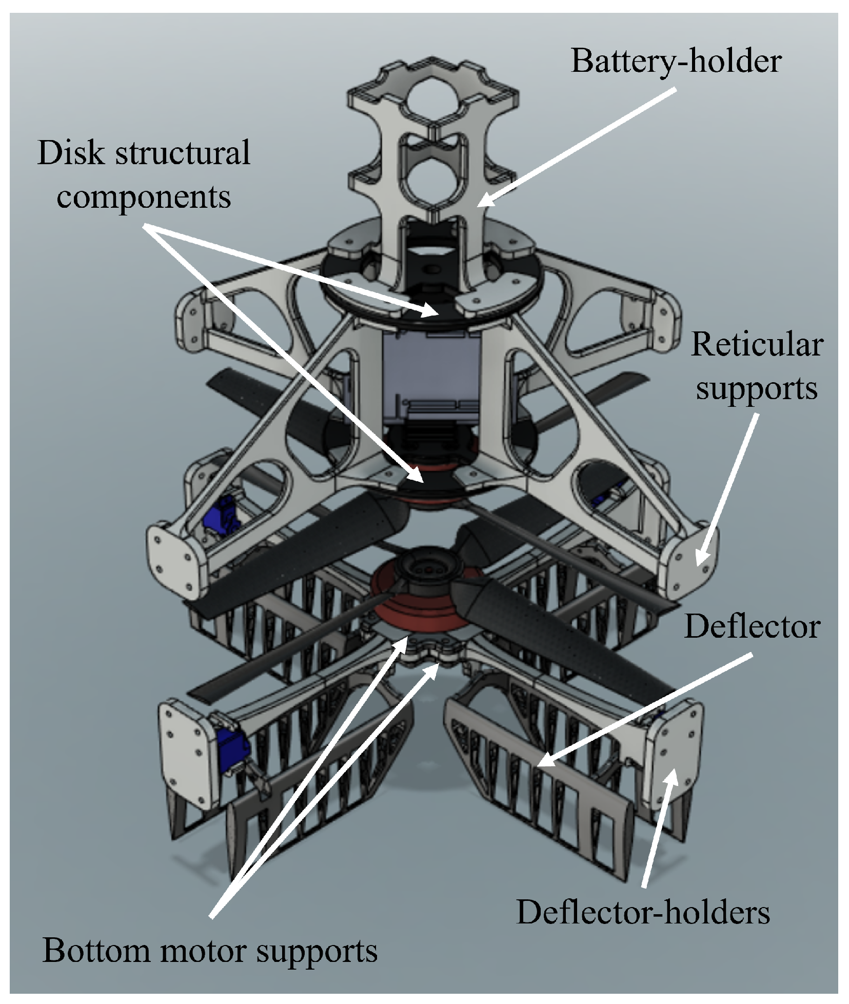
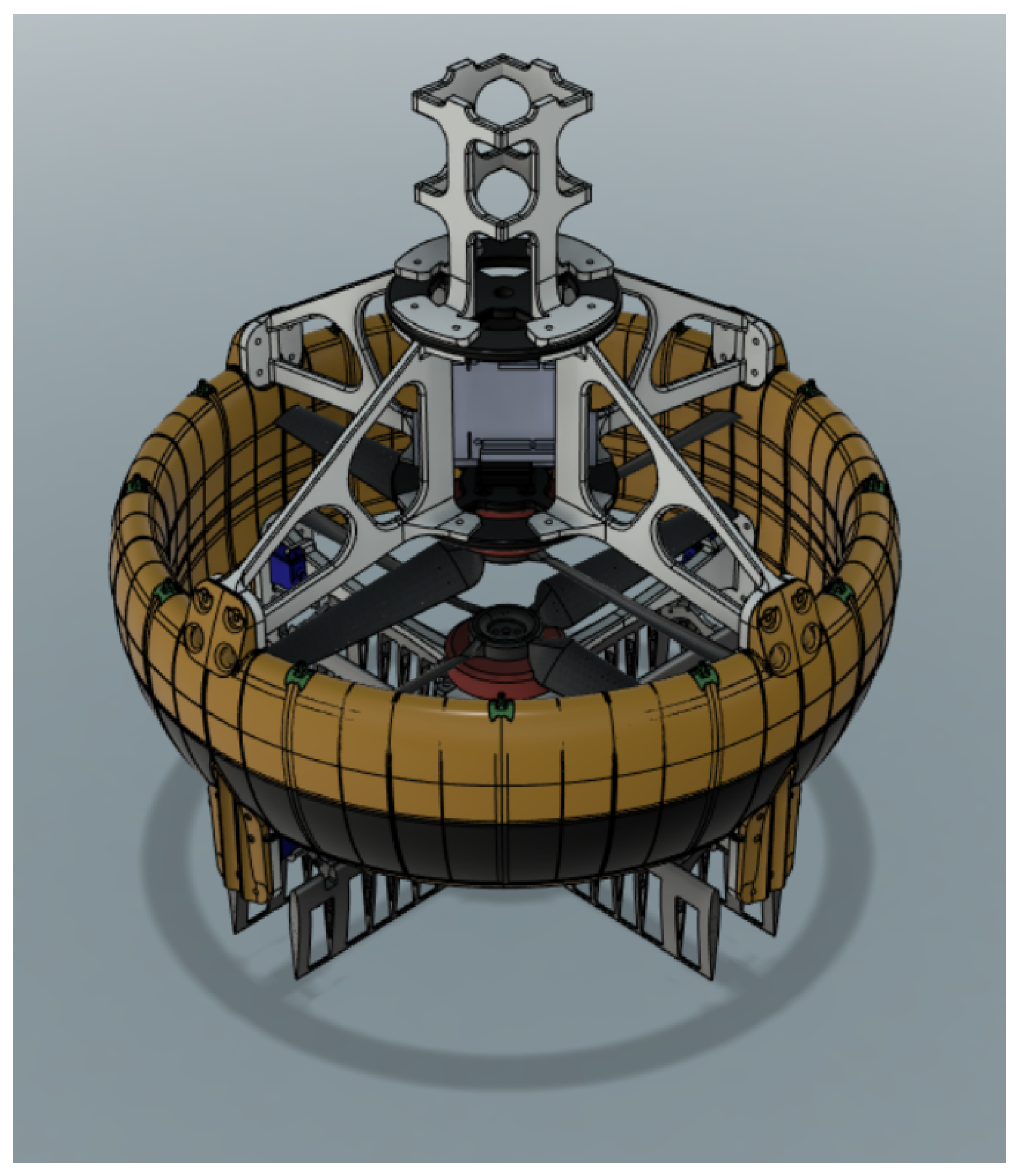
Catafalcon was designed with low weight and ease of assembly in mind. The main structural components of Catafalcon are the reticular supports, the deflector-holders, which are displayed in Figure 3, and the duct, displayed in Figure 4. All these components are designed as lightweight as possible without sacrificing structural resistance. Modularity allows changing each component if different configurations are needed. For example, if a different battery or different deflectors are intended to be used, only these parts must be redesigned and changed.
The upper body structure is composed of four reticular supports that are linked together through two disk-shaped structural components called disk structural components, displayed in Figure 3. The lower disk holds the Catafalcon upper motor and constitutes the base of the electronics compartment; the battery holder is connected to the upper disk. The lower motor support, displayed in Figure 3, comprises two identical components that connect together, like in a sandwich, and the four deflector-holders.
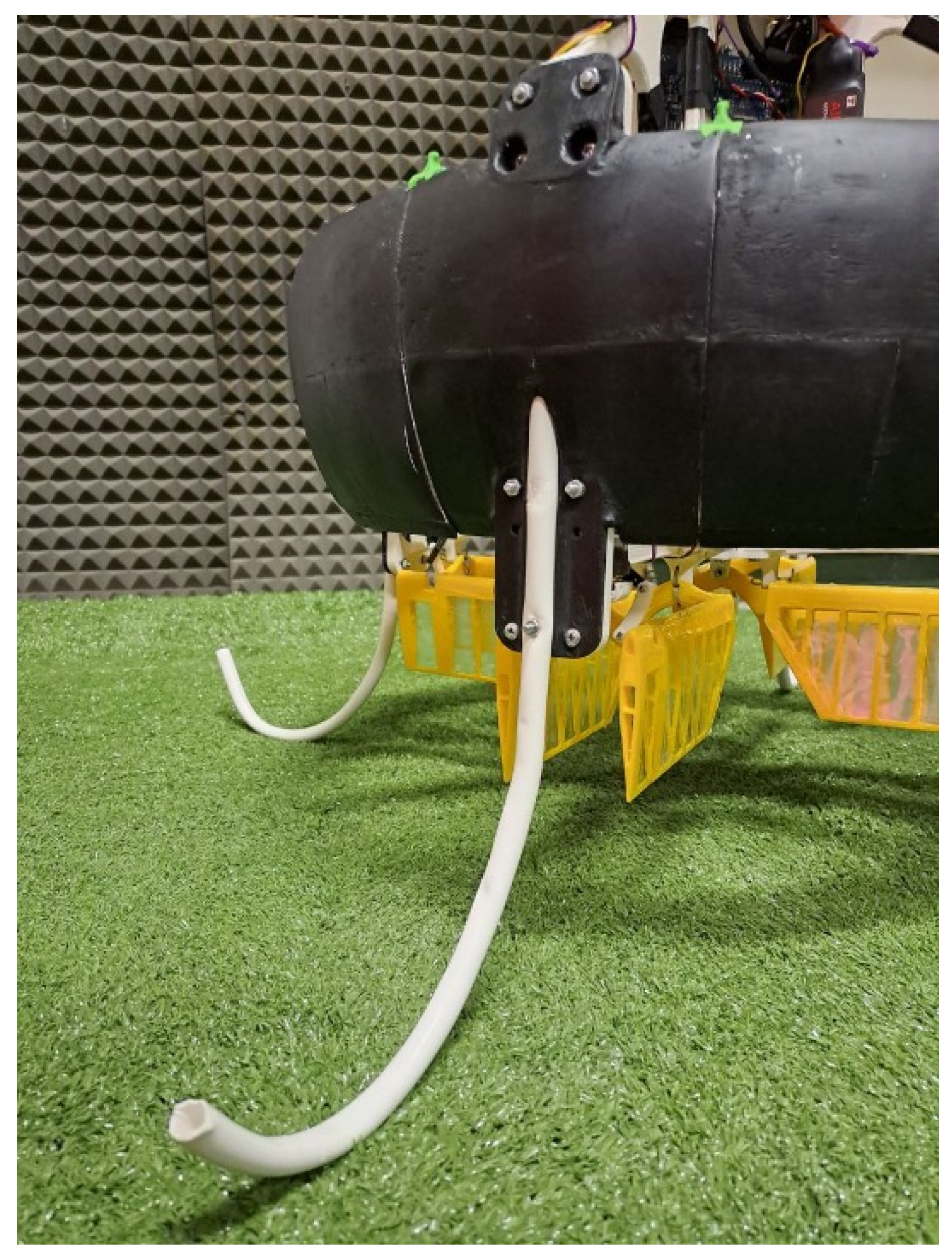
The upper and lower structures in Figure 3 are kept together stiffly by four columns embedded in the duct. Catafalcon’s legs (Figure 5) are also attached to the columns through semi-cylindrical housing. The four legs were made by thermally shaping four Polyvinyl Chloride (PVC) plastic tubes with a diameter of 7 mm. The four legs become the sacrificial parts of Catafalcon in case of a rough landing and can be cheaply replaced in case of breaking.

2.4. Propellers Design

Custom design of Catafalcon’s propellers is necessary due to the lack of availability on the market of propellers specifically designed for ducted-fans. Commercially available multirotor or airplane propellers are designed to rotate in free air and are tapered from root to tip to reduce vortex drag. In ducted-fan propellers, tapering is not necessary and would be improper, due to the presence of duct walls that prevent the formation of tip vortices: the narrow gap between the propeller’s tip and the duct walls increases efficiency and thus requires a specifically designed propeller [27,28].
As anticipated, Catafalcon has two contra-rotating propellers and the aerodynamics of the rotors can significantly influence its overall performance [29,30]. The flow field of a contra-rotating ducted fan is extremely complex, due to the mutual aerodynamic interference effects of the high-speed rotating propellers. The spacing adopted in this work follows established guidelines reported in the literature [31], while also accounting for packaging and space constraints in order to avoid an excessively large vehicle. Despite the complex aerodynamic field, in this work, the design of the propeller is based on Blade Element Theory (BET), following a similar procedure as in [32], in order to ease the calculations needed. BET consists of applying the theory used for wing profiles to a rotating blade by subdividing it into sections of infinitesimal thickness and integrating over them to obtain the total blade lift and resisting torque. BET takes into account the number of blades N B , the blade twist, and the aerodynamic characteristics of the profile along the blade. The axial flow speed, instead, is computed through Momentum Theory (MT), which gives a good approximation of larger-scale effects. These theories are best suited for larger aspect ratio blades and do not account for the unsteady flow in the duct; anyway, they provide a sufficiently accurate prediction of the propeller behavior in this application.
The blade design procedure aims to find the main blade parameters: airfoil, blade twist angle, chord distribution from hub to tip, and desired angle of attack that produce the desired thrust with the minimum drag at the desired operating condition. In this work, the design procedure starts using the hovering condition as the operating point. The duct section determines the propeller radius and the desired thrust is defined by the expected take-off weight of the vehicle. The desired propeller rotational speed is assumed known and becomes the input quantity used in the design. Once the propeller aerodynamic resisting torque is computed, it must be checked that the selected electric motor is capable of generating the corresponding torque. The common practice in small-scale vertical take-off and landing unmanned aerial vehicle motor selection is to use motors that provide the necessary hover thrust at around 50% of the maximum throttle. If the selected motor results are unsuitable, the procedure must be iterated.
In order to describe the propeller design procedure, let us first establish some basic approximate relationships. Naming U the effective air speed that invests the rotating element (namely a blade section of infinitesimal width at distance r from the propeller hub), it is possible to write:
U r = v 2 + Ω r 2
where v is the unknown axial flow speed, Ω is the propeller angular velocity and r is the blade radius at which the speed U is computed. Note that the radius r spans from the blade root R root to the blade tip R tip . Choosing hovering as the design point, the axial flow speed at the disc that is necessary to “generate” the needed thrust can be derived by MT. Considering the necessary thrust T equal to the ducted-fan estimated weight, the flow speed v can be computed as:
v = T ρ A
following a similar procedure as in [32] where the speed v is assumed constant along the radial direction, and A is the area of the disc covered by the propeller during its rotation, that is actually the area of the duct section.
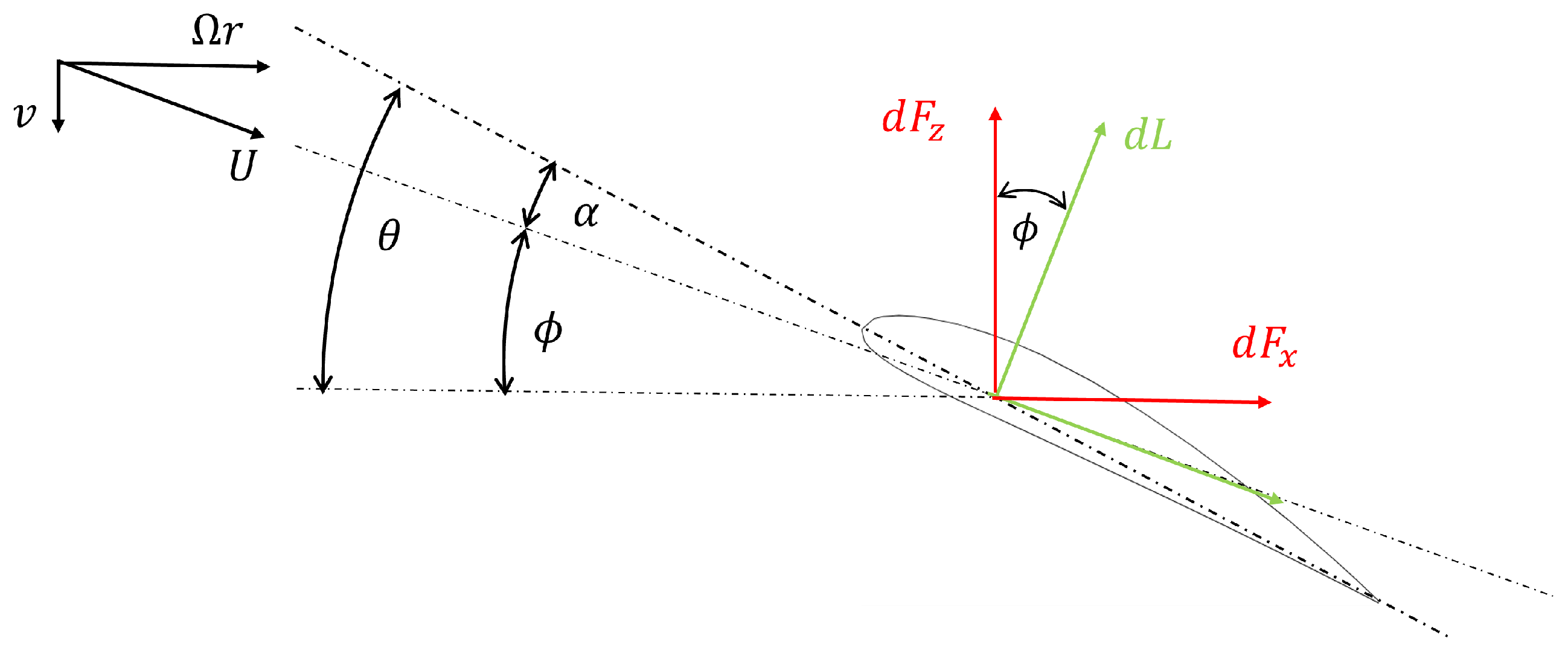
The angle ϕ between the airflow direction and a plane perpendicular to the rotation axis is called the geometric angle of the inflow and is obtained as:
ϕ r = arctan v Ω r
If the blade, at distance r from the hub, is twisted by an angle θ , then the angle of attack of the blade α , that is the angle between the airfoil chord and the velocity vector, becomes:
α = θ ϕ
The angle of attack is a fundamental quantity since all aerodynamic forces on the blade are functions of it. As anticipated, the design procedure requires the computation of an optimal distribution of the twist angle along the blade (i.e., from R root to R tip ). The effective twist angle distribution can be derived using Equations (3) and (4). Even if the variation of angle ϕ is nonlinear with respect to r, in order to have a simpler design, it is assumed to be linear and ranging from ϕ root to ϕ tip , which are computed as follows:
ϕ root = arctan v Ω R root
ϕ tip = arctan v Ω R tip
Then, the assumed linear flow angle distribution is:
ϕ r = k ϕ ( r R root ) + ϕ root R root < r < R tip
where k ϕ = ϕ tip ϕ root R tip R root is the linear distribution angular coefficient and it is k ϕ < 0 , being ϕ root > ϕ tip .
Figure 6 shows the forces and the main angles of a blade element section. The lift d L is perpendicular to the flow direction while the drag d D is parallel to the flow. The two aerodynamic forces are then projected onto the z and x axes to compute the infinitesimal contribution of each section to the thrust d T , and to the torque d Q .
The infinitesimal contributions of each section can be computed as follows [33]:
d L = 1 2 ρ U r 2 c r C L d r
d D = 1 2 ρ U r 2 c r C D d r
d T ( r ) = d F Z = d L cos ϕ d D sin ϕ
d Q ( r ) = d F X r = d L r sin ϕ + d D r cos ϕ
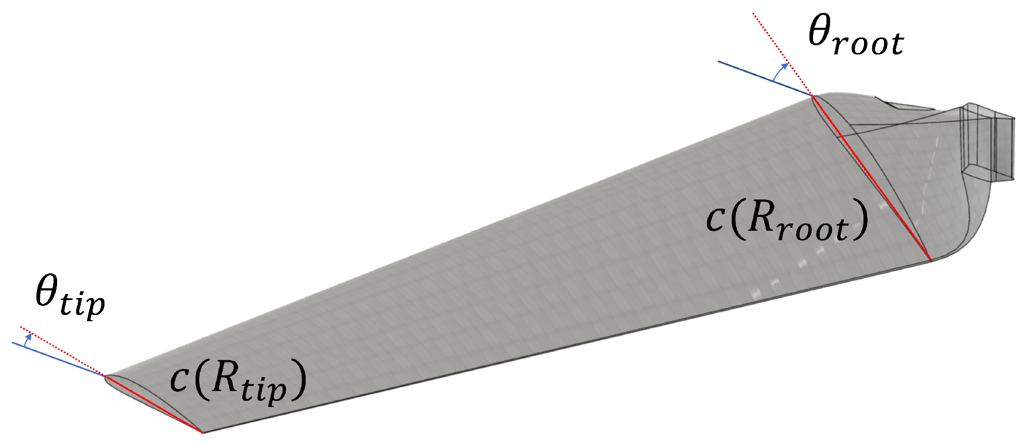
where C L and C D are the aerodynamic coefficients of the selected airfoil, which in turn are functions of α , and c r is the chord distribution which was selected to be linear along the blade with the following distribution:
c r = k c ( r R root ) + c root R root < r < R tip
with k c = c tip c root R tip R root < 0 .
Note that ϕ r o o t , k ϕ , c root , and k c constitute the blade parameters to be defined. Finally, the total thrust T of the propeller and its resisting torque Q are computed by integrating the infinitesimal contributions of all the blade sections along the radius R from the blade root to the blade tip:
T = N B R root R tip d T ( r )
Q = N B R root R tip d Q ( r )
where N b is the number of blades of the propeller. The value of thrust T in Equation (2) and in Equation (12) must match, and this is obtained iteratively by a proper selection of the geometric parameters α , c r and θ r .
In order to simplify the design, the two contra-rotating propellers are assumed to be coincident as if there was a single propeller with twice the number of blades, neglecting de facto any top and bottom propeller interaction [32]. Another simplifying, yet reasonable, assumption adopted during the design phase was to consider blade twisting and bending effects as negligible.
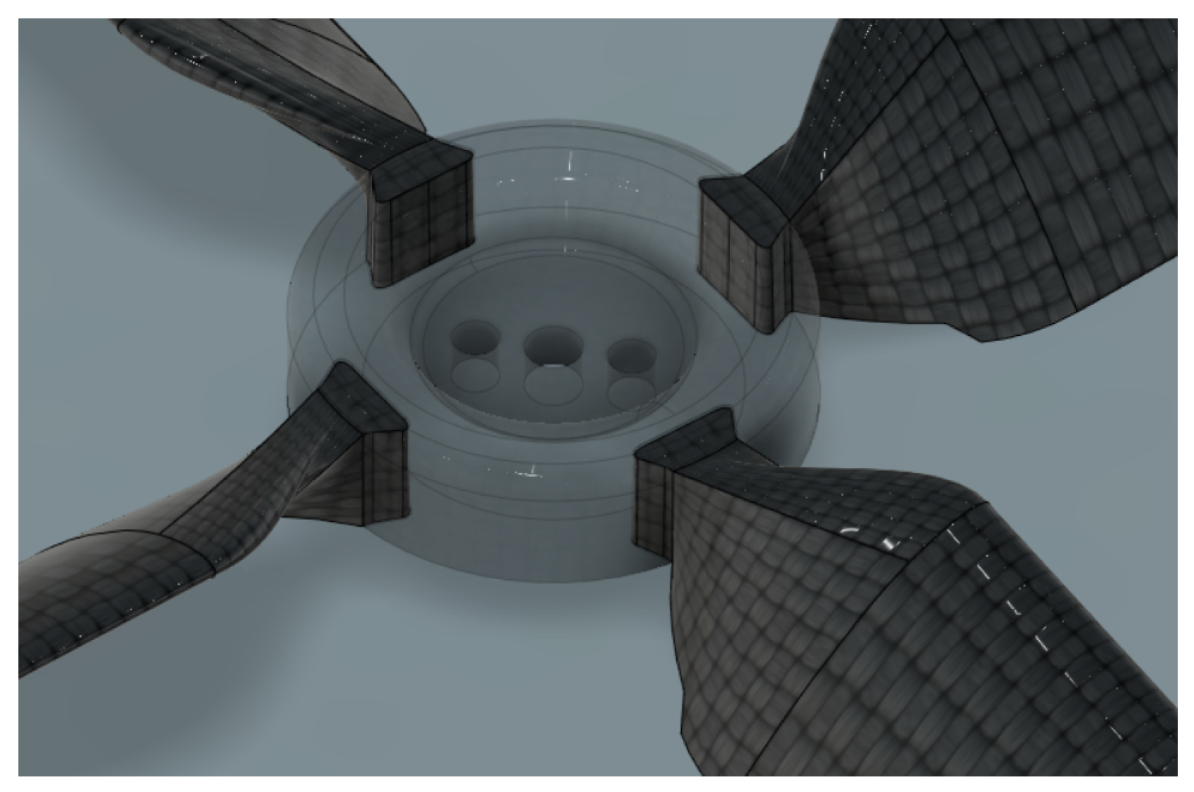
The design phase starts by selecting an airfoil and defining the angle of attack α such as to maximize the aerodynamic efficiency of the selected airfoil. The airfoil selected for this work is the NACA4412 due to its good performance even at low flow speeds. Note that once the airfoil is selected, all the coefficients considered in this work, and that are needed to compute the aerodynamic forces and moments, can be obtained directly by the standard NACA tables [34]. Assuming that the flow is at a low Reynolds number, the profile stall angle is at 9° while the maximum C l C d ratio is at α = 8.5 ° . This value for the angle of attack is the one where the profile has its maximum aerodynamic efficiency but is too close to the stall point, and a small variation to the flow angle or issues due to imperfect realization can lead the section to stall with suddenly a huge increase in drag and a decrease of thrust. The design angle of attack was then chosen to be 6.5°, which is close enough to the maximum efficiency point but far from the stall condition. The final propeller’s blade design is shown in Figure 7. The entire propeller is too large to be 3D-printed in one piece, thus each single blade was 3D-printed separately, and then assembled with a central hub. Since the connection between the blades and the hub has to sustain the stress generated by centrifugal forces and the stress due to generated thrust T, a dovetail connection, shown in Figure 8, was used. The dovetail joint was adopted as a simple and practical solution compatible with the modular, fully 3D-printed architecture, providing easy manufacturing, self-alignment during assembly, and sufficient robustness for experimental flight testing. In practice, the joints ensured reliable mechanical coupling and maintained structural integrity throughout the experimental campaign, with no detachment or significant degradation observed under normal operating conditions.
The thrust and torque computed through Equations (12) and (13) must be used to select the proper electrical motor to spin the propeller. The electrical motor has to be capable of working at the chosen operating condition, giving the right amount of torque at the desired angular speed. The expected motor temperature at the working point also has to be as low as possible to avoid any thermal problem involving the motor itself and the structure of Catafalcon that, being 3D-printed in plastic, might lose its mechanical properties if overheated.
Just as a reference, Catafalcon’s two propellers are mounted on two T-Motor Antigravity MN6007 KV320 outrunner brushless motors that are driven by two T-motor Air 40A Electronic Speed Controllers (ESCs), selected amongst those recommended by the motor producer.

2.5. Duct Design

The duct is one of the fundamental components of a ducted-fan vehicle and its design must pursue the goal of aerodynamic efficiency of the propulsion system. One possible approach is to follow the procedure described in [23], which uses a genetic algorithm to obtain the optimal duct airfoil section. In this method, starting from an initial shape, the algorithm generates a population of candidate designs represented by spline control points. Each candidate’s efficiency is evaluated using computational fluid dynamics (CFD), with a fitness value assigned based on performance. Pairs of elements are then combined with a probability proportional to their fitness, and this process continues over multiple iterations until the solution with the highest fitness is selected.
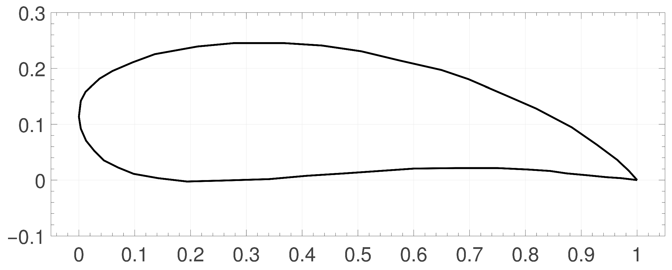
The author in [23] also provides recommendations and the rationale of his findings stemming from the detailed CFD analysis performed that can be simply followed to obtain a duct section that may also prove valid in different cases: in particular, Figure 9 shows a reconstruction of the optimal duct section for the coaxial case with the upper and lower propellers’ planes at ordinates 0.25 and 0.75, respectively. This duct section can be used as is provided the distance from the propeller tip at ordinate 0.25 is as small as possible to avoid tip vortexes; this ensures that flow maintains close to laminar in the expansion section in between the two propellers. While this approach is generally non-optimal compared to the results obtained through the genetic algorithm procedure, it greatly simplifies the procedure, especially for a research laboratory where CFD competences may not be present or a lower level of efficiency is acceptable, while providing a duct suitable for its use.
The duct section used in Cataflacon and taken from [23] is shown in Figure 9.
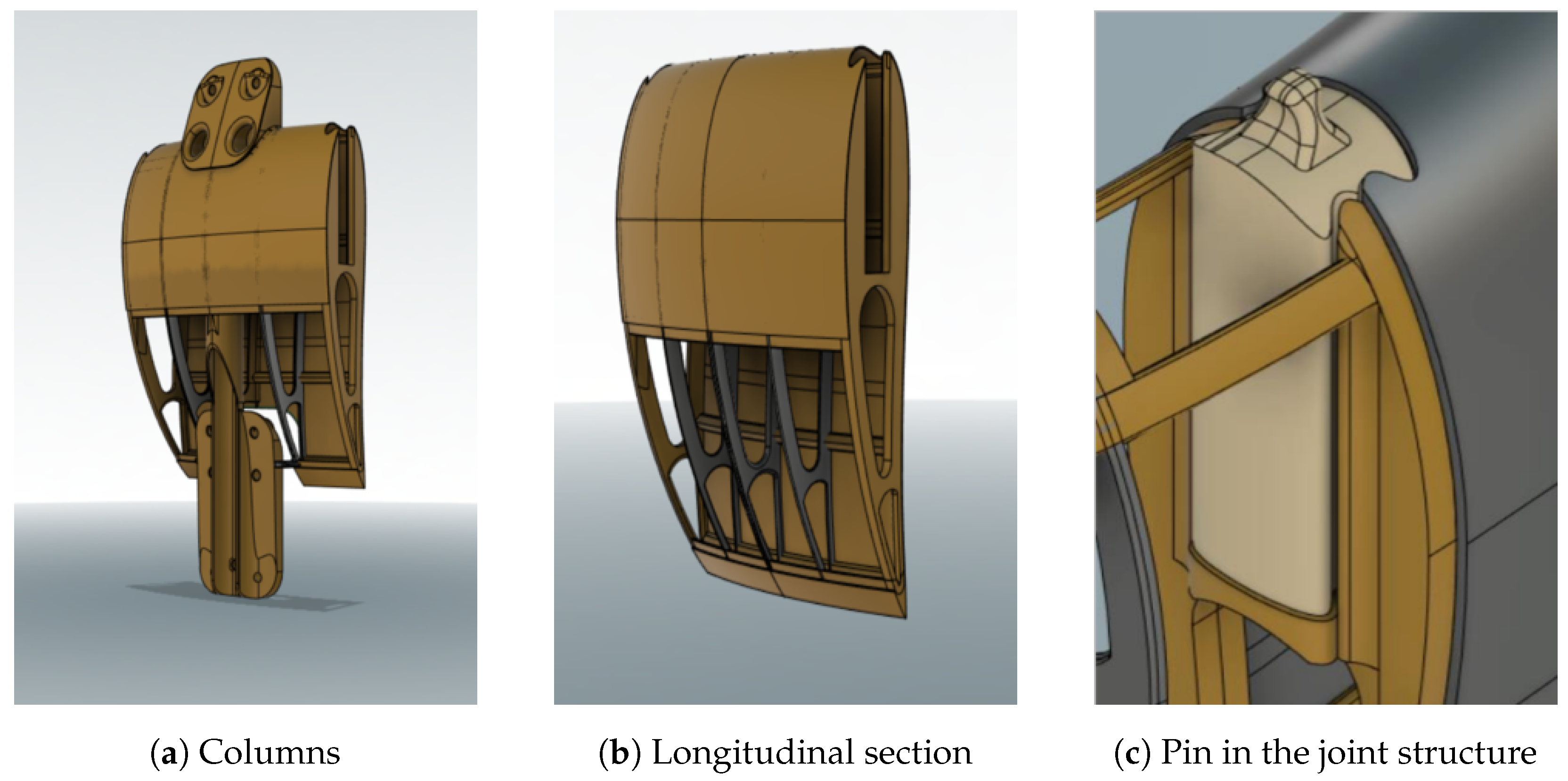
Once the optimized duct section is defined, it can be extruded on a circular path to obtain the 3D duct. Since this part is too large to fit the printing volume of most desktop 3D printers, the duct was split into smaller parts again with modularity and ease of replacement in mind. The duct structure realized through 3D printing in Polylactic Acid (PLA) material consists of three different component types:
  • Four main structural pieces, named columns, that connect the upper and lower part of the UAV: Figure 10a.
  • Eight duct longitudinal sections, simply named sections: Figure 10a.
  • Twelve dovetail pins that are used to connect adjacent columns and sections in joints, as in Figure 10c.
A modular duct structure is preferable to a single-piece duct due to two main reasons: easy-to-replace component design and 3D printer room constraints. Modularity, indeed, allows designing easy-to-replace components in case of a crash, or, if it is necessary, to test different architectures. Moreover, it leads to an easier printing procedure also due to a lack of room in the 3 D printer used. In order to obtain a lightweight duct, all its parts were designed as a thin surface layer connected by ribs, as in airplane wings. Additive manufacturing of such thin and lightweight structures requires the use, during 3D printing, of additional reinforcement structures, called support material, to be later removed. Thus, sections and columns were designed with an open slot on the lower half of the external airfoil. This slot allows removing the 3D printing support material easily. A PLA closing lid for the slot is printed separately and glued afterward. It should be noticed that printing such thin surfaces may represent a challenge if not correctly dealt with; in particular, the thickness of the duct surfaces must be set to an integer multiple of the diameter of the 3D printer nozzle. Failure to do so could result in higher surface roughness and imperfections. In our case, the surface thickness was set to 0.4 mm, the diameter of the printer nozzle adopted, to obtain a single layer of plastic. Duct components were 3D-printed and then treated with a filler, paper-sanded, and then spray-painted to remove any imperfections and obtain a surface as smooth as possible in order to reduce aerodynamic drag.
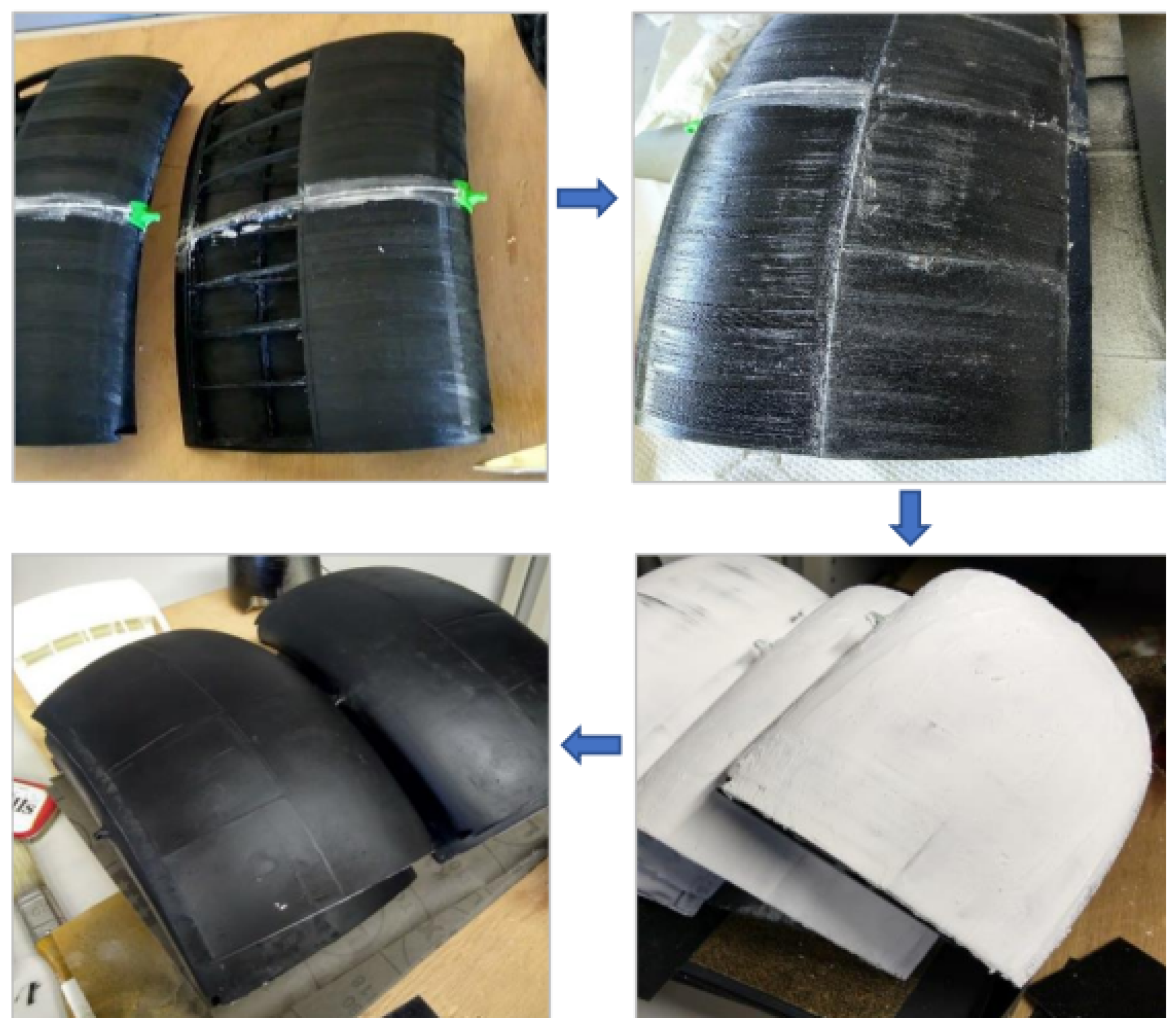
Figure 11 depicts the coating process on a section: following the arrows and starting from the top-left, two sections connected by a dovetail pin (green) as they are just after the printing procedure, the sections with the closing lids glued, the sections with filler applied, and the final result after sanding and black paint is applied.
Figure 4 shows the entire duct resulting from the assembly of 4 columns and 8 sections.

2.6. Deflector Design

Deflectors are the UAV control surfaces that generate control torques on the vehicle body, deflecting the flow induced by propellers and thus allowing the control loops to stabilize the vehicle dynamics and regulate its attitude. Each deflector consists of two wings with the NACA0012 symmetric profile. The choice of a symmetric profile is justified first because the deflector’s generated lift at a zero angle of incidence has to be zero, and because its action should be identical when deflected in one direction or the other. The deflectors have a rectangular planform, except for the tapered end, which prevents collisions between adjacent deflectors when they are deflected in intersecting directions. In order to design a very light deflector, its structure is almost empty and relies on seven ribs directly connected to the leading edge and the trailing edge of the profile with no spars, similarly to model airplanes’ wings. Each deflector is coated with a thin layer of transparent plastic to achieve a smooth and uniform surface. The necessary deflector size can be inferred from desired closed-loop attitude dynamics and vehicle inertia moments. Let us assume, for instance, the presence of a control system such that the closed-loop response from desired to actual vehicle attitude angle (Roll in this example) can be approximated by a second-order system like:
ϕ ( s ) ϕ d ( s ) = ω n 2 s 2 + 2 δ ω n s + ω n 2 = G ( s )
The angular acceleration ϕ ¨ ( t ) in response to a unit step has its maximum at the step time and is equal to ω n 2 (actually the modulus of the complex conjugate dominant poles, and the square of 3 dB bandwidth), as it can be easily proven by applying the initial value theorem to its Laplace transform: ϕ ¨ ( 0 ) = lim s s 1 s G ( s ) s 2 = ω n 2 . Clearly, the same stands for the Pitch angle.
Thus, calling α m a x the maximum desired angular excursion (Roll or Pitch) of the vehicle, the maximum value of angular acceleration during maneuvers can be estimated as η ¨ max = 2 ω n 2 α m a x , where the coefficient 2 takes into account the possibility of two subsequent step commands from α m a x to α m a x , or vice versa.
Maximum deflector angular excursion is limited by the stall condition of the NACA0012 profile, which in this flow condition is around 15 deg, and then the deflector’s maximum angular excursions are γ min = −15 deg and γ max = 15 deg. Considering this constraint, we can write:
I i η ¨ max = 2 L h
where I i is the inertia over one of the principal axes, h is the lever arm and L is the necessary lift to be produced by the deflectors. Since the deflector is nothing more than a wing invested by the airflow generated by the propeller, and the airflow velocity w below the propeller, according to the approximated model used, can be estimated to be double the axial flow velocity v (see Equation (2)), the lift L can be approximated by:
L = 1 2 ρ w 2 S c l γ γ max = 2 ρ v 2 S c l γ γ max
where c l γ is the airfoil linear lift curve slope and S is the deflector surface (relative to a single wing) to be determined.
The final deflector surface expression needed to generate the desired η ¨ max is then:
S = I i η ¨ max 4 m g c l γ γ max A
where A is the duct section, m is the vehicle mass and g is the acceleration of gravity. The deflector’s final design is shown in Figure 3.
It should be noted that, since Z-axis inertia is smaller than those for the X and Y axes, the Yaw moment is generated using 4 deflectors at the same time, and the desired closed-loop Yaw dynamics, not being involved primarily in stabilization, should have less stringent performance requirements, the deflector size designed for the desired Roll and Pitch performance surely fits the desired Yaw performance.
In order to actuate the deflectors, a servomotor capable of bringing the deflector angle γ to the value computed by the attitude control system is needed. For this project, tiny COTS servomotors, usually used to acrobatic model airplane control surfaces, were used.
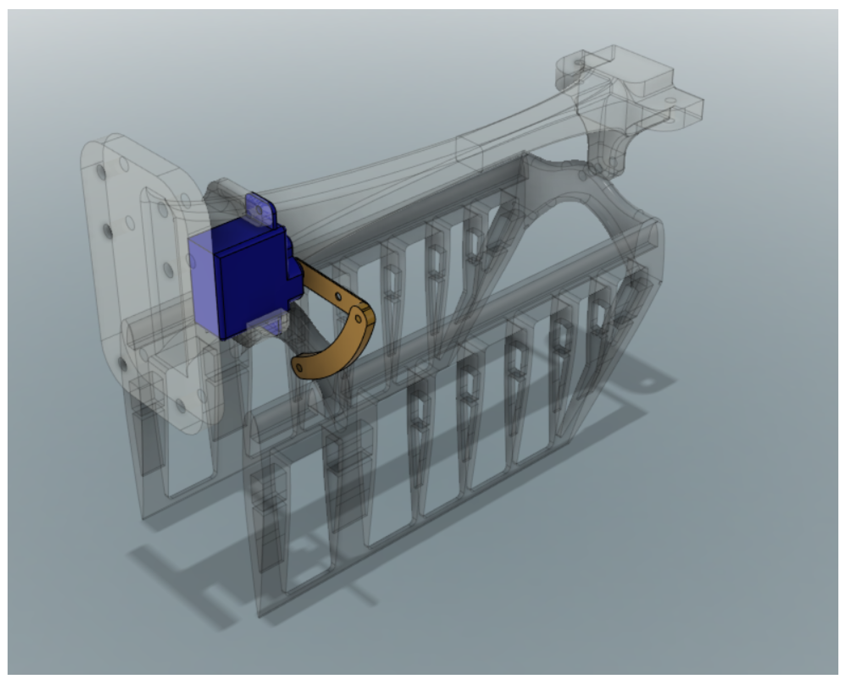
Figure 12 shows the deflector’s servomechanism and leverage. In the range of angular motion of the servomotor leverage, the relation between the servomotor torque and the torque applied to the deflector is approximately linear and can be written as: M deflector = k leverage M servo . The servo motor chosen must be capable to overcome the aerodynamic torque generated by the deflector’s wing profile. Just as a reference, the servo motors used in Catafalcon are Hitech HS-5055MG.
Table 1 contains the final design parameters used to build Catfalcon’s propeller blades, the deflectors, and the geometrical dimensions of the duct.

2.7. Onboard Sensors and Electronics

In order to stabilize the dynamics of such a vehicle, an onboard computer and a set of sensors are needed. These must include, as a minimum, a tri-axial accelerometer and a tri-axial gyroscope needed to estimate the vehicle attitude (namely its Roll and Pitch angles). A magnetometer and a GPS receiver are also needed if position and velocity control are desired. Additionally, a barometer or an altimeter may be needed if automatic height control is sought. Other sensors like cameras, lidar, etc., may be mounted on board for other functionalities like obstacle detection or vision-based navigation, but this discussion is outside the scope of this paper. Finally, a radio controller receiver is needed to receive pilot commands.
Most commercial autopilots might be used to implement these closed-loop functionalities and include the requested features. Catafalcon’s main control board, including all necessary sensors, is the ICARO autopilot [35]. ICARO is a versatile autopilot, for which the firmware for guidance, navigation, and control is written almost entirely in Matlab 2024b and Simulink code and has been used to control a wide range of aerial and terrestrial vehicles. The firmware is fully developed and maintained by the Autonomous System Laboratory at the University of Pisa. Onboard sensors include a 3-axis accelerometer, gyroscope, and magnetometer, a barometer for altitude measures, a GPS receiver and a WiFi telemetry module used to receive real-time data during the experiments that offers an interface for changing control gains. Inertial measurements are provided by an MPU6050 IMU, while altitude estimation relies on a BME280 barometric sensor. For indoor experiments, such as those presented in this work, GPS and magnetometer measurements are replaced by simulated signals derived from a Vicon motion capture system, which provides high-accuracy position and attitude data for state estimation and control. Wireless telemetry is implemented using an ESP8266 WiFi module.
Additional electronics include a Futaba T9CP radio receiver for pilot commands and a DC/DC converter to generate an adequate power supply for the servomotors (usually between 4.8 to 6 V).

3. Dynamics and Control

3.1. Vehicle Dynamics

In order to write the dynamic equations of a ducted-fan vehicle, we can start from those of a rigid body moving in tri-dimensional space [36]:
I ω ˙ IB B + ω IB B × I ω IB B = τ B
m v ˙ B + ω IB B × m v B = f B
where ω IB B = p , q , r is the angular speed between inertial (I) and body (B) frames, expressed in body frame, v B = v x , v y , v z is the linear speed expressed in body frame, and m and I are Catafalcon’s mass and inertia tensor. τ B = τ x , τ y τ z and f B = f x , f y , f z are the sum of all torques and forces applied to Catafalcon expressed in body frame, that can be written as:
f B = f p B + f g B + f aero B + f act B
τ B = τ gyro B + τ r B + τ aero B + τ act B
where f p B and τ gyro B are the sum of the propellers’ thrust forces and gyroscopic torques, τ r B are the motor reaction torques, f g B is the gravitational force, f aero B and τ aero B are the aerodynamic forces and torques, and finally, f act B and τ act B are the actuation forces and torques produced by Catafalcon’s deflectors.
Although an accurate vehicle dynamics model could be very complex, for the purpose of control system design, several simplifications can be made.
The total propellers’ force f p B is directed along the Z body axis and can be computed as the sum of the thrust generated by the two propellers. From an aerodynamic standpoint, the two propellers cannot generate the same thrust since the inflow velocity is different for the upper and lower propellers: the upper propeller accelerates the airflow so that the inflow at the lower propeller has a larger velocity. Nonetheless, the presence of the duct and the close distance of the two propellers mitigate this problem; thus, the two propellers, when in the duct and controlled to rotate at the same speed, should be able to produce almost double the thrust of a single propeller. This will be assessed experimentally in Section 4. Regarding instead the gyroscopic and reaction torques τ gyro B , the two propellers are controlled to rotate in opposite directions so that the torques generated by the two propellers should almost cancel each other. Active control, as discussed below, is nonetheless needed, since the residual reaction torque τ r B is present due to imperfections in constructions and also due to the different aerodynamics of the upper and lower propellers.
The aerodynamic forces and torques f aero B and τ aero B , mainly due to the interaction of the vehicle body and the duct with the air when flying, are quite difficult to model, but are small around the hover condition and become relevant only at higher translational speeds [37]. Thus, to the extent of this work, their presence can be neglected in the control system design and treated as external disturbances [4].
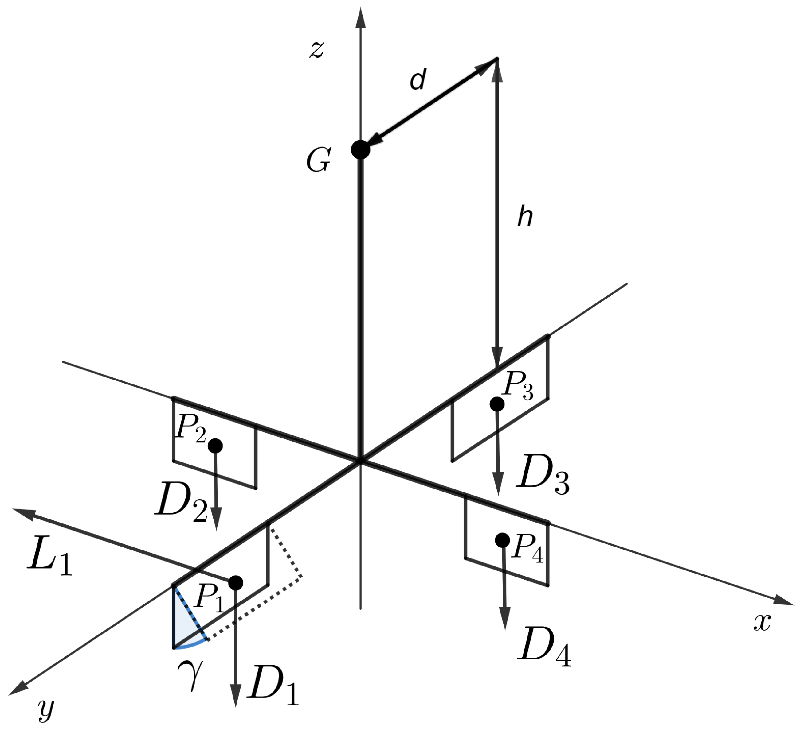
Figure 13 shows schematically how deflectors generate forces and torques on point G: Catafalcon’s center of mass. Each deflector P i is invested by the downstream air flow produced by the propellers; the speed of air w below the propeller, according to the approximate model used, is double the inflow velocity v. When deflected by angle γ i , the drag D i and lift L i forces are generated by each deflector; these can be written as:
L i = 1 2 ρ C l γ i S w 2
D i = 1 2 ρ C d γ i S w 2
C l γ i = c l γ γ i
C d γ i = c d γ γ i + c d 0
where c l γ , c d γ and c d 0 are lift and drag coefficients that can be obtained from the NACA tables and relate the angle of attack γ of the deflector, that corresponds to its deflection angle as set by the corresponding servomotor, to the actual generated forces. A pure moment is generated as well by the air flowing around the deflector, but its effect on the vehicle body is much smaller than that due to the lift forces, and, for this reason, it can be neglected. Although the profiles also produce drag forces, the C l C d ratio is quite high given the aerodynamic design of the profile, and therefore the drag force can also be neglected. Thus, the moments induced by the deflectors’ lift forces can be considered the main components of τ act B and the only relevant torques for the attitude control of Catafalcon.
The term f act B is composed instead of the sum of all aerodynamic forces produced by the deflectors, and it could be argued that these could be used for translational control of the vehicle. It should also be noticed that it is not possible to decouple the generation of forces from the generation of moments on the body, and, since moments produce tilting of the vehicle that reorients the thrust produced by the propellers in the direction of tilt, the amount of forces generated directly by the deflectors is orders of magnitude smaller than the portion of thrust directed horizontally due to tilting of the vehicle. Thus, the tilt angles (Roll or Pitch or both) become the actual control input for translational control.
Equations (21) and (23) can be combined giving the following result:
L i = κ c l γ γ i
where κ = 1 2 ρ S w 2 . The overall deflector torques acting on Catafalcon can therefore be written as:
τ act B = i = 4 4 G P i × L i n ^ i
where n ^ i is the unit vector that is orthogonal to the flow generated by the propellers, and to the hinge supporting the deflector. Distance vectors from point G to point P i have the following components:
G P 1 = 0 d h G P 2 = d 0 h G P 3 = 0 d h G P 4 = d 0 h
Torques for each deflector as function of γ i are then:
τ 1 = 0 h L 1 d L 1 τ 2 = h L 2 0 d L 2 τ 3 = 0 h L 3 d L 3 τ 4 = h L 4 0 d L 4
Thus, the total torque vector in Equation (26) can be rewritten as:
τ act B = κ c l γ h γ 2 γ 4 κ c l γ h γ 3 γ 1 κ c l γ d γ 1 + γ 2 + γ 3 + γ 4
where it is possible to see which deflector must be used to generate the control torques needed to implement attitude stabilization. Just as an example, to achieve a Roll torque, it is necessary to use deflectors D 2 and D 4 : setting γ 2 = γ 4 (with γ 1 = γ 3 = 0 ) produces a Roll torque and no Pitch and Yaw torques. Similarly, setting γ 1 = γ 3 (and γ 2 = γ 4 = 0 ) produces a Pitch toque and no Roll and Yaw torques. Finally, a pure Yaw torque can be achieved by setting γ 1 = γ 2 = γ 3 = γ 4 .
In the most general case, in which contemporaneous Roll, Pitch, and Yaw torques may be requested by the controllers, the control allocation problem can be formulated as finding the four γ i that produce the desired Roll, Pitch and Yaw torques ( τ x , τ y and τ z ) according to:
τ act B = τ x τ y τ z = κ c l γ 0 h 0 h h 0 h 0 d d d d γ 1 γ 2 γ 3 γ 4
Since Equation (28) can be rewritten as:
τ act B = κ c l γ B γ
where γ = γ 1 , γ 2 , γ 3 , γ 4 T is the vector of the deflector angles, the control allocation problem can be solved as:
γ = 1 κ c l γ B + τ act B

3.2. Vehicle Control

The control system of such a vehicle, as for most aerial vehicles in fact, is usually composed of several control loops nested one within the other: an angular velocity controller that regulates the vehicle’s angular velocity to desired values and stabilizes its highly unstable dynamics, an attitude controller that regulates the attitude (Roll, Pitch and, for some applications, Yaw) angles to desired values by means of generating appropriate desired angular velocities, and other outer loop controllers that regulate kinematic variables (linear velocity and position) with respect to some reference frames and some control goal, generating reference attitude angles to achieve the desired displacement. The rationale and structure of outer loop controllers for ducted-fan vehicles are very similar to those of all other vertical take-off and landing vehicles (helicopters, multi-rotors, etc.) that need to tilt to orient the lift force generated by the propellers toward the desired direction of motion [7,38,39], and its discussion is outside the scope of this paper; for this reason, the minimal set of control loops that are necessary to perform safe and almost effortless remotely piloted test flights was considered.
Although the dynamics of a ducted-fan aerial vehicle is more similar to that of a thrust vectoring rocket than that of other apparently similar vehicles [4], it is possible, thanks to the abstraction represented by Equation (30), to design its control system as if the system input was the vector of the torques applied to it. Thus, the controllers described below are designed using the components of the vector of body torques as the output.
In terms of control goals for allowing close-to-manual piloted flight, there are two main options: Rate Control (RC) or Attitude Control (AC). In RC mode, the pilot deflects the control sticks on the radio controller and commands rates of attitude angles: deflection of the stick is mapped (usually linearly, but often nonlinear characteristics are used to allow for faster maneuvers) into desired rates of Roll, Pitch and Yaw angles. RC mode is usually employed when rapid and/or aerobatic maneuvers are sought or when precise pointing is needed.
In AC mode, the pilot is given control of Roll and Pitch angles directly while, for very practical reasons, control of the Yaw axis remains in terms of rotation rate: deflection of the stick is mapped into desired values of the Roll and Pitch angles and, again, desired Yaw rate. This mode produces softer maneuvers and makes the vehicle much easier to be flown.
For the purposes of testing Catafalcon in flight in the tight space of the flight control room at the University of Pisa, controllers for AC mode only were implemented. Nonetheless, the considerations below remain valid also for implementing RC mode controllers.
When slow and stable maneuvers are sought, and also when hovering, Roll and Pitch angles remain small for most of the time; this allows us to consider the time derivatives of attitude angles equal to the angular velocity around the three body axis:
ϕ ˙ θ ˙ ψ ˙ p q r
Furthermore, assuming a symmetric body (that implies I x = I y = J ), as Catafalcon approximately is, Equation (17), written explicitly for the three body axis, reduces to:
p ˙ = τ x I x + I z I y I x q r
q ˙ = τ y I y + I x I z I y p r
r ˙ = τ z I z
With these assumptions, the dynamics of the three attitude degrees of freedom become almost completely decoupled. This allows us to design three separate controllers for regulating Roll and Pitch angles and Yaw rate.
It should be noticed first, that although Catafalcon has two identical counter-rotating propellers, and so gyroscopic effects can be considered negligible and reaction torques cancel each other (that is, τ gyro B 0 and τ r B 0 ), in reality, the cancellation of the gyroscopic and reaction torques is not perfect and therefore the vehicle has a natural tendency to rotate around the vertical axis; this tendency can be countered using the torque τ z produced using the deflectors, to regulate the Yaw rate r to 0.
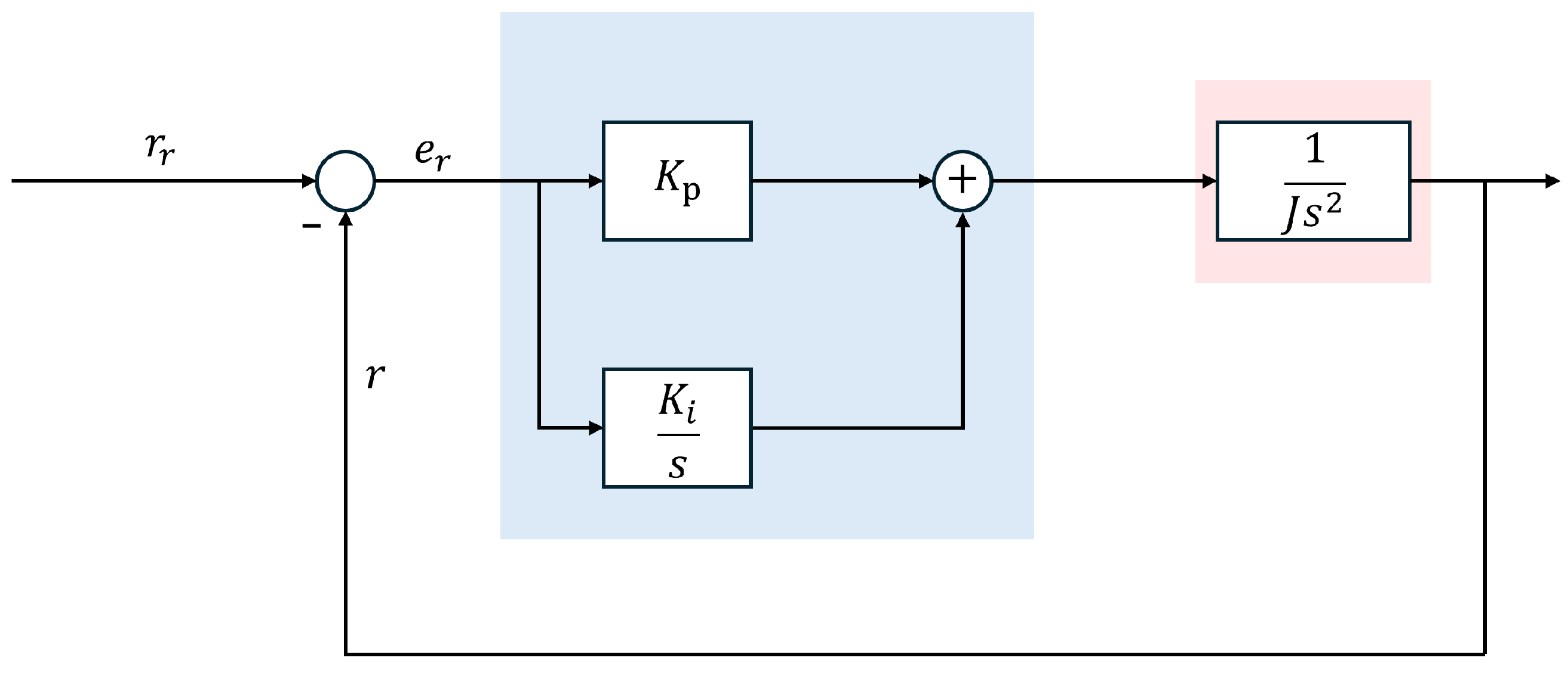
Given the very simple Yaw rate dynamics, a proportional-integral ( P I ) controller can be used. This allows reference tracking with zero error and also disturbance rejection.
The Yaw rate controller is described by Equation (35):
u rot = k p , r e r + k i , r s e r
where e r = r ref r is the Yaw rate error, and k p , r and k i , r are the proportional and integral gains. Figure 14 shows the Yaw rate control loop structure where u rot s = τ act , z s , which is the torque generated by deflectors over the z body axes.
Using Equations (34) and (35), the closed-loop Yaw rate dynamics can be written as:
r s = k p , r s + k i , r I z s 2 + k p , r s + k i , r r ref s
and appropriate choice of the controller’s gains yields the desired well-damped closed-loop response.
The main purpose of this control loop is to compensate for reaction torques that are generated by the propellers’ rotation if their angular speeds are not perfectly equal, and, consequently, to keep the vehicle orientation (around the vertical axis) constant. The signal r ref is generated by the pilot using one of the sticks of the radio controller.
It should be noticed that, given the presence of the Yaw rate controller that keeps r = 0 , Equations (32) and (33) can be simplified further as p ˙ = τ x I x and q ˙ = τ y I y .
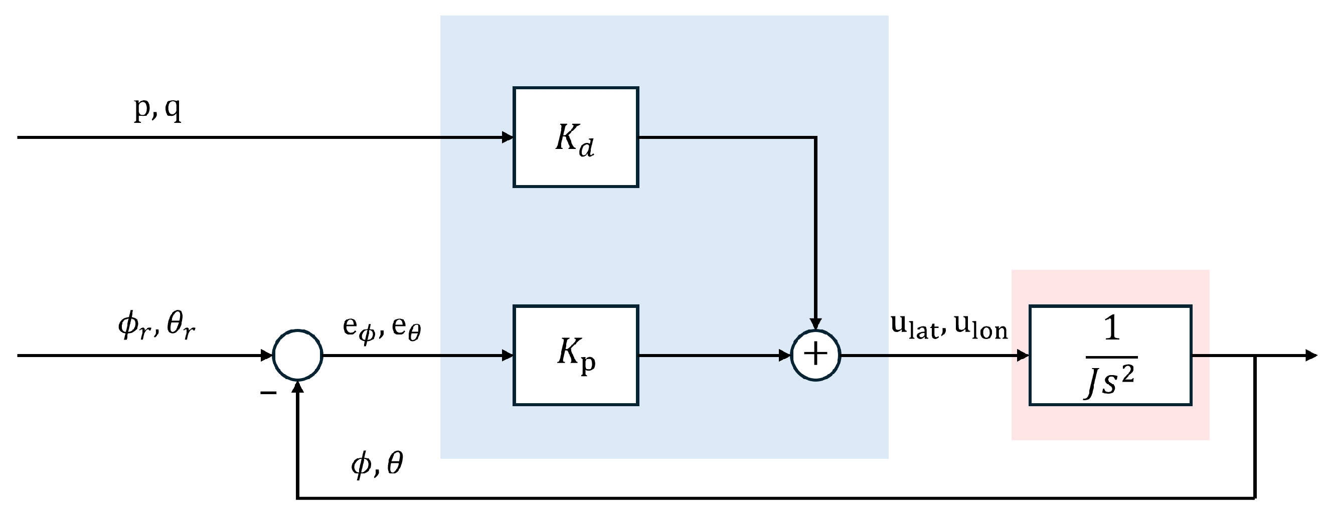
Thus, Roll and Pitch angle dynamics can be considered as that of two double integrators and stabilized using proportional-derivative ( P D ) controllers. Since the integral of angular velocity (i.e., the angle) is used directly as feedback, an integral action in the controller is not strictly necessary since rejection of disturbance torques on angle rates is achieved with pure proportional control. The derivative action is nonetheless necessary to dump the unstable oscillatory modes that would result from pure proportional control. A moderate steady state angle error may be present when subject to torque disturbances, but this is usually and easily compensated for by the pilot or by outer loop controllers.
Given vehicle symmetry, the Roll and Pitch controllers use the same proportional K p and derivative K d gains, and the derivatives of the current Roll and Pitch angles are assumed equal to angular speed as in Equation (31).
Thus, the Roll and Pitch controllers are:
u lat s = k p e ϕ s + k d p s ,
u lon s = k p e θ s + k d q s ,
where e ϕ = ϕ ref ϕ   e θ = θ ref θ   k p and k d are the proportional and derivative gains and u lat s = τ act , x s , u lon s = τ act , y s are torques generated by deflectors over the x and y body axes, respectively. The values of ϕ ref and θ ref are generated by the pilot using one of the sticks of the radio controller.
Figure 15 shows the Roll and Pitch PD controllers’ structure.
With these controllers, the closed-loop attitude dynamics become:
θ s = k p J s 2 k d s + k p θ ref s
ϕ s = k p J s 2 k d s + k p ϕ ref s
where it is easy to see that any desired well-behaved response can be achieved by appropriate selection of the control gains.
Controller tuning was performed using a trial and error process during test flights. Final tuning gains are shown in Table 2.
Vertical velocity and position control, in the so-called AC mode, are usually performed manually by the pilot, since this allows a broader range of testing possibilities even if it makes flying more tiring and difficult. This mode was then also used for Catafalcon: one of the sticks of the radio controller was connected directly to the propeller controllers allowing the pilot to finely regulate vertical thrust for take-off, landing and altitude holding/changing, but also to easily perform “shutdown” maneuvers if needed.
Although the employed ICARO autopilot would be capable of implementing classical outer loop control functions like altitude control, velocity and position control, etc., and also advanced control functions like vision-/lidar-based navigation and obstacle avoidance, as anticipated, these are outside of the scope of this paper and will not be discussed here.

4. Experimental Results

This section briefly reports the results of the test campaigns that were conducted in order to assess and validate the main design issues: the actual propeller thrust capability, the deflector’s effectiveness, and the “handling qualities” of Catafalcon.

4.1. Bench Tests: Propellers

In order to preliminarily assess the capability of the 3D-printed propellers to generate the expected amount of thrust, bench tests were conducted using a straight bar strain-gauge load cell with a maximum load capacity of 5 kg, interfaced through an HX711 ADC module, to measure the produced thrust at various rotational speeds.
With the entire design being modular, and since the propeller hub was designed to host a variable number of blades, the designed propeller was tested in two configurations: two-blade and four-blade. The thrust produced by the selected motor was measured using a load cell over the full throttle range from 0 % to 100 % .
The measurements were repeated across multiple experimental runs. In particular, for both the two-blade and the four-blade propeller configurations, each throttle level was maintained for an extended period, allowing repeated measurements to be collected within the same experiment.
For mounting and measurement issues, it was not possible to test the two propellers in their final positions inside the duct; thus, a single propeller was tested in free air. Since the propeller was designed, especially regarding the wing tip, specifically to be used in the duct, the total thrust developed is expected to be lower than the actual capability when in the duct.
Additionally, since only one propeller at a time could be tested, it was not possible to evaluate the losses that are expected with counter-rotating propellers positioned one above the other.
Furthermore, as will be shown below, the overall achieved thrust during flight tests proved to be very close to the design point.
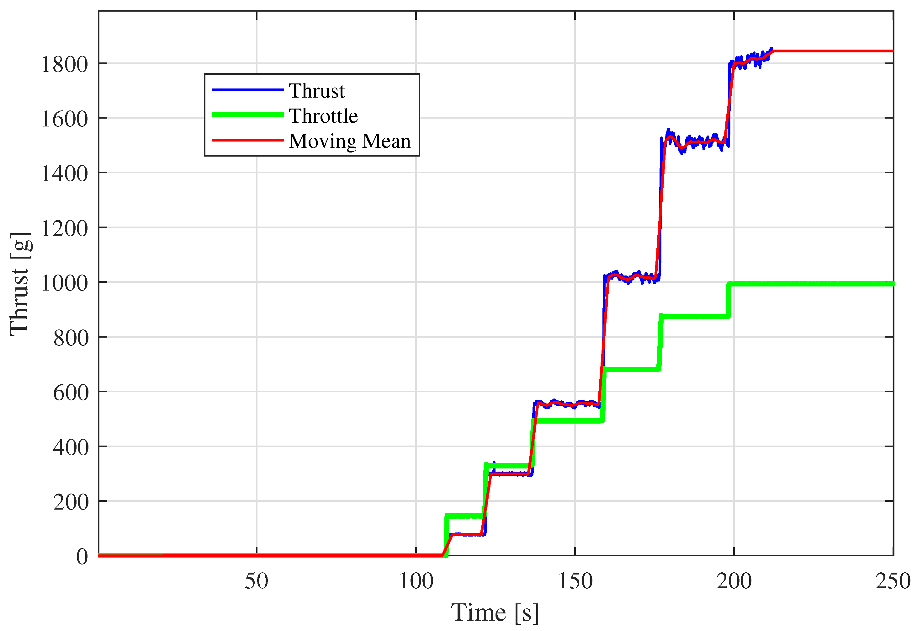
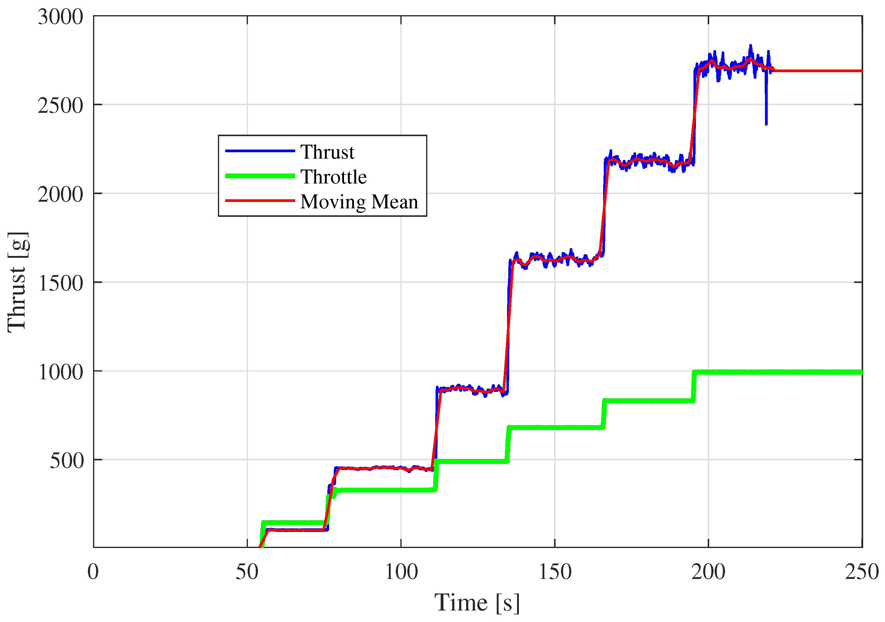
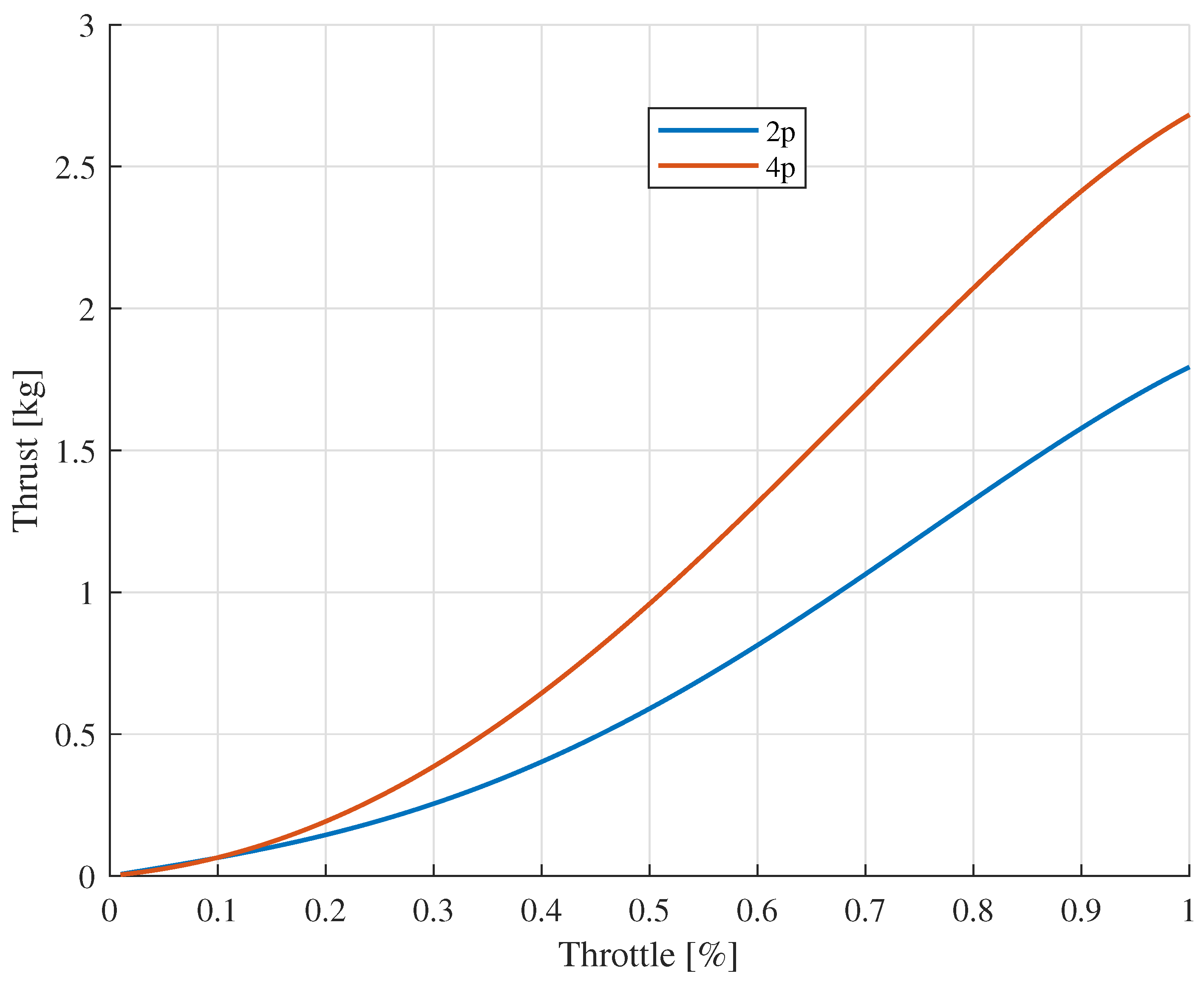
Figure 16 shows a sample result obtained with the two-blade propeller. The green line represents the per mil of throttle, and the blue line is the actual thrust measurement. Since the experimental setup was subject to a significant amount of vibration, especially at high rotational speeds, the measured thrust signal was filtered using a moving average filter that resulted in the red line in the figure. A sample test result with the four-blade propeller is shown in Figure 17. Finally, Figure 18 shows continuous thrust curves obtained, interpolating with a third-order polynomial, a large dataset of experimental data.
Table 3 summarizes the thrust achieved at the maximum throttle and at the design point, which is at 50 % of the throttle. As explained above, these values are not perfectly representative of the actual thrust that will be developed inside the duct, since the tests were performed in free air. With respect to this, we expect an increase in thrust, although its amount is not easy to predict numerically.
The Catafalcon total thrust will be produced by two contra-rotating propellers, one above the other. Experimental evidence and literature indicate that the lower propeller should produce around 20 % to 25 % less thrust than the one above. Thus, using two propellers should increase the thrust by a factor of 1.75 1.80 . This is what happens, for instance, in multicopter configurations that employ counter-rotating coaxial propellers on each arm.
These results would indicate that, even with two four-blade propellers, the total thrust needed to lift and hover Catafalcon, which weighs 3.1 kg including the battery, should be achievable at values close to 75 % of throttle, much higher than the desired 50 % .
Luckily, as predicted from theory, the presence of the duct was fundamental for the propulsion efficiency: during flight tests, we verified that Catafalcon can take off and hover, using two four-blade propellers, at a throttle of around 60 % , which means that the target of 50 % throttle take off is, anyway, slightly missed. By looking at Figure 18, it is possible to read that a single four-blade propeller produces a thrust of about 1.4 kg in free air at 60 % of throttle. Thus, due to the presence of the duct, the free thrust is incremented by a factor of 2.1 with respect to a single four-blade propeller. The increase is evaluated with respect to a single propeller, as the thrust produced by two counter-rotating propellers without the duct, for practical reasons connected to building an appropriate experimental setup, was not directly measured. Such a factor is in accordance with the literature [40].
Missing the design point may have several explanations; above all is the fact that the propeller blades, in order to make them stronger to centrifugal stress, were 3D-printed horizontally; this resulted in blades with pronounced surface roughness, irregularities and discontinuities of thickness. It is well known that aerodynamic surfaces must be as smooth as possible to avoid vortexes and drag increase, and this is particularly true for wings and propeller blades, and Catafalcon 3D-printed propellers are still much rougher than those produced industrially with plastic injection molds. This indicates that, although this project and Catafalcon itself proved the possibility to build a fully 3D-printed ducted-fan vehicle, the process of blade 3D printing is key and clearly has margins for improvement, including the possibility of better post-processing, paper sanding, and polishing of the blade surfaces.
Nonetheless, given that no post-processing was performed on the propellers, combined with all the uncertainty factors including the 3D printing process, the experimental results obtained can be considered a full success.

4.2. Flight Tests: Attitude Control System

Several flight tests were conducted in order to tune the controller gains. Initial values of gains were obtained from model-based design using approximate models in Equations (39), (40) and (36). Then, given the relative safety of handling the vehicle with bare hands (which would have been more difficult and hazardous with a conventional multirotor, even with propeller guards), initial tests were performed by holding the vehicle from the battery compartment up to the take-off point. The control gains were progressively adjusted until sufficient stiffness to manually induced disturbances was achieved and the response to pilot commands became fast and stable. Once adequate stiffness and responsiveness were reached, actual flight tests began. Although it might be considered naive and rough, this approach is simple to perform and quite safe for both the pilot and especially the vehicle, since the chance of a fatal crash during the first flights becomes very unlikely. It requires, though, a little trial and error to acquire the necessary experience to evaluate the quality of regulation without resorting to data analysis.
Once this initial phase was concluded, actual fine-tuning of gains was performed in-flight, starting, however, from already stable closed dynamics, making flight testing much more comfortable and risk-free.
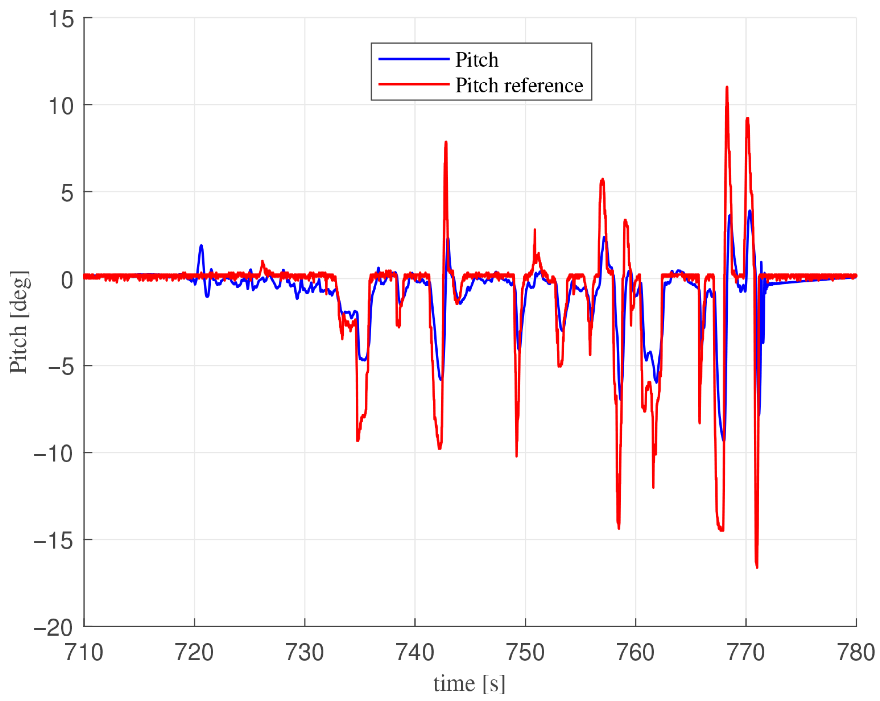
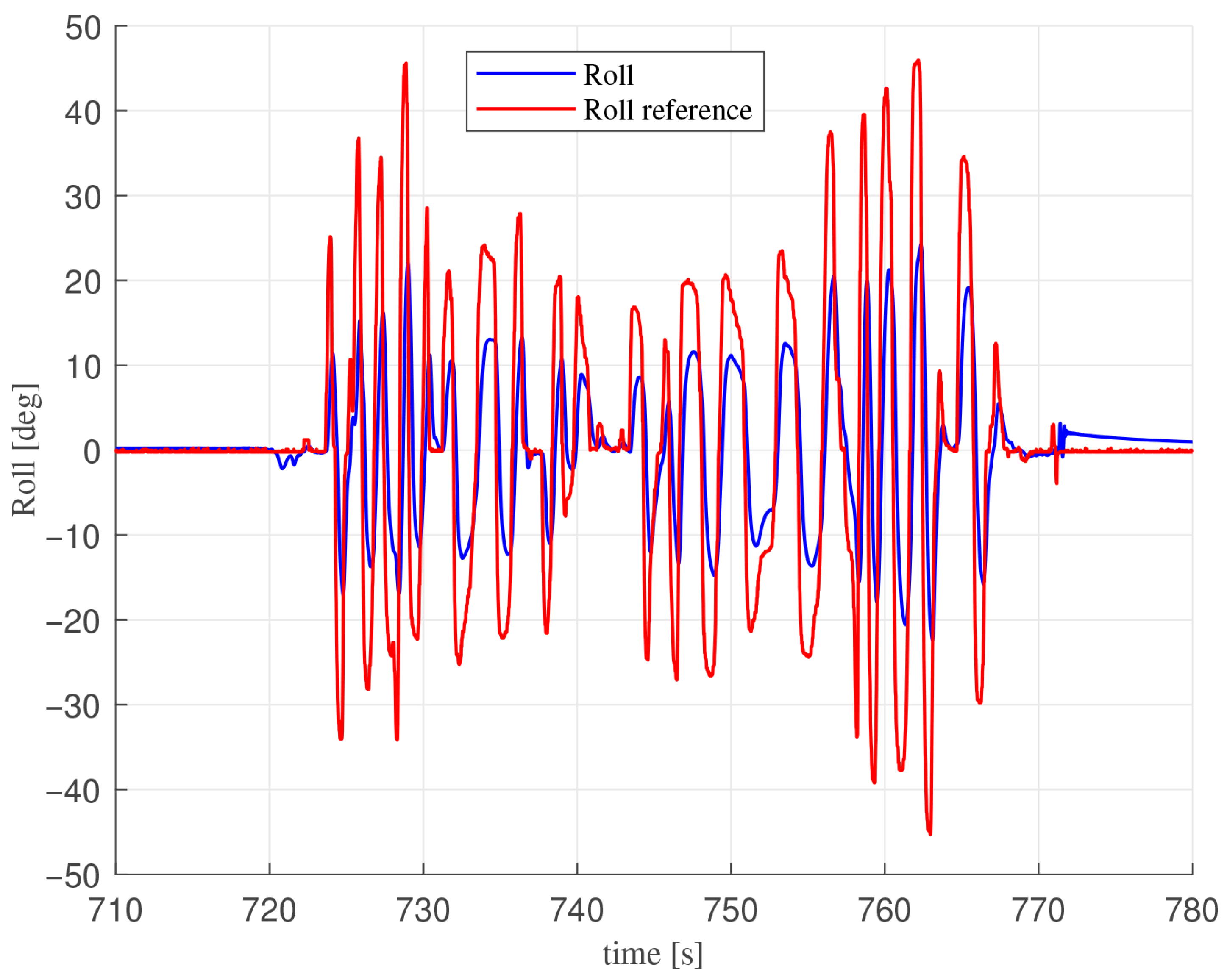
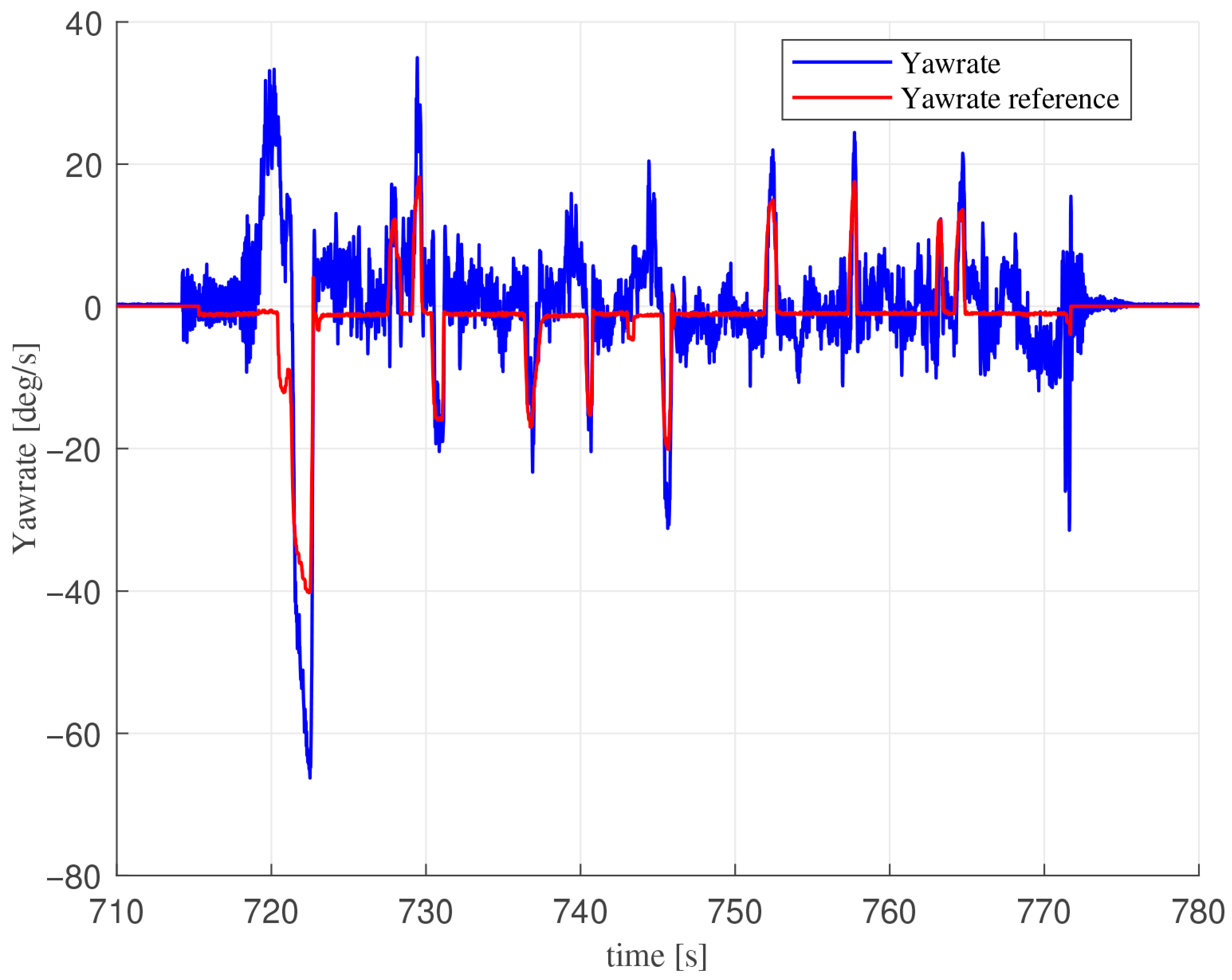
Just as an example, Figure 19, Figure 20 and Figure 21 show responses to pilot Roll, Pitch, and Yaw rate commands during a test flight.
Both Roll and Pitch show a good response to pilot commands following the reference signal, although, as expected, a small residual angular error appears to remain at steady state. The main purpose of the Yaw-rate controller is to compensate for disturbances generated by the non-perfect cancellation of the reaction torques exerted by rotating propellers. Experimental results prove that the Yaw-rate controller is able to fulfill this task. Overall, the control system is capable of achieving good performance, and the Catafalcon UAV displays good maneuverability and dynamic response.
From the pilot’s perspective, the vehicle turned out to be pleasant to fly, with the duct creating a good damping of lateral motions, making it more stable and easier to fly than the typical multirotor (that being “naked” in classical configurations possesses poor lateral motion damping); also, manual altitude control was very easy.

5. Conclusions

This paper successfully addressed the lack of commercially available ducted-fan platforms suitable for research activities by presenting a comprehensive design, manufacturing, and testing framework for Catafalcon, a fully 3D-printed ducted-fan UAV. The work demonstrates that a functional and flight-worthy ducted-fan vehicle can be realized using only commercial off-the-shelf electronics and 3D-printed components, making advanced UAV research more accessible to laboratories with limited budgets. The modular design approach adopted for Catafalcon proved highly effective, enabling easy component replacement and customization. All structural components, including the duct, the counter-rotating propellers, and the control deflectors, were successfully realized through fused filament deposition 3D printing using standard desktop equipment. The use of dovetail connections and segmented structures overcame the dimensional limitations of typical 3D printers, allowing the construction of a vehicle with a 37 cm duct diameter.
The propeller design process, based on Blade Element and Momentum theory, produced functional blades that, despite surface roughness inherent to 3D printing, demonstrated experimentally adequate performance. Experimental validation confirmed a thrust amplification factor of approximately 2.1 with respect to a single four-bladed propeller when operating within the duct, consistent with theoretical predictions and literature findings. While the design target of achieving hover at 50 % throttle was slightly missed, with actual hover occurring at approximately 60 % throttle, this outcome remains within acceptable margins and highlights areas for future optimization, particularly in blade surface finishing and manufacturing orientation. The basic attitude control system, implemented using proportional-derivative controllers for Roll and Pitch and a proportional-integral controller for Yaw rate, proved effective for stabilized flight during tests.
The lateral motion damping provided by the duct structure notably enhanced flight stability compared to conventional unducted multirotor configurations, confirming the design’s advantages for indoor and confined-space operations. The modular and accessible design philosophy of Catafalcon aligns with previous efforts in developing flexible autopilot systems, such as the ICARO platform, which emphasizes rapid prototyping and code portability across different vehicle types. The emphasis on safe human–robot interaction is inherent in the ducted-fan configuration through propeller protection. The control allocation strategy and simplified dynamic modeling approach presented connect to broader investigations in nonlinear control and adaptive systems for underactuated aerial vehicles, providing a solid foundation that could be enhanced with more sophisticated techniques. While this work successfully demonstrates the feasibility of 3D-printed ducted-fan UAVs, several limitations suggest further developments for future research. The current design operates slightly above the intended 50 % hover throttle point, indicating room for aerodynamic optimization through the systematic exploration of blade printing orientations, post-processing methods, and alternative materials to minimize surface roughness. Implementing outer-loop controllers for autonomous altitude, velocity, and position control would enable fully autonomous operation, while advanced control strategies could better handle modeling uncertainties and aerodynamic disturbances. Recent developments in adaptive control techniques for rotorcraft platforms offer particularly promising directions for enhancing Catafalcon’s capabilities. The application of adaptive control to helicopter speed regulation has demonstrated significant improvements in handling external disturbances and model uncertainties, providing reliable performance even under challenging conditions. Such adaptive approaches could be extended to ducted-fan platforms to enhance robustness during transitions between hover and forward flight or when operating in turbulent environments. Similarly, adaptive attitude augmentation techniques have shown effectiveness in compensating for coupled dynamics and atmospheric disturbances in small-scale unmanned helicopters, suggesting natural extensions to the attitude control system currently implemented on Catafalcon. These adaptive control methodologies could address the linearization limitations inherent in the current PD/PI control architecture [41,42,43], enabling more aggressive maneuvers while maintaining stability.
The Catafalcon project proves that ducted-fan UAV research can be conducted without expensive commercial platforms. By leveraging accessible 3D printing technology, off-the-shelf electronics, and established control theory, the modular architecture facilitates experimentation with different mechanical configurations, control strategies, and sensor payloads, while additive manufacturing enables rapid iteration cycles that would be prohibitively expensive with traditional fabrication methods. Our experimental results validate 3D printing as a practical approach for manufacturing critical aerodynamic components, including propellers and ducts, despite the surface finish limitations of current desktop printers. Successful flight demonstrations confirm that the simplified analytical models used in the design phase provide sufficient accuracy for this class of vehicles.

Author Contributions

Conceptualization, A.D.R., M.A., G.L., M.M., S.M. and L.P.; Methodology, A.D.R., M.A., G.L., M.M., S.M. and L.P.; Software, A.D.R., M.A., G.L., M.M., S.M. and L.P.; Validation, A.D.R., M.A., G.L., M.M., S.M. and L.P.; Formal analysis, A.D.R., M.A., G.L., M.M., S.M. and L.P.; Investigation, A.D.R., M.A., G.L., M.M., S.M. and L.P.; Resources, A.D.R. and L.P.; Data curation, A.D.R., M.A., G.L., M.M., S.M. and L.P.; Writing—original draft, A.D.R., M.A. and L.P.; Writing—review & editing, A.D.R., M.A. and L.P.; Visualization, A.D.R., M.A. and L.P.; Supervision, L.P.; Project administration, L.P.; Funding acquisition, L.P. All authors have read and agreed to the published version of the manuscript.

Funding

This research was partially supported by the Italian Ministry of Education and Research (MIUR) in the framework of the CrossLab and Forelab projects—“Departments of Excellence Programme”.

Institutional Review Board Statement

The authors declare that this manuscript is original: it has not been previously published or is being considered for publication elsewhere. The paper reflects the authors’ own research and analysis in a truthful and complete manner. The paper properly credits the meaningful contributions of co-authors and co-researchers. The results are appropriately placed in the context of prior and existing research. All sources used are properly disclosed (correct citation). All authors have been personally and actively involved in substantial work leading to the manuscript.

Data Availability Statement

Dataset available upon request from the authors.

Conflicts of Interest

The authors declare no conflicts of interest.

References

  1. Lipera, L.; Colbourne, J.D.; Tischler, M.; Mansur, M.H.; Rotkowitz, M.; Patangui, P. The Micro Craft iSTAR Micro Air Vehicle: Control System Design and Testing; American Helicopter Society International, Inc.: Fairfax, VA, USA, 2001; Volume 57, pp. 1998–2008. [Google Scholar]
  2. Cai, G.; Dias, J.; Seneviratne, L. A Survey of Small-Scale Unmanned Aerial Vehicles: Recent Advances and Future Development Trends. Unmanned Syst. 2014, 2, 175–199. [Google Scholar] [CrossRef] [Scilit]
  3. Saeed, A.S.; Younes, A.B.; Cai, C.; Cai, G. A survey of hybrid Unmanned Aerial Vehicles. Prog. Aerosp. Sci. 2018, 98, 91–105. [Google Scholar] [CrossRef] [Scilit]
  4. Binetti, P.; Daniel, T.; Pollini, L.; Innocenti, M.; Hamel, T.; Francois, L. Flight Control System of the HoverEye VTOL UAV; NATO Research and Technology Organization (RTO): Neuilly-sur-Seine, France, 2007; Volume RTO-MP-AVT-146. [Google Scholar]
  5. Hoffer, N.; Coopmans, C.; Jensen, A.M.; Chen, Y.Q. A Survey and Categorization of Small Low-Cost Unmanned Aerial Vehicle System Identification. J. Intell. Robot. Syst. 2014, 74, 129–145. [Google Scholar] [CrossRef] [Scilit]
  6. Yin, Z.; Pei, H. A Ducted Fan UAV for Safe Aerial Grabbing and Transfer of Multiple Loads Using Electromagnets. arXiv 2024, arXiv:2409.15822. [Google Scholar] [CrossRef] [Scilit]
  7. Nguyen, T.; Nguyen, N.; Kiem, H. Control system design and model development for a ducted-fan singlecopter. Sci. Technol. Dev. J. 2017, 20, 38–44. [Google Scholar] [CrossRef] [Scilit]
  8. Nemnem, A.F.; Zakaria, M.Y.; Elzahaby, A.M. Contra-Rotating Ducted Fan Aerothermodynamic Design Procedure for Unmanned Applications. In Proceedings of the AIAA SciTech Forum, American Institute of Aeronautics and Astronautics, Kissimmee, FL, USA, 8–12 January 2018; pp. 1–13. [Google Scholar] [CrossRef] [Scilit]
  9. Zakaria, M.Y.; Nemnem, A.F.; Gad, K.O.; Abdel Wahab, M.M. Performance Analysis and Aerodynamic Modeling of Contra-Rotating Ducted Fan UAV. In Proceedings of the AIAA SciTech Forum, American Institute of Aeronautics and Astronautics, San Diego, CA, USA, 7–11 January 2019; pp. 1–14. [Google Scholar] [CrossRef] [Scilit]
  10. Wei, W.; Wei, S.; Ke, Z.; Guo, M.; Shu, Y.; Meng, Q.; Jia, L.; Zhang, M.; Han, S. Optimizing the Aerodynamic Performance of a Duct–Rotor System for Drones: A Comprehensive Study on the Coupled Parameters. Drones 2025, 9, 45. [Google Scholar] [CrossRef] [Scilit]
  11. Goudswaard, R.; Ragni, D.; Baars, W. Effects of the rotor tip gap on the aerodynamic and aeroacoustic performance of a ducted rotor in hover. Aerosp. Sci. Technol. 2024, 155, 109734. [Google Scholar] [CrossRef] [Scilit]
  12. Manzoor, T.; Xia, Y.Q.; Ali, Y.; Hussain, K. Flight control techniques and classification of ducted fan aerial vehicles. Control Theory Appl. 2022, 39, 201–221. [Google Scholar]
  13. Marconi, L.; Naldi, R.; Gentili, L. Modelling and control of a flying robot interacting with the environment. Automatica 2011, 47, 2571–2583. [Google Scholar] [CrossRef] [Scilit]
  14. Cheng, Z.H.; Pei, H.L. Control Effectiveness Enhancement for the Hovering/Cruising Transition Control of a Ducted Fan UAV. J. Intell. Robot. Syst. 2022, 105, 89. [Google Scholar] [CrossRef] [Scilit]
  15. Feng, W.; Wu, Y.; Chen, Y.; Wang, Z. Dynamic analysis and CFD calculation of a differential control type for ducted fan UAV. In Proceedings of the 2014 International Conference on Modelling, Identification and Control, Melbourne, Australia, 3–5 December 2014; pp. 249–253. [Google Scholar]
  16. Xu, C.; Su, C. Dynamic observer-based H robust control for a ducted coaxial-rotor UAV. IET Control Theory Appl. 2022, 16, 1165–1181. [Google Scholar] [CrossRef] [Scilit]
  17. Goh, G.; Agarwala, S.; Goh, G.; Dikshit, V.; Sing, S.; Yeong, W. Additive manufacturing in unmanned aerial vehicles (UAVs): Challenges and potential. Aerosp. Sci. Technol. 2017, 63, 140–151. [Google Scholar] [CrossRef] [Scilit]
  18. Ferro, C.; Grassi, R.; Seclì, C.; Maggiore, P. Additive Manufacturing Offers New Opportunities in UAV Research. Procedia CIRP 2016, 41, 1004–1010. [Google Scholar] [CrossRef] [Scilit]
  19. Tanikella, N.G.; Wittbrodt, B.; Pearce, J.M. Tensile strength of commercial polymer materials for fused filament fabrication 3D printing. Addit. Manuf. 2017, 15, 40–47. [Google Scholar] [CrossRef] [Scilit]
  20. Shaqour, B.; Abuabiah, M.; Abdel-Fattah, S.; Juaidi, A.; Abdallah, R.; Abuzaina, W.; Qarout, M.; Verleije, B.; Cos, P. Gaining a better understanding of the extrusion process in fused filament fabrication 3D printing: A review. Int. J. Adv. Manuf. Technol. 2021, 114, 1279–1291. [Google Scholar] [CrossRef] [Scilit]
  21. Graf, W.; Fleming, J.; Ng, W. Improving Ducted Fan UAV Aerodynamics in Forward Flight. In Proceedings of the 46th AIAA Aerospace Sciences Meeting and Exhibit, Reno, NV, USA, 7–10 January 2008. [Google Scholar]
  22. Fung, P.H.; Amitay, M. Control of a Miniducted-Fan Unmanned Aerial Vehicle Using Active Flow Control. J. Aircr. 2002, 39, 561–571. [Google Scholar] [CrossRef] [Scilit]
  23. Schaller, D.F. A Technique for Shape Optimization of Ducted Fans. Master’s Thesis, Iowa State University, Ames, IA, USA, 2007. [Google Scholar]
  24. Valavanis, K.P.; Vachtsevanos, G.J. (Eds.) Handbook of Unmanned Aerial Vehicles; Springer: Dordrecht, The Netherlands, 2015. [Google Scholar]
  25. de Angelis, E.L.; Giulietti, F.; Rossetti, G.; Bellani, G. Performance analysis and optimal sizing of electric multirotors. Aerosp. Sci. Technol. 2021, 118, 107057. [Google Scholar] [CrossRef] [Scilit]
  26. Avanzini, G.; de Angelis, E.L.; Giulietti, F.; Minisci, E. Optimal Sizing of Electric Multirotor Configurations. In Proceedings of the MATEC Web of Conferences, EDP Sciences, Gdynia, Poland, 20–23 April 2018; Volume 233, p. 00028. [Google Scholar]
  27. Bogda, K.; Krusz, W.; Rodzewicz, M.; Rutkowski, M. Design and Optimization of a Low Speed Ducted Fan for a New Generation of Joined Aircraft; International Council of the Aeronautical Sciences (ICAS): Bonn, Germany, 2014. [Google Scholar]
  28. Ryu, M.; Cho, L.; Cho, J. The Effect of Tip Clearance on Performance of a Counter-Rotating Ducted Fan in a VTOL UAV. Trans. Jpn. Soc. Aeronaut. Space Sci. 2016, 60, 1–9. [Google Scholar] [CrossRef] [Scilit]
  29. Guerrero, I.; Londenberg, W.K.; Gelhausen, P.; Myklebust, A. A Powered Lift Aerodynamic Analysis for the Design of Ducted Fan UAVs. In Proceedings of the 2nd AIAA “Unmanned Unlimited” Conf. and Workshop & Exhibit, San Diego, CA, USA, 15–18 September 2003; pp. 65–67. [Google Scholar]
  30. Thiele, M.; Obster, M.; Hornung, M. Aerodynamic Modeling of Coaxial Counter-Rotating UAV Propellers; Vertical Flight Society: Mesa, AZ, USA, 2019; p. 343. [Google Scholar]
  31. Kim, W.Y.; Senguttuvan, S.; Kim, S.M. Effect of Rotor Spacing and Duct Diffusion Angle on the Aerodynamic Performances of a Counter-Rotating Ducted Fan in Hover Mode. Processes 2020, 8, 1338. [Google Scholar] [CrossRef] [Scilit]
  32. Moaad, Y.; Alaaeddine, J.; Jawad, K.; Tarik, B.; Lekman, B.; Hamza, J.; Patrick, H. Design and Optimization of a Ducted Fan VTOL MAV Controlled by Electric Ducted Fans. In Proceedings of the 8th European Conference for Aeronautics and Aerospace Sciences (EUCASS), Madrid, Spain, 1–4 July 2019. [Google Scholar]
  33. Bramwell, A.R.S.; Done, G.T.S.; Balmford, D.E.H. Bramwell’s Helicopter Dynamics; Elsevier: Amsterdam, The Netherlands, 2001. [Google Scholar]
  34. Abbott, I.H.; von Doenhoff, A.E. Theory of Wing Sections; Dover: New York, NY, USA, 1959. [Google Scholar]
  35. Pollini, L.; Innocenti, M.; Di Corato, F.; Cellini, M.; Franchi, M.; Mati, R.; Niccolai, V. The ICARO Autopilot: A flexible Controller for small Unmanned Air Vehicles. In Proceedings of the IMAV 09 Workshop, Amsterdam, The Netherlands, 14–16 September 2009. [Google Scholar]
  36. Hua, M.D. Contributions to the Automatic Control of Aerial Vehicles. Ph.D. Thesis, French National Centre for Scientific Research, Grenoble, France, 2009. [Google Scholar]
  37. Pflimlin, J.M.; Binetti, P.; Souères, P.; Hamel, T.; Trouchet, D. Modeling and attitude control analysis of a ducted-fan micro aerial vehicle. Control Eng. Pract. 2010, 18, 209–218. [Google Scholar] [CrossRef] [Scilit]
  38. Pollini, L.; Metrangolo, A. Simulation and Robust Backstepping Control of a Quadrotor Aircraft. In Proceedings of the AIAA Modeling and Simulation Technologies Conference and Exhibit, Honolulu, HI, USA, 18–21 August 2008. [Google Scholar]
  39. Ren, X.L.; Wang, C.H.; Yi, G.X. Ducted fan UAV hovering attitude control. In Proceedings of the 2011 International Conference on Electronic and Mechanical Engineering and Information Technology, Harbin, China, 12–14 August 2011; Volume 1, pp. 421–424. [Google Scholar]
  40. Deng, S.; Ren, Z. Experimental study of a ducted contra-rotating lift fan for vertical/short takeoff and landing unmanned aerial vehicle application. Proc. Inst. Mech. Eng. Part G J. Aerosp. Eng. 2018, 232, 3108–3117. [Google Scholar] [CrossRef] [Scilit]
  41. Bertolani, G.; Ryals, A.D.; de Angelis, E.L.; Pollini, L.; Giulietti, F. L1 Adaptive Control for Small-Scale Unmanned Helicopters: Enhancing Speed Regulation. Drones 2024, 8, 649. [Google Scholar] [CrossRef] [Scilit]
  42. Guerreiro, B.; Silvestre, C.; Cunha, R.; Cao, C.; Hovakimyan, N. L-1 Adaptive Control for Autonomous Rotorcraft. In Proceedings of the 2009 American Control Conference, St. Louis, MO, USA, 10–12 June 2009. [Google Scholar] [CrossRef] [Scilit]
  43. Bichlmeier, M.; Holzapfel, F.; Xargay, E.; Hovakimyan, N. L1 Adaptive Augmentation of a Helicopter Baseline Controller. In Proceedings of the AIAA Guidance, Navigation, and Control (GNC) Conference, Boston, MA, USA, 19–22 August 2013. [Google Scholar] [CrossRef] [Scilit]
Figure 1. Ducted-fan models. (a) Hovereye [4]. (b) Istar [1].
Drones 10 00165 g001
Figure 2. Catafalcon during test flight. The red rope is a safety device and is not in tension.
Drones 10 00165 g002
Figure 3. Main structural components with deflectors and propellers connected.
Drones 10 00165 g003
Figure 4. Final ducted-fan assembly.
Drones 10 00165 g004
Figure 5. One of the four legs of Catafalcon.
Drones 10 00165 g005
Figure 6. Blade angles and forces.
Drones 10 00165 g006
Figure 7. Final propeller’s blade design.
Drones 10 00165 g007
Figure 8. Dovetail connection.
Drones 10 00165 g008
Figure 9. Duct section.
Drones 10 00165 g009
Figure 10. Duct 3D-printed structural components.
Drones 10 00165 g010
Figure 11. Duct component coating process.
Drones 10 00165 g011
Figure 12. Deflector’s servomechanism.
Drones 10 00165 g012
Figure 13. Deflectors’ placement and generated forces. As an example, the lift force L 1 generated by deflector 1 tilted by angle γ is shown.
Drones 10 00165 g013
Figure 14. Yaw rate control system architecture.
Drones 10 00165 g014
Figure 15. Roll and Pitch control system architecture.
Drones 10 00165 g015
Figure 16. Two-blade propeller thrust.
Drones 10 00165 g016
Figure 17. Four-blade propeller thrust.
Drones 10 00165 g017
Figure 18. Propeller thrust comparison.
Drones 10 00165 g018
Figure 19. Pitch response.
Drones 10 00165 g019
Figure 20. Roll response.
Drones 10 00165 g020
Figure 21. Yawrate response.
Drones 10 00165 g021
Table 1. Propeller and deflector parameters.
Component Dimensions
minimum inner duct diameter37 cm
duct height13 cm
propeller disc diameter36.2 cm
θ r o o t 37 deg
θ t i p 9 deg
c r o o t 3 cm
c t i p 2 cm
r r o o t 3.5 cm
r t i p 18.1 cm
deflector height (chord)7 cm
deflector surface (single wing) S112 cm 2
Table 2. Controllers gains (∗ = unused).
Controller k p k i k d
Roll6*−1.3
Pitch6*−1.3
Yaw rate1.20.1*
Table 3. Propeller data.
Number of Blades50%100%
20.6 [kg]1.84 [kg]
40.96 [kg]2.7 [kg]
Disclaimer/Publisher’s Note: The statements, opinions and data contained in all publications are solely those of the individual author(s) and contributor(s) and not of MDPI and/or the editor(s). MDPI and/or the editor(s) disclaim responsibility for any injury to people or property resulting from any ideas, methods, instructions or products referred to in the content.