


Highlights
What are the main findings?
- A covert spoofing strategy that operates solely on external radar observations at inference without internal target state information redirected an unmanned aerial vehicle (UAV) to a target fake destination without triggering the PX4 flight control computer’s extended Kalman filter (EKF) integrity check.
- We verified full physical-layer operation on actual hardware, where real radiofrequency (RF) signals physically assume the tracking loop of the receiver and measured values are directly fused into the actual PX4 EKF, which cannot be tested through position-injection simulations that merely inject location coordinates.
What are the implications of the main findings?
- Such covert spoofing attacks must be evaluated on physical hardware because position-injection simulations that only inject position coordinates cannot reproduce the actual behavior of global navigation satellite system (GNSS) receiver spoofing via RF signals and firmware-level navigation filters.
- The policy learned in the simulation can directly apply to the actual hardware environment of a unmanned aerial vehicle without retraining, demonstrating that such learning-based covert spoofing attacks can be developed and deployed at a low cost.
Abstract
Global navigation satellite system (GNSS) spoofing has emerged as an effective countermeasure to address the growing threat posed by the malicious use of unmanned aerial vehicles (UAVs) against military and civilian infrastructure. Previous UAV redirection spoofing approaches relied on internal target information state or were limited to verification through software simulations. This study integrates a Zynq UltraScale+ radiofrequency (RF) system-on-chip multi-constellation GNSS spoofer with a soft actor–critic covert spoofing policy based on a dual-normalized innovation squared reward, providing an RF-level hardware-in-the-loop simulation closed-loop platform within an anechoic chamber and enabling real-time integration of an actual PX4-based Pixhawk flight control computer with a commercial GNSS receiver. Operating solely on external radar observations without internal-target UAV information, the policy redirects the UAV within a 20 m capture radius of the fake destination across three scenarios. During this process, the manipulated measurements do not violate the innovation gate of the extended Kalman filter (EKF) even when the GNSS spoofing signal deceives the receiver. Experiments confirmed that the EKF continues to fuse these spoofed signals with normal measurements, demonstrating that, in a physical hardware closed-loop environment, a learning-based covert spoofing policy can bypass flight control computer integrity checks and successfully redirect the UAV.
1. Introduction
In addition to the recent geopolitical conflicts such as the Russia–Ukraine war [1], the Syrian civil war [2], the Israel–Hamas conflict [3], and the US–Iran conflict [4], attacks on key military [5] and civilian infrastructure [6] using unmanned aerial vehicles (UAVs) continue to rapidly increase the global UAV threat. Defense systems designed to counter UAV threats can be broadly classified into hard-kill and soft-kill approaches [7,8,9]. Hard-kill systems directly neutralize targets using physical means such as nets or missiles, whereas soft-kill systems neutralize a UAV’s flight system through electronic warfare techniques such as jamming or spoofing. For instance, global navigation satellite system (GNSS) spoofing involves transmitting counterfeit navigation signals to deceive a UAV’s receiver, manipulating its position and flight path [10,11,12,13]. As demonstrated by cases such as Russian electronic warfare equipment deployed in Syria for neutralizing US military UAVs [2] and Iran capturing a US UAV through GNSS spoofing [14], controlling UAV trajectories via GNSS spoofing has proven to be an effective countermeasure in actual conflict zones, and spoofing attacks against aircraft and ships continue to be reported [15,16,17].
GNSS spoofing signals can be effectively utilized as a countermeasure primarily because of the structural weaknesses of GNSS: their signal structures are publicly known, and the signal power reaching the Earth’s surface is extremely low [18,19,20]. To overcome these limitations and obtain stable position estimates, most UAVs integrate GNSS with an inertial navigation system (INS), referred to as GNSS/INS navigation systems [21,22]. However, sophisticated GNSS spoofing techniques can deceive these integrated navigation systems, covertly manipulating the integrated navigation solution and consequently disrupting the normal flight of the UAV. Accordingly, active research is underway to use GNSS spoofing signals to alter and control UAV flight paths toward the desired target locations.
Related studies can be broadly categorized into four groups based on the type of spoofing algorithm. Early studies used classical controllers such as proportional–integral–derivative controllers to redirect the target receiver along a desired path [22,23,24], while numerous rule-based or greedy algorithms heuristically update spoofing signals by observing the responses of the target UAV [25,26,27,28,29]. Recently, optimization-based techniques such as model predictive control and genetic algorithms [30,31], as well as approaches that use reinforcement learning (RL) to train spoofing policies [21,32], have been reported. Table 1 presents a comparative analysis of these recent studies by focusing on technical characteristics such as spoofing algorithms applied to trajectory control, control loop structures, and the dependency on the dynamics of the target UAV and internal parameters of the GNSS/INS.
Table 1.
Comparison of recent studies on UAV trajectory control via GNSS spoofing.
Table 1 compares studies on GNSS spoofing redirection based on two key criteria: whether the spoofing redirection algorithm relies on the internal information of the target UAV and whether the validation phase extends to the actual hardware level beyond software simulation. A cross-analysis of these criteria highlights two limitations of the existing literature:
- (1)
- Dependency on internal target information: Most classical control-, rule-, and optimization-based model-based techniques [22,23,24,27,28,29,30,31] assume that the dynamic parameters of the target or detection thresholds of its internal extended Kalman filter (EKF) are known in advance. In actual engagement scenarios, an attacker cannot obtain the UAV’s internal information in advance.
- (2)
- Lack of hardware verification: RL-based techniques [21,32] address this dependency by learning policies that operate solely on external radar observations without relying on the internal information of the target. However, because verification in these studies was restricted to simulated environments, the efficacy of spoofing for actual physical navigation and control loops remains unproven.
Consequently, to the best of the authors’ knowledge, research focusing on approaches that can overcome the limitations of the two aforementioned criteria and are simultaneously independent of the target UAV’s internal information and closed-loop verification using actual hardware remain lacking.
Based on prior research, the authors independently developed two key technologies to address these gaps:
(1) A multi-constellation GNSS spoofer (hereinafter referred to as a “GNSS spoofer”) was implemented utilizing a multicore architecture based on the Zynq UltraScale+ radiofrequency system-on-chip (RFSoC), and its ability to manipulate the position of commercial GNSS receivers under both static and dynamic spoofing scenarios was demonstrated [33]. However, that study was limited to arbitrarily altering the navigation solution of the target receiver and did not propose an intelligent redirection algorithm for redirecting the flight path of a UAV using a GNSS receiver to a specific destination.
(2) We proposed a covert spoofing policy based on a soft actor–critic (SAC) [34], which applies a dual-normalized innovation squared (NIS) compensation structure that balances both the external NIS [18] estimated by the radar and the internal NIS of the UAV. This study confirmed that it is possible to effectively bypass the anomaly detection integrity checks of the EKF in a simulation environment while simultaneously redirecting a target UAV to a target destination with a high degree of probability. However, the verification was limited to a purely software-based environment, identifying closed-loop verification via hardware-in-the-loop simulation (HILS), which integrates a GNSS spoofer with a UAV flight control computer (FCC), as a future task.
This paper integrates these prior studies and proposes an RF-level HILS platform that integrates a simulation-verified SAC-based dual-NIS covert spoofing policy with an existing GNSS spoofer and PX4-based Pixhawk FCC in real time. This framework simultaneously satisfies the two requirements outlined earlier: independence from target-internal information and closed-loop verification using physical hardware on a single platform.
The main contributions of this study are as follows:
- Based on the inference results of the trained SAC policy, we generated real-time RF GNSS spoofing signals and implemented an integrated HILS system that linked a physical GNSS receiver and an FCC in a closed-loop configuration.
- We verified that the spoofing position inferred by an RL agent could successfully redirect the target UAV even with the FCC and its EKF in the loop by demonstrating spoofing scenarios in an actual RF closed-loop environment. This confirms that the policy learned in the simulation applies directly to the actual hardware without retraining.
- To address the limitations of existing simulations that only inject position errors, we experimentally demonstrated the mechanism by which RF spoofing signals in the physical layer bypass the EKF integrity check of the FCC and are fused into the navigation solution.
The remainder of this paper is organized as follows. Section 2 describes the GNSS spoofer, SAC-based dual-NIS covert spoofing policy, and overall HILS platform architecture. Section 3 describes the interfaces, data flow, and physical hardware integration of the proposed HILS platform. Section 4 presents and discusses the field verification results of the covert spoofing method. Finally, Section 5 concludes the paper.
2. System Architecture
2.1. GNSS Spoofer
Spoofing signals are generated using a Zynq UltraScale+ RFSoC-based GNSS spoofer proposed in a previous study [33]. Three ARM Cortex-A53 cores operating in independent real-time operating system environments calculate signal generation parameters in parallel for the global positioning system (GPS), GLONASS, and BeiDou constellations. These parameters are transmitted in real time to the signal generator in the programmable logic area, where they are synthesized into RF spoofing signals. In this process, hardware delay compensation ensures a timing synchronization accuracy of ~0.03 chips (30 ns) relative to the actual GNSS signals [33]. For a detailed design of the spoofing device hardware, signal models, and delay compensation procedures, refer to [33].
For a GNSS spoofing signal to deceive a GNSS receiver, it must hijack the target receiver’s tracking loop, which requires precise code phase synchronization with the authentic signal and transmission power that exceeds the authentic signal [23]. GNSS receivers track code phase using three correlators (i.e., early, prompt, and late) spaced at 0.5 chip intervals [18]. Consequently, the code-phase error of the spoofing signal must be within ~0.5 chips relative to the authentic signal, and the spoofing signal must be transmitted with higher power than the authentic signal for the tracking loop to track the spoofing signal and receive it [10,35]. This spoofer possesses a temporal synchronization accuracy of ~0.03 chips, fully satisfying this spoofing condition; thus, it receives an authentic GNSS signal to align the code phase and determine the transmission timing of the spoofing signal.
2.2. Covert Spoofing Policy: SAC with Dual-NIS Reward
The covert spoofing policy implemented on this platform uses an SAC algorithm based on the dual-NIS reward, which was proposed and trained in our previous work [36]. We only briefly describe key elements essential to the HILS validation and results analysis; detailed trajectory generation processes and agent training procedures are provided in [36].
The spoofing problem is formalized as a Markov decision process defined by five tuples: state space , action space , transition probabilities , reward function , and discount rate γ. Here, represents a model-free environment where the internal dynamics of the UAV are unknown, and γ follows the standard SAC setup. This section describes only , , and , which are necessary to interpret the results.
The state vector sk observed by the agent at the kth step is a nine-dimensional normalized vector based on the target state estimated externally by the attacker, as defined as follows:
The state vector includes geometric information, estimation indicators, and velocity errors. As relative geometric information based on radar observations, it includes the normalized distance to the UAV , azimuth , and elevation . The relative angle between the true and fake destinations based on the estimated UAV position is defined as , whereas the relative angle based on the fake position is defined as . This incorporates the externally estimated NIS index and normalized UAV velocity , and it is represented by the velocity vector error between the current heading of the UAV and the direction of each destination. In this simulation environment, radar observations were simulated using an estimation filter that applied Gaussian observation noise to the true UAV position, instead of integrating physical equipment.
The agent’s action vector ak is output as a spoofing position offset in the spherical coordinate system and includes the magnitude of the offset ρk, azimuth θk, and elevation ψk, as follows:
Covertness is quantified based on NIS, which is an anomaly detection metric applied for navigation filters. For measurement innovation defined as the difference between the measured and predicted values and its covariance Sk, NIS is defined as follows:
An anomaly was detected if the value exceeded the 95% threshold TNIS of the chi-square distribution with three degrees of freedom, as follows:
The reward function rk has a dual-NIS structure, as follows:
This structure is composed of position redirection to the fake destination , velocity direction alignment reward , external NIS-based covertness term predicted from radar observations, NIS-based covertness term from the UAV’s internal navigation filter, and arrival-based termination reward . In addition, α1, α2, α3, and α4 represent the relative weights of each term; the specific values are taken from [36].
The external NIS-based reward is calculated entirely from the radar estimation filter and is used as observational information during both the training and inference phases. In contrast, the UAV’s internal NIS compensation is applied exclusively during the training phase to ensure that the agent achieves perfect covertness, which is not required during actual inference or deployment phases. Therefore, once training is complete, the policy can perform covert spoofing based solely on external observations without relying on internal target information.
The NIS metric used to optimize covertness during the learning phase is based on a mathematically defined ideal model. In contrast, the EKF of the FCC onboard the target UAV evaluates measurement innovations and performs integrity checks according to the internal criteria defined in the firmware [18,37]. The integrity check criteria within the firmware do not perfectly match the ideal NIS model defined in the simulation environment, and therefore, separate verification is required to determine if the covertness achieved at the simulation level is maintained in the actual hardware-based control loop.
2.3. Overall HILS Architecture
This section describes the overall architecture of an RF-level HILS platform, which integrates the simulation-trained SAC-based covert spoofing policy with actual GNSS signal generators, GNSS spoofers, and FCC in real time. The platform was designed based on the HILS mode of open-source firmware PX4 [38]. However, unlike the PX4’s standard hardware-in-the-loop (HITL) approach, which injects GNSS measurements generated by the simulator into the navigation filter, this study extends the system using RF signals received by an actual GNSS receiver through an antenna as the navigation inputs. As mentioned in Section 1, a significant number of existing studies on UAV trajectory control using GNSS spoofing have been limited to verification at the software simulation level. In these studies, researchers obtained the estimation results by directly injecting position measurements into arbitrarily assumed navigation filter models. In contrast, this platform transmits the calculated spoofing position as actual physical RF signals, thereby causing the tracking loop of the target receiver to track the spoofing signal. Using this approach, we empirically verify if the entire spoofing process from RF signal tracking to navigation solution manipulation is valid in the physical layer.
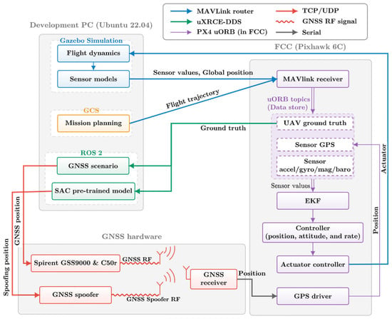
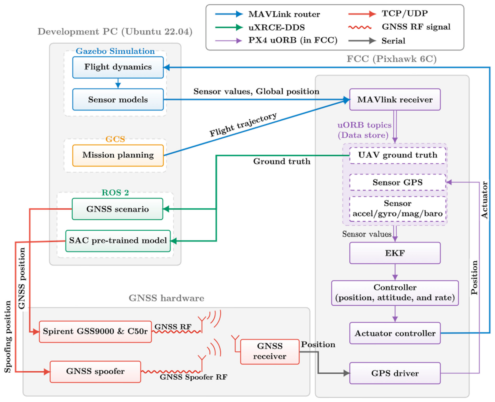
The entire system includes three components, as illustrated in Figure 1. The first is a simulation and policy layer that operates in the personal computer (PC) development environment. This layer includes Gazebo [39], a physics simulator; a ground control station (GCS), which handles mission planning; and a robot operating system 2 (ROS 2) [40], which is a robot software framework. Gazebo simulated the flight dynamics of the UAV in real time and the data from navigation sensors such as an inertial measurement unit (IMU), magnetometer, and barometer. QGroundControl [41] was used as the GCS to set flight paths based on predefined mission plans, whereas ROS 2 performed the inference of the pretrained SAC policy and transmitted the target coordinates to the GNSS simulator and spoofer.
Figure 1.
Overall architecture and closed-loop signal flow of the RF-level HILS covert GNSS spoofing platform.
The Pixhawk 6C hardware equipped with PX4 firmware at the FCC layer computes EKF and the attitude and position control algorithms. At this stage, the navigation filter within the firmware performs an innovation-based integrity check on each incoming GNSS measurement, discarding any signals that fall outside the acceptable range. This indicates that the hardware performs checks based on the same principle as the NIS, which the agent uses as a covertness optimization metric during the training phase.
The GNSS signal layer includes a GNSS simulator that emulates normal satellite signals and a GNSS spoofer that generates spoofing signals. The RF signals generated by these two devices are radiated and coupled inside an RF anechoic chamber and applied to the commercial GNSS receiver mounted on the target UAV. The specific hardware configuration and system integration methods for this signal layer are described in Section 3.2.
The real-time closed-loop operational flow of the entire system is as follows: Virtual sensor measurements generated by Gazebo were transmitted to the FCC via MAVLink [42], which is a standard UAV communication protocol, and they were used as inputs for the EKF and the controller. Simultaneously, Gazebo calculated the ground truth, which represented the actual position of the aircraft within the simulation environment. This ground truth was transmitted to the policy node on the development PC via the uXRCE-DDS middleware [43], which connected FCC and ROS 2. As described in Section 2.2, Gaussian observation noise was added to the ground truth to form the radar observation provided to the SAC agent. The agent inferred the spoofing offset from this observation, and the offset was added to the ground truth to form the target coordinates for the spoofer. The hardware spoofer generated a corresponding precise GNSS spoofing signal, which was spatially coupled wirelessly with the normal satellite signal transmitted by the Spirent simulator inside the RF anechoic chamber and applied to the GNSS receiver onboard the UAV. The receiver converted this into GNSS measurements and transmitted them to the FCC, which the EKF misinterpreted as normal signals, successfully spoofing the UAV’s position estimate.
Ultimately, the actuator control commands calculated using the spoofed position estimate were fed back into Gazebo’s dynamic model because the FCC controls the flight based on the manipulated position estimate, causing the UAV to move physically in the direction intended by the attacker. As the UAV moved, the updated ground truth was transmitted back to the policy node via FCC, completing the closed-loop system.
3. Hardware-in-the-Loop Platform
3.1. System Interfaces and Data Flow
The HILS platform was run on a host running Ubuntu 22.04 and deployed in a Docker container environment to ensure reproducibility. This container was created using the px4io/px4-dev-ros2-foxy [44] image, which includes the Gazebo Classic 11 [39], ROS 2 Foxy [40], and ARM toolchain. Through the running container, simulation, policy inference, and PX4 firmware [45] builds were performed in a single environment. The serial device of the host was exposed to the container, directly connecting the physical Pixhawk 6C and facilitating communication between the development PC and FCC in real-time via uXRCE-DDS [43] and the MAVLink router [46].
Table 2 summarizes the main communication links and data flows that comprise this platform; all transmission cycles listed in the table are actual measurements obtained from the implemented platform. The data-update cycles within the system were set according to the default update cycles of each interface. For the Gazebo–FCC segment, which requires the fastest cycle, simulated IMU measurements and ground-truth data were transmitted to the FCC via the MAVLink protocol at 250 Hz. Meanwhile, geomagnetic data were updated at 100 Hz and barometric data at 50 Hz and subsequently merged into the inertial measurement frame and transmitted. Conversely, the actuator commands generated by the FCC were fed back to Gazebo at a rate of 200 Hz.
Table 2.
Key interfaces and data flows of the HILS platform.
The telemetry segment connecting the FCC and ROS 2 policy nodes is subject to the bandwidth limitations of a serial-based wired link. To prevent communication delays that occur when short-cycle data are transmitted without changes, the 69 default topics in the uXRCE-DDS middleware were reduced to the number necessary for communication, and the publishing cycle was limited to 10 Hz. This 10 Hz limit applied only to the policy input and logging segments. The UAV’s flight control loop, comprising the IMU and GNSS, operated at its original cycle; therefore, it did not affect the actual flight. Consequently, the GNSS position and EKF integrity monitor values (ground truth data essential for policy inference and logging data for post-flight performance evaluation) were transmitted to the ROS 2 node at a 10 Hz cycle. Among these, Gaussian observation noise was added to the ground truth to form the radar observation for the SAC agent, whereas the raw ground truth was relayed to the Spirent simulator via the transmission control protocol (TCP) to synchronize the normal GNSS signal trajectory.
Finally, the ROS 2 policy node transmitted the spoofed position inferred by the agent to the GNSS spoofer, generating a GNSS signal corresponding to the spoofed position. The inference cycle of the agent was 1 Hz, which was slower than the 5 Hz navigation solution output cycle of the GNSS receiver. The output of the inferred SAC policy was transmitted at a 5 Hz rate using the zero-order hold (ZOH) technique to synchronize with the 5 Hz cycle of the GNSS receiver. The generated spoofing and normal signals synthesized by the Spirent simulator were spatially combined within the RF anechoic chamber and applied to a GNSS receiver mounted on the target UAV. Finally, the position solution calculated from the GNSS RF signal received by the receiver was transmitted to the FCC at a 5 Hz rate via the UBX protocol and fused with the navigation filter measurements, enabling the HILS system to operate in a closed-loop configuration. Because the integrity monitor telemetry was logged at 10 Hz while the GNSS solution was fused at 5 Hz, every GNSS fusion update and its accept or reject outcome were recorded in the log.
3.2. Hardware Integration
This section describes the hardware integration approach for combining spoofing policies learned in the simulation environment with a GNSS spoofer and FCC in a real-time closed-loop system. The development of this platform is a key contribution of this study because it overcomes the limitations of previous research, which was confined to simple algorithm verification. Further, it demonstrates the effectiveness of covert spoofing in an RF environment incorporating physical hardware. The target UAV used in this platform is the 3DR Iris model, which is Gazebo’s standard quadcopter; it is simulated based on the full 6-degree-of-freedom dynamics and PX4’s cascaded control architecture. This contrasts with the environment of a previous study [36], which approximated the UAV as a point-mass translational model with a fixed attitude and a PD controller to train the policy. This confirms that the attitude and rotor dynamics of the UAV abstracted during the training phase directly affect the actual closed-loop control process.
3.2.1. Physical Integration in the RF Anechoic Chamber
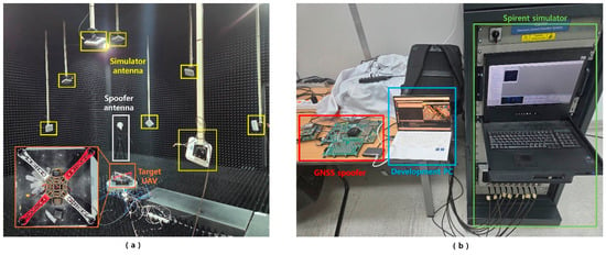
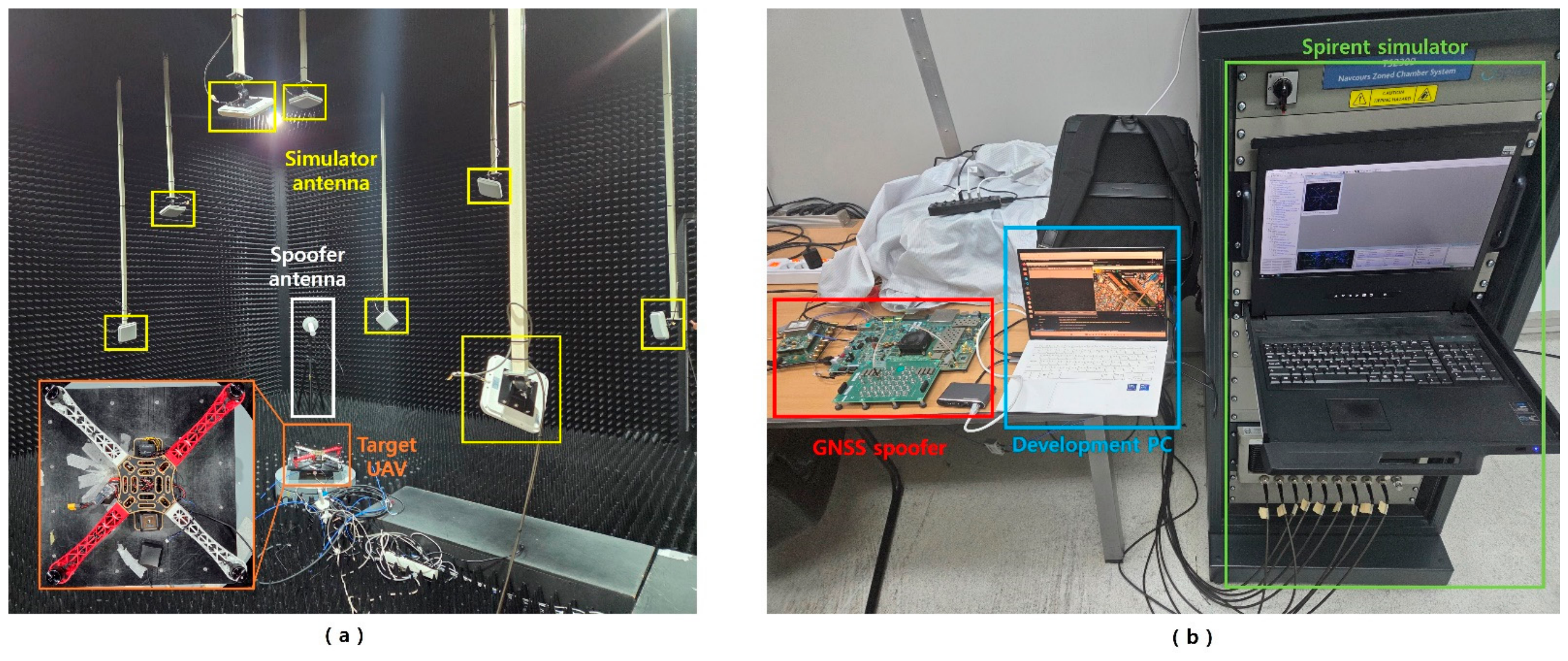
The entire hardware system was set up in an RF anechoic chamber (Figure 2) to create a test environment in which the leakage of spoofing signals to the outside and interference with GNSS signals were effectively blocked. Figure 2a shows the interior of the RF anechoic chamber, which contained eight simulator antennas that transmitted normal GNSS signals, a spoofing antenna that transmitted spoofing signals, and a target UAV. The simulator antennas were arranged to mimic the geometric configuration of the actual satellites, whereas the spoofing antenna was installed separately on the ground. The target UAV was positioned at the center of the chamber, where the antennas were directed, and the GNSS receiver installed on the target UAV was a Holybro Micro M8N. The Holybro Micro M8N can receive only GPS L1 data.
Figure 2.
Physical integration of the RF-level HILS testbed. (a) RF anechoic chamber: target UAV, distributed antennas that radiate the authentic GNSS signals, and spoofer antenna. (b) Signal generation and control equipment: RFSoC-based GNSS spoofer, development PC, and Spirent GNSS simulator.
Figure 2b includes a Spirent simulator that generates normal GNSS signals, a GNSS spoofer that generates GNSS spoofing signals, and a PC that controls them. The Spirent simulator includes a GSS9000 series [47] as the signal generator and is equipped with a C50r as the control PC. Using the SimGEN [47] control software to configure the simulator path, a signal containing the ground truth position estimate of the UAV was generated, and only the GPS L1 band was activated considering the operational specifications of the GNSS receiver onboard the UAV. The GNSS spoofer was implemented using a ZCU111 board, which is a Zynq UltraScale+ RFSoC. As described in [33], precise GNSS spoofing signals can only be generated by synchronizing with the normal GNSS signal; therefore, the device directly receives the signal emitted by the GSS9000 to synchronize with the 1 pulse-per-second time reference. Through this process, the system achieved a precise code phase synchronization condition of ~0.03 chips, as described in Section 2.1. The development PC serves as the host running the px4io/px4-dev-ros2-foxy container on which the Gazebo simulation and SAC policy nodes are executed.
3.2.2. Decoupled Sensor Injection and Coordinate-Frame Alignment
In the PX4’s HITL simulation mode, all sensors, including the GNSS, transmit the virtual measurements generated by the Gazebo simulator to the FCC. This platform blocks the injection of Gazebo’s virtual GNSS navigation solutions and extends the system to replace them with measurements from a real GNSS receiver that receives the actual RF signals in a physical radio wave environment. Consequently, inertial, geomagnetic, and barometric sensors are supplied by the physical simulator, whereas the position solution comprises actual measurements from the GNSS receiver.
This separate injection of sensor data is implemented by making minor modifications to the PX4 “mavlink_receiver” module. In the standard PX4 HITL mode, HIL_GPS messages, which are the navigation solution data transmitted by the Gazebo simulator, are accepted unconditionally and fed into the navigation filter. In contrast, in this study, we configured PX4’s HITL mode such that HIL_GPS was not accepted and a real GNSS receiver served as the sole source of position measurements. This modification does not affect the injection paths for the virtual inertia, magnetometer, and barometric measurements or the ground truth. Therefore, the remaining sensor layers supplied by the physical simulator remain unchanged.
Furthermore, the alignment of the coordinate system origins must be considered because of the separate injection of sensor data. In practice, FCC EKF sets the first acquired GNSS position as the origin of the local coordinate system. The initial GNSS measurement on this platform is a signal generated by the simulator, and therefore, the origins of the GNSS simulator scenario and Gazebo simulation must coincide exactly. If there is even a slight discrepancy between these coordinate systems, errors accumulate between the position integrated by the INS and the position indicated by the GNSS solution, resulting in an integrity error that causes EKF to continuously reject GNSS fusion. This system prevents fusion–rejection issues by precisely aligning initial coordinate systems.
4. Results and Discussion
4.1. Experimental Setup
We demonstrated the covert spoofing performance of the RF-level HILS platform described in Section 3 using the SAC-based dual-NIS policy proposed in prior research [36]. In the experimental scenario, the UAV performed autonomous flight toward a preplanned true destination, and the attacker redirected it toward three fake destinations. All coordinates followed the north-east-down frame with the takeoff point as the origin. Spoofing is dominant in the horizontal plane; therefore, only the horizontal components of the coordinates were specified and the altitude was held constant throughout the flight.
- Case A: True destination (0, 1200) m → fake destination (200, 900) m;
- Case B: True destination (1200, 0) m → fake destination (800, −200) m;
- Case C: True destination (1200, 0) m → fake destination (800, 200) m.
The measured data were collected in an RF anechoic chamber using a single GNSS receiver tuned to the GPS L1 C/A band. Each session was initiated after undergoing an independent hardware initialization procedure. The success of each trial was assessed against two independent criteria that were evaluated and reported separately. The first criterion, redirection, was satisfied when the UAV’s ground-truth trajectory entered within a 20 m radius of the fake destination. The second criterion, covertness, was satisfied when no GNSS horizontal-position measurement was rejected by the EKF’s innovation gate while the spoofing was active.
The covertness of the spoofing was quantified using axis-specific test ratios, which served as criteria through which the actual EKF determined whether to accept each measurement. The test ratios for the horizontal plane (north and east) γN and γE are defined as
where νN and νE represent the components of the measurement innovation along the corresponding axis, SNN and SEE represent the diagonal component of the innovation covariance matrix along the corresponding axis, and g represents the gate parameter that determines rejection. In this validation, g was maintained at the PX4 default value for the GNSS horizontal position (5.0), and all other EKF parameters were maintained at the defaults of PX4-Autopilot v1.17.0 [45], ensuring that the covert redirection was evaluated on the default firmware configuration running on an actual UAV. If the test ratio γN or γE exceeded the rejection threshold of 1.0 for the two axes in the horizontal plane, the corresponding measurement was considered an outlier and rejected. These test ratios and rejection rules were not arbitrarily defined in this study. Instead, they were adopted directly from the gating algorithm used by PX4’s EKF to filter outliers before fusing each GNSS measurement [37].
Unlike the NIS-based criterion used for training in Equation (3), which applies a chi-square threshold of approximately 7.815 to the full three-dimensional innovation vector, the innovation gate of this EKF evaluates each horizontal axis separately from the diagonal covariance and allows a standardized squared innovation of up to g2 = 25 per axis. The EKF innovation gate therefore uses a more permissive rejection criterion, and a policy that remains covert under the NIS-based criterion used during training should satisfy it. The hardware measurements were evaluated directly with respect to this gate.
The main operating conditions of the experiment were as follows. The spoofing policy inferred a position offset at 1 Hz, which was then transmitted at 5 Hz using the ZOH method. The change in offset per inference cycle was limited to a maximum of 1.8 m, ensuring that the spoofed position changed gradually instead of jumping significantly. Because the redirection was governed by the 1 Hz inference and the 5 Hz transmission only aligned the spoofed position with the receiver’s update cycle rather than adding control information, the update rate did not affect the accuracy or reliability of the redirection. The UAV flew along its route in the auto-mission mode at a cruising speed of 5 m/s. For each scenario, the number of trials was fixed in advance at 20. Each trial was preceded by an independent hardware reinitialization procedure. All metrics were computed over the airborne phase of the flight, during which the spoofing was active. The success rates are reported with 95% Wilson confidence intervals, which remain reliable at small sample sizes [48].
4.2. Covert Redirection
In all three scenarios, the learning policy redirected the UAV to a fake destination without violating the EKF integrity check. To quantify this behavior, each scenario was repeated N = 20 times, and the aggregate outcomes are summarized in Table 3. Redirection succeeded in 20/20, 19/20, and 19/20 trials for Cases A, B, and C, respectively. Across all three scenarios, none of the 111,981 GNSS horizontal-position samples recorded while the spoofing was active was rejected by the EKF innovation gate. The two trials that did not reach the capture radius still satisfied the covertness criterion.
Table 3.
Per-scenario evaluation over N = 20 trials. The redirection and covertness criteria are reported separately; confidence intervals are 95% Wilson intervals. The rejected-samples count is pooled over the 20 trials of each scenario, taken from the GNSS horizontal-position samples logged over the airborne phase.
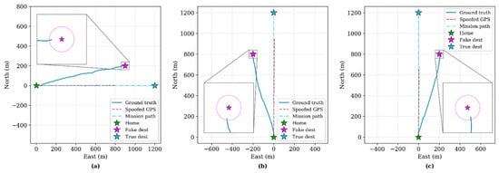
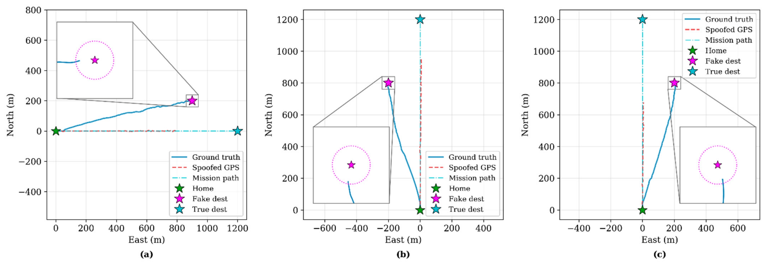
Figure 3 shows the measured trajectories for the three scenarios. The UAV maintained its initial mission course along the mission path before being diverted by the spoofing signal toward each fake destination, ultimately entering the 20 m capture radius for each fake destination. In contrast, the manipulated GNSS trajectory remained close to the flight mission path, suggesting that the position reported by the receiver appeared normal even when the spoofing operation was underway.
Figure 3.
Ground truth trajectories of the representative (median) session for the three covert-redirection cases: (a) Case A, (b) Case B, and (c) Case C. The UAV (blue) departed toward the true destination; however, it was redirected into the 20 m capture radius of the fake destination while the spoofed GNSS track (red dashed) remained close to the true course.
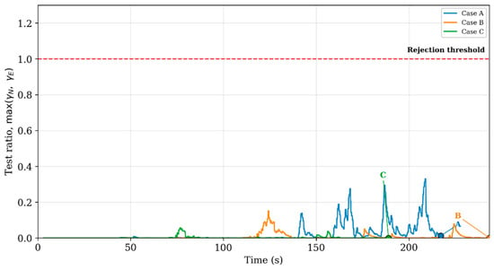
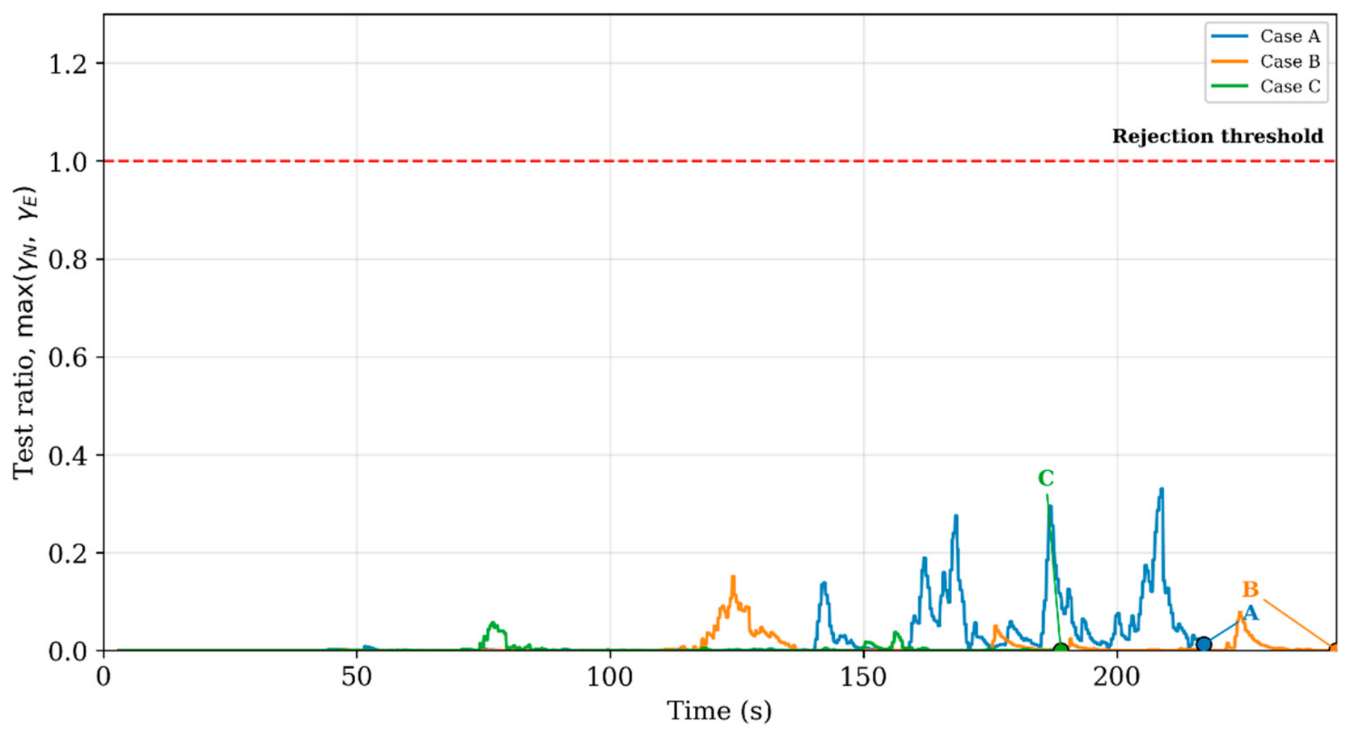
During trajectory redirection, spoofed GNSS measurements were not rejected by the navigation filter during any successful session. Figure 4 shows the superimposed trends of the maximum envelope curves for γN and γE across all three successful sessions. The endpoints of each curve correspond to the time at which the respective case ended. All three curves exhibit stable values below the rejection threshold of 1.0 throughout the entire scenario, demonstrating that the proposed spoofing strategy was effectively concealed at the actual EKF level.
Figure 4.
Test ratio envelope max (γN,γE) for the representative (median) session of the three successful cases. All three maximum envelope values remained well below the rejection threshold (γ = 1.0) throughout the runs. The spoofed horizontal-position measurements were not rejected by the EKF’s innovation gate.
Table 4 summarizes the quantitative metrics of three representative successful sessions. The cumulative spoofing offset reached peaks of more than 200 m in all three sessions, while the EKF within the FCC accepted the displaced measurements as normal and incorporated them into the fusion.
Table 4.
Quantitative summary of a representative (median) session for each case. Peak offset is the maximum horizontal distance between the spoofed position and ground truth over the run. Max γ represents the peak of max (γN,γE).
In the repeated trials for each scenario, covert redirection was consistently observed, indicating that the stochastic policy sustained its redirection performance even in the HILS environment. However, in some sessions, instances were observed in which the target UAV could not be redirected to the fake destination.
4.3. Failure Mode
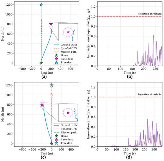
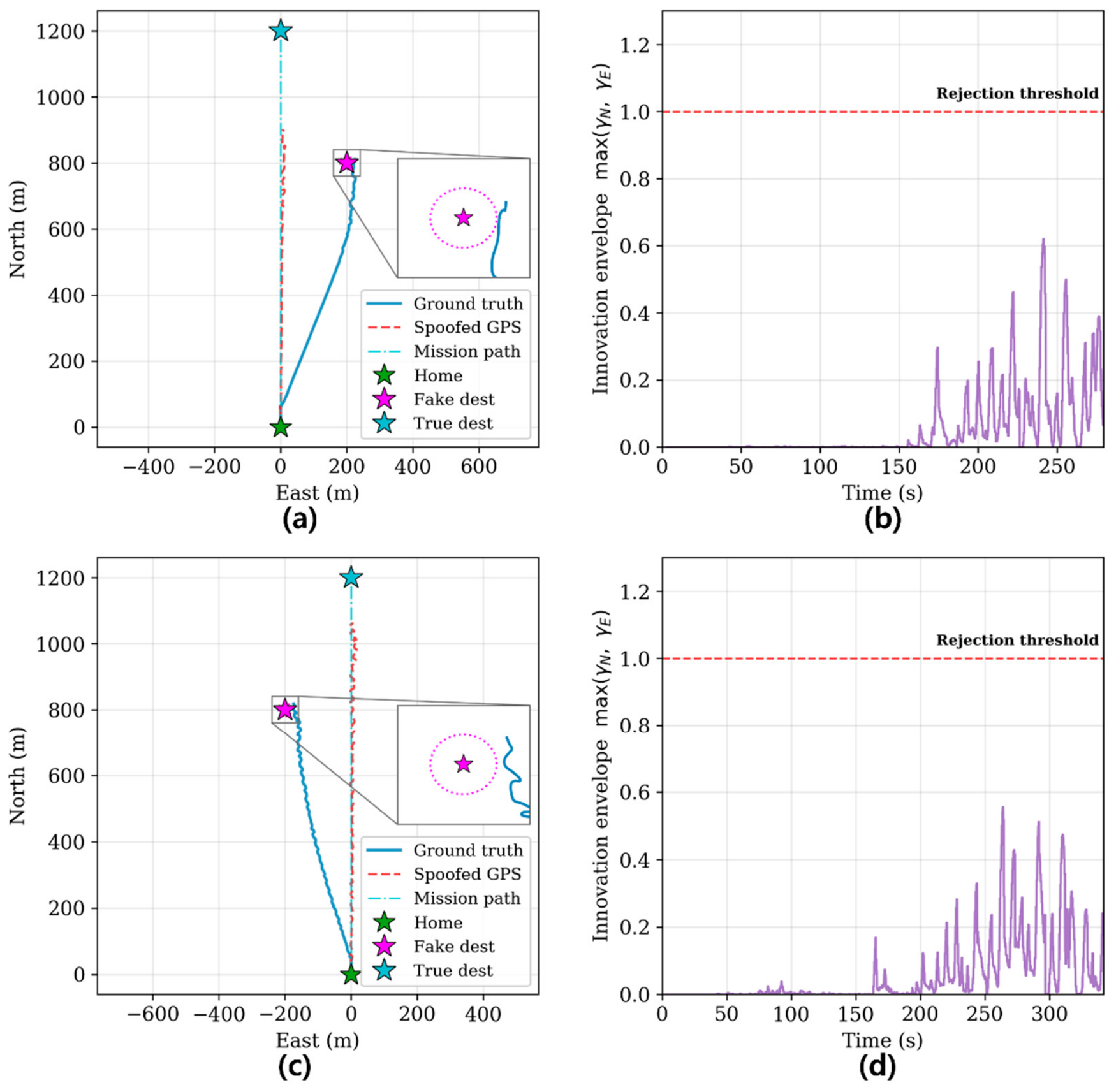
In this validation, two of the 60 trials were observed in which the spoofing remained covert but physical redirection failed. The flight trajectories and test ratio trends for these two cases are displayed in Figure 5.
Figure 5.
Two failed redirection trials from the repeated experiments. (a,c) The ground-truth trajectory passed the fake destination, missing the 20 m radius by 21.5 m and 24.7 m, respectively. (b,d) Innovation envelope max (γN,γE) during the covert spoofing; in both trials it remained below the rejection threshold (γ = 1.0) throughout.
In the Case C (Figure 5a,b) and Case B (Figure 5c,d) scenarios, the UAV followed the spoofing signal and approached the fake destination but failed to enter the 20 m radius, by margins of 21.5 m and 24.7 m, respectively, and flew past it. Furthermore, as indicated in Figure 5b,d, the innovation envelope peaked at approximately 0.6 in both trials and did not reach the rejection threshold throughout the entire flight segment. Thus, even though both layers (manipulation of GNSS measurements and passing the EKF integrity check) functioned as intended, the spoofing policy failed to redirect the actual trajectory into a fake destination by the end of the policy period. This is because the integrity check determines only whether each spoofed measurement is accepted and fused into the position estimate, and the resulting physical trajectory is then shaped by both the FCC’s response to that estimate and the UAV dynamics. Because the offset shifted gradually (within 1.8 m per inference cycle) to remain covert, the redirection that accumulated during the policy period was insufficient, and the cruise inertia of the UAV caused the actual trajectory to pass the fake destination. The same failure to reach the fake destination had been observed in the prior simulation study [36], and it manifested in the same manner in the present HILS setting, with the FCC and its EKF in the loop and the UAV dynamics simulated in Gazebo.
4.4. EKF Fusion Analysis
The physical RF closed-loop verification revealed the behavior of the actual RF signal path and firmware navigation filter that position-injection simulations do not model. During a successful session, the cumulative spoofing offset grew to over 200 m, indicating that the EKF within the firmware recognized the displaced measurement as valid and fused it into the estimate. This is because the integrity check of the EKF gates considered only the innovation at each update point rather than the cumulative absolute offset relative to the ground truth. This policy limits the offset change per decision cycle to a maximum of 1.8 m, gradually shifting the spoofed position. Therefore, the innovation for each epoch does not exceed the rejection threshold even as the cumulative offset becomes large, enabling the measurements to continue to be fused.
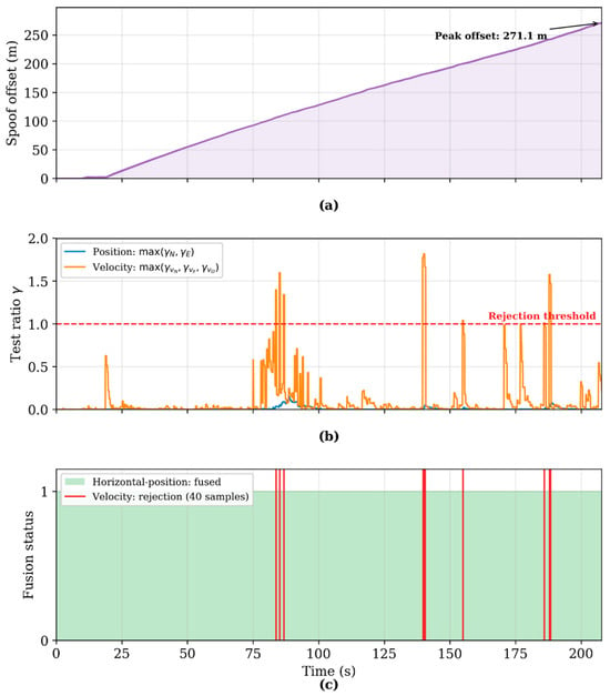
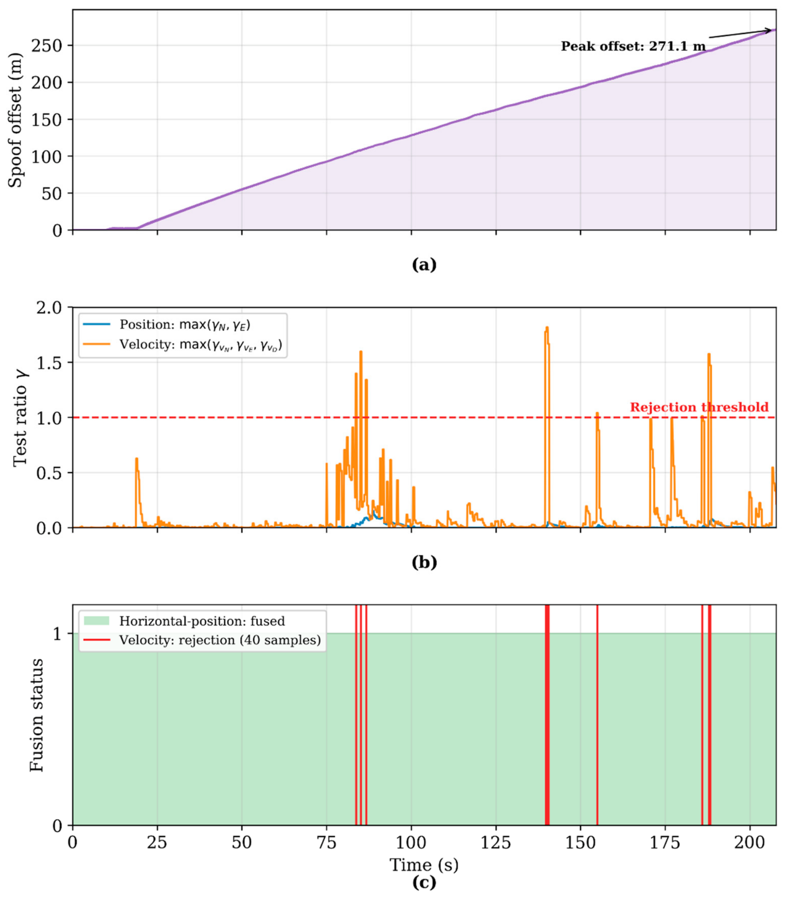
Figure 6 illustrates this pattern for the representative (median) session of Case B. As shown in Figure 6a, the cumulative spoofing offset increased continuously, reaching 271 m. In Figure 6b, the horizontal-position test ratio max (γN,γE) remained below the rejection threshold throughout, whereas the velocity test ratios γvN,γvE, and γvD, which correspond to the north, east, and down velocity components, occasionally exceeded the threshold. Whenever a velocity test ratio exceeded the threshold, the velocity measurement was rejected, as shown in Figure 6c, while the horizontal-position measurement was fused at every sample without rejection.
Figure 6.
Synchronized EKF fusion log for the representative (median) session of Case B. (a) Cumulative spoofing offset relative to the ground truth, reaching a peak of 271.1 m. (b) Test ratios of the horizontal-position channel max (γN,γE) and the velocity channel max (γvN,γvE,γvD) relative to the rejection threshold (γ = 1.0). (c) GNSS horizontal-position fusion status and velocity rejection samples.
The velocity rejections arose from how the spoofed velocity is produced. Because the policy manipulates only position, the velocity reported in the spoofed GNSS measurement is computed as the time derivative of the spoofed position offset. This keeps the position and velocity mutually consistent, but the gradual ramp of the offset occasionally produced a velocity innovation that exceeded the velocity gate, which accounted for the 40 velocity rejections in this session. In the EKF, the horizontal-position and velocity measurements are fused as independent updates, each with its own rejection decision, and hence these velocity rejections did not interrupt the horizontal-position fusion. The redirection was driven by the spoofed horizontal-position estimate, which was fused throughout, and the UAV reached the fake destination. The height measurement was not rejected.
Analyzing the innovation margin for each channel also quantifies how large the error injected into a single measurement can be. From Equation (6), a measurement is rejected once its test ratio exceeds 1.0; that is, once its innovation exceeds on an axis, where g = 5 is the default GNSS gate of the PX4 EKF [37] and S is the innovation covariance computed by the filter. For the horizontal position, the logged innovation covariance gives ; hence, a single measurement can be displaced by up to approximately 10.9 m before rejection, whereas the observed position innovation peaked at approximately 4.3 m, which is a test ratio of 0.15. For the velocity, the same gate corresponds to approximately 2.0 m/s, and the north-velocity innovation reached 2.73 m/s, a test ratio of 1.82, which is the reason why the velocity, not the position, crossed its gate. The magnitude of the error that can be covertly injected per measurement is therefore bounded by the velocity channel, which reaches its rejection threshold far more quickly than the position channel.
4.5. Discussion
These experimental results validate the predictions of the previous simulation study [36] even for the physical layer. The high redirection success rate and low gate-failure rate reported in [36] after 1000 inferences are consistent with the hardware measurements of the PX4 FCC, in which redirection succeeded in 58 of 60 trials (96.7%) and all successful sessions remained within the rejection threshold throughout their duration. In other words, we confirmed that covertness learned in the simulation environment was maintained even when passing through the EKF gating of the actual hardware.
These results are distinctive because they integrate and validate previous studies that focused on individual technical elements at the closed-loop HILS level. GNSS spoofers [33] are limited to open-loop validation using commercial receivers, whereas SAC-based covertness policies [36] are evaluated only at the simulation level and confined to translational motion models. This study fused these two elements and verified that the learned covert spoofing policy not only passes integrity checks but also achieves redirection in a closed-loop environment, including actual RF paths and the EKF of the FCC.
The learned policy exhibits stochastic characteristics, and therefore, not every episode results in the successful capture of the fake destination. The cases shown in Figure 5 demonstrate that covertness and redirection are distinct conditions for success. In other words, even if the manipulated measurements are properly fused into the navigation filter, there is no guarantee that the actual flight trajectory enters the capture radius.
These results offer insights from a defensive perspective. This empirical study demonstrated that optimized spoofing signals can manipulate the flight trajectory of an UAV without violating the standard EKF innovation gate. Thus, it is difficult to prevent sophisticated covert spoofing using only a single innovation check at the navigation and data layers. This check validates only the per-epoch consistency between each measurement and the EKF prediction, and thus cannot consider the signal-level characteristics of incoming GNSS signals. Therefore, complementary hierarchical defenses such as multiantenna-based direction-of-arrival verification, received power and C/N0 monitoring, and RF signal fingerprinting are required [11,12]. Because these defenses operate at the physical signal layer independently of the navigation-layer innovation gate, they can detect such covert spoofing even when the injected position passes the innovation check. For example, direction-of-arrival verification identifies that the spoofing signals originate from a single direction, unlike the spatially distributed directions of authentic satellite signals, whereas received power and C/N0 monitoring and RF fingerprinting detect the anomalous signal power and hardware characteristics of the spoofer.
4.6. Limitations and Future Work
The validation in this study was conducted under a controlled scope, and the following conditions remain to be addressed in future work.
First, the validation used a single GPS constellation. On a receiver that integrates several constellations, spoofing only one constellation would leave the authentic signals of the others in the navigation solution, which would reduce the achievable covert offset and could expose the inconsistency between signals. Therefore, reproducing the redirection would require the simultaneous manipulation of every constellation used by the receiver. The GNSS spoofer has already been shown to have this multi-constellation capability, generating GPS, GLONASS, and BeiDou signals above the authentic power level [33], and closed-loop validation against a multi-constellation receiver is left for future work.
Second, the policy operated on a simulated radar observation rather than measurements from a physical radar. A physical radar would add non-Gaussian errors, latency, and tracking uncertainty, such as temporary track loss, which would degrade the quality of the observation and could lower the redirection success rate, although the covertness, which depends on the EKF innovation, would not be directly affected. The policy already acts on a noisy, filtered estimate rather than the ground truth, and hence it retains some robustness to such degradation. Characterization with a physical radar remains future work.
Third, the experiments were performed inside an RF anechoic chamber, which eliminates multipath, signal obstruction, and interference. In an outdoor environment, these effects degrade the signal tracking and C/N0, which could affect both the spoofer’s capture of the receiver and the test ratios reported here. Validation under these conditions is a necessary next step.
Finally, in both training [36] and present experiments, the UAV flew a linear mission trajectory toward the true destination at a constant cruising speed, and redirection was demonstrated only for this case. Redirection of a UAV flying a non-linear mission trajectory in which the flight direction changes over time was not examined, and such a trajectory lies outside the policy’s training distribution. Because the redirection is driven by a spoofed position offset that grows gradually within the covert per inference cycle limit, it may fail to divert such a UAV into the fake destination, as illustrated by the failure mode in Section 4.3, where a UAV flew past the destination because of its own motion. Retraining and validating the policy for non-linear mission trajectories is therefore left for future work.
5. Conclusions
This study integrated a Zynq UltraScale+ RFSoC-based GNSS spoofer [33] and an SAC-based dual-NIS covertness policy [36] incorporated into an HILS closed-loop system that included actual RF paths and a physical PX4 FCC. Further, in the HILS environment, the redirection of a UAV was verified using a learning-based covertness spoofing technique that operated solely on external radar observations. In all three scenarios, the UAV was redirected into the capture radius of the fake destination, and the manipulated GNSS measurements were fused as valid measurements without violating the innovation gate of the real-hardware EKF. This confirmed that the covertness predicted in the simulation [36] is consistent with that in actual hardware. The covertness was maintained even as the cumulative spoofing offset increased to over 200 m. The experimental verification in the HILS environment indicated that the learned covert GNSS spoofing policy achieved redirection under the integrity checks of an actual FCC.
This study has the limitation of being a case study because it was conducted using a single GNSS receiver, the L1 C/A band, an anechoic chamber, and redirection conditions in three directions. Future research should include multi-frequency and multi-constellation receivers, outdoor multipath environments, a wider variety of redirection geometries, and expanded validation through a statistically sufficient number of repetitions.
Author Contributions
Conceptualization, J.-I.P.; methodology, J.-I.P.; software, J.-I.P.; validation, J.-I.P., K.W.P., and C.P.; formal analysis, J.-I.P.; investigation, J.-I.P.; resources, J.-I.P.; data curation, J.-I.P.; writing—original draft preparation, J.-I.P.; writing—review and editing, K.W.P. and C.P.; visualization, J.-I.P.; supervision, C.P.; project administration, K.W.P.; funding acquisition, K.W.P. All authors have read and agreed to the published version of the manuscript.
Funding
This work was supported by the Korea Research Institute for Defense Technology Planning and Advancement (KRIT)—Grant funded by the Defense Acquisition Program Administration (DAPA) (C230021, 2026).
Data Availability Statement
The data presented in this study are not publicly available due to security restrictions associated with the funding agency, as the data were generated under a defense research program funded by the Defense Acquisition Program Administration (DAPA) and pertain to GNSS spoofing technology with dual-use implications. Access to the data may be considered upon reasonable request to the corresponding author, subject to prior approval from DAPA and the Korea Research Institute for Defense Technology Planning and Advancement (KRIT).
DURC Statement
Current research is limited to the field of GNSS signal processing and UAV navigation security, which is beneficial for developing counter-UAV technologies that protect critical civilian and public infrastructure from unauthorized or malicious UAVs, and for assessing the vulnerability of GNSS/INS navigation systems to support the design of spoofing-resilient receivers and flight controllers, and does not pose a threat to public health or national security. Authors acknowledge the dual-use potential of the research involving covert GNSS spoofing of UAV navigation systems and confirm that all necessary precautions have been taken to prevent potential misuse, including conducting all spoofing experiments within a shielded RF anechoic chamber to prevent signal leakage and restricting access to the experimental data and trained policy models. As an ethical responsibility, authors strictly adhere to relevant national and international laws about DURC. Authors advocate for responsible deployment, ethical considerations, regulatory compliance, and transparent reporting to mitigate misuse risks and foster beneficial outcomes.
Acknowledgments
During the preparation of this manuscript, the authors used AI tool for editing assistance, sentence reformulation, and structural reorganization of the text. No experimental data, results, or figures were generated by AI. The authors have reviewed and edited the output and take full responsibility for the content of this publication.
Conflicts of Interest
Authors Jong-Il Park and Kwi Woo Park are employees of Duksan Navcours Co., Ltd., which received the research grant described in the Funding section. The company holds no patents or commercial products related to the work reported in this manuscript. The authors declare that the research was conducted in the absence of any other commercial or financial relationships that could be construed as potential conflicts of interest.
Abbreviations
The following abbreviations are used in this manuscript:
| UAV | Unmanned Aerial Vehicle |
| GNSS | Global Navigation Satellite System |
| INS | Inertial Navigation System |
| RL | Reinforcement Learning |
| NIS | Normalized Innovation Squared |
| SAC | Soft Actor–Critic |
| EKF | Extended Kalman Filter |
| FCC | Flight Control Computer |
| HILS | Hardware-in-the-Loop Simulation |
| HITL | Hardware-in-the-Loop |
| GCS | Ground Control Station |
| GPS | Global Positioning System |
| ROS 2 | Robot Operating System 2 |
| IMU | Inertial Measurement Unit |
| TCP | Transmission Control Protocol |
| ZOH | Zero-Order Hold |
References
- Lo, S.; Liu, Z.; Ibrahim, L.; Chen, Y.H.; Walter, T. Observations of GNSS Spoofing in Russia in 2023–2024. In Proceedings of the 2025 International Technical Meeting of the Institute of Navigation, Long Beach, CA, USA, 27–30 January 2025; pp. 425–442. [Google Scholar] [CrossRef] [Scilit]
- Center for Advanced Defense Studies (C4ADS). Above Us Only Stars: Exposing GPS Spoofing in Russia and Syria [Technical Report]; C4ADS: Washington, DC, USA, 2019. [Google Scholar]
- Antebi, L.; Yanko-Avikasis, M. Life and Death in the Hands of the Drone: The Small, Cheap Devices Early in the Swords of Iron War; No. 1772; Institute for National Security Studies (INSS) Insight: Tel Aviv, Israel, 2023. [Google Scholar]
- Bondar, K. Unpacking Iran’s Drone Campaign in the Gulf: Early Lessons for Future Drone Warfare. 10 March 2026. Available online: https://www.csis.org/analysis/unpacking-irans-drone-campaign-gulf-early-lessons-future-drone-warfare (accessed on 13 October 2026).
- Ito, T. Intelligence failures in the asymmetric war between Ukraine and Russia: A literature review of Ukraine’s drone attacks on Russian military infrastructure. Secur. Intell. Terror. J. 2025, 2, 262–273. [Google Scholar] [CrossRef] [Scilit]
- Osburg, J.; Lathrop, E.; Ryseff, J.; Fay, M.; Shumate, W.; Bond, M.S. Realizing the Promise of the Drone Revolution: Cross-cutting Insights from RAND Research for the U.S. Department of War’s Drone Dominance Efforts and Beyond; PE-A3126-1; RAND Corporation: Santa Monica, CA, USA, 2026. [Google Scholar]
- Lykou, G.; Moustakas, D.; Gritzalis, D. Defending airports from UAS: A survey on cyber-attacks and counter-drone sensing technologies. Sensors 2020, 20, 3537. [Google Scholar] [CrossRef] [Scilit]
- Choi, J.C.; Lim, S.H. Anti Drone; Korea Institute of S&T Evaluation and Planning (KISTEP): Seoul, Republic of Korea, 2021. [Google Scholar]
- Šimon, O.; Götthans, T. A survey on the use of deep learning techniques for UAV jamming and deception. Electronics 2022, 11, 3025. [Google Scholar] [CrossRef] [Scilit]
- Humphreys, T.E.; Ledvina, B.M.; Psiaki, M.L.; O’Hanlon, B.W.; Kintner, P.M., Jr. Assessing the Spoofing Threat: Development of a Portable GPS Civilian Spoofer. In Proceedings of the 21st International Technical Meeting of the Satellite Division of the Institute of Navigation (ION GNSS 2008), Savannah, GA, USA, 16–19 September 2008; pp. 2314–2325. [Google Scholar]
- Jafarnia-Jahromi, A.; Broumandan, A.; Nielsen, J.; Lachapelle, G. GPS vulnerability to spoofing threats and a review of anti-spoofing techniques. Int. J. Navig. Obs. 2012, 2012, 127072. [Google Scholar] [CrossRef] [Scilit]
- Psiaki, M.L.; Humphreys, T.E. GNSS spoofing and detection. Proc. IEEE 2016, 104, 1258–1270. [Google Scholar] [CrossRef] [Scilit]
- Shepard, D.P.; Bhatti, J.A.; Humphreys, T.E.; Fansler, A.A. Evaluation of Smart Grid and Civilian UAV Vulnerability to GPS Spoofing Attacks. In Proceedings of the 25th International Technical Meeting of the Satellite Division of the Institute of Navigation (ION GNSS 2012), Nashville, TN, USA, 17–21 September 2012; pp. 3591–3605. [Google Scholar]
- Shepard, D.P.; Bhatti, J.A.; Humphreys, T.E. Drone Hack: Spoofing Attack Demonstration on a Civilian UAV. GPS World 2012, 28, 30–33. [Google Scholar]
- Goward, D. North Korea Spoofing Aircraft and Ships. GPS World, 3 June 2024. Available online: https://www.gpsworld.com/north-korea-spoofing-aircraft-and-ships/ (accessed on 13 September 2026).
- Scott, L. Spoofing Incident Report: An Illustration of Cascading Security Failure. Inside GNSS, 9 October 2017. Available online: https://insidegnss.com/spoofing-incident-report-an-illustration-of-cascading-security-failure/ (accessed on 13 September 2026).
- Jones, M. Spoofing in the Black Sea: What Really Happened? GPS World, 11 October 2017. Available online: https://www.gpsworld.com/spoofing-in-the-black-sea-what-really-happened/ (accessed on 13 September 2026).
- Groves, P.D. Principles of GNSS, Inertial, and Multisensor Integrated Navigation Systems, 2nd ed.; Artech House: Boston, MA, USA, 2013. [Google Scholar]
- Warner, J.S.; Johnston, R.G. GPS spoofing countermeasures. Homel. Secur. J. 2003, 25, 19–27. [Google Scholar]
- Volpe, J.A.; National Transportation Systems Center. Vulnerability Assessment of Transportation Infrastructure Relying on the Global Positioning System [Technical Report]; U.S. Department of Transportation: Washington, DC, USA, 2001.
- Ma, X.; Gao, M.; Zhao, Y.; Yu, M. A novel navigation spoofing algorithm for UAV based on GPS/INS-integrated navigation. IEEE Trans. Veh. Technol. 2024, 73, 15424–15439. [Google Scholar] [CrossRef] [Scilit]
- Guo, Y.; Wu, M.; Tang, K.; Tie, J.; Li, X. Covert spoofing algorithm of UAV based on GPS/INS-integrated navigation. IEEE Trans. Veh. Technol. 2019, 68, 6557–6564. [Google Scholar] [CrossRef] [Scilit]
- Kerns, A.J.; Shepard, D.P.; Bhatti, J.A.; Humphreys, T.E. Unmanned aircraft capture and control via GPS spoofing. J. Field Robot. 2014, 31, 617–636. [Google Scholar] [CrossRef] [Scilit]
- Sathaye, H.; Strohmeier, M.; Lenders, V.; Ranganathan, A. An Experimental Study of GPS Spoofing and Takeover Attacks on UAVs. In Proceedings of the 31st USENIX Security Symposium, Boston, MA, USA, 10–12 August 2022; pp. 3503–3520. [Google Scholar]
- He, D.; Qiao, Y.; Chen, S.; Du, X.; Chen, W.; Zhu, S.; Guizani, M. A friendly and low-cost technique for capturing non-cooperative civilian unmanned aerial vehicles. IEEE Netw. 2019, 33, 146–151. [Google Scholar] [CrossRef] [Scilit]
- Ferreira, R.; Gaspar, J.; Sebastião, P.; Souto, N. A software defined radio based anti-UAV mobile system with jamming and spoofing capabilities. Sensors 2022, 22, 1487. [Google Scholar] [CrossRef] [Scilit]
- Noh, J.; Kwon, Y.; Son, Y.; Shin, H.; Kim, D.; Choi, J.; Kim, Y. Tractor beam: Safe-hijacking of consumer drones with adaptive GPS spoofing. ACM Trans. Priv. Secur. 2019, 22, 1–26. [Google Scholar] [CrossRef] [Scilit]
- Chen, W.; Dong, Y.; Duan, Z. Accurately Redirecting a Malicious Drone. In Proceedings of the 2022 IEEE 19th Annual Consumer Communications & Networking Conference, Las Vegas, NV, USA, 8–11 January 2022. [Google Scholar] [CrossRef] [Scilit]
- Chae, M.-H.; Park, S.-O.; Choi, S.-H.; Choi, C.-T. Commercial fixed-wing drone redirection system using GNSS deception. IEEE Trans. Aerosp. Electron. Syst. 2023, 59, 5699–5713. [Google Scholar] [CrossRef] [Scilit]
- Hou, B.; Yin, Z.; Jin, X.; Fan, Z.; Wang, H. MPC-based dynamic trajectory spoofing for UAVs. Drones 2024, 8, 602. [Google Scholar] [CrossRef] [Scilit]
- Chen, H.; Wen, Z.; Lei, C. Optimization of covert spoofing parameters for loosely coupled GNSS/INS systems based on improved genetic algorithm. Sci. Rep. 2025, 15, 7285. [Google Scholar] [CrossRef] [Scilit]
- Ma, X.; Sun, T.; Gao, M. A reinforcement-learning-enhanced spoofing algorithm for UAV with GPS/INS-integrated navigation. IEEE Trans. Aerosp. Electron. Syst. 2025, 61, 8659–8673. [Google Scholar] [CrossRef] [Scilit]
- Park, J.-I.; Kang, C.-O.; Park, I.-K.; Park, C. Implementation of a multi-constellation GNSS spoofer using Zynq UltraScale+ RFSoC. J. Position. Navig. Timing 2025, 14, 375–383. [Google Scholar] [CrossRef]
- Haarnoja, T.; Zhou, A.; Abbeel, P.; Levine, S. Soft Actor-Critic: Off-Policy Maximum Entropy Deep Reinforcement Learning with a Stochastic Actor. In Proceedings of the 35th International Conference on Machine Learning, Stockholmsmässan, Stockholm, Sweden, 10–15 July 2018; pp. 1861–1870. [Google Scholar] [CrossRef] [Scilit]
- Lee, C.H.; Choi, S.H.; Lee, Y.J.; Lee, S.J. Region defense technique using multiple satellite navigation spoofing signals. J. Position. Navig. Timing 2022, 11, 173–179. [Google Scholar] [CrossRef]
- Park, J.-I.; Kim, K.-T.; Park, C. SAC-based covert spoofing technique for GNSS/INS integrated UAV using Dual NIS Reward. J. Position. Navig. Timing 2026, 15, 369–379. [Google Scholar] [CrossRef]
- PX4 Autopilot. Using PX4′s Navigation Filter (EKF2). Available online: https://docs.px4.io/main/en/advanced_config/tuning_the_ecl_ekf.html (accessed on 13 September 2026).
- Meier, L.; Honegger, D.; Pollefeys, M. PX4: A Node-Based Multithreaded Open Source Robotics Framework for Deeply Embedded Platforms. In Proceedings of the 2015 IEEE International Conference on Robotics and Automation (ICRA), Seattle, WA, USA, 26–30 May 2015; pp. 6235–6240. [Google Scholar] [CrossRef] [Scilit]
- Koenig, N.; Howard, A. Design and Use Paradigms for Gazebo, an Open-Source Multi-Robot Simulator. In Proceedings of the 2004 IEEE/RSJ International Conference on Intelligent Robots and Systems (IROS), Sendai, Japan, 28 September–2 October 2004; pp. 2149–2154. [Google Scholar] [CrossRef] [Scilit]
- Macenski, S.; Foote, T.; Gerkey, B.; Lalancette, C.; Woodall, W. Robot operating System 2: Design, architecture, and uses in the wild. Sci. Robot. 2022, 7, eabm6074. [Google Scholar] [CrossRef] [Scilit]
- QGroundControl. QGroundControl Guide. Available online: https://docs.qgroundcontrol.com/master/en/qgc-user-guide/ (accessed on 13 September 2026).
- Koubaa, A.; Allouch, A.; Alajlan, M.; Javed, Y.; Belghith, A.; Khalgui, M. Micro air vehicle link (MAVLink) in a nutshell: A survey. IEEE Access 2019, 7, 87658–87680. [Google Scholar] [CrossRef] [Scilit]
- eProsima. Micro XRCE-DDS Agent Release v3.0.1. Available online: https://github.com/eProsima/Micro-XRCE-DDS-Agent (accessed on 13 September 2026).
- PX4 Autopilot. PX4 Containers (px4-dev-ros2-foxy). Available online: https://github.com/PX4/PX4-containers (accessed on 13 September 2026).
- PX4 Autopilot. PX4-Autopilot Release v1.17.0. Available online: https://github.com/PX4/PX4-Autopilot (accessed on 13 September 2026).
- Mavlink-Router. MAVLink Router. Available online: https://github.com/mavlink-router/mavlink-router (accessed on 13 September 2026).
- Spirent Communications. Datasheet with Product Specification MS9000: GSS9000 Series; Issue 4–16; Spirent Communications: Crawley, UK, 2021. [Google Scholar]
- Brown, L.D.; Cai, T.T.; DasGupta, A. Interval estimation for a binomial proportion. Stat. Sci. 2001, 16, 101–133. [Google Scholar] [CrossRef] [Scilit]

Disclaimer/Publisher’s Note: The statements, opinions and data contained in all publications are solely those of the individual author(s) and contributor(s) and not of MDPI and/or the editor(s). MDPI and/or the editor(s) disclaim responsibility for any injury to people or property resulting from any ideas, methods, instructions or products referred to in the content. |
© 2026 by the authors. Licensee MDPI, Basel, Switzerland. This article is an open access article distributed under the terms and conditions of the Creative Commons Attribution (CC BY) license.