


Abstract
The impulse response of a piezoelectric transducer can be calculated using the electrical equivalent circuit model with the Manson method for bandwidth transducers. Nevertheless, these approaches are not sufficiently precise because the importance of the homogeneous structure medium where the transducer emits the signal in part determines the bandwidth in which it acts due to the medium interactions with the environment. This paper describes preliminary research results on piezoelectric impulse response measurements in a small space, making use of the procedure presented by Angelo Farina for transducers emitting in reverberant spaces. Combining the basics of the exponential sine sweep (ESS) method, techniques of arrival detection, and signal processing it is possible to obtain the impulse response in a piezoelectric transducer emitting in a homogeneous medium.
1. Introduction
The impulse method, which is based on recording a measuring signal, can be used to obtain the transfer function of common electroacoustic systems and their impedance [1]. Additionally, physical phenomena occurring in the ultrasonic transducers can be observed and diagnosed in detail with the impulse method in association with digital processing of the signal. There are different methods of transducer impulse measurement with different sorts of signals. One of these methods, with sweep sinus, requires an anechoic chamber in order to delete the influence of the room and get a good signal-to-noise ratio. On the other hand, using a quasi-anechoic chamber gives the possibility of the measurement in a small room [2]. One of the most used methods is through an MSL signal (maximum length sequence) where is possible to create the sequence by hardware alleviated from memory constraints. In the case where “all zeros” are excluded from the sequence, the MLS length is [3]. As a result, measurements could be made in different size rooms. As an advantage, the MLS signal makes them suited for transfer function measurements. Their auto-correlation comes close to a Dirac pulse, indicating a white spectrum. Repeated periodically as a pulse train, all frequency components have exactly the same amplitude, meaning their spectrum is perfectly white [3].
In this paper, the method proposed by Farina to get the impulse response (IF) in rooms is implemented in electromechanical transducers and an ultrasonic transducer through exponential sweeps [4]. For several reasons, sweeps are a far better choice for transfer-function measurements than noise sequences. First, in contrast to the latter, the spectrum of a non-repeated single sweep is almost identical to that of its periodic repetition. This means that is not necessary to emit the excitation signal twice to establish the expected spectrum. For this reason, the sweep must be sent out only once and the response can be captured and processed immediately.
2. Materials and Methods
2.1. Measurement Process
In order to test the method in different transducers, an anechoic chamber was used to reduce the amount of reflection in the walls, floor, and roof in the case of the electromechanical loudspeaker transducer. In the second case with the piezoelectric ceramic transducer (PZT), a sweep sinus was emitted in a water medium. In both cases, to avoid reflection from surfaces, the signal was cut before the first reflection was recorded, according to the size of each room. Additionally, in both cases, the same method to obtain the impulse response was used.
The signal emitted depends on the frequency response of the transducer evaluated, whereby an exponential sine sweep is generated in a suitable bandwidth [4].
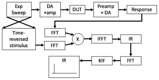
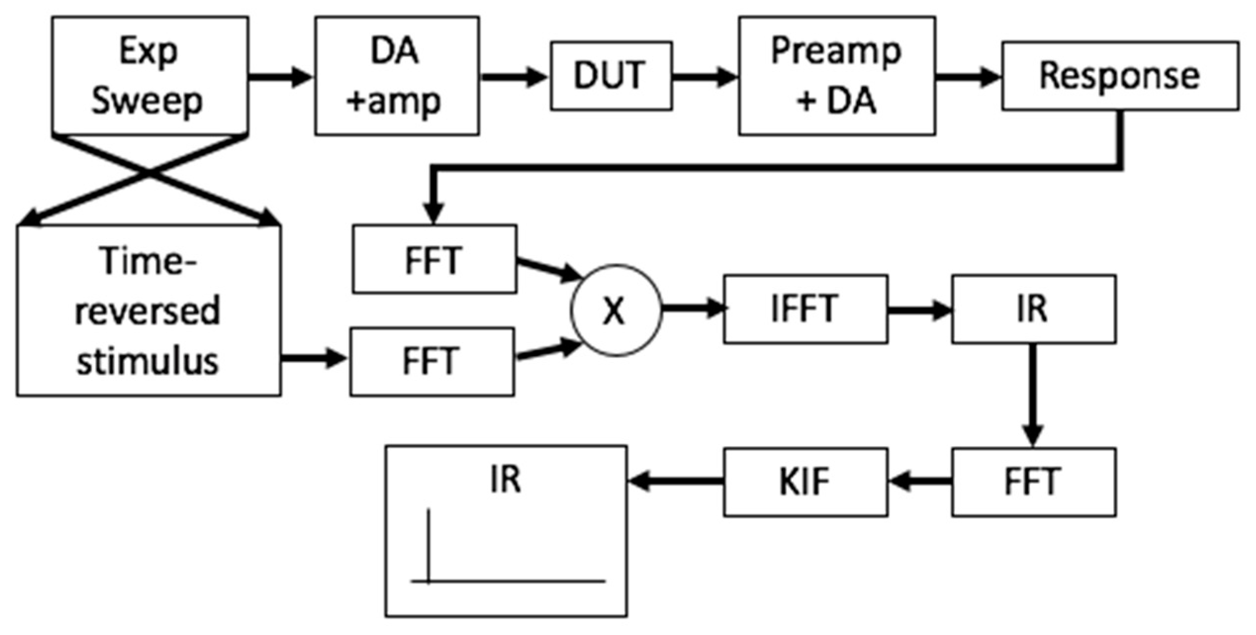
where and are the initial and end frequencies of the signal, respectively, and represents the time. In order to apply the deconvolution of the IR, is necessary to inverse the signal emitted. Figure 1 shows a general scheme of the process.
Figure 1.
Scheme of the impulse response measurement method where Exp Sweep is the exponential sweep, IR is impulse response, KIF is Kirkeby inverse filter, DA represents a digital amplifier, the FFT describe the Fourier transform and IFFT the inverse Fourier transform respectively, and X represents the multiply sign.
Once the signal has been emitted by the device under test (DUT) and recorded through a digital acquisition system (DAQ), the spectrums of the record signal and the inverse signal emitted are multiplied to get the impulse response. However, pre-riding at low frequencies due to a deficient sound card system, cause a high latency in the electromechanical loudspeaker transducer, as a consequence, there is a poor resolution in low frequencies. This effect can be corrected if the frequency-dependent latency remains the same, by creating a suitable inverse filter with the Kirkeby method (KIF) [4]. First, the signal IR to be inverted is FFT transformed to the frequency domain.
The filter is obtained in the frequency domain as a conjugated operation where is a small, frequency-dependent regularization parameter. Finally, an IFFT brings back the inverse filter to time domain.
2.2. Electromechanical Transducer Measurement
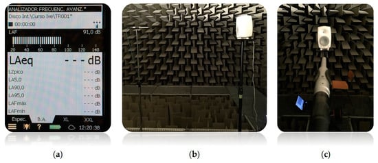
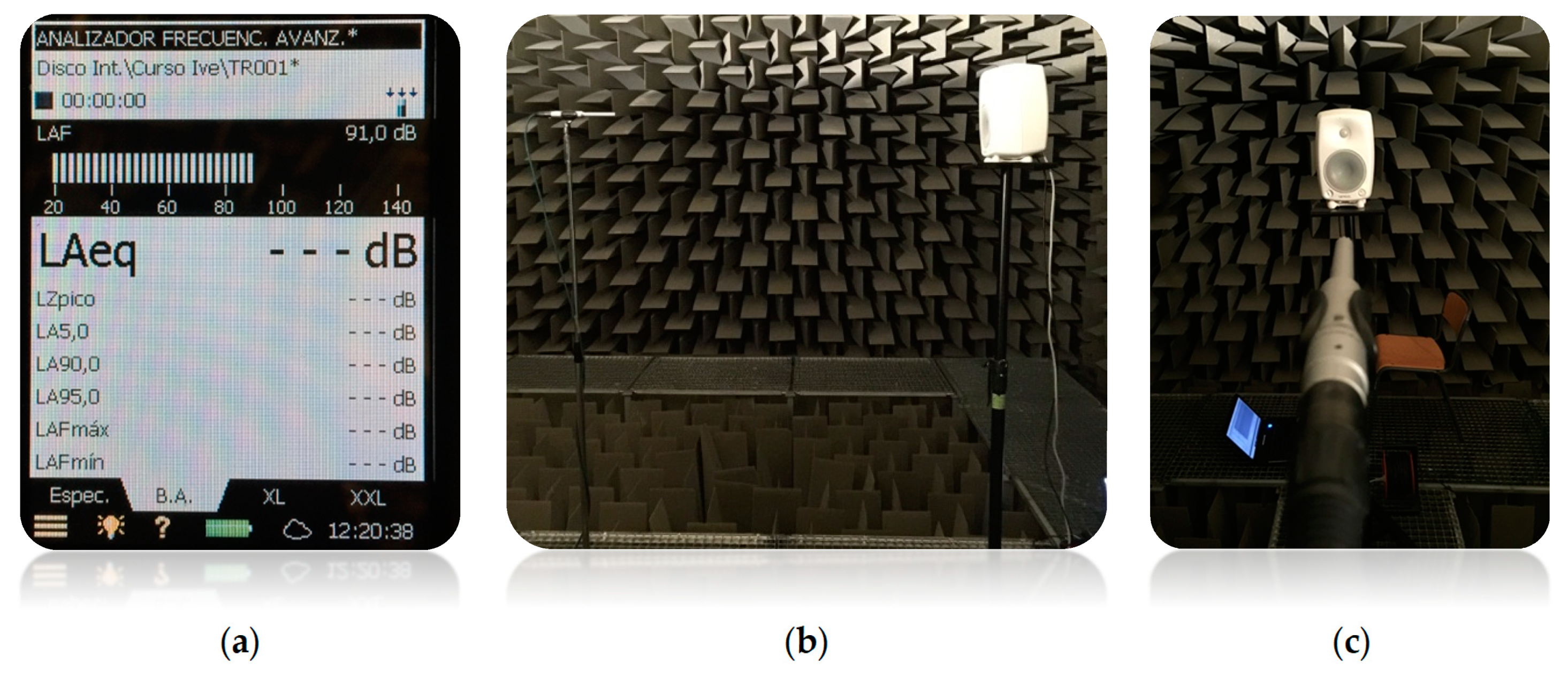
A sweep sinus measurement with a single microphone was performed. A Genelec 8010A loudspeaker was set up over a flat surface separated from the floor by 1.6 m. The receiver was a Behringer ECM 8000 microphone separated 1 m from the source. The set-up can be seen in Figure 2. The reflections in the medium due to the effect of the source in the walls, roof and floor, have been deleted due to the anechoic chamber.
Figure 2.
Set-up of the impulse measurement. (a) System calibration with white noise; (b) the transducer and receiver are in the middle of the anechoic chamber; (c) and the microphone is on the axis of the loudspeaker.
To emit and record the signal a laptop with Adobe Audition was prepared with the signal generated from to on an M-Audio sound card with . First, the signal was calibrated to with white noise as shown in Figure 2a, then the process of emitting and recording was repeated three times at the same length. Figure 3 shows the signal emitted and the signal recorded.
Figure 3.
Exponential sweep from to emitted and recorded.
The instantaneous sweep power should be controllable according to the frequency just being swept through. This can be accomplished by controlling the amplitude of the sweep in a frequency-dependent fashion, which is important because the signal could saturate the system, causing a non-linear operation on the membrane in its natural-resonance frequency.
2.3. Underwater Transducer Measurement
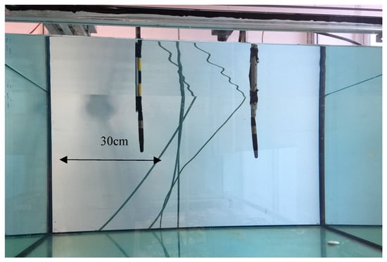
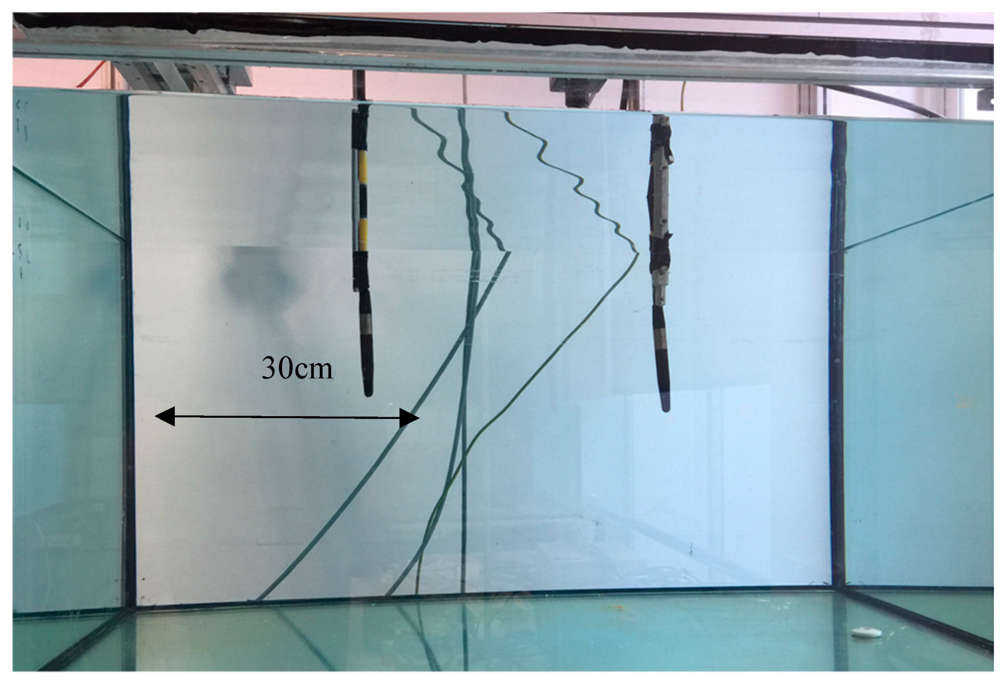
In order to evaluate the method, the process of impulse measurement was assessed in two RESON TC4034 transducers. The experimental environment was a water tank with a water volume of . Both similar sensors were separated from each other and a National Instruments DAQ was used with a sample rate of . Figure 4 shows the set-up of the experiment with both sensors.
Figure 4.
Set-up of the impulse measurement.
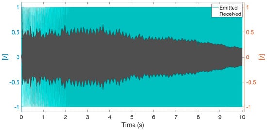
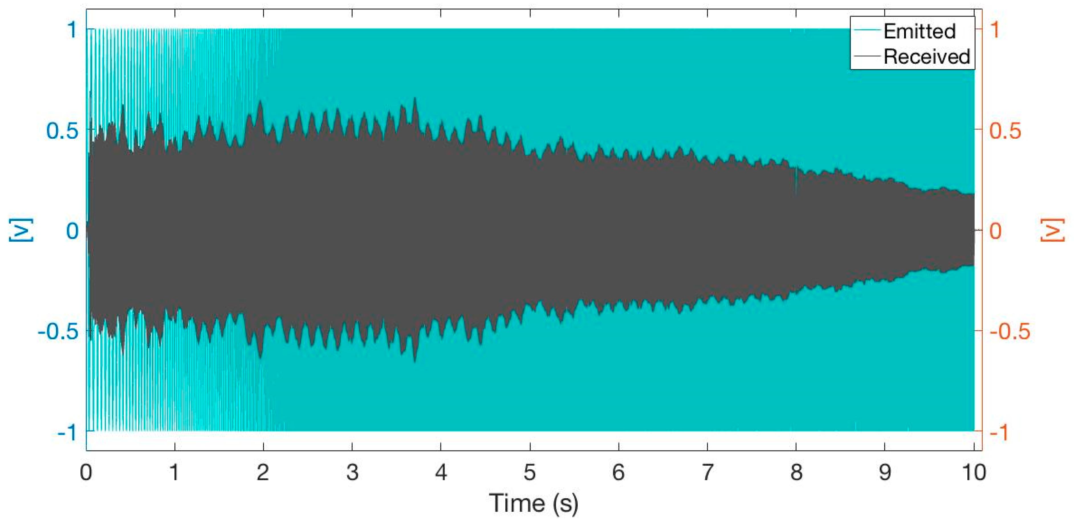
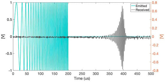
Due to the characteristics of the experimental space, the exponential sweep signal emitted had a duration of . This sweep was recorded for and in order to suppress all reflections, a time window of was used to extricate the direct signal from the file before the first scatter appeared and deleted the electromagnetic signal from the electric components. Figure 5 shows the characteristics of the emitted signal, and the maximum amplitude of the received signal where the resonance frequencies overlapped.
Figure 5.
Exponential sweep from to emitted and recorded.
The general idea of suppressing the first reflection with the sensor was to get the main signal from the transducer to the receiver on the axis direction. To do that, the cross-correlation method gave information about the time of arrival (TOA) [5], whereby there was the possibility to set the best fit to obtain only the direct signal and the time of the window to process the signal.
3. Results and Conclusions
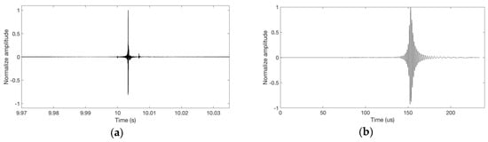
Impulse measurement of a mechanical and ultrasound transducer was obtained with the method described in this paper. This makes it possible to derive a general procedure for calculating these responses, which can be used for a different transducer. Figure 6 shows the que impulse response for the loudspeaker transducer and ultrasound transducer, respectively. With the exponential sweep technique, it is possible to simultaneously deconvolve the linear impulse response of the system and selectively separate each impulse response corresponding to the harmonic distortion orders considered. With this information, it is possible to determine, for example, the kind of signals that should be sent to each transducer when the signal expected is known.
Figure 6.
Impulse response of two systems analyzed. (a) IR of the loudspeaker in an anechoic environment; (b) Impulse response of underwater sensor in a reverberant environment.
The impulse response deconvolution process was realized by lineal convolution of the measured output with the analytical inverse filter processed from the excitation signal. Using lineal convolution allows time-aliasing problems to be avoided [6]. In fact, even if the time analysis window does not have the same length as the emitted signal, the tail of the system response may be lost, but this will not introduce time aliasing.
Experimental testing with a piezoelectric transducer showed that it was possible to suppress reflection from the given surface of the experiment and obtain good results in spite of the increase of the noise. In order to perform an objective comparison of the impulse response qualities, the optimal signal-to-noise ratios achievable for each transducer were compared. The signal-to-noise ratio definition used was the ratio expressed in dB between the average power of the signal recorded by the microphone and the average power of the noise present in the impulse response. In the case of the chamber room, the signal obviously had a better relation compared with the reverberant environment in the water tank. This assertion is confirmed by the results presented in Table 1.
Table 1.
Signal to noise ratio of the two different environments.
The good relationship of the signal-to-noise ratio of the exponential sweep method makes it a notable impulse response measurement technique in a lot of environments, provided the signal-to-noise ratio is enough to reduce que distortion in the IR and the time window is appropriately implemented.
Conflicts of Interest
The authors declare no conflict of interest.
References
- Kadlec, F. Impulse response measurement of ultrasonic transducers. Journal de Physique IV Colloque 1994, 4, 295–298. [Google Scholar] [CrossRef] [Scilit]
- Struck, C.J.; Temme, S.F. A Comparison of Techniques for Evaluation of Loudspeakers at Low Frequencies. In Proceedings of the Audio Engineering Society 95th Convention, New York, NY, USA, 7–10 October 1993. [Google Scholar]
- Muller, S. Transfer-Function Measurement with Sweeps. J. AES 2001, 49, 443–417. [Google Scholar]
- Farina, A. Advancements in impulse response measurements by sine sweep. In Proceedings of the 112nd AES Convention, Vienna, Austria, 5–8 May 2007. [Google Scholar]
- Gustafsson, F.; Gunnarsson, F. Positioning using time-difference of arrival measurements. In Proceedings of the IEEE International Conference on Acoutics, Speech, and Signal Processing, Hong Kong, China, 6–10 April 2003. [Google Scholar]
- Guy-Bart, S.; Jean-Jacques, E.; Dominique, A. Comparison of Different Impulse Response Measurement Techniques. J. AES 2002, 50, 249–262. [Google Scholar]

© 2018 by the authors. Licensee MDPI, Basel, Switzerland. This article is an open access article distributed under the terms and conditions of the Creative Commons Attribution (CC BY) license (https://creativecommons.org/licenses/by/4.0/).