


Abstract
This work points out a stability bifurcation which appears at low mass flow rates when simulating the flow inside of a compressor rotor alone, using the Body Force Modeling (BFM) approach with the Hall–Thollet formulation. This phenomenon is observed for a small propulsive axial fan, with and without model calibration. It does not have any consequence, since it happens far beyond the surge limit of the fan stage and involves “virtual” operating points which cannot be captured with blade simulations. However, this bifurcation also exists with centrifugal impellers, for which a flow recirculation usually takes place at low mass flow rates, enabling extension of the stable operating range. Thus, this represents a serious limitation of this method. This numerical behavior has not yet been documented in the BFM literature. Given the complexity of this subject and the number of parameters, the intention is not to carry out an exhaustive study here. But since the Hall–Thollet formulation is now quite commonly used in turbomachinery CFD, the objective of this work is to briefly report and describe the dichotomy in the solutions obtained.
1. Introduction
Body Force Modeling (BFM) is a low-fidelity approach which is classically used in turbomachinery simulations to capture first-order trends on complex configurations with limited CPU resources. It can successfully be applied to characterize the effects of flow distortion on propulsive or ventilation fans [1,2], multistage axial compressors [3], and propellers [4]. Thus, it is a relevant tool for modeling the interactions of a system with its close environment (nacelle, wing, S-duct), and its uses extend to multiphysics analysis (see [5], which deals with on aero-acoustics, for example), while maintaining a reasonable CPU cost.
Recent work involving six radial compressors lead to explore severe off-design operating conditions, showing that the BFM approach with this formulation satisfactorily captures the typical inlet recirculation which takes place at low mass flow rates [6]. However, a stability bifurcation is likely to happen in the range where the recirculation appears—depending on the initial conditions, two types of results can be obtained, involving different flow patterns and performance prediction. The same observation is made for a small propulsive axial fan, which suggests that the bifurcation can affect both axial and radial geometries. The objective of this work is to illustrate this phenomenon on different configurations and to propose a physical interpretation.
2. Body Force Modeling
Among through flow modeling techniques, many concepts coexist, with different pros and cons. The body force approach considered here is one of them. It relies on source terms to represent the effect of the blades on the flow. These source terms are expressed in the absolute frame (Equations (1)–(3)), which enables one to treat rotor–stator configurations with steady RANS simulations.
The baseline formulation of the Hall–Thollet model used here [7,8] is detailed in Appendix A.1. Since it is physics-based, it requires only geometric inputs, making it fully explicit and local. For this reason, it is also appreciated by industrial stakeholders, since performance-based calibrations can easily be implemented [9,10] (see Appendix A.2 for a typical procedure example).
This approach has already been tested with radial impellers [6] and demonstrated variable discrepancies compared to blade simulations when predicting pressure ratio and efficiency. The presence of inlet flow recirculation has been validated against experimental evidence through temperature measurements at the shroud endwall, which is already a satisfactory outcome without any model calibration.
However, an uncommon numerical behavior has also been reported at low mass flow rates, pointing out a stability bifurcation. Although performance maps are shown later in the present study, the values themselves are not relevant. Here, the aim is not to evaluate the fidelity or the accuracy of the BFM approach, but rather to qualitatively describe the flow inside the bifurcation range and give some physical insight of the BFM results.
3. Numerical Settings
All the simulations are carried out with StarCCM+ v17.06, a cell-centered finite volume solver developed by Siemens. In both axial and centrifugal cases, the computational domain includes a rotor alone. The source terms in the OGV area of the axial fan are deactivated.
The boundary conditions are identical for the axial case and the radial ones. A stagnation inlet is used, prescribing standard conditions for temperature and pressure ( = 288.15 K, = 101,325 Pa) and a turbulent viscosity ratio of 10. A mass flow condition is chosen at the outlet. No radial equilibrium is prescribed at the exit of the axial case. A periodicity condition is imposed on the azimuthal boundaries so that the flow is completely axisymmetric. All the walls are assumed to be adiabatic.
The standard one-equation Spalart–Allmaras turbulence model is chosen according to previous work which proved its ability to satisfactorily capture the flow structures inside of a centrifugal impeller with blade simulations [11].
Convective fluxes are calculated using a second-order upwind scheme. A second-order Runge–Kutta scheme is used for pseudo-time integration, with an automatic ramp-up concerning the Courant–Friedrichs–Lewy (CFL) number, which is linearly increased during the simulation.
Simulations are monitored using global quantities such as mass flow rate, total-to-total pressure ratio, and isentropic efficiency. As detailed in Section 4.1, some results with radial configurations exhibit periodic oscillations at convergence, suggesting that these operating points should be analyzed with an unsteady approach. This is out of the scope of this work and has not been explored in depth.
4. Stability Bifurcation at Low Mass Flow Rate
4.1. Centrifugal Impellers
For what concerns subsonic radial impellers, an upstream flow recirculation is likely to take place at low mass flow rates. This mechanism has a stabilizing effect and can lead to an enhancement of the impeller operating range, which explains that it is still a hot research topic (see [12] for a recent overview).
The results presented here come from a more global study [6], evaluating the ability of BFM to capture the correct flow topology, with special attention afforded to inlet flow recirculation. A stability bifurcation happens with six different impellers designed by Liebherr Aerospace Toulouse SAS, dedicated to various industrial applications. It has a notable impact on radial geometries, and the consequences vary from impeller to impeller. The following paragraphs give an overview of these results, without claiming to be exhaustive.
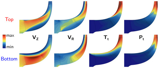
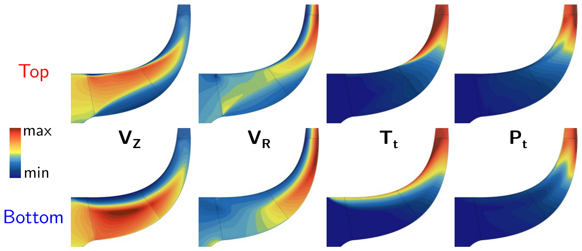
Inside the mass flow range where the BFM results bifurcate, the performance curves exhibit two distinct branches [6]. Figure 1 shows a typical flow field corresponding to the two solutions obtained in the bifurcation range with a splittered impeller, assuming the same mass flow is imposed. The results on the upper part correspond to the top branch (higher performance), and the others to the bottom branch (lower performance).
Figure 1.
Flow fields from both branches for the same mass flow condition: axial velocity, radial velocity, absolute stagnation temperature, and absolute stagnation pressure.
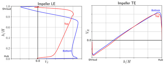
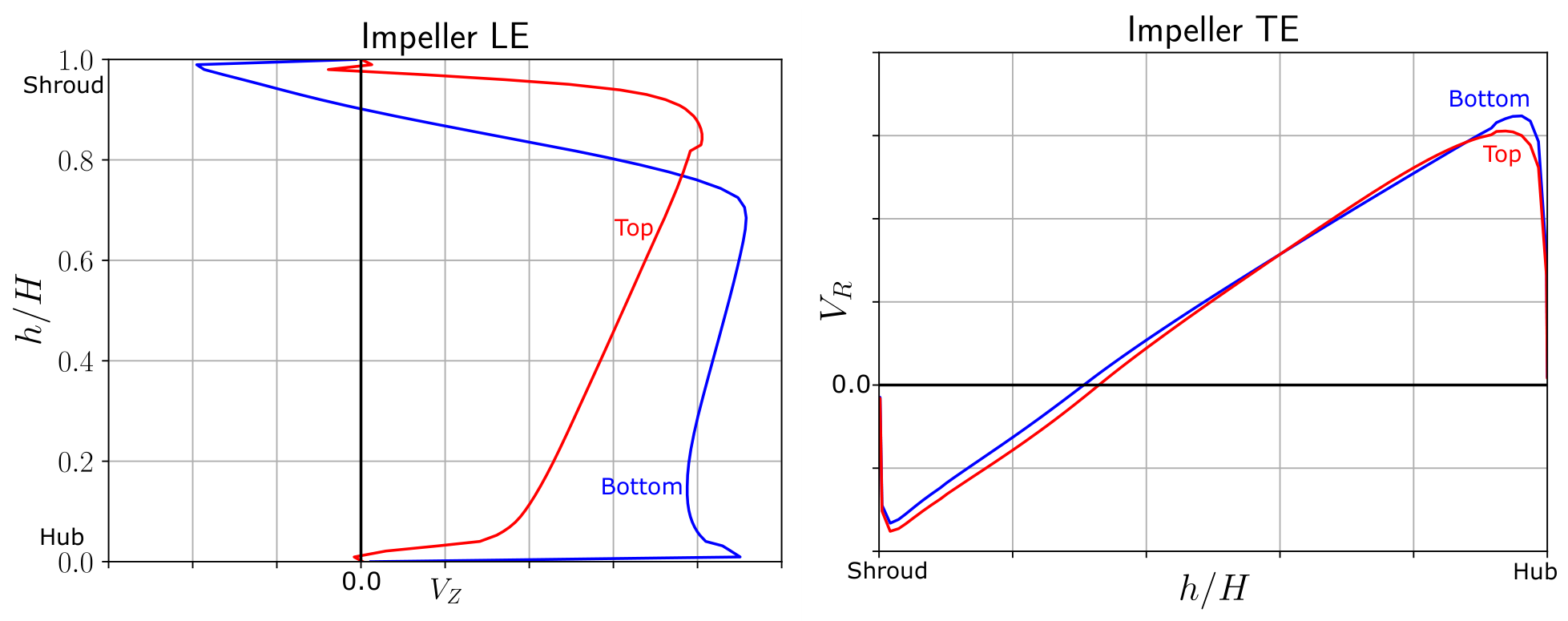
Interestingly, in the case of radial impellers, despite the very different spanwise profiles in the LE region of the main blade, the spanwise profiles in the TE region are nearly identical (Figure 2).
Figure 2.
Spanwise distributions of axial velocity in the main blade LE region and of radial velocity in the TE region.
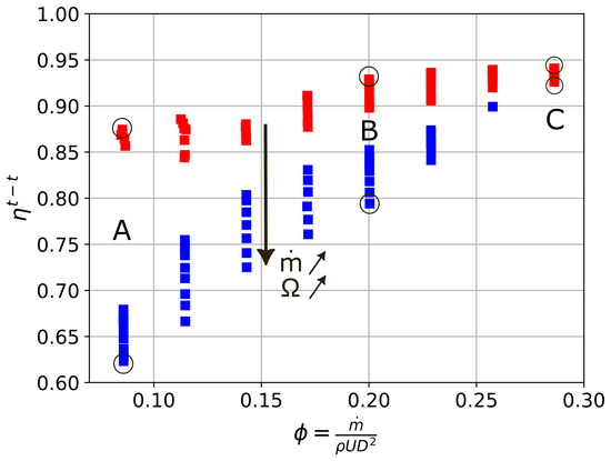
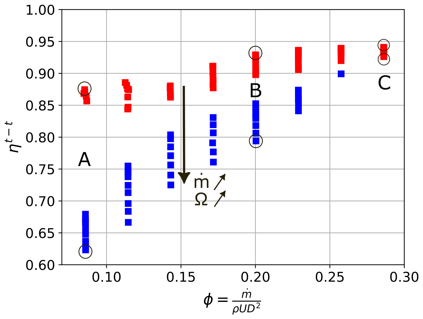
In order to obtain a bigger picture of the bifurcation, the low mass flow range has been explored for three of the six compressors, meaning we keep the same ratio for different mass flow coefficients. This systematic screening leads to the performance map shown in Figure 3. The total-to-total isentropic efficiency is the best indicator for discriminating the two types of flow behavior here.
Figure 3.
Isentropic efficiency for different (, ) combinations.
Two groups of points are obtained:
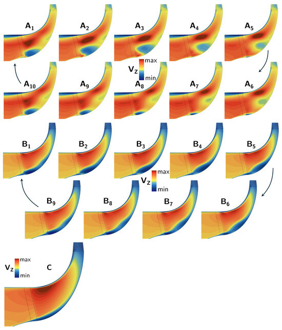
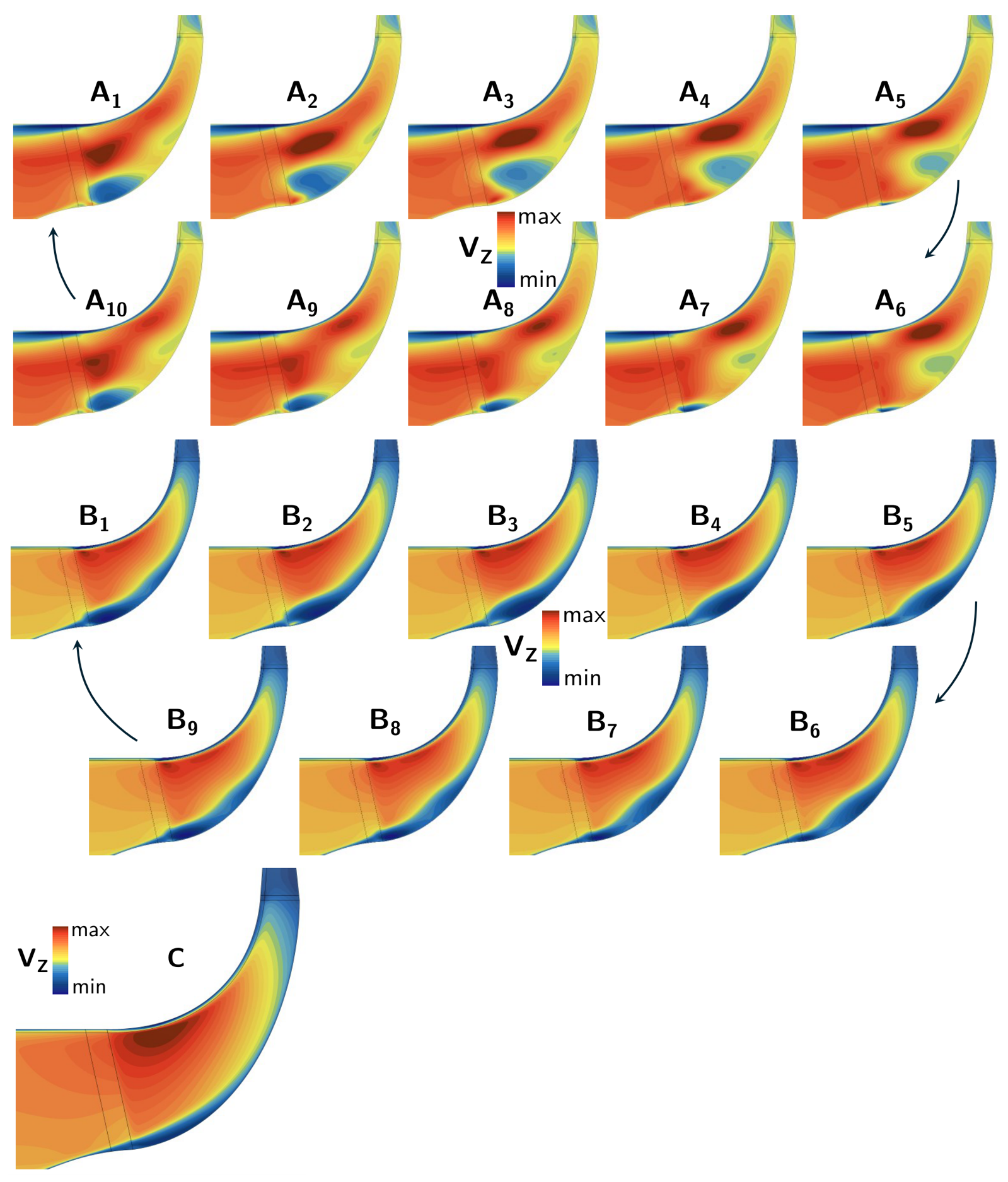
- The top group, in red, is associated with a hub separation (Figure 4). At high mass flow rates, this separation is small and steady. When the mass flow decreases, the separation bubble remains closed, but its size increases, and it starts oscillating. Finally, at low mass flow rates, this separation turns into a massive periodic vortex shedding which occupies a large part of the span and starts from the main blade LE. For a given value, these points are associated with low (, ) doublets;
- The bottom group, in blue, is associated with a shroud separation (Figure 5). It is steady and homogeneous on the whole mass flow range, progressively degenerating towards the expected inlet recirculation at the shroud. Once it is fully established at the main blade LE, its radial extension remains constant, and the separation point moves upstream in the axial direction when the mass flow decreases. For a given value, these points are associated with high (, ) doublets.
Figure 4.
Axial velocity field from the top branch for points A, B, and C.
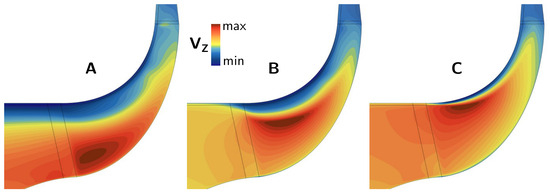
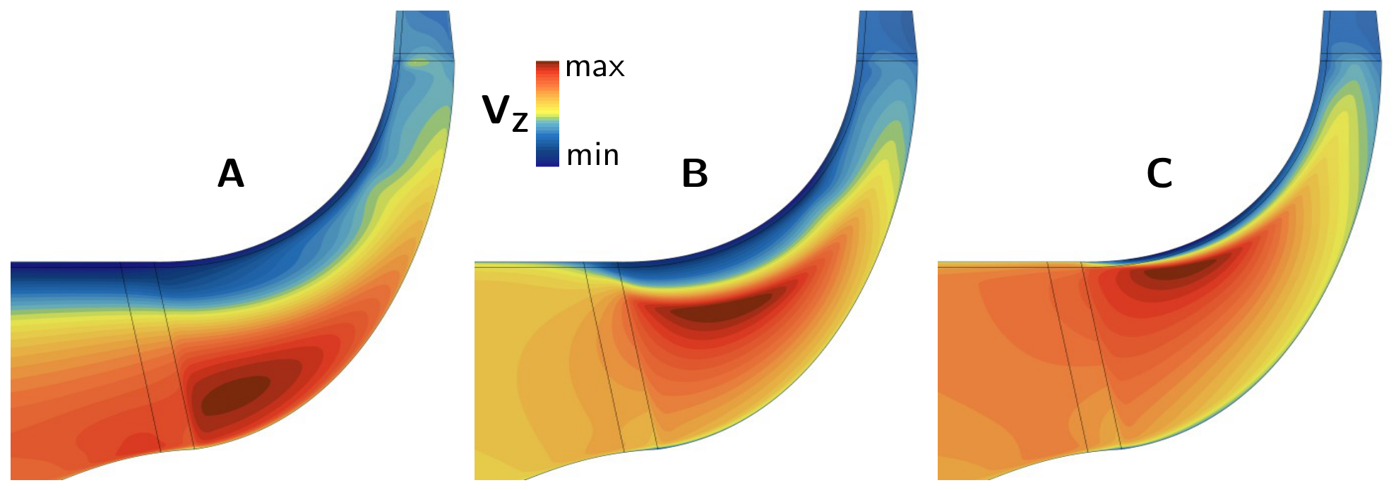
Figure 5.
Axial velocity field from the bottom branch for points A, B, and C.
The oscillations observed for low (, ) doublets suggest that no steady solution exists in this region and call for URANS simulations, which have not been undertaken. The concerned points have been discarded in the performance maps from [6] in order to avoid any overinterpretation, which explains empty operating ranges for some compressors.
A classical performance map based on constant rotational speedlines actually appears like a sampling of the more general one represented in Figure 3, in which discontinuities are due to the switch from one group to the another one. Depending on the initial conditions, two different paths can exist, from high to low mass flow rates and from low to high ones. Thus, in the transition range, the bifurcation draws a sort of hysteresis scheme (see [6]).
These results emphasize the need to explore (, ) values very far from the nominal ones to reveal the underlying physics. The presence of two separated branches associated with different flow patterns involving the opposite endwalls shows some similarity with the typical flow behaviors inside of diffusers (see [13], for example). Indeed, depending on the equivalent diffusion angle, different flow patterns can be observed, steady or unsteady, among which some can be bistable. However, this analogy is limited for at least three reasons:
- The area ratio across the impellers is always inferior to 1 because of their meridional shape.
- Due to the source terms of Equation (3), the flow inside the bladed area receives an amount of work which changes for each operating point.
- The geometry is axisymmetric by definition, with a rotating wall at the hub, which introduces additional effects.
Moreover, although the mechanisms involved in the bifurcation seem the same, the fact that the force field imposed in the present formulation is local makes their combination complex and slightly different for each impeller investigated. For now, the generalizability of these findings remains an open question.
4.2. Axial Propulsive Fan
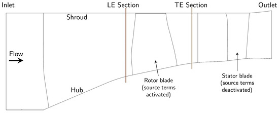
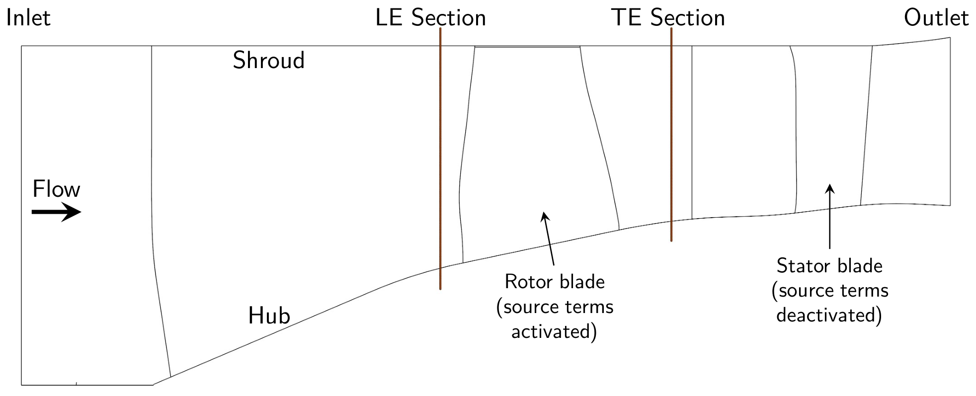
The axial test case considered concerns the fan rotor of the DGEN 380, a geared turbofan developed by Price Induction, now Akira, designed for a cruise altitude of 4500 m and a flight Mach number of 0.338. The performance maps of this fan stage, obtained via CFD, are available at nominal operating conditions, as well as at windmill [14]. The performance results of the fan rotor are post-processed between the LE and the TE sections defined in Figure 6.
Figure 6.
Meridional schematic of the BFM computational domain.
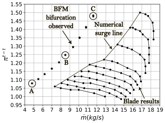
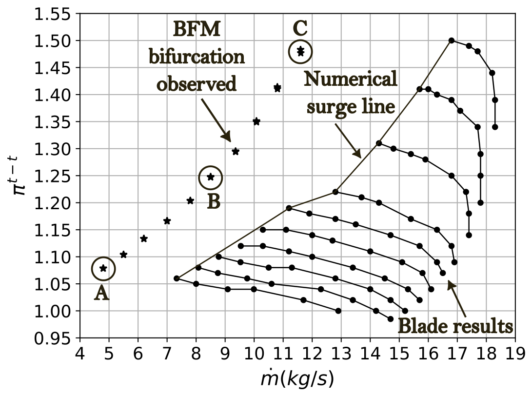
Figure 7 shows a performance map obtained with blade simulations for different rotational speeds. Considering the blade results as the numerical reference, this section focuses on “virtual” operating points which satisfactorily converge with BFM simulations but which are located far beyond the surge limit. Here, the baseline formulation of and introduced in Appendix A.1 is directly applied without any calibration.
Figure 7.
Total-to-total pressure ratio map of the fan rotor: blade results for different rotational speeds and BFM bifurcation points.
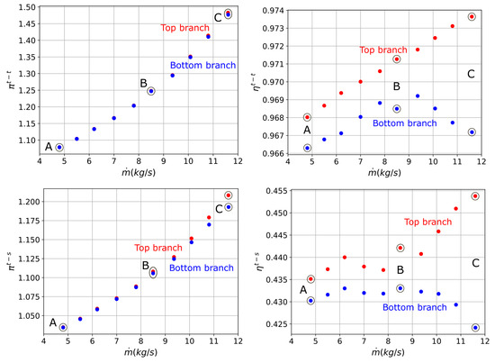
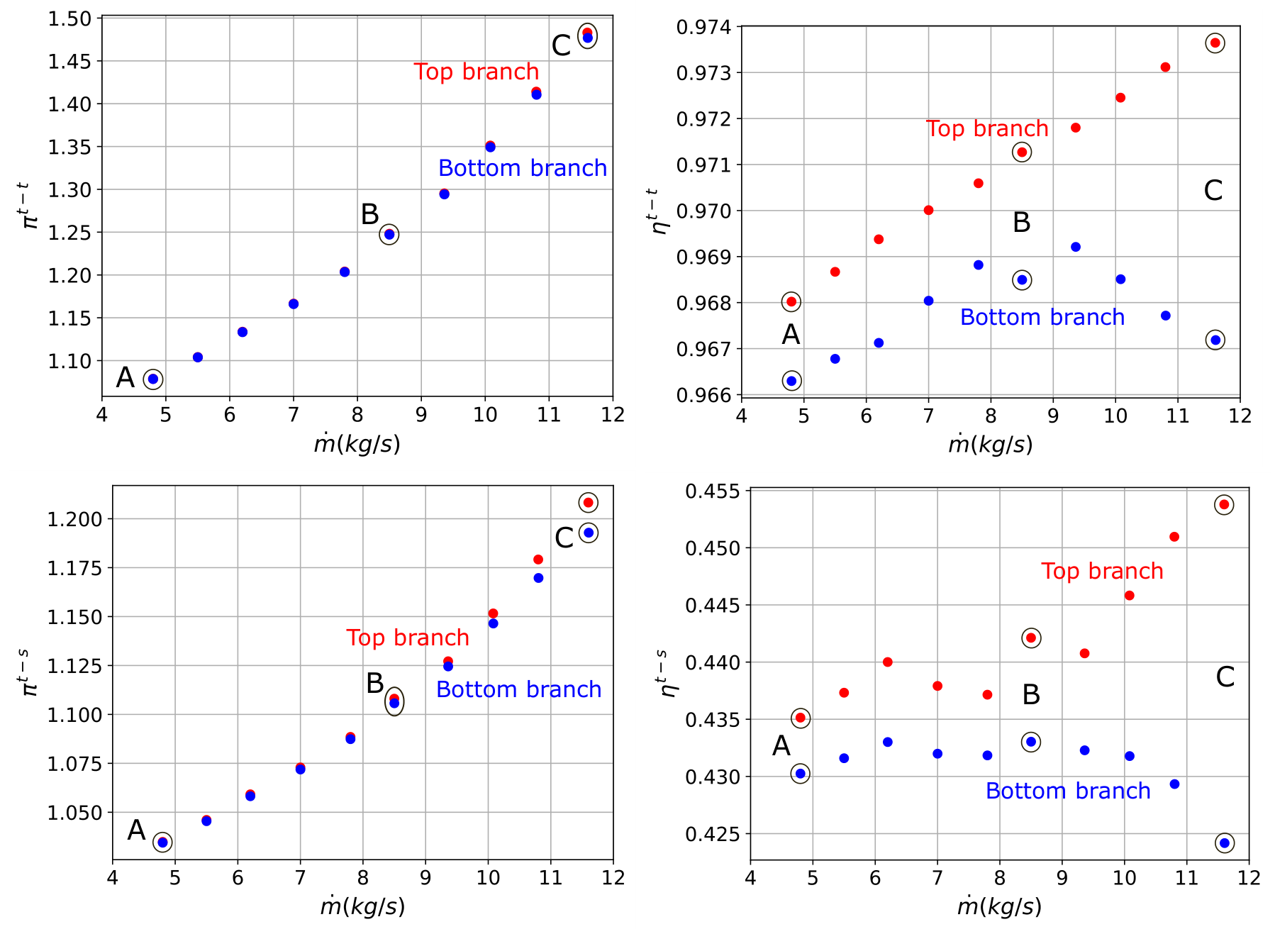
The doublets in Figure 8 approximately correspond to the same mass flow coefficient, namely the same ratio. Although the impact of the stability bifurcation on the performance is much lower than in Section 4.1, the total-to-total and total-to-static efficiencies clearly show the same two groups of points: a top branch in red (higher values) and a bottom branch in blue (lower values). A simple offset separates them for low (, ) doublets, whereas the two branches move away from each other for high (, ) doublets.
Figure 8.
Performance maps of the fan rotor predicted by BFM simulations in the bifurcation area: total-to-total and total-to-static pressure ratio and isentropic efficiency.
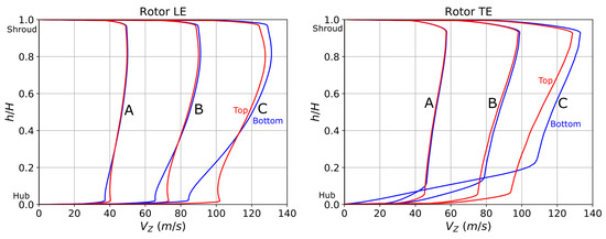
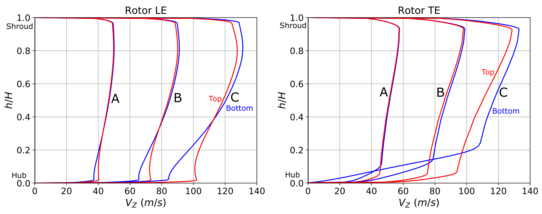
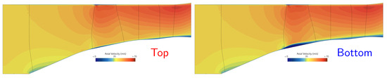
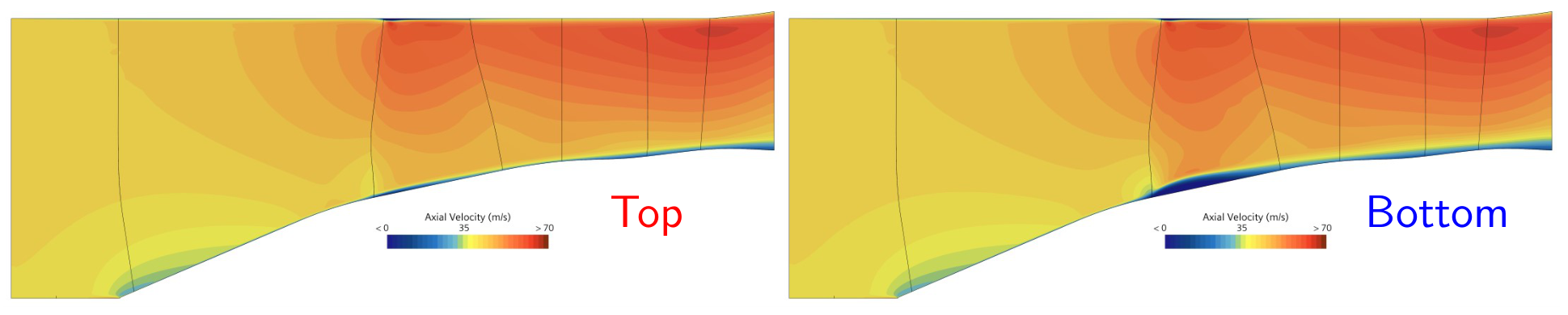
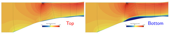
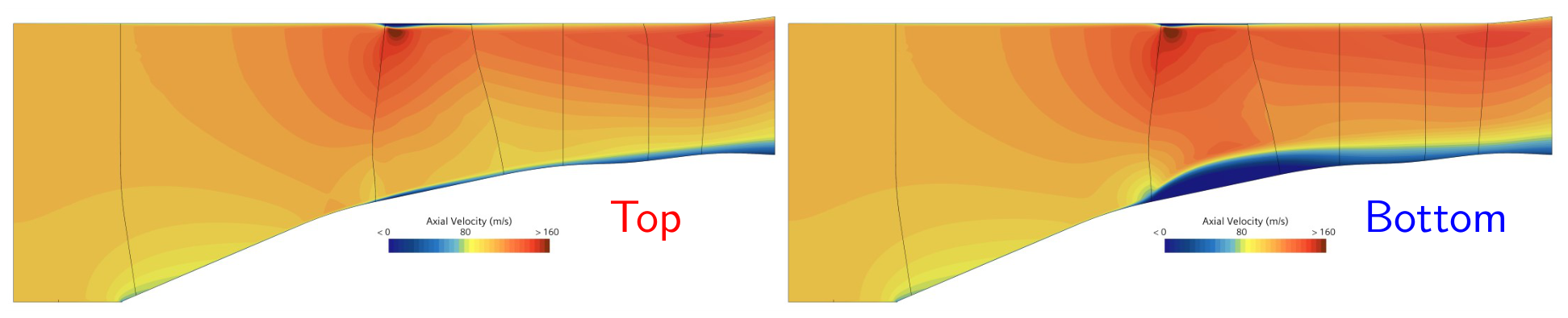
Figure 9 shows the radial profiles of axial velocity in the LE and TE sections, associated with three different operating points—A, B, and C (see Figure 8)—for both branches. Contrary to radial impellers, the exit profiles are easy to distinguish. For a given mass flow coefficient, the more and increase, the wider the gap becomes. The difference comes from the flow separation taking place at the hub inside the bladed area of the bottom branch, as illustrated in Figure 10 and Figure 11.
Figure 9.
Spanwise distributions of axial velocity in the LE and TE regions of the fan rotor.
Figure 10.
Axial velocity fields for point A.
Figure 11.
Axial velocity fields for point C.
For both axial and centrifugal compressors, the velocity distribution in the LE region is an interesting basis for building a shape factor which could be used as a quantitative indicator and to help discriminate the two branches. This point is not investigated in the present work.
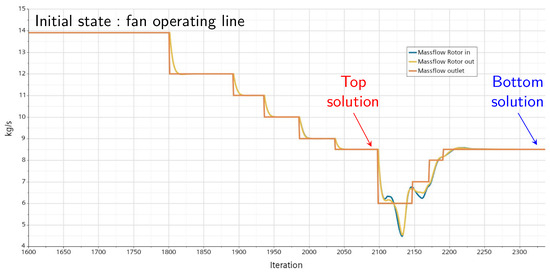
Figure 12 illustrates the influence of the numerical transient. Depending on the initial conditions, two possible results are obtained, leading to the two branches described. The same convergence criteria are reached in both cases.
Figure 12.
Influence of the initial conditions for point B: mass flow convergence history.
BFM simulations performed with a calibrated version of the same test case (see Appendix A.2) yielded the exact same behavior. This work has not been pursued further because the involved operating points are of little interest for this fan, as they will never be seen in real life. However, from a methodological point of view, this limit remains problematic when the same approach is applied to low mass flow conditions which can really be reached, as with centrifugal impellers in Section 4.1.
4.3. Current Limitations
The same type of bifurcation is observed for axial and centrifugal compressor rotors. However, it cannot yet be unambiguously identified as a physical phenomenon rather than a modeling or numerical artifact related to the Hall–Thollet BFM formulation. This study has been performed with a given numerical framework, relying on steady RANS assumptions and imposing particular boundary conditions and initial conditions.
It should be emphasized that URANS simulations in the bifurcation range were not performed, although it would be possible (see [15] for an example of unsteady BFM simulations applied to compressor stall). For that reason, oscillatory points were discarded, and the physical interpretation of the two branches therefore remains tentative.
For centrifugal impellers, more details from blade-resolved comparisons are reported in [6] but remain partial. Steady blade simulations also happen to exhibit oscillations depending on the compressor, hence empty operating ranges for blade simulations too. A measurement campaign is still ongoing at ISAE-SUPAERO and will be used for comparison with numerical results, especially in the recirculation onset region but experimental data are not available yet. Given the current lack of validation, sensitivity studies and alternative BFM formulations remain necessary future work.
5. Conclusions and Perspectives
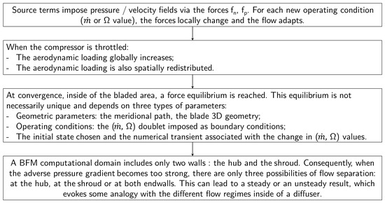
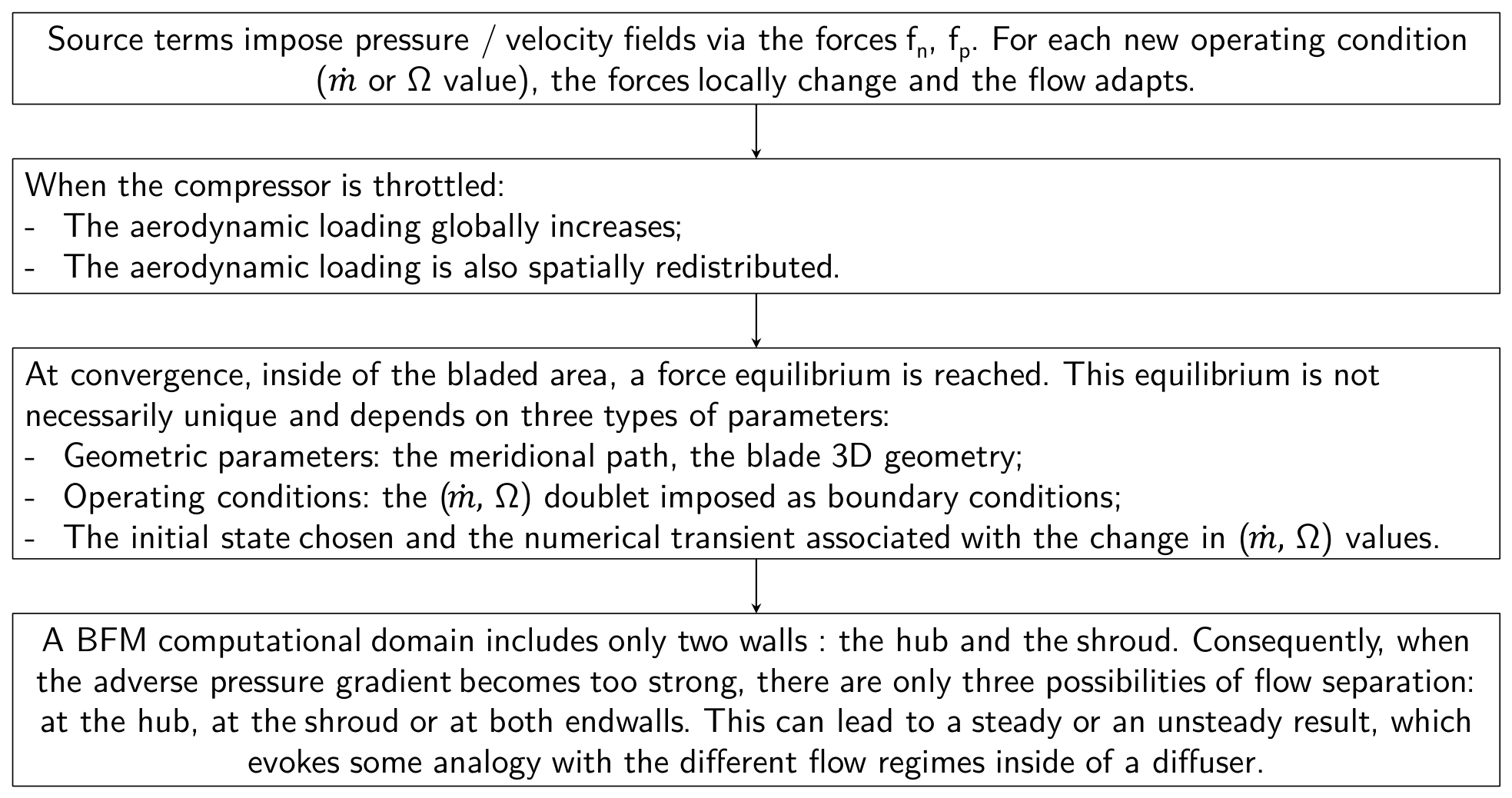
Figure 13 gives an overview about the stability bifurcations observed in both radial and axial rotors via BFM simulations. This interpretation should ideally be completed and corrected by other cases from the BFM community.
Figure 13.
Interpretation proposed for the stability bifurcation observed with BFM simulations at low mass flow rates.
This work raises new questions about the current formulation:
- Does the bifurcation exist with other models, such as Gong’s one [16]? Is it generic due to BFM or only due to the Hall–Thollet formulation?
- The instability observed at low mass flow rates looks similar to the one with axial inducers reported by Sorensen [17], who added a bi-normal force in the equations. How should the modeling be enriched?
- The global behavior seems unchanged when the forces are calibrated at the nominal operating conditions. Is there another way to proceed in order to eliminate the stability bifurcation and ensure the right flow recirculation for centrifugal impellers at low mass flow rates?
Depending on each configuration, the bifurcation is not always visible. It currently represents a limit to the BFM approach which probably has no consequence with axial compressors but can be an obstacle with radial impellers, especially when special attention is drawn to the prediction of inlet flow recirculation at low mass flow rates.
Author Contributions
Methodology, G.D.; investigation, E.B., N.P., V.C. and X.F.; supervision, V.C. and N.B.; project administration, V.C., Y.B. and N.B. All authors have read and agreed to the published version of the manuscript.
Funding
This research was funded in part by the Agence Nationale de la Recherche (ANR), grant ANR-23-CHIN-0004. Computer and storage resources were provided by GENCI at CINES and TGCC thanks to the grant 2025-A0172A06879, focused on GENOA and ROME partitions of the supercomputers Adastra and Joliot Curie.
Data Availability Statement
The datasets presented in this article are not readily available because due to technical/time limitations.
Acknowledgments
The authors are grateful to Liebherr Aerospace Toulouse SAS for providing the impeller geometries and for supporting this study, which is part of the joint research initiative between CASTOR and ISAE-SUPAERO.
Conflicts of Interest
Authors Nicolas Poujol, Viviane Ciais, and Xavier Flete were employed by the company Liebherr. The remaining authors declare that the research was conducted in the absence of any commercial or financial relationships that could be construed as a potential conflict of interest.
Abbreviations
The following abbreviations are used in this manuscript:
| BFM | Body Force Modeling |
| LE | Leading Edge |
| TE | Trailing Edge |
| RANS | Reynolds-Averaged Navier–Stokes |
Symbols
The following symbols are used in this manuscript:
| b | Metal blockage coefficient |
| Flat plate turbulent friction coefficient | |
| d | Curvilinear distance to the blade LE |
| f | Body force per unit mass |
| Compressibility correction | |
| Calibration coefficients | |
| M | Relative Mach number |
| Mass flow | |
| N | Rotor blade number |
| Blade camberline normal vector | |
| P | Pressure |
| R | Radius |
| Cylindrical coordinates | |
| Local Reynolds number | |
| s | Rotor blade pitch |
| T | Temperature |
| W | Relative velocity |
| Local deviation angle | |
| Isentropic efficiency | |
| Dynamic viscosity | |
| Pressure ratio | |
| Density | |
| Mass flow coefficient | |
| Angular rotationnal speed |
Subscripts and Exponents
The following symbols are used in this manuscript:
| n | Normal to the flow |
| p | Parallel to the flow |
| t | Stagnation quantity |
| Total-to-total | |
| Total-to-static |
Appendix A
Appendix A.1. Hall–Thollet Baseline Formulation
The usual BFM decomposition relies on a normal-to-the-flow force, , responsible for the turning, and a parallel force, , accounting for the losses. They are calculated using Equations (A1)–(A7). Source terms are deactivated in the tip gap regions but no additional loss is imposed there. M is the local relative Mach number, the local 3D deviation angle. d is the curvilinear distance to the blade leading edge on which the local Reynolds number is based to evaluate the friction coefficient . The metal blockage b is equal to 1 outside of the bladed area.
Appendix A.2. Calibration Used with the Axial Case
The performance of the DGEN fan rotor have also been calibrated taking the results from blade simulations as reference. Tuning coefficients are added to Equations (A6) and (A7) to modify the shape of the pressure ratio and efficiency curves by using Equations (A8) and (A9) instead.
The calibration procedure consists in the following steps:
- Considering only the pressure ratio, the value of is varied until the BFM curve is tangent to the blade curve.
- The flow deviation 2D field is extracted from the BFM result at the tangency point.
- Considering only the isentropic efficiency, the values of , and are adjusted in order to make the BFM results match the blade results for three operating points: the tangency point, the minimum mass flow rate, and the maximum mass flow rate.
- , and are finally defined as two-part linear functions from the three triplets previously found.
References
- Thollet, W.; Dufour, G.; Carbonneau, X.; Blanc, F. Body-force modeling for aerodynamic analysis of air intake–fan interactions. Int. J. Numer. Methods Heat Fluid Flow 2016, 26, 2048–2065. [Google Scholar] [CrossRef] [Scilit]
- Benichou, E.; Dufour, G.; Bousquet, Y.; Binder, N.; Ortolan, A.; Carbonneau, X. Body force modeling of the aerodynamics of a low-speed fan under distorted inflow. Int. J. Turbomach. Propuls. Power 2019, 4, 29. [Google Scholar] [CrossRef] [Scilit]
- Crea, C.; Marty, J.; Barrier, R.; Cochon, S.; Dufour, G. Body Force Modelling of a Multi-Stage High-Pressure Compressor Under Inlet Distortion. Int. J. Turbomach. Propuls. Power 2025, 10, 12. [Google Scholar] [CrossRef] [Scilit]
- Kiffer, T.; Dufour, G.; Gojon, R.; Thollet, W.; López de Vega, L. Extension and validation of the Body Force Method to a propeller blade. In Proceedings of the AIAA AVIATION 2023 Forum, San Diego, CA, USA, 12–16 June 2023; p. 3378. [Google Scholar]
- Defoe, J.; Narkaj, A.; Spakovszky, Z. A body-force based methodology for predicting multiple-pure-tone noise: Validation. In Proceedings of the 16th AIAA/CEAS Aeroacoustics Conference, Stockholm, Sweden, 7–9 June 2010; p. 3747. [Google Scholar]
- Benichou, E.; Binder, N.; Dufour, G.; Bousquet, Y.; Poujol, N.; Ciais, V.; Flete, X. Prediction of Inlet Recirculation for Centrifugal Impellers with Body Force Modeling. Aerosp. Sci. Technol. 2026, 175, 111862. [Google Scholar] [CrossRef] [Scilit]
- Hall, D.K. Analysis of Civil Aircraft Propulsors with Boundary Layer Ingestion. Ph.D. Thesis, Massachusetts Institute of Technology, Cambridge, MA, USA, 2015. [Google Scholar]
- Thollet, W. Body Force Modeling of Fan-Airframe Interactions. Ph.D. Thesis, ISAE-SUPAERO Toulouse, Toulouse, France, 2017. [Google Scholar]
- Kim, H.; Liou, M.S. Flow simulation and optimal shape design of N3-X hybrid wing body configuration using a body force method. Aerosp. Sci. Technol. 2017, 71, 661–674. [Google Scholar] [CrossRef] [Scilit]
- Hill, D.J.; Defoe, J.J. Innovations in body force modeling of transonic compressor blade rows. Int. J. Rotating Mach. 2018, 2018, 6398501. [Google Scholar] [CrossRef] [Scilit]
- Dufour, G.; Cazalbou, J.B.; Carbonneau, X.; Chassaing, P. Assessing Rotation/Curvature Corrections to Eddy-Viscosity Models in the Calculations of Centrifugal-Compressor Flows. J. Fluids Eng. 2008, 130, 091401. [Google Scholar] [CrossRef] [Scilit]
- Ullah, T.; Sobczak, K.; Liskiewicz, G.; Mucha, M. Numerical Investigations of Inlet Recirculation in a Turbocharger Centrifugal Compressor. Energies 2025, 18, 903. [Google Scholar] [CrossRef] [Scilit]
- Fox, R.W.; Kline, S. Flow regimes in curved subsonic diffusers. J. Fluids Eng. 1962, 84, 303–312. [Google Scholar] [CrossRef] [Scilit]
- Dufour, G.; Thollet, W. Body Force Modeling of the Aerodynamics of the Fan of a Turbofan at Windmill. In Proceedings of the ASME Turbo Expo 2016: Turbomachinery Technical Conference and Exposition, Seoul, Republic of Korea, 13–17 June 2016; American Society of Mechanical Engineers: New York, NY, USA, 2016; Volume 49712, p. V02CT39A045. [Google Scholar]
- Awes, A.; Dufour, G.; Daon, R.; Marty, J.; Barrier, R.; Carbonneau, X. Unsteady body force methodology for fan operability assessment under clean and distorted inflow conditions. In Proceedings of the AIAA Scitech 2021 Forum, Virtual Event, 11–15 January 2021; p. 0388. [Google Scholar]
- Gong, Y.; Tan, C.; Gordon, K.; Greitzer, E. A computational model for short-wavelength stall inception and development in multistage compressors. J. Turbomach. 1999, 121, 726–734. [Google Scholar] [CrossRef] [Scilit]
- Sorensen, W.A. A Body Force Model for Cavitating Inducers in Rocket Engine Turbopumps. Ph.D. Thesis, Massachusetts Institute of Technology, Cambridge, MA, USA, 2014. [Google Scholar]
Disclaimer/Publisher’s Note: The statements, opinions and data contained in all publications are solely those of the individual author(s) and contributor(s) and not of MDPI and/or the editor(s). MDPI and/or the editor(s) disclaim responsibility for any injury to people or property resulting from any ideas, methods, instructions or products referred to in the content. |
© 2026 by the authors. Published by MDPI on behalf of the EUROTURBO. Licensee MDPI, Basel, Switzerland. This article is an open access article distributed under the terms and conditions of the Creative Commons Attribution (CC BY-NC-ND) license.