


Abstract
In the present work, the incorporation of Nb in the volume of weld seams during electron beam welding of Al6082-T6 plates was investigated. The Nb was introduced into the weld seam in the form of a direct current (DC) magnetron-sputtered filler. The experiments were conducted with different technical parameters where the power of the heat source was constant, but the geometry of the oscillation of the electron beam was varied. In the first case, circular oscillation was used with a radius rosc = 0.2 mm, and in the second case, elliptical beam oscillation was used with a length l = 2 mm and a width d = 0.2 mm. The structure of the samples and some mechanical properties were investigated. A mathematical model was prepared, and the obtained results were comparable to the experimentally obtained ones. Using circular oscillation, poor miscibility of the aluminum and niobium, poor melting of the Nb filler, and a high concentration of defects were observed. No intermetallic compounds (IMCs) were detected in this case. In the case of applying elliptical beam oscillation, excellent miscibility between aluminum and niobium was achieved, and a homogeneous spread of Al3Nb intermetallics along the entire volume of the weld seam was achieved. This increased the density of the joint by minimizing the formation of defects, such as solidification pores, and by decreasing the size of the secondary phase particles within the weld seam from 33.11–61.41 µm to 3.63–7.75 µm. This resulted in an increase in the mechanical properties, with the average hardness of the fusion zone going from 72.6 ± 3.3 HV to 83.4 ± 3.5 HV and the average tensile strength going from 225 ± 8 MPa to 275 ± 8 MPa.
1. Introduction
In practice, it is common to form metallic components and join them together in order to form much larger structures. Joints between metallic parts can be made either detachable or non-detachable. Detachable ones usually employ the use of fasteners or quick release mechanisms [1], while non-detachable ones usually employ the use of high-energy sources in order to conjoin the components together. A prominent method for doing so is welding. There are a vast number of welding techniques made suitable (in some cases made specifically) for joining metals and alloys such as shielded metal arc welding (SMAW), gas metal arc welding (GMAW), gas tungsten arc welding (GTAW), laser beam welding (LBW), electron beam welding (EBW), friction stir welding (FSW), and more [2]. Typically, aluminum and its alloys are welded using GTAW due to the very high precision of this method and the excellent heat distribution [3]. This is unsurprising since gas tungsten arc welding was designed around the mid-20th century specifically for welding thin lightweight metals and alloys such as aluminum, magnesium, and titanium-based ones. This was necessitated by two factors. Firstly, a known problem with those materials was the high thermal instability and the necessity of precise control of the electric arc and thus the formation of a stable melt pool. Additionally, previous methods typically used either carbon electrodes or oxide-based coatings. However, with these materials, conventional (at the time) techniques and methods resulted either in the formation of cracks or porosity due to the incorporation of impurities in the weld seams. For this, gas tungsten arc welding found great application, and even to this day it remains one of the main methods for welding and joining metals and alloys. Shortly after GTAW was invented, other highly promising methods for welding were created, such as laser beam welding and electron beam welding. However, due to the very high thermal density of the electron beam, it was primarily used for the welding of either large components or ones made of refractory metals [4]. However, the high-vacuum environment and the high controllability (even potential for full automation of the process) make EBW very interesting for industrial fields that work with lightweight materials, which are not only heat-sensitive, but are also sensitive to gas incorporation into their structure and the formation of gas-related defects during welding, such as pores and cracks. This is mitigated by the implemented high-vacuum environment [5]. Furthermore, electron beam welding is characterized by very small heat-affected zones compared to other welding processes [6]. This makes it possible to form welds near materials with exceptionally low thermal resistance.
Despite all the great merits of electron beam welding, the technology has a monumental drawback related to its very high thermal density. Exactly due to this feature of the process, very high cooling speeds are observed in the weld seam [7]. This generates a lot of internal stresses within the materials and weakens the structure of the weld seam by forming defects such as pores or cracks, which often leads to either a sizeable reduction in the mechanical properties or a complete failure of the joints altogether. Multiple ways to reduce internal strains during electron beam welding have been introduced, such as preheating the samples before inserting them into the EBW unit [8], or preheating them by using the electron beam itself immediately before the welding process occurs, such as in the case of Weglowski et al. [4]. Another highly investigated method in practice is the addition of an intermediate layer between the welded pieces made of an entirely different material. This fundamentally changes not only the transfer of heat, thus the heating and cooling rates, but also makes it possible to form intermetallic compounds. The latter can also form by welding dissimilar metals and alloys; however, this typically happens uncontrollably—the mixture is poor and unevenly distributed in the weld seam and can cause the weakening of the joints and even their complete failure [9]. This is why inserting an intermediate metal between the weld pieces has to be accompanied by selecting the right (optimal) technological conditions necessary for the successful integration of the intermediate metal into the structure of the weld seam in a controllable, desirable fashion. This guarantees that the output mechanical properties of the formed welds will not be decreased and might be increased.
Aluminum and its alloys have proven to be some of the most prominent materials used in modern industries to make all types of components—from large structures such as planes and scaffolding to tiny electrodes used in microelectronics [10]. The high interest in this material is derived from its excellent properties such as good corrosion resistance, light weight, high thermal and electrical conductivities, high mechanical strength, easy alloying, excellent formability and treatability, and more [10]. An additional merit of using aluminum and its alloys is their excellent recyclability and reprocessing [11]. A well-known problem with aluminum and its alloys is that a large quantity of pores and cracks forms during processes involving high thermal gradients, and thus high solidification speeds, such as laser and electron beam welding [12]. This is attributed to the high coefficient of thermal expansion of the base aluminum matrix [13]. This is a prominent issue that is still an ongoing topic of investigation within the scientific community, since defects and internal stresses are one of the most common reasons for joint failure.
A possible solution to this issue is the application of a filler that can be incorporated into the weld seam. It can alter the physical processes that occur during welding, which in turn would also alter the resultant structure and potentially increase the mechanical properties. A typical filler used for laser and electron beam welding is AlSi18, with an average Si content of 18%, as proven by Gatzen et al. [14]. Al-Si-based filler wires were also proven viable for electron beam welding of pure aluminum and 304 stainless steel by Wang et al. [15]. Other typical filler materials used in practice are Al-Cu- and Al-Mg-based fillers [16]. In other instances, copper has been used in order to improve fusion in the molten zone, improve the structure of the weld seams, and also increase strength [17]. Although positive results in the field of laser and electron beam welding of aluminum alloys with different fillers have been achieved, further improvement of the structure is required in order to improve joint strength even more.
Niobium (Nb) is a highly promising material that can be used as an intermediate layer (filler) when attempting to weld aluminum components using electron beam welding. This assumption was made due to the excellent chemical bonds that form between aluminum and niobium. These bonds can be in the form of binary compounds of the architecture NbxAly [18] or ternary compounds when different materials are used, such as Ti, which is highly popular [19]. These intermetallic compounds have vastly different properties compared to the base materials, such as high hardness, low thermal conductivity, high density, high strength, low ductility, poor fracture toughness, and more [18,19,20]. Typically, the presence of intermetallic compounds in the weld seam leads to brittleness of the joints and the formation of defects such as cracks [21]. The formation of IMCs, however, is not necessarily unwanted when the process can be controlled. As mentioned, intermetallics typically have greater mechanical properties compared to base materials in terms of hardness and strength. The brittleness and the formation of cracks can occur due to a number of factors such as poor miscibility between the base materials and the fillers, limited solubility, the vastly different thermal properties of the IMCs compared to the base materials, and more. This all typically leads to joint failure [21,22]. When properly integrated within the welds, the IMCs can increase the mechanical properties such as hardness and tensile strength of the joints [23]. Incorporating a filler material during welding is a complicated task, no matter whether high-energy heat sources such as electron beams or lasers are used or methods for ultrasound welding or friction stir welding. It is of utmost importance to select the correct technological conditions depending on the weldments (their size, material, shape, the weld type, etc.), and of course depending on the properties of the filler material (thermal conductivity, melting temperature, etc.).
Considering the large number of compounds that Nb and Al can form, and their excellent mechanical properties, the incorporation of Nb into the weld seam during the electron beam welding of aluminum alloys is highly feasible for obtaining high-strength joints with improved properties. This is why this work aims to provide new insight into the possibility of using Nb as a filler material between Al6082-T6 plates during electron beam welding in order to improve the structure and the mechanical properties of the weld seam. Different technical parameters were employed until the Nb was successfully integrated into the joint. The structure of the joint was investigated, along with its mechanical properties. Additionally, a theoretical mathematical model was prepared that helped with the interpretation of the obtained results. The latter were discussed regarding possible future improvements of the process.
2. Materials and Methods
2.1. Experimental Setup
In the present work, Al6082-T6 plates were used, with rectangular shapes and dimensions of 100 × 50 × 8 mm. The chemical composition of the as-delivered plates is shown in Table 1. It is important to note that those values are the ones provided by the manufacturer and not measured in situ.
Table 1.
Chemical composition of the as-delivered Al6082-T6 plates.
Three different samples were investigated in this research paper, formally named EB1, EB2, and EB3. The surfaces of the samples were prematurely milled in order to form a tight mechanical joint (with a minimal gap between the surfaces). EB1 was a control sample, which was welded without a Nb filler with circular beam oscillation. On the cross-sectional surfaces of samples EB2 and EB3, a Nb filler was deposited by means of direct current (DC) magnetron sputtering. The working pressure during the process was 8·10−2 Pa, the discharge voltage was 410 V, the discharge current was 1 A, and the duration of the process was 150 min. The thickness of the layers was measured using an optical profilometer Zeta-20 (KLA Corp., Milpitas, CA, USA), and it was determined to be about 2.5 ± 0.2 μm.
For the welding process, an Evobeam cube 400 (Evobeam GmbH, Mieder-Olm, Germany) electron beam welding unit was used. To form butt joints between the workpieces, they were mechanically pressed together in a vise. Then the vacuum chamber was evacuated to a working pressure of 2.10−2 Pa. During the welding process, the accelerating voltage of the beam was 60 kV in all cases, and the current was 45 mA, totaling a power of 2700 W. The frequency of the electron beam was 200 Hz, and the welding speed was 10 mm/s. In the case of samples EB1 and EB2, circular beam oscillation was applied with a radius of 0.2 mm. In the case of sample EB3, elliptical beam oscillation was applied with the length of the ellipse being 2 mm, and the width being 0.2 mm. The technical parameters are summarized in Table 2. The process of electron beam welding is visually presented in Figure 1.
Table 2.
Technical parameters of electron beam welding.
Figure 1.
Schematic of the electron beam welding process using circular beam oscillation without a Nb filler (a), with a Nb filler and circular beam oscillation (b), and with a Nb filler and elliptical beam oscillation (c).
After the welding procedure was completed, the samples were prepared for both metallographic analysis and mechanical tests. The metallographic samples were taken from the cross-section of the formed welds. They were ground using abrasive paper starting from P240 up to P2500. Following this, the surface was etched using a 10% solution of HF acid for 60 s.
A phase analysis was performed by X-ray diffraction (XRD) in the symmetrical Bragg–Brentano mode at a 2θ scale of 30° to 80° on a Bruker D8 Advance (Bruker, Billerica, MA, USA) diffractometer.
The microstructure of the samples was investigated using scanning electron microscopy (SEM), and the chemical composition was determined using energy-dispersive X-ray spectroscopy (EDX) on a Tescan Lyra III (Tescan, Brno, Czech Republic). Based on the obtained scanning electron microscopy images, porosity and particle size were quantified using the image editing software “ImageJ”, version 1.54g. At least 50 different measurements of particles and pores (where available) were taken and summarized.
The hardness was determined using a ZwickRoell Dura Scan 10/20 G5 (ZwickRoell, Ulm, Germany) hardness tester. In all cases, the applied load was 50 g (or the equivalent of 0.49 N). Ten measurements were taken from each section of the samples, and the average value for each is presented below. All measurements were performed according to the ISO 6507-1 standard [24], including the distance between the indenter imprints, which was kept above three times the length of the imprint diagonals.
The tensile properties, in particular the ultimate tensile strength (Rm) and the yield strength (Rp0.2), were determined using a ZwickRoell Vibrophore 100 (ZwickRoell, Ulm, Germany) unit. In order to adequately test the strength of the samples, a moderately high stress rate of 30 MPa/s was chosen. The shape and dimensions of the tensile test samples can be seen in Figure 2. Their thickness was kept at approximately 5.5 ± 0.1 mm. Since the aluminum plates originally had a thickness of 8 mm, they were milled to the designated value in such a manner that the weld seams were perfectly preserved and what was removed was only the additional material. This was performed in order to make sure that the size of the samples was uniform and the obtained data were representative. All measurements were taken in agreement with the ISO 6892-1 standard [25].
Figure 2.
Shape and dimensions of the tensile test samples.
2.2. Analytical Model
To simulate the temperature fields during the EBW of the two plates of aluminum alloy Al6082-T6, the model presented in [26] was used. The model is analytical and is based on a solution of the classical heat conduction equation. The solution is obtained using Green’s functions, and the theoretical temperature values are calculated by numerical integration.
The energy from the electron beam entering the welded plates is distributed according to the law of conservation of energy and the first principle of thermodynamics, which is expressed in the heat conduction equation:
where ρ(T), Cp(T) and λ(T) are the density, specific heat capacity and thermal conductivity of the material, respectively, T is the temperature, and Q is the electron beam power introduced into the volume of the body.
To make it possible to find an analytical solution, we assume that ρ, Cp and λ do not depend on temperature. By introducing the temperature-independent parameter α = λ/(ρCp), called thermal diffusivity, Equation (1) takes the form:
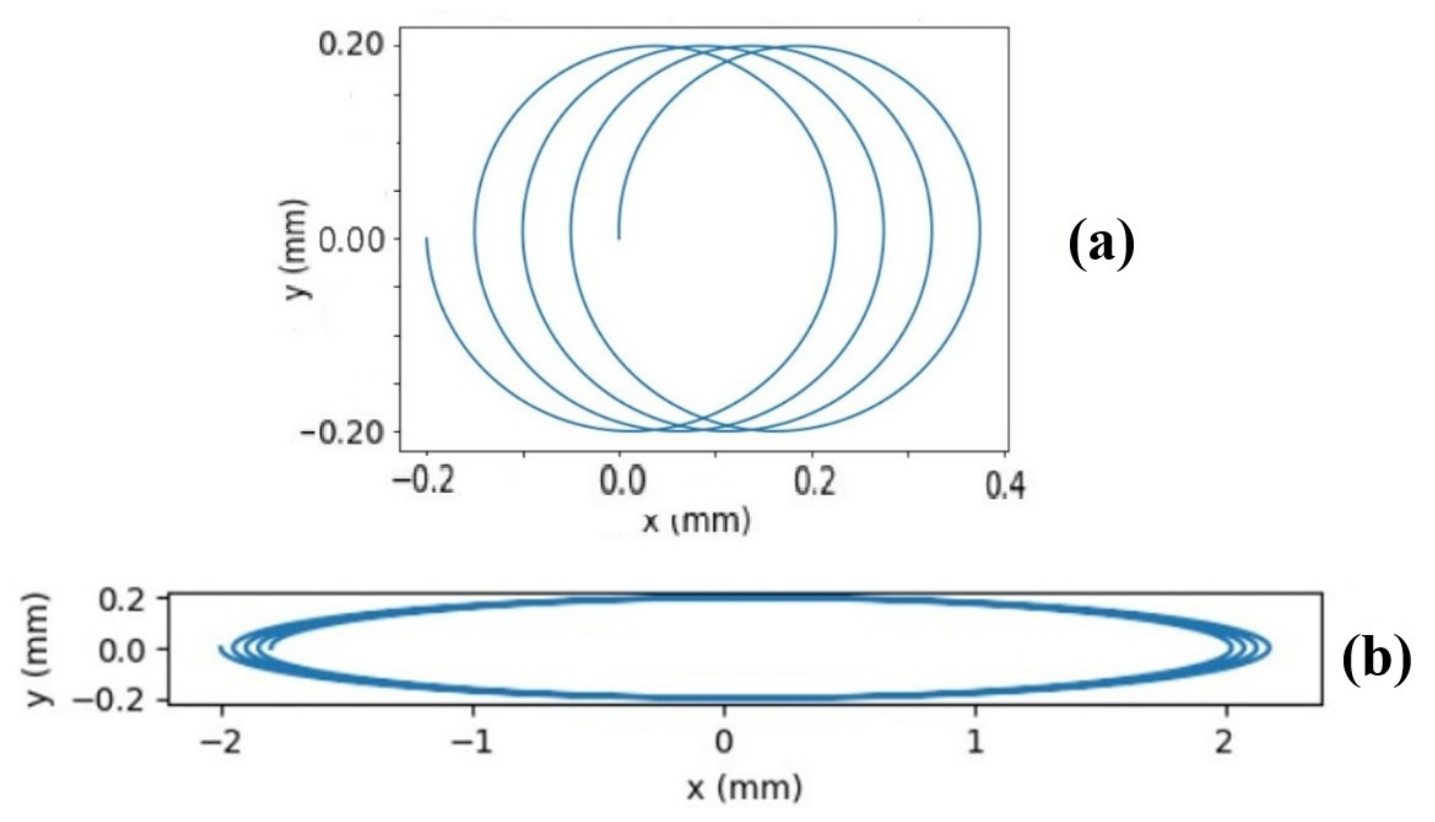
A solution to Equation (2) is found under certain initial and boundary conditions. Since the EBW was performed without preheating, we consider the initial temperature T0 to be equal to room temperature. We consider the two welded plates as a semi-infinite body, limited only by one plane—the upper surface of the plates. The electron beam moves in the direction of the gap between the plates with a speed v, oscillating in a circle or an ellipse (Figure 3a,b) with a certain linear frequency f. We consider the energy source as a combination of two separate sources—surface and volume. We assume that 90% of the energy of the electron beam is concentrated in the volume source (Qv), and the remaining 10% in the surface source (Qs). This ratio was already presented in previous works where its application was validated [26,27,28]. Of course, introducing Nb in the fusion zone may lead to a change in the ratio; however, to keep the results consistent with the verified model, the same ratio was used. Still, it is important to mention that the used ratio is based on a previous work and is not representative of quantitative data, but qualitative assumptions.
The surface source is in the shape of a circle with a radius equal to the radius of the electron beam and a Gaussian intensity distribution. The volume source is in the shape of a cylinder with the same radius and a height equal to the depth of the weld. The energy intensity distribution is also Gaussian for each value of the z coordinate.
Therefore, the temperature of a given point at a given moment in time is determined by the equality:
where TS and TV are the temperatures reached under the action of the surface and volume source, respectively, if all the energy Q of the source is concentrated in each of them.
Figure 3.
Trajectory of the electron beam for four periods during oscillation with frequency f = 200 Hz and movement along the Ox axis with linear velocity v = 10 mm/s along: (a) a circle with radius a = 0.2 mm; (b) a longitudinal ellipse with amplitude a = 2 mm along the Ox axis and amplitude lmax = 0.2 mm along the Oy axis.
As deduced in detail in [26], by using Green’s functions under the above assumptions and boundary and initial conditions, the solution of Equation (2) for an oscillating electron beam is:
where f(x − r cosθ, y – r sinθ, t) is the intensity distribution function of the electron beam and depends on the oscillation trajectory. Here x, y and z are the Cartesian coordinates, and r and θ are the polar coordinates of the integration point.
The temperature distribution in the case of a surface source with an electron beam oscillation along an ellipse is obtained using the following equation:
where the intensity distribution has the form:
The temperature distribution in the case of a volume source with electron beam oscillation along an ellipse is obtained with the following equation:
where
is the source energy distribution, and ζ is the current variable along the height h of the cylinder. Circular oscillation is a special case of elliptical oscillation; therefore, Formulas (7)–(10) are also valid for circular oscillation of the electron beam, with a = lmax.
3. Results
3.1. Experimental Results
3.1.1. X-Ray Diffraction (XRD)
Figure 4 shows the results of the performed analysis in symmetrical Bragg–Brentano mode. Figure 4a shows the diffraction maxima detected for sample EB1, which is the one prepared without a Nb filler. The sample is characterized by a single phase belonging to face-centered cubic (fcc) aluminum. The typical diffraction maxima for this structure were detected, belonging to the (111), (200), (220), and (311) crystallographic planes. Figure 4b depicts the results obtained while studying sample EB2, which was prepared using a Nb filler and a circular electron beam oscillation pattern. Evidently, in this case, a single-phase structure consisting of fcc aluminum was also observed, with the corresponding crystallographic planes. Interestingly, while studying sample EB2, crystallographic peaks corresponding to a pure Nb phase or an intermetallic phase of the type AlyNbx were expected. However, this was not the case. Increasing the life of the melt pool by using elliptical electron beam oscillation was expected to improve the miscibility and dispersion of the Nb phase along the entire volume of the melt pool. Doing this led to a change in the mechanism of structure formation. The Nb particles were successfully integrated into the melt pool, forming a solid solution consisting of αAl and AlyNbx intermetallics. This hypothesis is supported by the detected Al3Nb phase in the case of sample EB3 (Figure 4c). The low concentration of Nb and the high concentration of Al in that compound suggest that the Nb phase was evenly dispersed along the weld seam, forming a homogeneous structure. Along with the Al3Nb intermetallic phase, a pure Al phase was also detected; however, in this case, it is evident that the intensity of the reflections is vastly different. The intensity of the (200) crystallographic plane has decreased significantly. It is important to note that during the XRD experiments, the only intermetallic phase detected was Al3Nb; however, this does not exclude the presence of other intermetallic phases in the volume of the weld seam, but they would have a lower concentration compared to Al3Nb.
Figure 4.
X-ray diffraction patterns of samples (a) EB1, (b) EB2, and (c) EB3.
In order to accurately determine the micro-volume fractions observed parallel to the surface of the samples, the pole density P{hkl} [%] was calculated using Equation (11). In this equation, I{hkl} is the experimentally obtained intensity of a specific family of crystallographic planes with Miller indices h, k, and l. This value is compared to the standard one, I{hkl} standard, given in a crystallographic database—the International Centre for Diffraction Data (ICDD).
The results of the performed calculations are given in Table 3. Based on them, it can be concluded that in the case of samples EB1 and EB2, the preferred crystallographic orientation, characterized by the pole density, is towards the {100} family of crystallographic planes. In the case of successfully integrating the Nb interlayer into the weld seam, the preferred crystallographic orientation changes towards, predominantly, the {111} family of crystal planes. This is possibly attributed to the higher accumulation of heat and longer life of the melt pool. The latter leads to a better distribution of the Nb particles. Interestingly, the {111} family of planes has the lowest free surface energy and thus is the most chemically active orientation of the crystals. However, the {100} family of crystal planes exhibits a much lower density compared to the {111} one. Due to this, it is highly possible that the Nb particles preferentially chemically bonded with the {100} family of planes. This has led to a change in the orientation of the crystals towards the denser crystal planes. Of course, it is possible that this also led to a reduction in lattice imperfections. In order to examine this, the full width at half maximum (FWHM) β [°] was calculated for the {111} family of planes. The results are also presented in Table 3. A noticeable decrease in the peak width is observed in the case of sample EB3 compared to the other ones, indicating, according to the theory of XRD analysis, that a process of annihilation of defects has occurred. This aligns well with the observed change in the crystal orientation. Naturally, in the case of sample EB3, the second most observed crystallographic orientation is towards the {110} family of planes, which are offset from the {111} by 45°. Judging by the observed crystallographic structure, it can be predicted that sample EB3 should have better mechanical properties compared to samples EB1 and EB2 due to the denser stacked lattices and the reduction of lattice imperfections.
Table 3.
Micro-volume shares determined using the pole density P{hkl} and the results of the FWHM (β) for the {111} family of crystal planes.
To further investigate the effect of both adding the Nb filler and varying the technical parameters of electron beam welding on the lattice structure, the lattice constant “a” [Å] was calculated using Equation (12) for fcc structures. It is determined by the corresponding Miller indices for the investigated plane and the interplanar spacing “d” [Å] (distance between the planes).
The results are presented in Table 4. Evidently, there is a very tiny difference in the lattice constant between the different samples. To further evaluate that difference, the volume of the lattice cell V [Å3] was calculated, knowing that in the fcc system V = a3. Based on the performed calculations, it can be said that the volume of the cell decreases in the case of sample EB3 compared to the other ones; however, this decrease is nearly negligible. This indicates that the size, thus volume, of the crystal cells was not affected by either the performed electron beam welding process or the incorporation of the Nb particles.
Table 4.
Lattice constant and lattice cell volume of different crystallographic planes of the aluminum phase found in samples EB1, EB2, and EB3.
3.1.2. Scanning Electron Microscopy (SEM)
Figure 5 shows macroscopic images of all the obtained samples. Figure 5a presents the formed weld seam between the two Al6082-T6 plates without a Nb filler and with circular beam oscillation. A rectangular-shaped weld seam has formed with a length of 5.37 mm and a width of 1.72 mm. In Figure 5b, the formed weld seam using circular beam oscillation and a Nb filler is shown. Its length was 5.32 mm, and its width was 1.65 mm. Lastly, Figure 5c shows the weld seam obtained by using a Nb filler and elliptical beam oscillation. It had a length of 5.49 mm and a variable width due to its keyhole-like shape, which is a commonly observed shape in weld seams obtained using electron beam techniques. At the top, it had a width of 2.44 mm and at the bottom, a width of 1.29 mm. Despite the different technical parameters, nearly the same penetration depth was achieved, with the average being 5.39 ± 0.07 mm.
Figure 5.
Weld seams of samples: (a) EB1; (b) EB2; (c) EB3.
Figure 6a shows a macroscopic image of the obtained weld seam using circular beam oscillation without a Nb filler (EB1). Some larger pores can be seen, which potentially formed due to impurities, or more probably as a result of the dissolution of oxygen. As is known, aluminum has a very high reactivity with oxygen and easily forms the Al2O3 compound. During the welding process, these compounds break down to Al and O atoms. The oxygen atoms agglomerate and, due to the high cooling speed, are trapped in the weld seam in the form of hollow cavities—pores. The observed pores had a mean diameter of 87.8 ± 17.5 µm. An area of the weld seam was also investigated using higher magnification, as shown in Figure 6b. In it, some polishing defects are observed, along with solidification pores. The latter are caused by the rapid expansion and then shrinking of the material. This is why they are also known as “shrinkage pores”. They are commonly observed in an array of welds, but are most commonly seen in aluminum welds due to the high heat input and the high thermal expansion coefficient of aluminum and its alloys.
Figure 6.
Macro-image of the cross-section of the weld seam (a) and microstructure of the bordered area (b) of sample EB1.
Figure 7a shows a macroscopic image of the weld seam obtained using circular beam oscillation and a Nb filler. The weld seam had a rectangular shape, and a certain number of macroscopic pores, with a mean diameter of 125.0 ± 21.3 µm, were seen in the weld seam, particularly close to the bottom of the weld seam. Typically, hollow cavities (pores) form at the root of the weld seam due to either too low welding speeds or insufficient penetration of the electrons and the formation of a partial weld [29]. In these instances, too much material is introduced into the molten pool, and the vapor pressure is not sufficient to stabilize it. As a result of this, the molten material overlaps a certain area within the melt pool, disrupts the flow, and solidifies in an abnormal position, underneath which lies the open cavity. Considering sample EB2, the welding speed is low, but the input power of the electron beam is high. Additionally, the welding is carried out using circular beam oscillation, which increases the heat input. Due to this, not only is full penetration of the material achieved, but some of it has also leaked out of the weld seam through the bottom in both samples EB1 and EB2. In the case of sample EB2, there is a known amount of Nb between the welded surfaces. Since Nb has significantly more dissimilar properties compared to aluminum and its alloys when subjected to the electron beam, it obviously acts differently. Not only does the heating and melting of this material require more time and power (heat input), but also, since aluminum and niobium do not form a solid solution (or form a metastable one), the Nb particles typically spread across the weld seam and form intermetallic compounds with the nearest aluminum particles. This process disrupts the flow of the vapor channel. This is a prerequisite for the formation of cavities and is the most probable mechanism that has led to this result. A higher magnification image is presented in Figure 7b, where large undissolved pieces belonging to a secondary phase are observed. These segments are presumably large agglomerates of undissolved Nb. Studying the macroscopic image again, it can be seen that a large number of such agglomerates can be seen throughout the volume of the weld seam. This also suggests that the heat input was too high, and the cooling was too rapid for Nb to properly melt and be integrated into the weld seam. This is considered a plausible hypothesis, since Nb is known to have a very high melting temperature of 2477 °C, much higher than that of aluminum and its alloys.
Figure 7.
Macro-image of the cross-section of the weld seam (a) and microstructure of the bordered area (b) of sample EB2.
Figure 8a shows a macroscopic image of the weld seam obtained with elliptical beam oscillation. A much more traditional for electron beam welds “keyhole” shape of the weld seam is observed. Additionally, there is minimal difference between the base materials and the weld seam in terms of contrast. No major defects such as cracks and pores were noticed. In Figure 8b, some white precipitates are observed throughout the volume of the weld seam, much like in the case of sample EB2; however, in this case, it is very obvious that their distribution is far more homogeneous, and the size of the obtained agglomerates (presumably Nb or AlxNby) is significantly smaller. This is confirmed by increasing the magnification and studying a selected zone up close. Solidification pores are observed here as well as in the previous cases; however, their concentration is much lower, along with their size. The smaller pores and smaller agglomerates suggest two things. Not only was the Nb filler successfully melted, but it was integrated homogeneously within the weld seam, with most of the agglomerates positioning themselves in the “free” zones between the aluminum crystals. This suggests that an increase in the density of the weld seam was achieved.
Figure 8.
Macro-image of the cross-section of the weld seam (a) and microstructure of the bordered area (b) of sample EB3.
3.1.3. Energy-Dispersive X-Ray Spectroscopy (EDS)
The previous images obtained using the scanning electron microscope necessitated the determination of the spread of chemical elements along the volume of the weld seams. Figure 9 shows the results obtained for sample EB1 prepared with circular beam oscillation and no Nb filler. The detected chemical composition is typical for Al6082-T6 alloys.
Figure 9.
EDX results for sample EB1 prepared without a Nb filler.
Figure 10, Figure 11 and Figure 12 all show images obtained while studying sample EB2 prepared with circular beam oscillation and a Nb filler. In all images, large agglomerates of a secondary phase are observed, much like in the previous images. This supports the theory that Nb was not successfully dissolved and integrated into the weld seam. The agglomerates were investigated, and it was indeed proven that they are Nb particles, which further solidified this hypothesis.
Figure 10.
EDX results for sample EB2 prepared with a Nb filler and circular beam oscillation. Measurement was performed at the marked segment.
Figure 11.
EDX results for sample EB2 prepared with a Nb filler and circular beam oscillation. Measurement was performed at the marked segment.
Figure 12.
EDX results for sample EB2 prepared with a Nb filler and circular beam oscillation. Measurement was performed at the marked segment.
Figure 13 shows an image obtained while investigating sample EB3, which was obtained with elliptical beam oscillation and a Nb filler. It is important to note, as previously done, that in this image, much like in the previous ones, a much lower concentration of solidification pores can be noticed. The agglomerates spread across the weld seam were investigated separately, and the results suggested that these are Al3Nb intermetallic compounds. The latter’s identification was based on the binary phase diagram shown by the authors of the following paper [30]. It is safe to presume that most of the formed intermetallic compounds in the volume of the weld seam were specifically the Al3Nb ones. This presumption is entirely based on the fact that this particular phase has the lowest Gibbs free energy amongst all binary intermetallic compounds between Al and Nb [30]. Not only that, but due to the low quantity of Nb situated between the two aluminum plates, this is the most thermodynamically favorable, stable, and easiest-to-form intermetallic compound. The Al3Nb compound is characterized by high hardness [31] and brittleness [32], and is typically undesired when welding dissimilar metals and alloys. However, in the present case, as mentioned above, it is hypothesized that the presence of such intermetallics reduces the concentration of defects in the weld seam, thus increasing the density and increasing its strength.
Figure 13.
EDX results for sample EB3 prepared with a Nb filler and elliptical beam oscillation. Measurement was performed at the marked segment.
Further examination of the weld seam of sample EB3 was conducted and shown in Figure 14. Although pure Nb was not detected as a separate phase using the X-ray diffraction experiments, it is evident that some undissolved Nb agglomerates exist within the volume of this weld seam as well. Their size and concentration, compared to those observed in the case of sample EB2, are significantly smaller.
Figure 14.
EDX results for sample EB3 prepared with a Nb filler and elliptical beam oscillation. Measurement was performed at the marked segment.
3.1.4. Nb and AlyNbx Phases Particle Size
Table 5 presents the particle size of the niobium grains in the case of sample EB2 and the size of the particles in sample EB3, which are presumed to be constituted predominantly of the Al3Nb phase. The results indicated that in the case of using circular beam oscillation, the size of the Nb particles was in the range of 33.11–61.41 μm. This indicates that they were not efficiently melted, integrated, and spread across the primary aluminum matrix. This also indicates poor mixing of the materials during the liquidus stage of the melt pool. With the increase in the size of the melt pool and by modulating the heat input by using elliptical-shaped beam oscillation, the mixing of the materials was improved significantly. The decrease in the size of the particles of the secondary and third phases, namely Al3Nb and Nb, to values in the range of 3.63–7.75 μm signifies this process. This not only suggests that the mechanical properties of the fusion zone of sample EB3 should be improved, but also that a homogeneous distribution of the Al3Nb and Nb particles along the volume of the fusion zone is observed.
Table 5.
Size of the Nb and Al3Nb (in the case of EB3) particles.
3.1.5. Solidification Pores
Aluminum is widely known for the formation of the so-called solidification pores. This is a result of the extremely high thermal expansion, thus shrinkage of the material, particularly when subjected to high-temperature treatment with high thermal gradients. This is especially true when welding processes are considered. In the present case, solidification pores were also detected while studying the microstructure of the samples. In the fusion zone of sample EB1, the size of the solidification pores was in the range of 3.75–8.55 μm; in the case of sample EB2, it was 1.31–3.67 μm; and regarding sample EB3, it was 1.08–4.31 μm. Evidently, in both cases, the application of an intermediate layer of Nb between the aluminum alloy plates contributed to the reduction of the size of the solidification pores. This is attributed to the high solidification speed of the aluminum matrix. During this process, it is most energetically efficient for the Nb particles to accommodate the empty areas (cavities) in the solid solution and form chemical bonds with adjacent crystals. The results of the performed measurements suggest that an increase in the density of the fusion zone is to be expected, which may affect the mechanical properties as well.
3.1.6. Hardness
The results of the Vickers hardness experiments are summarized in Table 6. The microhardness of five different zones of the samples was determined—the left Al6082-T6 plate (LP); the heat-affected zone between the left plate and the fusion zone (HAZL); the fusion zone (FZ); the heat-affected zone between the FZ and the right plate (HAZR); and the right Al6082-T6 plate (RP). Based on the results, it can be seen that the hardness of the left and right Al6082-T6 plates is approximately the same, with an average between all samples of: LP—93.3 HV0.05; RP—93.5 HV0.05. Previous research indicates that the microhardness of Al6082-T6 is about 95 HV [33], which is in agreement with the current results and shows the low thermal effect the EBW process had on the Al6082-T6 plates beyond the welding area. The hardness in the heat-affected zones is in all cases lower than that of the unaffected aluminum alloy plates, but higher than that of the fusion zone. The fusion zone of sample EB1, welded without a filler, had an average hardness of 72.6 ± 3.3 HV0.05. Adding the Nb filler between the aluminum alloy plates and subsequently welding them increased the hardness of both the heat-affected zones and the fusion zone. This effect was hypothesized previously in this work since theoretically the addition of Nb reduced the expansion and shrinkage of the base aluminum matrix, resulting in the formation of fewer defects. The Nb particles also increased the density of the fusion zone, which in turn is responsible for the increase in hardness. The highest values of hardness were obtained while studying sample EB3. This is completely in agreement with the previous analysis, where a major decrease in the concentration of defects was detected. Intermetallic structures with high hardness formed within the volume of the weld seam of that sample. Additionally, they were homogeneously spread across the weld seam. This is also a major prerequisite for the increase in hardness values. It is important to note that in the case of sample EB3, the microhardness is much more uniform across the sample, which theoretically should result in better uniformity, higher strength, and more predictable mechanical behavior of the joint. In the case of sample EB1, the microhardness discrepancy between the highest and lowest values was as much as 21 HV, whereas for sample EB3, it was only 11.8 HV.
Table 6.
Vickers hardness of samples EB1, EB2, and EB3 in the left plate, HAZ of the left plate, fusion zone, HAZ in the right plate, and the right plate.
3.1.7. Tensile Strength
The tensile test results of samples EB1–EB3 and of untreated Al6082-T6 are shown in Table 7. Sample EB1 had a yield strength of 134 ± 4 MPa and an ultimate tensile strength of 225 ± 8 MPa. This means that the UTS/YS ratio of this sample is 1.68. In the case of sample EB2, the yield strength was 164 ± 4 MPa, the UTS was 203 ± 7 MPa, and the ratio was 1.24. Applying a Nb layer with an elliptical-shaped oscillation of the electron beam resulted in an increase in the ultimate tensile strength to 275 ± 8 MPa at about the same YS of 165 ± 9 MPa. The UTS/YS ratio in this case is 1.67. This means that due to the poor miscibility of the Nb particles in the case of sample EB2 and the presence of defects, the strength of the weld seam did not exceed, and was even slightly lower than, that of the sample prepared without a Nb layer. Using an elliptical-shaped electron beam oscillation resulted, as proven by other analyses, in better miscibility of the Nb particles with the Al matrix, the formation of intermetallic compounds, their better scattering along the volume of the weld seam, the formation of smaller particles, annihilation of defects, and more. All of this naturally resulted in improved mechanical properties of the samples, particularly the hardness and tensile properties. The UTS/YS ratio of sample EB3 is comparable to that of the sample prepared without a Nb layer. The standardized value of this ratio typical for steel-framed structures is 1.25 [34]. Although this ratio cannot be directly used as a reference value for the obtained samples in the current work, it signifies that the higher it is, the higher the amount of deformation capacity the material has before fully fracturing (complete failure of the construction). This is exceptionally important in applications where a preemptive warning of the failure of the construction is necessary for safety purposes (for example, when people are inside the construction and need time to escape). Lower ratio joints fail suddenly without a warning, which is highly desirable in other particular cases (for example, when a specific point in the construction is designed to fail to protect the rest of it or other constructions adjacent to it). All obtained values were compared to the tensile strength of the raw as-delivered material. It had a yield strength of 217 ± 7 MPa, and a tensile strength of 353 ± 11 MPa. This means it originally, in its pure form, has a UTS/YS ratio of 1.62. The closest sample in terms of tensile strength to the as-delivered material was sample EB3, which had a UTS 22% lower than the raw Al6082-T6 plates. Evidently, the UTS/YS ratio of sample EB3 relative to the raw material was comparable, indicating that performing electron beam welding on Al6082-T6 plates with a Nb layer using an elliptical-shaped beam oscillation had a positive effect in improving the joint structure, which resulted in improved mechanical properties compared to those of the raw material. Furthermore, the safety standards for the deformation of the material after the elastic stage were also preserved. Table 7 also contains data taken from previous research regarding welding of aluminum alloy components. In the case of [35], Al6082-T6 samples were prepared using electron beam welding without a filler. The obtained samples had a maximum average tensile strength of 250 MPa, which is within the range of data obtained during this research. For comparison, data regarding the UTS value of the much more conventional metal inert gas (MIG) welded Al6082-T6 plates are also given in Table 7, where the average value reached 222.09 MPa [36].
Table 7.
Tensile test results for samples EB1, EB2, EB3, and as-delivered Al6082-T6 plates.
3.2. Analytical Model Results
In the present work, seemingly only two results are presented, although there were three investigated samples. This is true because it is presumed that the results for samples EB1 and EB2 are the same since in both cases the same technical parameters were used. Indeed, the Nb interlayer must have changed the temperature in the fusion zone during the welding process, but this change was calculated to be negligible.
The thermophysical parameters of the studied Al6082-T6 alloy used in the mathematical modeling are presented in Table 8. They were selected based on the data presented by Samad et al. [37]. According to the authors of [38], the change in the thermophysical parameters of aluminum alloys with temperature changes does not have a major impact on the results of the computer modeling, and the use of values at room temperature is satisfactory.
Table 8.
The thermophysical parameters of Al6082-T6 in a solid state at room temperature.
The numerical integration to obtain the temperature distribution during the process of electron beam welding of samples EB1(EB2) and EB3 was performed by utilizing the technical parameters presented in Section 2.1 of this paper. The source power Q is calculated by the formula:
where ηeff is the efficiency coefficient and Q1 = Ua*Ib is the source power (Ua and Ib are the accelerating voltage and beam current, respectively).
The efficiency coefficient ηeff is assumed to have a value of 0.95. This coefficient shows how much of the energy from the source is actually transferred to the body. According to the literature data, it has a value of 0.95–0.97 [29].
In Figure 15a, the distribution of the temperature fields in a semi-cross-sectional plane of samples EB1 and EB2 is shown. Evidently, the temperature is the highest at the center of the weld seam. With the increase in distance along the side of the joint, the temperature decreased rapidly. This is typical for welding processes involving highly concentrated energy sources, particularly an electron beam source. This highly localized thermal effect is caused by the limited interaction between the electrons and the target (in this particular case, the Al6082-T6 plates). This is one of the advantages of the electron beam welding process. Figure 15b shows a 3D representation of the weld seam for samples EB1 and EB2 formed using circular beam oscillation. The temperature of the molten pool is the highest at the top, where the vapor channel is the largest, and the interaction of the material with the bombarding electrons is the highest. In Figure 15a,b, a non-linearity of the temperature distribution along the “z” axis is visible up until about 3 mm in depth. This non-linearity is much more pronounced in Figure 15b. At this moment, it is important to note that the temperature model is a purely mathematical model (as mentioned above), which means the temperature fields were generated based on calculations of the entire volume of the weld seam. This means that the “z” parameter was assumed to be equal to the entire thickness of the Al6082-T6 plates. In the case of samples EB1 and EB2, though, looking at the SEM images revealed that the input heat of the electron beam was too high and some of the material leaked out. The formed cavity at the top of the weld seam has a depth of about 3 mm and is equivalent to the depth of the observed non-linearity in the model. This means that, although the model was not capable of fully representing the “leak” of the molten pool, it was adequate to predict it.
Figure 15.
Simulation of the distribution of temperature fields for samples EB1 and EB2: (a) in a semi-cross-sectional plane and (b) a 3D representation of the weld seam.
Of course, the case where elliptical oscillation of the electron beam was applied was investigated as well using the mathematical model. The results of the calculations are presented in Figure 16. At first, the semi-cross-section of the molten pool was investigated, as shown in Figure 16a. A lower dispersion of temperature along the “y” coordinate is observed as compared to samples EB1 and EB2. The shape and size of the molten pool are also highly accurate to the real one. Figure 16b shows a 3D representation of the distribution of the temperature fields during the electron beam welding process of sample EB3 with elliptical beam oscillation. Obviously, the temperature spot at the surface is much larger due to the much larger focal spot of the electron beam. During the welding process, only a partial penetration was achieved up to about 5.5 mm from the surface of the Al6082-T6 plates. Although the mechanism of temperature distribution is quite clear, the presented mathematical model visually aids the comprehension of the processes that have occurred and the reason why. The much larger focal point of the electron beam distributed the temperature across a much larger volume of the plates. This reduced the efficiency of the electron beam, thus reducing its penetration. There is a much larger and more important merit to using elliptical beam oscillation, as evident in Figure 16b. This is the initial preheating of the weld seam. This not only reduces the internal stress of the joint, but also increases the duration of the heating (the life of the melt pool). This helped tremendously with the melting, spreading, and chemical bonding of the Nb particles and the aluminum matrix in order to form a homogeneous joint comprised of an aluminum matrix with predominantly Al3Nb intermetallics, with a high density and a low concentration of defects.
Figure 16.
Simulation of the distribution of temperature fields for samples EB3: (a) in a semi-cross-sectional plane and (b) a 3D representation of the weld seam.
4. Discussion
This work utilizes an electron beam as a means for electron beam welding of similar materials, in particular Al6082-T6. The electron beam process is widely known for the high thermal gradients that form during the process due to the very localized heat input. This is highly favorable for welding precise pieces with low tolerances, welding close to materials that can easily be damaged by the heat, or, most importantly, when welding hard-to-melt materials such as refractory metals—Nb, W, Mo, Ta, and more. However, in the present case, the electron beam source was used to weld an aluminum alloy (Al6082-T6), which has a significantly lower melting point of about 650 °C. This necessitates a much more delicate approach concerning the selection of the technical parameters. The method by which the Al6082-T6 samples are subjected to the heat input needs to be carefully modulated. Naturally, using a highly focused electron beam would easily be able to melt the aluminum alloy; however, due to the highly localized thermal input and the rapid solidification in a very limited volume of material, tremendous thermal stresses are generated that often result in the formation of defects such as cracks either in the weld seam itself or in the heat-affected zone. Due to this, a very common practice is the application of beam oscillation. The electron beam can be controlled precisely in order to form a specific oscillating pattern of welding, which can be sinusoidal, circular, or elliptical, among many other geometries [39]. This leads to a change in the distribution of heat and the mechanism of melting, mixing of the materials, and solidification. In the case of circular beam oscillation, it was proven by Hagenlocher et al. [40] that when using circular beam oscillation of a laser beam heat source, the solidification speed decreases. In a previous work, Kaisheva et al. [41] proved that increasing the oscillation radius increases the localized heat input and also decreases the solidification speed. The reduction of the solidification speed drastically changes the mechanism of formation of the weld seam. The more spread out the thermal gradients are, the weaker the Gibbs–Marangoni effect becomes, which is accompanied by a much more controlled and less turbulent flow of the melt pool [42]. Comparing the results of the theoretical mathematical model of samples EB1, EB2, and EB3, it is obvious that in the case of using elliptical beam oscillation, the thermal gradients are much weaker, as the temperature is much more evenly distributed along the volume of the weld seam and the plates. Theoretically, this should decrease the influence of the Gibbs–Marangoni effect in that sample.
The X-ray diffraction results show a change in the texturing of the weld seam of sample EB3 towards the {111} family of crystallographic planes as compared to the other samples, where the texturing was towards the {100} family of planes. In order for the {111} texturing to form, a much slower and less turbulent process of solidification is required, with lower thermal stresses. The (111) crystal-plane-oriented structures are characterized by the highest symmetry and density in the fcc system [43]. They are also the most chemically stable [43], which improves the stability of the formed joint. Additionally, the formation of a texture towards the {111} family of planes also suggests that a process of annihilation of defects has occurred. This all suggests that an increase in the mechanical properties is to be expected. Another proof for the reduction in the Gibbs–Marangoni effect is not only the better bonding between the Nb particles and the aluminum ones and the formation of the Al3Nb intermetallic phase, but also the even distribution of this phase along the entire volume of the joints. Homogeneity is one of the most important factors when attempting to form weld seams with intermetallic compounds since poor mixing could cause the formation of brittle agglomerates (as in the case of sample EB2) or uneven solidification and the formation of major defects [44].
Obviously, there is a vast number of factors that influence the Gibbs–Marangoni effect, and during this work its exact qualitative effect was not observed. In terms of thermal effects, as mentioned above, Nb is a refractory metal with a melting temperature of 2477 °C. Considering this, at first glance it seems impossible to successfully form intermetallic compounds of the two primary materials used in this work—Al and Nb. However, previous studies indicate that binary IMCs of these materials form at temperatures between 1000 °C and 1400 °C [45]. Since most commercially used aluminum alloys melt at temperatures within the range of 600–700 °C, the task of integrating Nb in the melt pool while attempting to weld aluminum alloy components is still a significant challenge. A strong hypothesis indicating that this may be possible is the high thermal conductivity of aluminum, which is greatly reduced when it transitions from a solidus to a liquidus stage. During this process, most of the heat is transferred to the Nb layer between the plates, which is later reduced to Nb particles. Clearly, the obtained results indicated that the size of the Nb particles was significantly reduced (about 10 times) when switching from circular beam oscillation to elliptical. Studying images 15 and 16 that correspond to the results of the mathematical model, the reason why is obvious. The larger area the electron beam covers results in a much shallower thermal footprint; however, it is much wider. In the case of electron beam welding of Al6082-T6 plates with a Nb filler, this was beneficial since more of the thermal energy, after the aluminum alloy melted, was distributed to the Nb filler, and additionally, it was exposed to the formed thermal gradients for a significantly longer amount of time. The larger “keyhole” is also much more beneficial thermodynamically for the formation of intermetallic compounds. Evidently, the Al3Nb intermetallic compound has the lowest free energy of formation among all possible compounds of the NbxAly binary system [46]. Although the chemical composition of the entire volume of the weld seam of sample EB3 was not determined, it is safe to assume it is predominantly composed of the primary aluminum matrix with the homogeneous spread of the Al3Nb phase. Having that in mind, it is important to note that the formation of other intermetallic phases from the binary NbxAly system is highly possible; in fact, it is probable. In the present work, undissolved Nb particles in the volume of sample EB3 were also still noticed. This is highly undesirable and is probably a result of a slightly too short heating/mixing time during the liquidus stage.
Despite the presence of pure Nb in the volume of sample EB3, a consistent increase in the hardness of the fusion zone was noticed across all samples, starting from the one formed without a filler. An increase in the hardness of the samples was observed from the raw plates towards the weld seam as well. The latter had the highest detected values. In the literature, there is mixed information concerning hardness distribution trends. In one instance, the heat-affected zone has superior mechanical properties compared to the fusion zone, as proven by Lu et al. [47], who investigated tungsten inert gas (TIG) welding of Al7055, and in other instances, such as electron beam welding of Al7075 [48], the trend is reversed, and the lowest hardness was obtained in the heat-affected zone. In the present article, as described, the microhardness follows an increasing trend from the weld seam towards the raw plates. This is attributed to a number of reasons. One of those reasons is the application of beam oscillation, which was not used in either example. This led to the formation of “aggressive” high thermal gradients. Additionally, the incorporation of the Nb particles and the formation of IMCs (in the case of sample EB3) substantially increased the hardness.
Despite the linear increase in hardness of the samples, the ultimate tensile strength of sample EB2 was lower compared to sample EB1. Those samples were prepared using identical technical parameters, with the only difference being the application of the filler. To a great extent, applying fillers during the welding of identical materials is like forming a dissimilar joint. All materials have to be properly melted, diluted, chemically reacted with one another, etc. When the process is uncontrolled, an opportunity to form a chaotic melt pool is created. During this, a number of different zones, as shown previously by the authors of [41], form, which may consist of either only a single-phase structure or a double- or multi-phase one. Additionally, IMCs may form, but they are predominantly situated in specific areas in the form of large agglomerates. This causes major instability of the melt pool, especially during the solidification stage. Not only may separate zones not form strong chemical compounds with one another, but the formation of separate zones also results in uneven thermal stresses. Considering that the primary material of choice in this case is an aluminum alloy, most of the thermal stresses in the weld seam are probably solidification/shrinkage stresses, which form during the transition from liquidus to solidus state, and are exceptionally great when it comes to aluminum and its alloys. In fact, aluminum is widely known to have one of the highest thermal expansion/shrinkage coefficients of all known metals and alloys. Although these stresses were not determined in the present work, it is possible to generate the following hypothesis—in the case of sample EB2, the solidification/shrinkage stresses formed during the solidification stage were high enough to separate the weak bonds between the unreacted Nb particles and the aluminum matrix. It is important to mention that a reduction of the solidification pores was observed in the case of sample EB2 compared to EB1, which can probably explain the increase in hardness; however, chemical bonding and homogeneity, as opposed to density, are much more important when it comes to static axial stresses such as the ones applied during the tensile testing. This is also most probably the reason sample EB3 exhibited the highest tensile strength.
Resistance to static stresses is highly important for any weld between metals and alloys; however, another factor that is very important is the ductility of the joints. Higher ductility joints typically experience more plastic deformation prior to fracture. This is important for applications where catastrophic sudden failure of the stressed components is highly unwanted. It is commonly known that intermetallics, and particularly binary intermetallics of the system NbxAly, are highly brittle with low ductility. The application of an electron beam weld in reduced the elongation of the material in all cases. When comparing the different samples, the highest deformation was observed in the case of sample EB1, which was prepared without a filler. Then, in the case of samples EB2 and EB3, the elongation is lower, and the lowest values are for sample EB2. These results support the hypothesis that large thermal internal stresses have formed in the case of sample EB2, which resulted in lower chemical bonding. Observing the results of sample EB3, the elongation is higher, which also supports the hypothesis that the thermal internal stresses are lower; however, due to the high concentration of IMCs, the elongation of the joint was still lower compared to the sample without a filler.
In summary, the application of elliptical beam oscillation with a length of 2 mm and a width of 0.2 mm was sufficient to successfully incorporate a Nb filler into an electron beam weld formed between two Al6082-T6 plates. Niobium reacted to a great extent with the primary aluminum matrix, resulting in the preferred formation of the Al3Nb intermetallic phase, along with a small concentration of other IMCs. This resulted in improved density of the weld seam, higher hardness and static strength. However, some noticeable problems exist that need to be resolved in order to optimize the joint formation. Firstly, and most noticeably, using elliptical beam oscillation with this size did not achieve full penetration of the electron beam; thus, a weld with a depth of only about 5.5 mm was achieved when the samples used have a thickness of 8 mm. Further optimization of the technical parameters needs to be performed in order to achieve similar structural and mechanical results at higher depths of welding. Another issue in the current work is that some undissolved Nb is still present in the structure of sample EB3, which needs to be fully incorporated into the weld seam. As mentioned above, this can probably be achieved by increasing the “exposure” time, or in other words, increasing the duration of the liquidus stage, and by extension, increasing the heating time. This should theoretically benefit the formation of chemical bonds between the Al matrix and the Nb filler. Potentially, the increased liquidus time may result in an increased depth of the melt pool. Lastly, an issue that was noticed during this work was the accuracy of the model. Although the accuracy is relatively high, more is to be desired, particularly regarding the modeling of multicomponent systems that incorporate two or more different materials with different thermophysical properties.
Additionally, it would be interesting to investigate how the length of the elliptical oscillation would affect the structural and mechanical properties. Also, it may be interesting to examine how the Nb concentration would affect the technological conditions, and whether applying a lower concentration of Nb between the plates would ease its incorporation and the formation of intermetallics or not, and whether that would preserve the currently obtained benefits from the incorporation of a Nb filler.
5. Conclusions
In the present work, the possibility of electron beam welding of Al6082-T6 plates with a Nb filler at different technical parameters was investigated. A numerical model was generated, and the theoretically calculated data were compared to real experimental results. The following list of conclusions was generated based on the results:
- -
- Electron beam welding with circular beam oscillation with a radius of rosc = 0.2 mm at a power of 2700 W led to excessive melting of the materials, which were partially ejected from the bottom of the weld seam;
- -
- A too-short life of the melt pool was achieved by welding the Al6082-T6 plates with circular beam oscillation with a radius of rosc = 0.2 mm, which resulted in poor miscibility, only partial melting of the Nb filler, and poor formation of intermetallic compounds;
- -
- Applying elliptical beam oscillation with a length l = 2 mm and a width d = 0.2 mm led to preheating of the weld seam and a much longer life of the melt pool, which in turn resulted in excellent miscibility between Nb and Al and the formation of a homogeneous distribution of Al3Nb intermetallic particles;
- -
- The homogeneous distribution of Al3Nb particles in the case of using elliptical beam oscillation increased the density of the weld seam, which improved both the hardness and the tensile strength, which had values of 83.4 ± 3.5 HV and 275 ± 8 MPa, respectively;
- -
- The formed mathematical thermal model had good accuracy compared to the experimentally obtained samples and was able to provide invaluable insight into the thermal processes that occur during the electron beam welding process, and even predict the partial “over-melting” of samples EB1 and EB2 and the formation of a cavity at the surface of the weld seams.
During this work, successful incorporation of Nb into the weld seam in the form of Al3Nb intermetallic particles was achieved by varying the technical parameters of electron beam welding of Al6082-T6 plates. Excellent mechanical properties were achieved; however, many more investigations are needed in order to optimize the process in relation to achieving even higher-strength joints that are either equal in strength to, or even surpass, the as-delivered material. It is also important to find the optimal technical parameters for electron beam welding of Al6082-T6 plates, where full penetration would be achieved. In the present work, it is hypothesized that this could be achieved by slightly increasing the power of the electron beam.
Author Contributions
Conceptualization, D.K., M.O., S.V. and A.A.; methodology, D.K., A.A., S.V., I.I., F.P., N.I., E.L., D.D., V.D., G.K., L.V., B.S. and M.O.; formal analysis, D.K., I.I., F.P., N.I., D.D., E.L., A.A., S.V., V.D., G.K., L.V., B.S. and M.O.; investigation, D.K., A.A., S.V., V.D., G.K., B.S. and M.O.; writing—original draft preparation, D.K. and G.K.; writing—review and editing, D.K., G.K. and S.V.; visualization, D.K. and M.O.; project administration, M.O. and S.V. All authors have read and agreed to the published version of the manuscript.
Funding
This research was funded by the European Regional Development Fund under the Operational Program “Scientific Research, Innovation and Digitization for Smart Transformation 2021–2027”, Project CoC “Smart Mechatronics, Eco- and Energy Saving Systems and Technologies”, BG16RFPR002-1.014-0005.
Data Availability Statement
The data presented in this study are available on request from the corresponding author due to legal and ethical reasons.
Acknowledgments
The author team would also like to express their deepest gratitude to Antonia Zoto and Vladimir Angelov for the tremendous help and inspiration during the preparation of this work!
Conflicts of Interest
The authors declare no conflicts of interest.
Abbreviations/Nomenclature
The following abbreviations/nomenclature are used in this manuscript:
| DC | Direct current |
| IMC | Intermetallic compound |
| EBW | Electron beam welding |
| SMAW | Shielded metal arc welding |
| GMAW | Gas metal arc welding |
| GTAW | Gas tungsten arc welding |
| LBW | Laser beam welding |
| FSW | Friction stir welding |
| XRD | X-ray diffraction |
| SEM | Scanning electron microscopy |
| EDX | Energy-dispersive X-ray spectroscopy |
| FWHM | Full width at half maximum |
| fcc | Face centered cubic |
| LP | Left plate |
| HAZL | Heat affected zone left |
| FZ | Fusion zone |
| HAZR | Heat affected zone right |
| RP | Right plate |
| YS | Yield strength |
| UTS | Ultimate tensile strength |
| MIG | Metal inert gas |
| TIG | Tungsten inert gas |
| ρ [kg/m3] | Density |
| Cp [J/(kg.K)] | Specific heat capacity |
| λ [W/(m.K)] | Thermal conductivity |
| α [mm2/s] | Thermal diffusivity |
| Ua [kV] | Accelerating voltage |
| Ib [mA] | Beam current |
| Q1 [W] | Power of the electron beam |
| ηeff | Power efficiency coefficient |
| Q [W] | Power introduced into of the body |
| QS [W] | Power of the surface source (10% of Q) |
| QV [W] | Power of the volume source (90% of Q) |
| T0 [°C] | Initial temperature |
| h [mm] | Depth of penetration of the electron beam |
| T(x,y,z) [°C] | Temperature of the point with coordinates (x,y,z) |
| x,y,z [mm,mm,mm] | Cartesian coordinates |
| r,θ,ζ [mm,rad,mm] | Cylindrical (ζ) and polar (r,θ) coordinates |
| P{hkl} [%] | Pole density |
| a [Å] | Lattice constant |
| d [Å] | Interplanar spacing |
| V [Å3] | Volume of the unit cell |
References
- Gong, H.; Liu, J.; Feng, H. Review on anti-loosening methods for threaded fasteners. Chin. J. Aeronaut. 2022, 35, 47–61. [Google Scholar] [CrossRef] [Scilit]
- Sharvan, C.; Radhika, N.; Kumar, N.; Sivasailam, B. A review on welding techniques: Properties, characterizations and engineering applications. Adv. Mater. Process. Technol. 2023, 10, 1126–1181. [Google Scholar] [CrossRef] [Scilit]
- Xu, Y.; Liu, Q.; Xu, J.; Xiao, R.; Chen, S. Review on multi-information acquisition, defect prediction and quality control of aluminum alloy GTAW process. J. Manuf. Process. 2023, 108, 624–638. [Google Scholar] [CrossRef] [Scilit]
- Weglowski, M.; Blacha, S.; Phillips, A. Electron beam welding—Techniques and trends—Review. Vacuum 2016, 130, 72–92. [Google Scholar]
- Luo, Y.; Liu, J.; Ye, H. Bubble flow and the formation of cavity defect in weld pool of vacuum electron beam welding. Vacuum 2011, 86, 11–17. [Google Scholar] [CrossRef] [Scilit]
- Huang, C.; Wang, T.; Lee, C.; Han, W. A study of the heat-affected zone (HAZ) of an Inconel 718 sheet welded with electron-beam welding (EBW). Mater. Sci. Eng. A 2005, 398, 275–281. [Google Scholar] [CrossRef] [Scilit]
- Das, D.; Pratihar, D.; Roy, G. Cooling rate predictions and its correlation with grain characteristics during electron beam welding of stainless steel. Int. J. Adv. Manuf. Technol. 2018, 97, 2241–2254. [Google Scholar] [CrossRef] [Scilit]
- Li, L.; Fu, P.; Lin, B.; Wang, X. Effect of Preheating and Post-Heating on the Microstructures and Mechanical Properties of TC17-Ti2AlNb Joint with Electron Beam Welding. Materials 2024, 17, 1654. [Google Scholar] [CrossRef] [Scilit] [PubMed]
- Yamamoto, N.; Liao, J.; Watanabe, S.; Nakata, K. Effect of Intermetallic Compound Layer on Tensile Strength of Dissimilar Friction-Stir Weld of a High Strength Mg Alloy and Al Alloy. Mater. Trans. 2009, 50, 2833–2838. [Google Scholar] [CrossRef] [Scilit]
- Li, S.; Yue, X.; Li, Q.; Peng, H.; Dong, B.; Liu, T.; Yang, H.; Fam, J.; Shu, S.; Qiu, F.; et al. Developments and applications of aluminum alloy for aerospace industry. J. Mater. Res. Technol. 2023, 27, 944–983. [Google Scholar] [CrossRef] [Scilit]
- Mahfoud, M.; Emadi, D. Aluminum Recycling—Challenges and Opportunities. Adv. Mater. Res. 2009, 83–86, 571–578. [Google Scholar]
- Samuel, A.; Samuel, E.; Songmene, V.; Samuel, F. A Review on Porosity Formation in Aluminum-Based Alloys. Materials 2023, 16, 2047. [Google Scholar] [CrossRef] [Scilit] [PubMed]
- Hidnert, P.; Krider, H. Thermal Expansion of Aluminum and Some Aluminum Alloys. J. Res. Natl. Bur. Stand. 1952, 48, 209–220. [Google Scholar] [CrossRef] [Scilit]
- Gatzen, M.; Tang, Z.; Vollertsen, F. Effect of electromagnetic Stirring on the Element Distribution in Laser Beam Welding of Aluminum with Filler Wire. Phys. Procedia 2011, 12, 56–65. [Google Scholar] [CrossRef] [Scilit]
- Wang, T.; Zhang, Y.; Li, X.; Zhang, B.; Feng, J. Influence of beam current on microstructures and mechanical properties of electron beam welding-brazed aluminum-steel joints with an Al5Si filler wire. Vacuum 2017, 141, 281–287. [Google Scholar] [CrossRef] [Scilit]
- Oladimeji, O.; Taban, E. Trend and innovations in laser beam welding of wrought aluminum alloys. Weld. World 2016, 60, 415–457. [Google Scholar] [CrossRef] [Scilit]
- Chen, G.; Yin, Q.; Zhang, G.; Zhang, B. Fusion-diffusion electron beam welding of aluminum-lithium alloy with Cu nano-coating. Mater. Des. 2020, 188, 108439. [Google Scholar] [CrossRef] [Scilit]
- Bowden, D. Properties and processing of niobium aluminides. Mater. Manuf. Process. 1989, 4, 85–101. [Google Scholar] [CrossRef] [Scilit]
- Chen, R.; Dong, S.; Guo, J.; Ding, H.; Su, Y.; Fu, H. Microstructure evolution and mechanical properties of directionally-solidified TiAlNb alloy in different temperature gradients. J. Alloys Compd. 2015, 648, 667–675. [Google Scholar] [CrossRef] [Scilit]
- Almeida, A.; Petrov, P.; Nogueira, I.; Vilar, R. Structure and properties of Al-Nb alloys produced by laser surface alloying. Mater. Sci. Eng. A 2001, 303, 273–280. [Google Scholar] [CrossRef] [Scilit]
- Ting, W.; Binggang, Z.; Jicai, F.; Qi, T. Effect of a copper filler on the microstructure and mechanical properties of electron beam welded titanium-stainless steel joint. Mater. Charact. 2012, 73, 104–113. [Google Scholar] [CrossRef] [Scilit]
- Gan, Z.; Chen, G.; Teng, X.; Zhang, L.; Zhu, L.; Leng, X. Microstructure and mechanical properties of electron beam welded joint of Nb refractory metal to 304 austenitic steel. Int. J. Refract. Met. Hard Mater. 2025, 130, 107177. [Google Scholar] [CrossRef] [Scilit]
- Beygi, R.; Galvao, I.; Akhavan-Safar, A.; Pouraliakbar, H.; Fallah, V.; Silva, L. Effect of Alloying Elements on Intermetallic Formation during Friction Stir Welding of Dissimilar Metals: A Critical Review on Aluminum/Steel. Metals 2023, 13, 768. [Google Scholar] [CrossRef] [Scilit]
- ISO 6507-1:2018; Metallic Materials—Vickers Hardness Test—Part 1: Test Method. ISO: Geneva, Switzerland, 2018.
- ISO 6892-1:2009; Metallic Materials—Tensile Testing—Part 1: Method of Test at Room Temperature. ISO: Geneva, Switzerland, 2009.
- Kaisheva, D.; Angelov, V.; Petrov, P. Simulation of heat transfer at welding with oscillating electron beam. Can. J. Phys. 2019, 97, 1140–1146. [Google Scholar] [CrossRef] [Scilit]
- Kaisheva, D.; Petrov, P.; Bokuchava, P.; Papushkin, I. Study of residual stresses in electron beam welded constructive steel via neutron diffraction method. Bulg. Chem. Commun. 2020, 52, 129–133. [Google Scholar]
- Petrov, P.; Kaisheva, D.; Bokuchava, G.; Papushkin, I. Study of residual stresses during electron beam welding of alloyed steels using neutron diffraction. Bulg. Chem. Commun. 2018, 50, 85–90. [Google Scholar]
- Shiller, S.; Heisig, U.; Panzer, S. Elektronenstrahltechnologie; Forschungsinstitut Manfred Von Ardenne; VEB Verlag Technik: Dresden, Germany, 1972. [Google Scholar]
- Saengdeejing, A.; Sahara, R.; Toda, Y. First-principles thermodynamic modeling for the Al-Nb-Ni ternary system. Sci. Technol. Adv. Mater. Methods 2024, 4, 2412968. [Google Scholar] [CrossRef] [Scilit]
- Malyutina, Y.; Anisimov, A.; Popelyukh, A.; Lozhkin, V.; Bataev, A.; Bataev, I.; Lukyanov, Y.; Pai, V. Microstructure and Properties of Multilayer Niobium-Aluminum Composites Fabricated by Explosive Welding. Metals 2022, 12, 1950. [Google Scholar] [CrossRef] [Scilit]
- Schneibel, J.; Becher, P.; Horton, J. Microstructure and fracture toughness of powder-processed Al3Nb. J. Mater. Res. 1988, 3, 1272–1276. [Google Scholar] [CrossRef] [Scilit]
- Bajaj, D.; Siddiquee, A.; Mukhopadhyay, A.; Ali, N. The Effect of Tool Design on the Friction Stir Welding of Thick Aluminum Alloy AA6082-T651 Extruded Flats. Metallogr. Microstruct. Anal. 2020, 9, 841–855. [Google Scholar] [CrossRef] [Scilit]
- Tavio, T.; Anggraini, R.; Raka, I.; Agustiar, A. Tensile strength/yield strength (TS/YS) ratios of high-strength steel (HSS) reinforcing bars. AIP Conf. Proc. 2018, 1964, 020036. [Google Scholar] [CrossRef] [Scilit]
- Noga, P.; Skrzekut, T.; Wedrychowicz, M.; Weglowski, M.; Weglowska, A. Research of Friction Stir Welding (FSW) and Electron Beam Welding (EBW) Process for 6082-T6 Aluminum Alloy. Materials 2023, 16, 4937. [Google Scholar] [CrossRef] [Scilit] [PubMed]
- Cui, S.; Tian, F.; Ma, R.; Yu, Y.; Xu, L. Study on the Morphology, Microstructure, and Properties of 6082-T6 Aluminum Alloy Joints in MIG Welding. Metals 2023, 13, 1245. [Google Scholar] [CrossRef] [Scilit]
- Samad, Z.; Nor, N.; Fauzi, E. Thermo-Mechanical Simulation of Temperature Distribution and Prediction of Heat-Affected Zone Size in MIG Welding Process on Aluminum Alloy EN AW 6082-T6. IOP Conf. Ser. Mater. Sci. Eng. 2019, 530, 012016. [Google Scholar] [CrossRef] [Scilit]
- Zhu, K.; Chao, Y. Effects of temperature-dependent material properties on welding simulation. Comput. Struct. 2002, 80, 967–976. [Google Scholar] [CrossRef] [Scilit]
- Valkov, S.; Ormanova, M.; Petrov, P. Electron-Beam Surface Treatment of Metals and Alloys: Techniques and Trends. Metals 2020, 10, 1219. [Google Scholar] [CrossRef] [Scilit]
- Hagenlocher, C.; Sommer, M.; Fetzer, F.; Weber, R.; Graf, T. Optimization of the solidification conditions by means of beam oscillation during laser beam welding of aluminum. Mater. Des. 2018, 160, 1178–1185. [Google Scholar] [CrossRef] [Scilit]
- Kaisheva, D.; Anchev, A.; Dunchev, V.; Kotlarski, G.; Stoyanov, B.; Ormanova, M.; Valkov, S. Electron-Beam Welding Cu and Al6082T6 Aluminum Alloys with Circular Beam Oscillations. Crystals 2022, 12, 1757. [Google Scholar] [CrossRef] [Scilit]
- Kidess, A.; Kenjeres, S.; Righolt, B.; Kleijn, C. Marangoni driven turbulence in high energy surface melting processes. Int. J. Therm. Sci. 2016, 104, 412–422. [Google Scholar] [CrossRef] [Scilit]
- Tran, R.; Xu, Z.; Radhakrishnan, B.; Winston, D.; Sun, W.; Persson, K.; Ong, S. Surface energies of elemental crystals. Sci. Data 2016, 3, 160080. [Google Scholar] [CrossRef] [Scilit] [PubMed]
- Kah, P.; Vimalraj, C.; Martikainen, J.; Suoranta, R. Factors influencing Al-Cu weld properties by intermetallic compound formation. Int. J. Mech. Mater. Eng. 2015, 10, 10. [Google Scholar] [CrossRef] [Scilit]
- Salma, G.; Vignes, A. Diffusion in niobium aluminides. J. Less-Common Met. 1986, 122, 411–417. [Google Scholar]
- George, P.; Parida, C.; Reddy, G. Thermodynamic Studies on the System Nb-Al. Metall. Mater. Trans. B 2007, 38, 85–91. [Google Scholar] [CrossRef] [Scilit]
- Lu, Z.; Xu, J.; Yu, L.; Zhang, H.; Jiang, Y. Studies on softening behavior and mechanism of heat-affected zone of spray formed 7055 aluminum alloy under TIG welding. J. Mater. Res. Technol. 2022, 18, 1180–1190. [Google Scholar] [CrossRef] [Scilit]
- Hayat, F. Electron beam welding of 7075 aluminum alloy: Microstructure and fracture properties. Eng. Sci. Technol. Int. J. 2022, 34, 101093. [Google Scholar] [CrossRef] [Scilit]
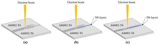
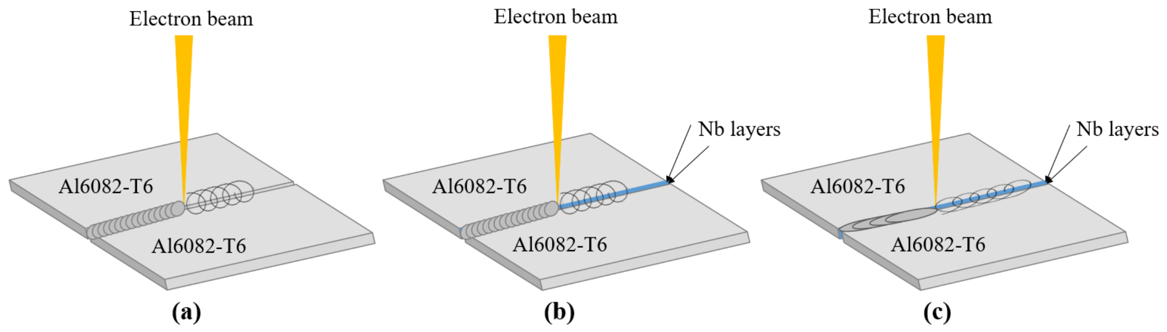
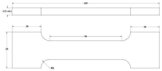
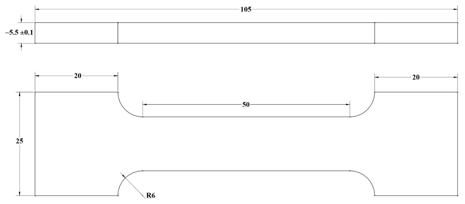
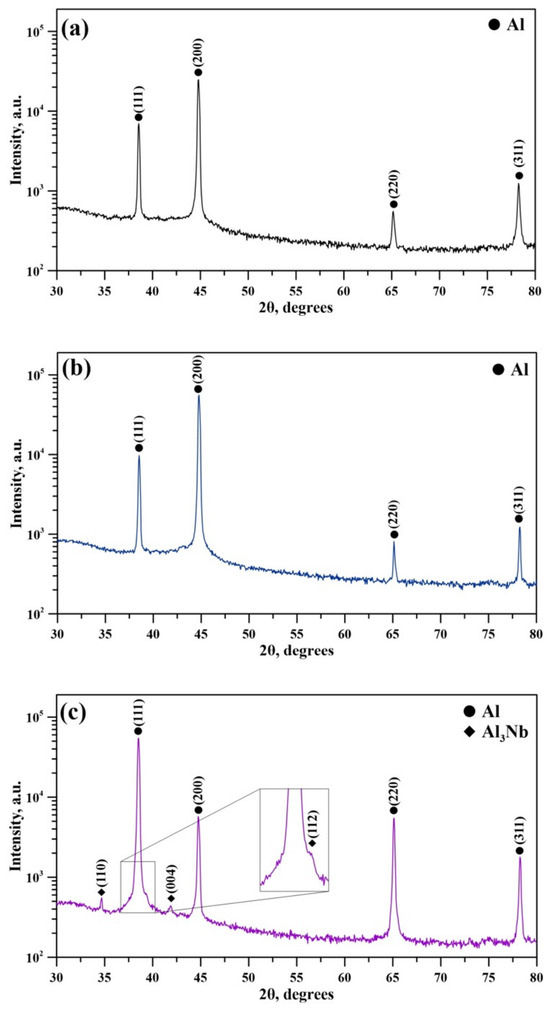
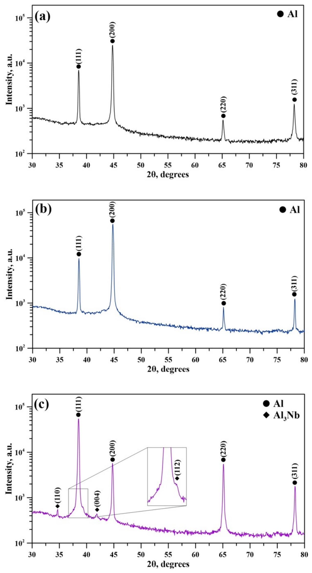
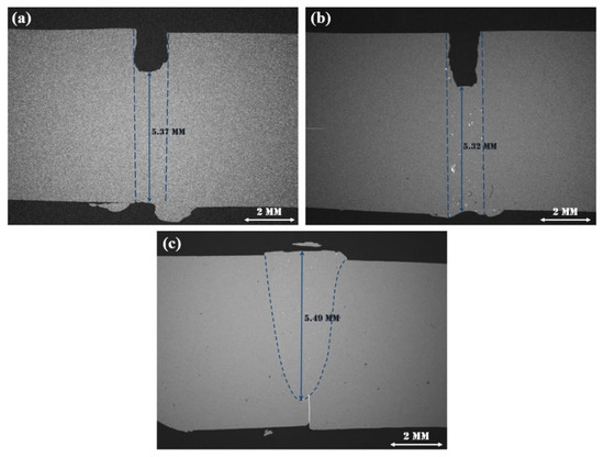
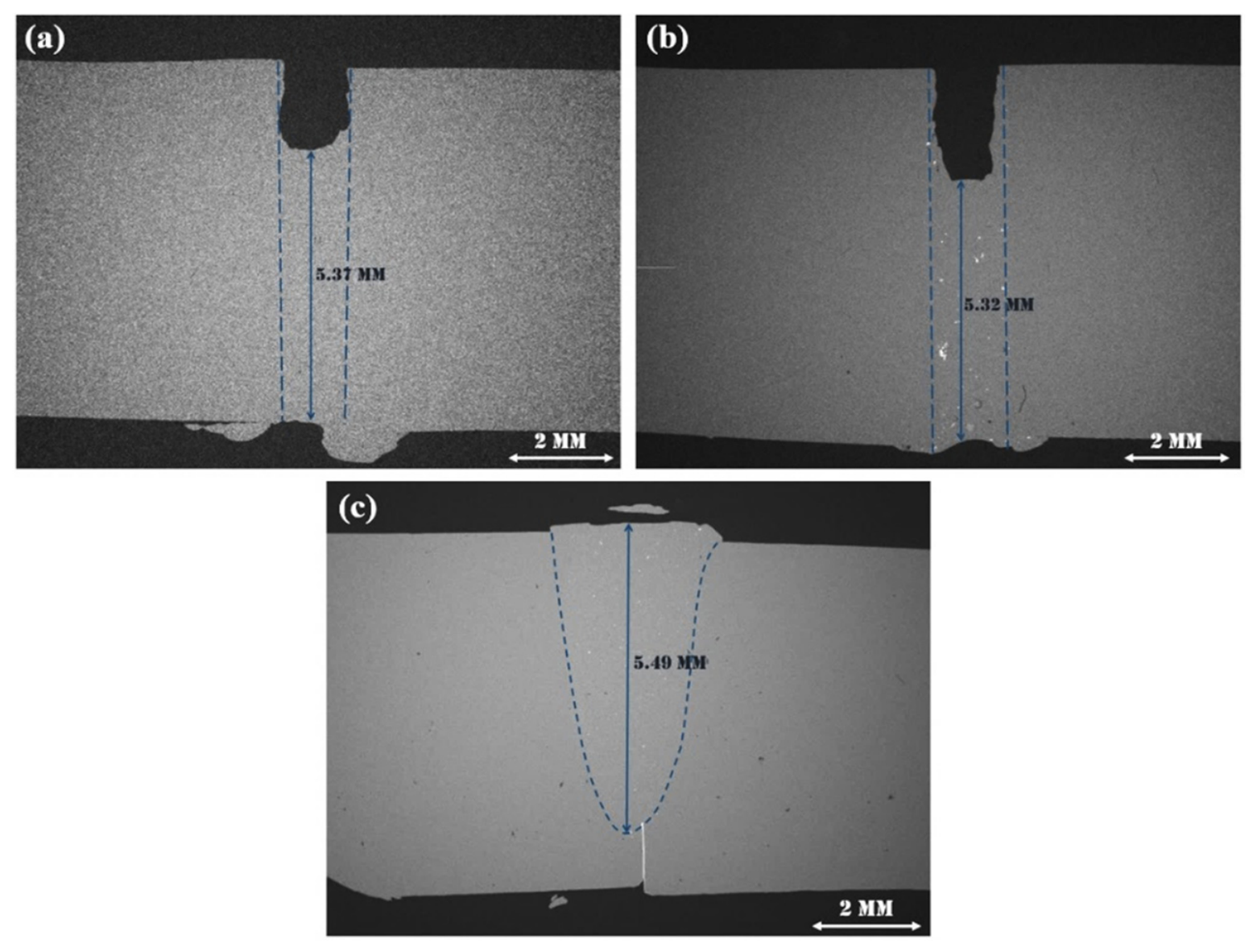
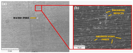
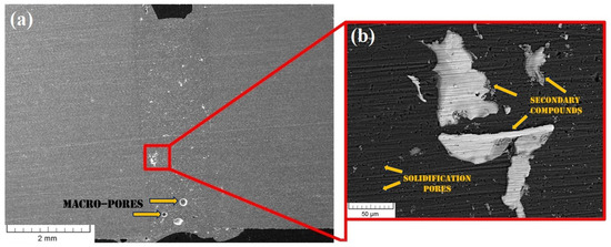
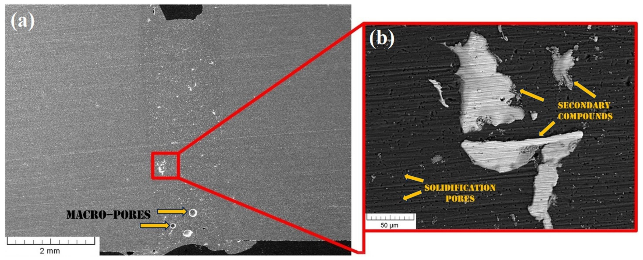
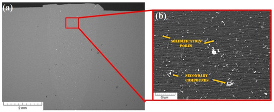
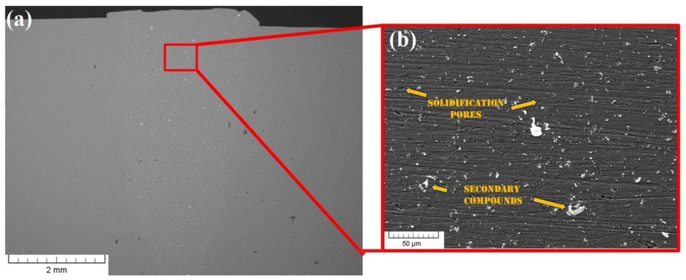
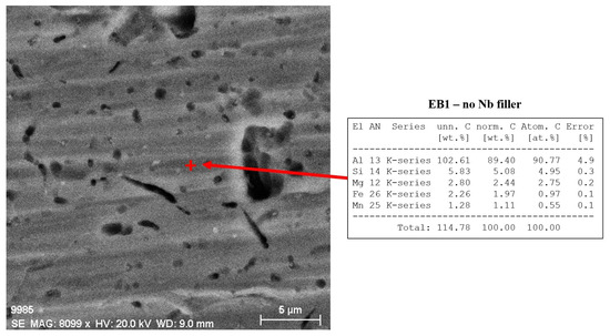
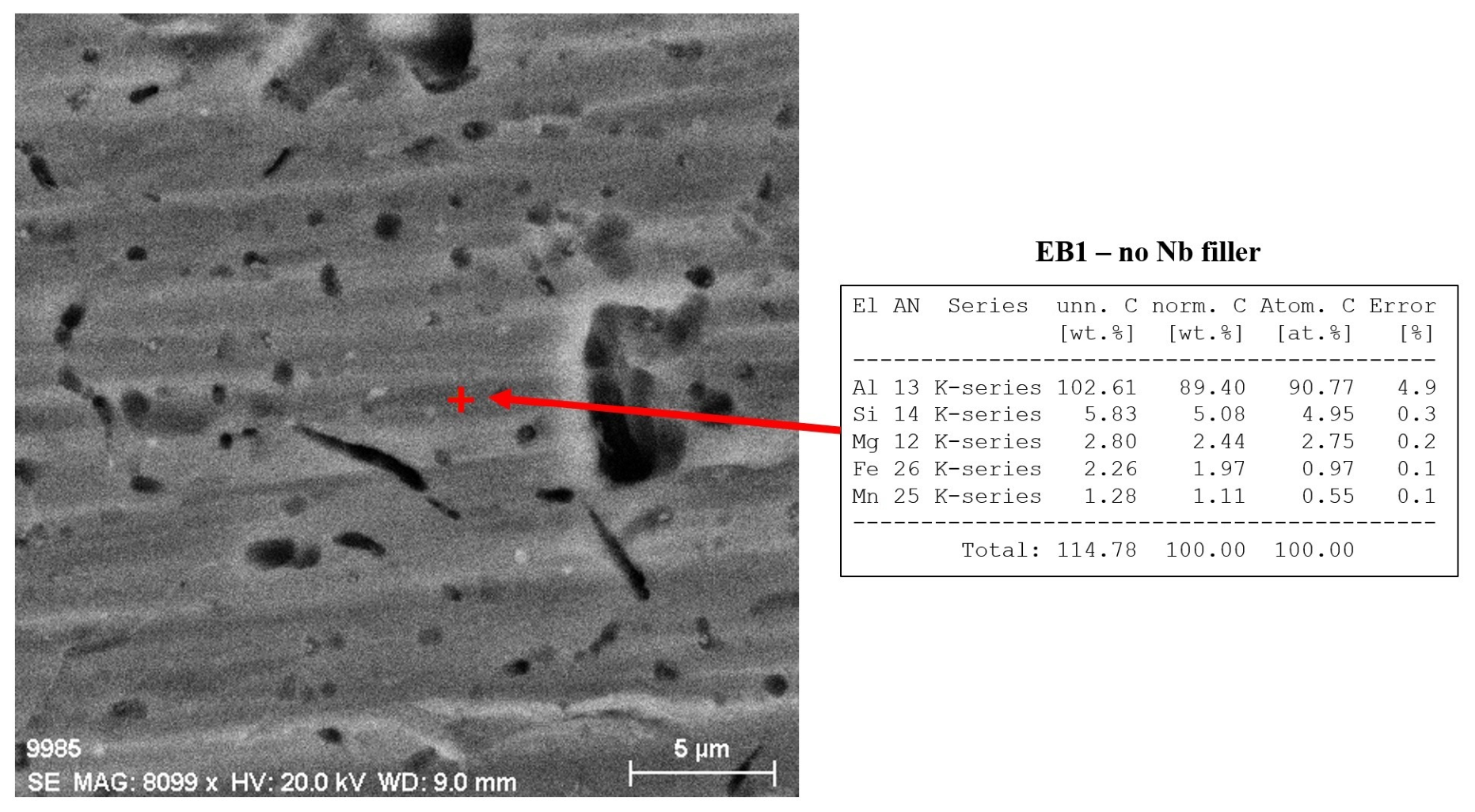
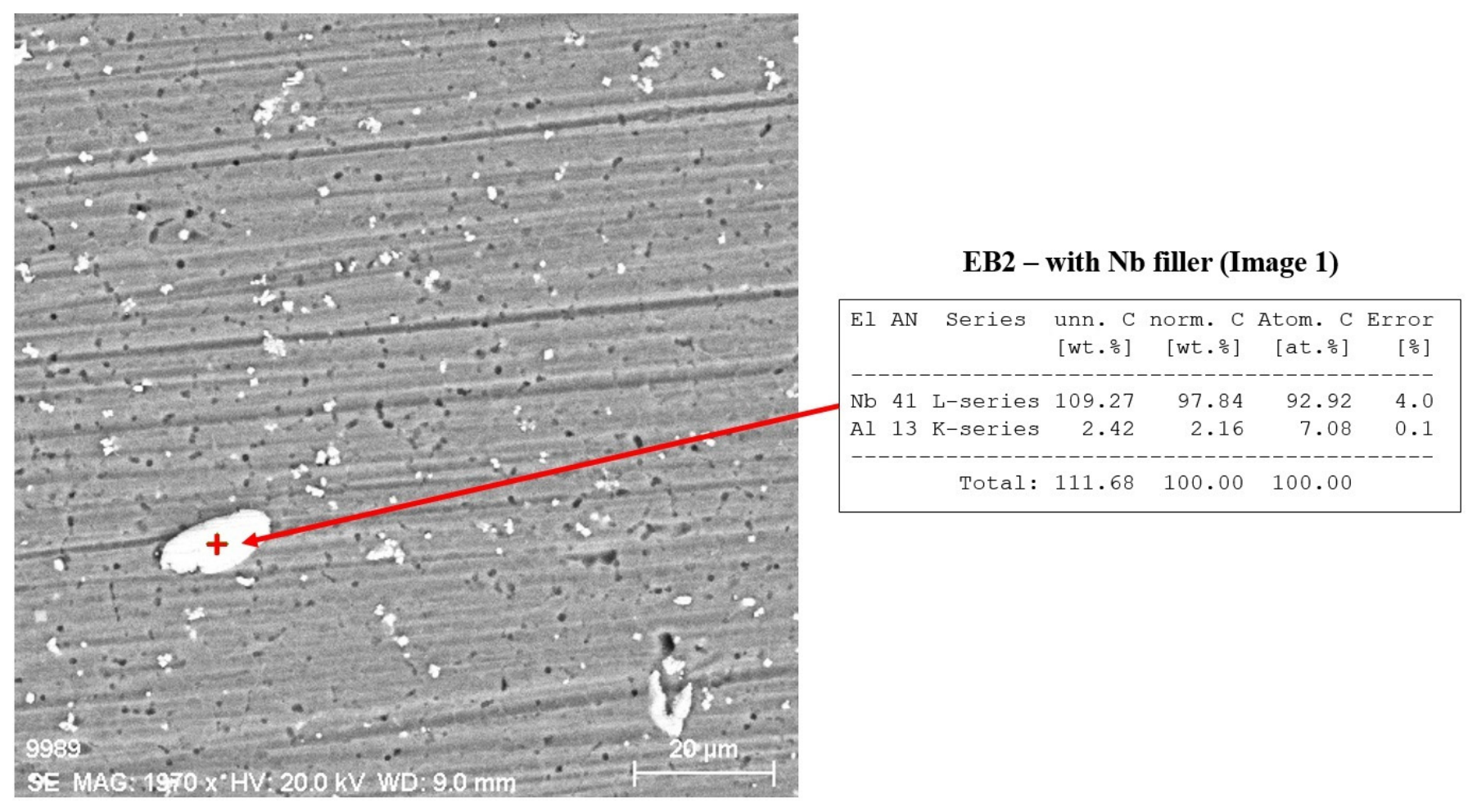
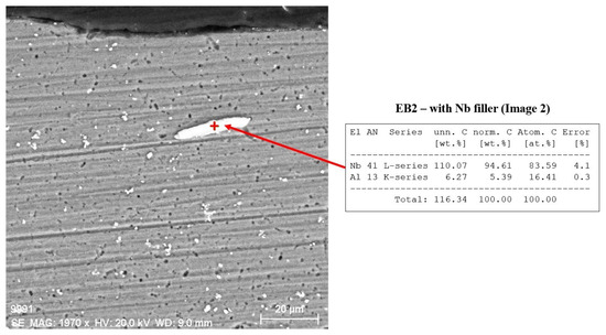
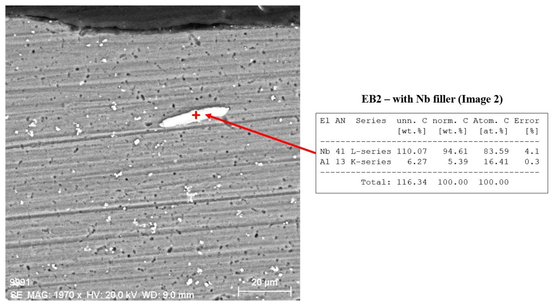
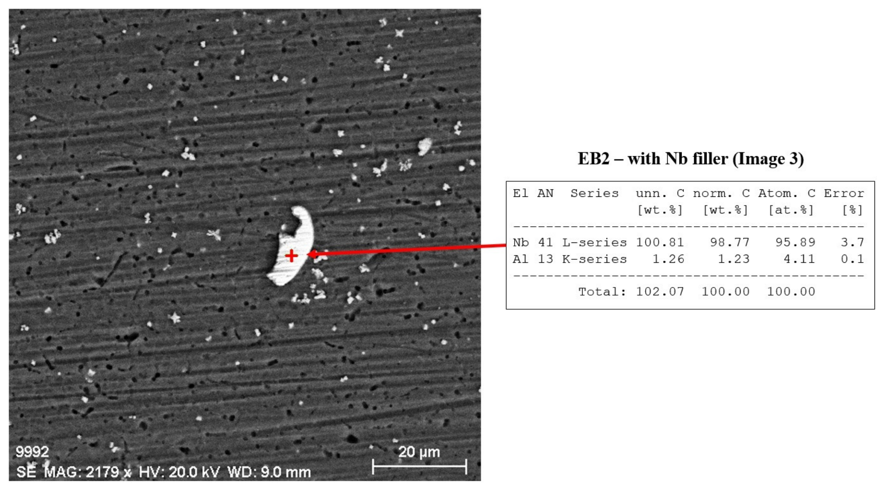
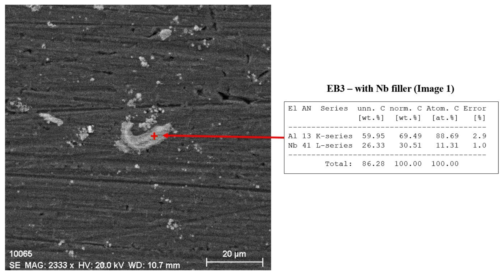
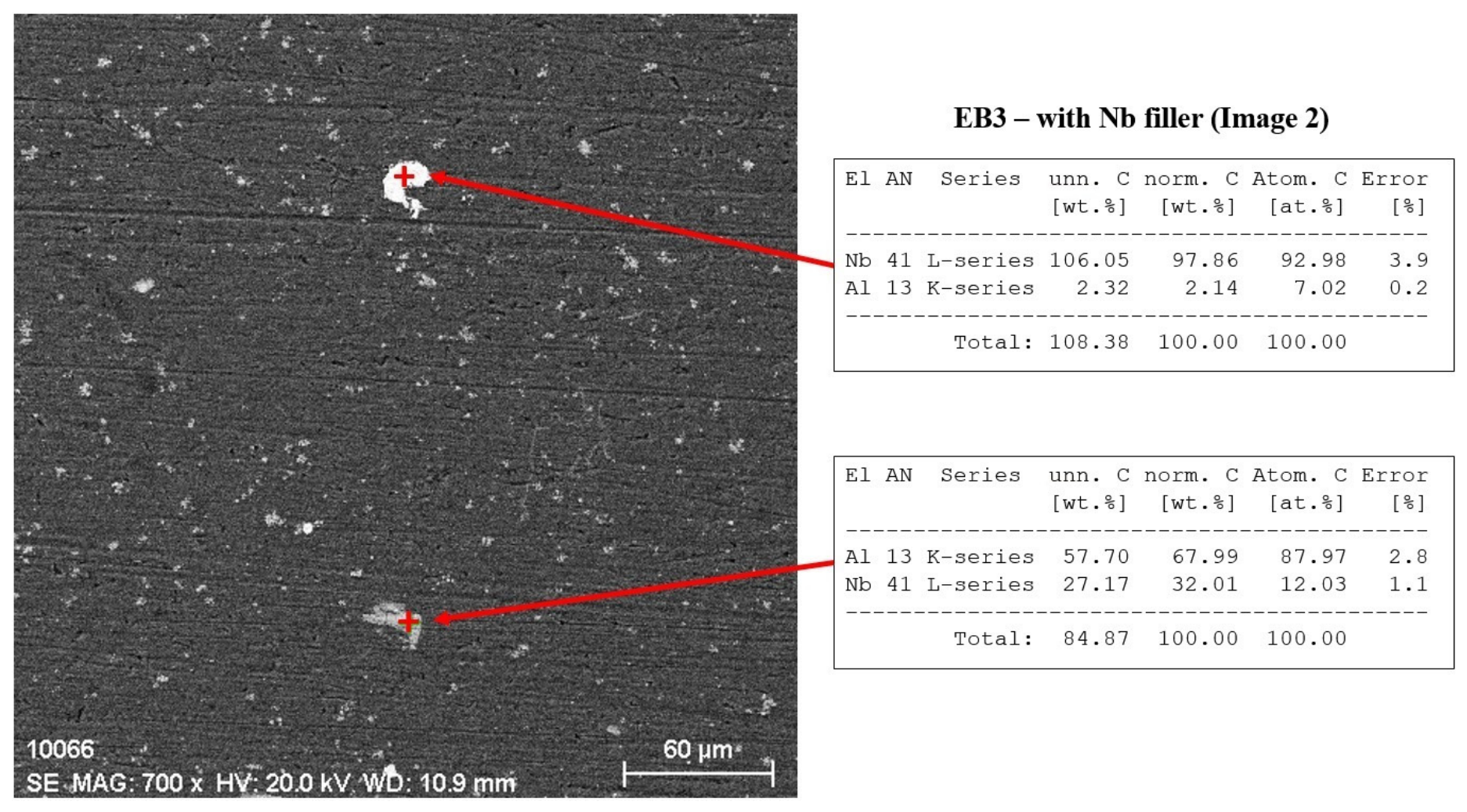
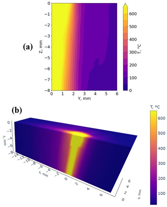
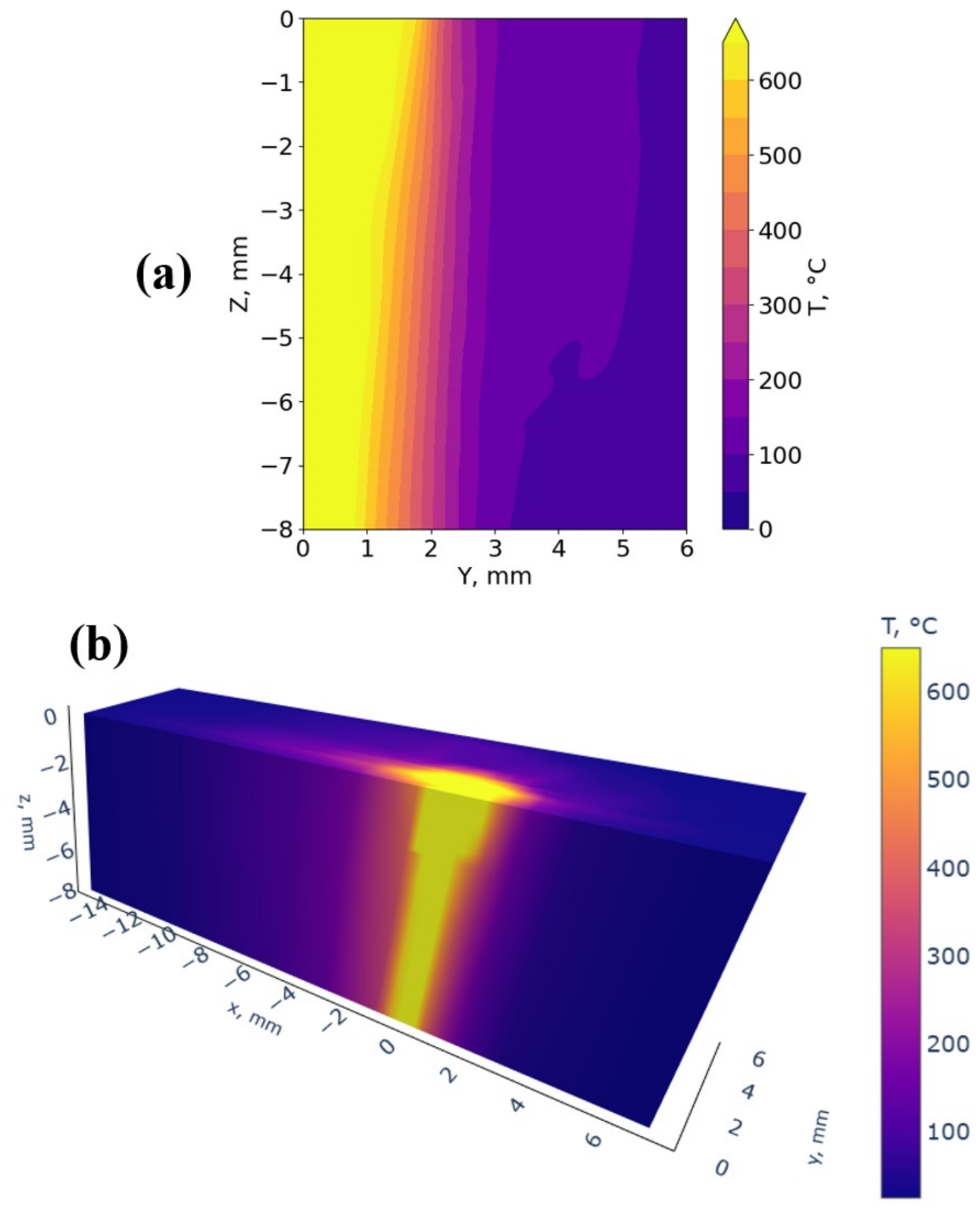
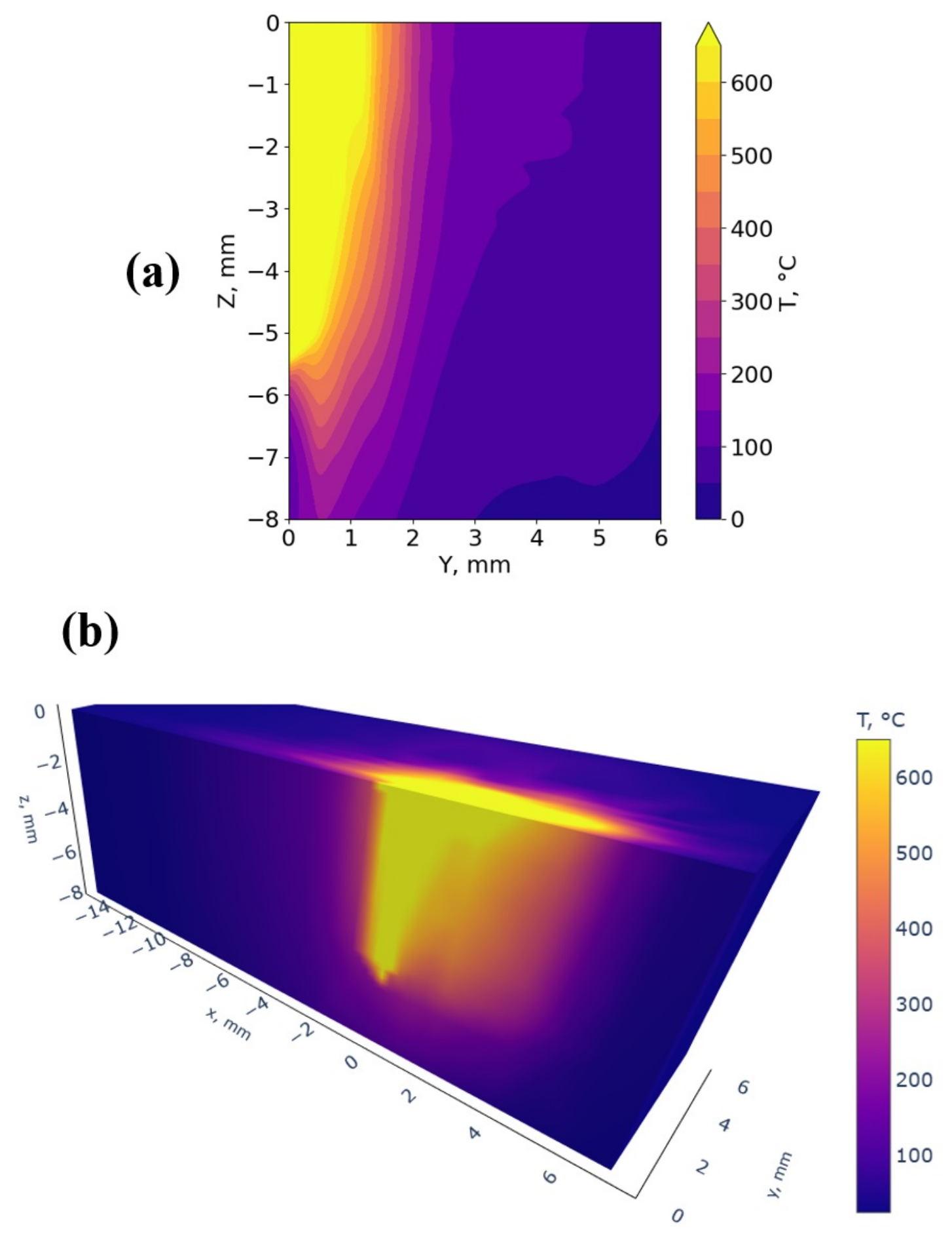

Disclaimer/Publisher’s Note: The statements, opinions and data contained in all publications are solely those of the individual author(s) and contributor(s) and not of MDPI and/or the editor(s). MDPI and/or the editor(s) disclaim responsibility for any injury to people or property resulting from any ideas, methods, instructions or products referred to in the content. |
© 2026 by the authors. Licensee MDPI, Basel, Switzerland. This article is an open access article distributed under the terms and conditions of the Creative Commons Attribution (CC BY) license.