


Abstract
In recent years, an increasing number of national major projects have focused on the physicochemical properties of materials and the structural integrity of components in cryogenic environments. In situ neutron non-destructive testing offers a distinct advantage for scientific research conducted under cryogenic conditions. With the progressive advancement of neutron sources and neutron diffraction techniques, neutron probes have become indispensable for the in situ observation of lattice strain, phase transformation behavior, and residual stresses in materials at cryogenic temperatures. Based on the energy-resolved neutron imaging instrument (ERNI) at Beamline 13 of the China Spallation Neutron Source (CSNS), we have developed a cryogenic loading frame for in situ neutron diffraction tensile tests. This paper presents a detailed description of the mechanical structural design, cooling and control system, strength and thermal analyses, and experimental validation of the device. The apparatus enables in situ neutron diffraction experiments over a wide temperature range of 6–473 K, with an axial loading capacity of 50 kN. Furthermore, the device was employed to conduct in situ neutron diffraction measurements on austenitic 304 stainless steel at both room and cryogenic temperatures. The experimental results confirm that this equipment exhibits stable loading capability and precise temperature control, ensuring the reliability of the experimental data.
1. Introduction
The research and development of materials for extreme environments has always been a bottleneck in the strategic development of countries promoting the global aerospace industry. The study of material performance under low-temperature conditions represents one of the most important and urgent research frontiers. According to experimental research, several high-entropy alloys with single-sided centered cubic phase [1,2,3] exhibit an excellent combination of high strength and ductility under low-temperature conditions, making them highly attractive for engineering and scientific applications under extreme conditions, such as the storage and transportation of liquefied gases (e.g., natural gas and hydrogen), nuclear fusion devices, and outer space exploration [4,5,6]. Engineering development of industrial superconducting composites requires deformation tests at temperatures far below 100 K, as superconductivity in most materials requires ultra-low temperatures. The strain of the superconducting phase in established industrial superconducting materials (such as Nb3Sn composite) can affect the superconducting performance [7,8]. Although traditional materials have demonstrated reliability in practical engineering applications, it is difficult to achieve innovative development of space detectors. In the aerospace field, materials with diverse properties are required to meet varying operational environmental demands, particularly for novel materials lacking prior application validation. Without obtaining the performance parameters of new materials under actual service conditions, it is impossible to accurately determine their design and use. Consequently, new measurement technologies under relevant operational conditions are needed to verify the performance of new materials and determine the usage conditions [9]. Therefore, in situ measurement of material properties under extreme environmental conditions is one of the key research topics.
Neutron sources and neutron diffraction technology have achieved substantial progress, becoming a widely used non-destructive method for measuring stress and strain [10]. Woodruff et al. [9] developed and validated a cryogenic tensile loading apparatus integrated with an engineering neutron diffractometer, enabling in situ stress measurements of structural materials over the temperature range of 10 K to 300 K. Neutrons can penetrate depths of several millimeters, and in some cases even reach several centimeters, thus enabling the detection of the crystal information of large bulk sample represented by polycrystalline samples [11,12]. The Engin-X instrument at the ISIS Neutron and Muon Source in the United Kingdom employs a horizontal single-axis unidirectional tensile device, capable of tensile, compressive, and fatigue testing [13]. The Spectrometer for Materials Research at Temperature and Stress (SMARTS) instrument at Los Alamos National Laboratory in the United States has conducted in situ neutron diffraction experiments on Ni–Ti–Fe shape memory alloys under cryogenic loading, with a loading temperature range of 90–300 K [14]. The Residual Stress Neutron Diffractometer (RSND) at the China Mianyang Research Reactor (CMRR) of the China Academy of Engineering Physics features cryogenic in situ tensile neutron diffraction capability, with a loading temperature range of 6–300 K [15]. Beyond conventional accelerator-based neutron sources, emerging Laser-Driven Neutron Sources (LDNS) have demonstrated unique capabilities for temperature-dependent studies through neutron resonance spectroscopy [16]. These compact sources offer sub-nanosecond pulse durations and high instantaneous flux, enabling time-resolved measurements of lattice dynamics and thermal evolution in materials.
Through neutron diffraction technology, researchers can obtain information such as crystal structure, residual stress, internal strain, and phase fractions. Due to the fact that low-temperature extensometers can only provide the average strain of materials, this restricts the study of deformation characteristics of materials at low temperatures. Therefore, based on the physical design of ERNI, we designed a Cryogenic Loading Frame for in situ Neutron Diffraction Tests (CLFINDT) in order to study the mechanical properties of low-temperature materials. The CLFINDT enables loading across a wide temperature range, with a minimum temperature of 6 K, and is compatible with spallation neutron sources. The temperature range of the clamping head is from 6 K to 473 K, which is currently the first equipment with a wide temperature range for spallation neutron sources in China [17]. This broad operational temperature window satisfies the requirements of most cryogenic tensile testing applications. The present article provides a detailed exposition of the apparatus design and presents representative test results.
2. Composition and Design of CLFINDT
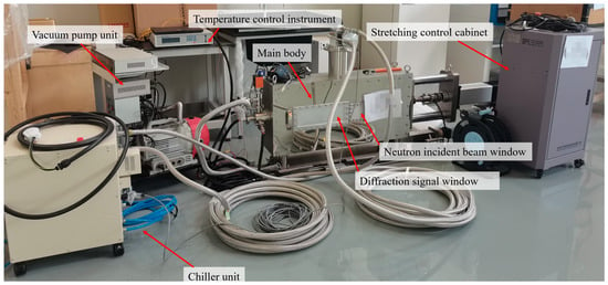
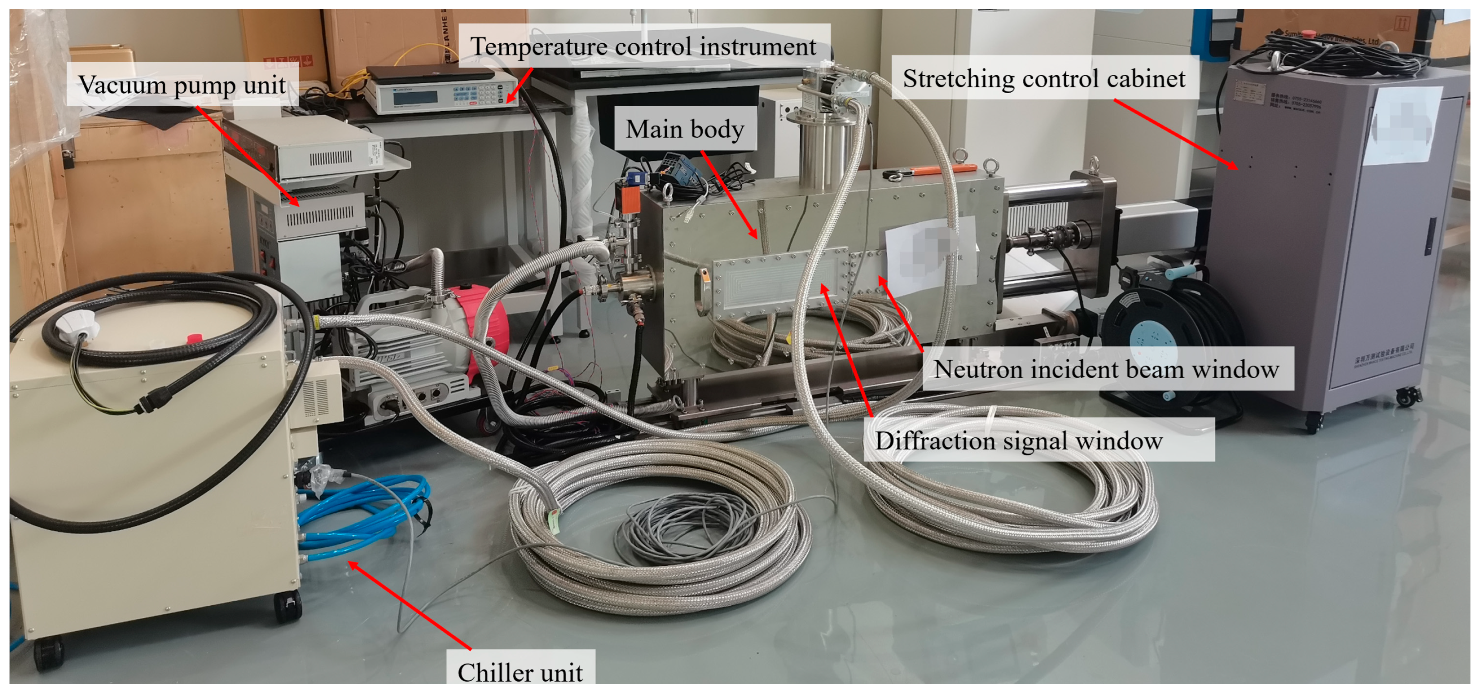
The CLFINDT consists of a loading machine system and a low-temperature system, with two working modes: one is the room temperature mode, which controls the loading machine to stretch the sample at room temperature; the other is the low-temperature coupling mode, which controls the vacuum chamber and the low-temperature chamber of the sample to stretch the sample under a certain temperature field environment, aiming to study the service performance of materials under low-temperature conditions. The operational component of the equipment is shown in Figure 1, including the main body of the equipment, vacuum pump unit, chiller unit, temperature control instrument, and loading control cabinet. After the sample is installed in place, the vacuum pump unit vacuums the cavity, and then uses a cold head to cool the sample or a heating block to heat the sample to meet the temperature loading requirements. The chiller unit provides the required cooling capacity for the operation of the cold head equipment, and temperature control and feedback are the responsibility of the temperature control instrument. Finally, the loading control cabinet is used to achieve tensile stress loading of the sample. The combination of the outer shell of the cavity and the sealing surface forms a sealing structure, which can ensure that the interior is in a vacuum environment to avoid condensation of the sample rod or cold screen at low temperatures. The design of adding a cold screen inside can further physically isolate the heat loss of the sample. The temperature control instrument can collect feedback from four temperature sensors vertically for monitoring temperature changes, and can also calibrate different sample temperatures. Due to the unidirectional tensile stress loading of the equipment, reverse displacement compensation will be applied to the sample during the experiment, which is controlled by the bottom grating ruler, motor controller, and programmable logic controller (PLC). The stretching loading, two-dimensional motion control console, and temperature measurement system are respectively connected to the local cabinet and temperature control instrument to achieve coordinated logical control of temperature and motion. The system can communicate with the central IPC of the ERNI through a switch (device communication line) to achieve the neutron in situ diffraction experimental operation of the sample.
Figure 1.
The operational components of the loading machine.
This low-temperature equipment is mainly composed of a tensile testing machine and a cryogenic control system, as shown in Figure 1. Specific components include the equipment main body, vacuum pump unit, chiller unit, temperature control instrument, and tensile control cabinet. When conducting cryogenic tensile tests, the vacuum pump unit is first used to evacuate the chamber. When the chamber pressure reaches approximately 10 Pa, the residual gas is reduced to roughly 0.01% of its initial amount. Then the molecular pump is activated, leading to a dramatic decrease in pressure. At the same time, the cooling head is powered on. As the cooling head temperature drops, the vacuum improves markedly, with the chamber vacuum becoming progressively better. During this process, according to the thermal convection formula presented later in the paper, the gas effect is negligible. When the vacuum reaches 10−3 Pa, the sample will reach its ultra-low temperature. The chiller unit provides the cooling capacity required for operating the cooling head equipment, while temperature control and feedback are managed by the temperature control instrument. When the temperature at the sample clamping end drops below the test temperature, the target temperature is set using a computer to bring the sample temperature into alignment. The heating head and cooling head at both ends of the sample form a closed-loop control system to maintain dynamic thermal equilibrium of the test temperature of the sample. Once the target temperature is reached, a tensile test program is configured via the computer, and the tensile test is conducted.
2.1. Structure Design
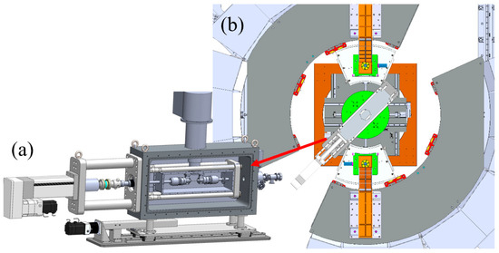
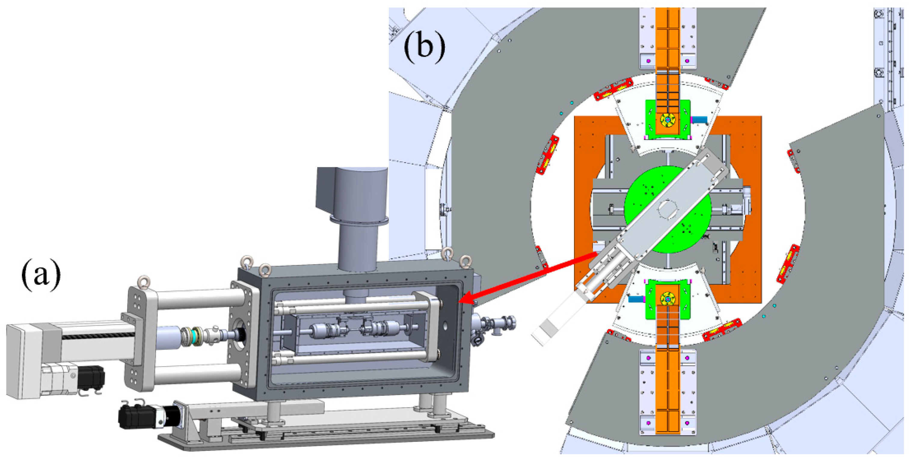
The CLFINDT is placed on the sample stage lifting system of the neutron instrument, and the center of the loading machine’s sample can be adjusted to coincide with the beam through lifting and lowering. As shown in Figure 2, the space limitation of the loading device placed on the sample stage is shown. During the in situ diffraction experiment, a fine collimator will be installed before the 90° detector bank. Due to the installation space required for the fine collimator, there are requirements for the width dimension of the loading machine. For the coverage angle of the fine collimator, the width of the loading machine cannot exceed 230 mm.
Figure 2.
Installation diagram of key components of ERNI: (a) the CLFINDT, (b) the CLFINDT is placed on the sample stage.
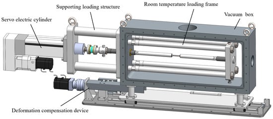
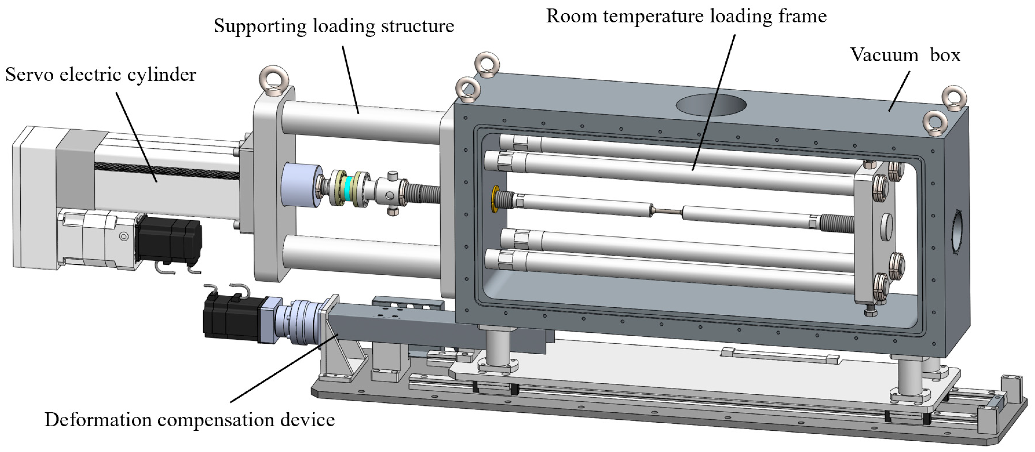
As shown in Figure 3, the loading machine system is mainly composed of a servo electric cylinder, loading frame, ambient temperature fixture, vacuum box, and deformation compensation device. The main frame is made of stainless steel. The maximum load for tensile stress loading is 50 kN. Since the tension is unidirectional, the sample is stretched in one direction, leading to a deviation of the sample center from the beam center. The deformation compensation device is operated to compensate for the displacement during the in situ experiment.
Figure 3.
Schematic diagram of the loading machine system structure.
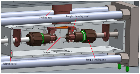
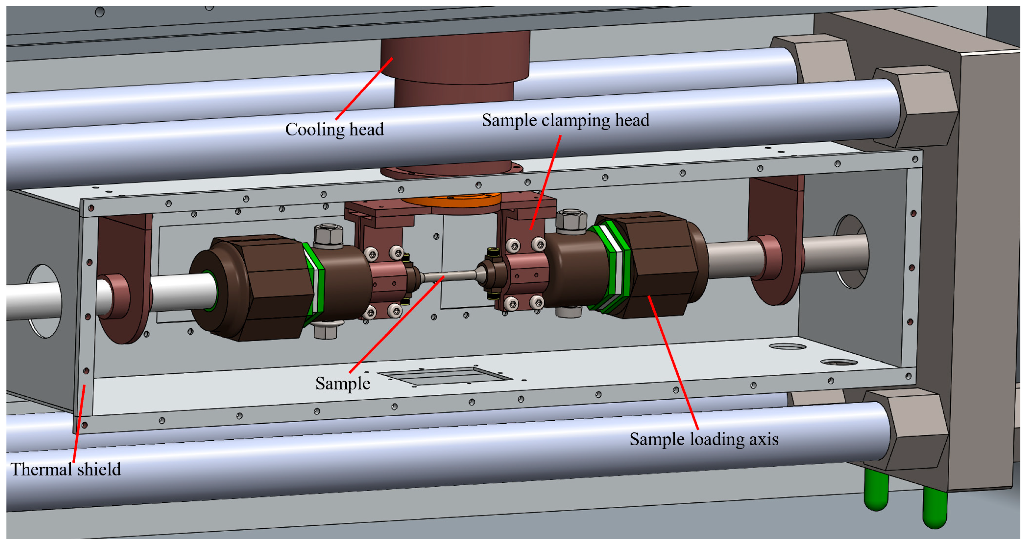
The low-temperature system is mainly composed of a cooling head, a sample clamping head, a sample loading shaft, a cooling screen, and a vacuum seal, as illustrated in Figure 4. The temperature control range at the clamping head is 6~473 K. A cooling shield is used to physically isolate the sample from the vacuum chamber and maintain temperature stability in the sample area. The cavity is sealed with an O-ring, with a vacuum degree of 1.0 × 10⁻³ Pa. The temperature control cable is connected to the atmosphere and vacuum through an aviation connector.
Figure 4.
Schematic diagram of low-temperature system structure.
2.2. Temperature Analysis
Heat transfer is a common phenomenon in nature. Due to temperature differences in or between media, heat will spontaneously transfer from one part of the system to another. According to different heat transfer modes, heat transfer modes are divided into heat conduction, heat convection, and heat radiation [18].
- (1)
- Thermal conduction is the main way of heat transfer in solids and also the main cooling method of this project, which is the way heat is transferred from the higher temperature part of an object to the lower temperature part [19]. The calculation formula is
In the formula, q represents the heat flux density, measured in W/m2; Δt represents the temperature difference between objects, measured in K; Rt represents the thermal resistance per unit area of an object, measured in (m2·K)/W.
- (2)
- Thermal convection refers to the process of energy transfer in a fluid, mainly caused by the relative displacement of particles and the transfer of heat. The medium of heat transfer can be gas or liquid. In this study, thermal convection mainly refers to the presence of a very small amount of air in a vacuum chamber, and its calculation formula is
In the formula, q represents the heat flux density, measured in W/m2; M represents the fluid mass per unit area per unit time, measured in kg/(m2·s); cp represents the specific heat capacity of the flowing medium, measured in J/(kg·K); t represents temperature, measured in K.
- (3)
- Thermal radiation, which is transmitted by an object emitting electromagnetic waves due to its temperature, is one of the heat loss modes in the vacuum chamber of this project. The higher the temperature, the greater the total energy radiated. Its calculation formula is
In the formula, E represents the amount of heat radiated from the surface of an object per unit area to the outside world per unit time, measured in W/m2; ε represents the emissivity coefficient of the object surface, ranging from 0 to 1; σ represents the Stefan–Boltzmann constant or blackbody radiation constant, i.e., W/(m2·K4); T represents the temperature of an object, measured in K.
Structural design was carried out through formula derivation and simulation calculations. In order to ensure the rationality of the equipment model structural design and meet the requirements of in situ sample experiments for temperature control, structural optimization design was carried out for the heat conduction structure, as shown in Figure 5. This system comprises insulation components, heat conduction components, heating blocks, sample clamping heads, and samples. The design elements are as follows:
- (1)
- The cavity is made of stainless steel, with a stable vacuum level, high strength, and minimized heat loss. Heat transfer occurs exclusively through contact conduction and radiation.
- (2)
- The heat exchange efficiency between the heat-conducting components and the clamping head is high enough to effectively reduce the heat loss between them and maintain isothermal conditions.
- (3)
- The thermal insulation component consists of a cryogenic screen directly coupled to the secondary cold head, providing physical isolation for the vacuum chamber with less heat loss.
- (4)
- All interfaces contact properly while satisfying machining accuracy specifications.
- (5)
- The temperature outside the sealed shell is maintained at room temperature.
Figure 5.
Schematic diagram of the cooling structure and its physical photos: (a) cooling head, (b) cooling plate, (c) soft conductive cold strip, (d) secondary copper hoop, (e) sample.
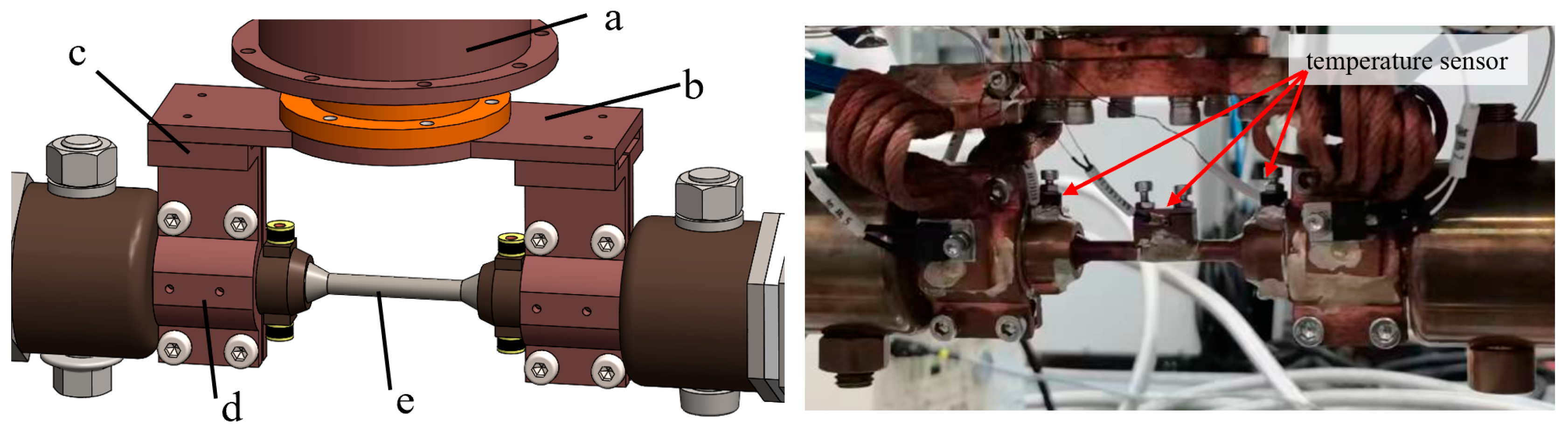
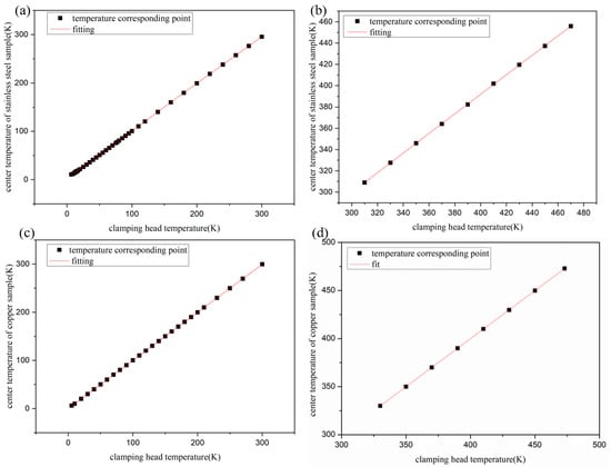
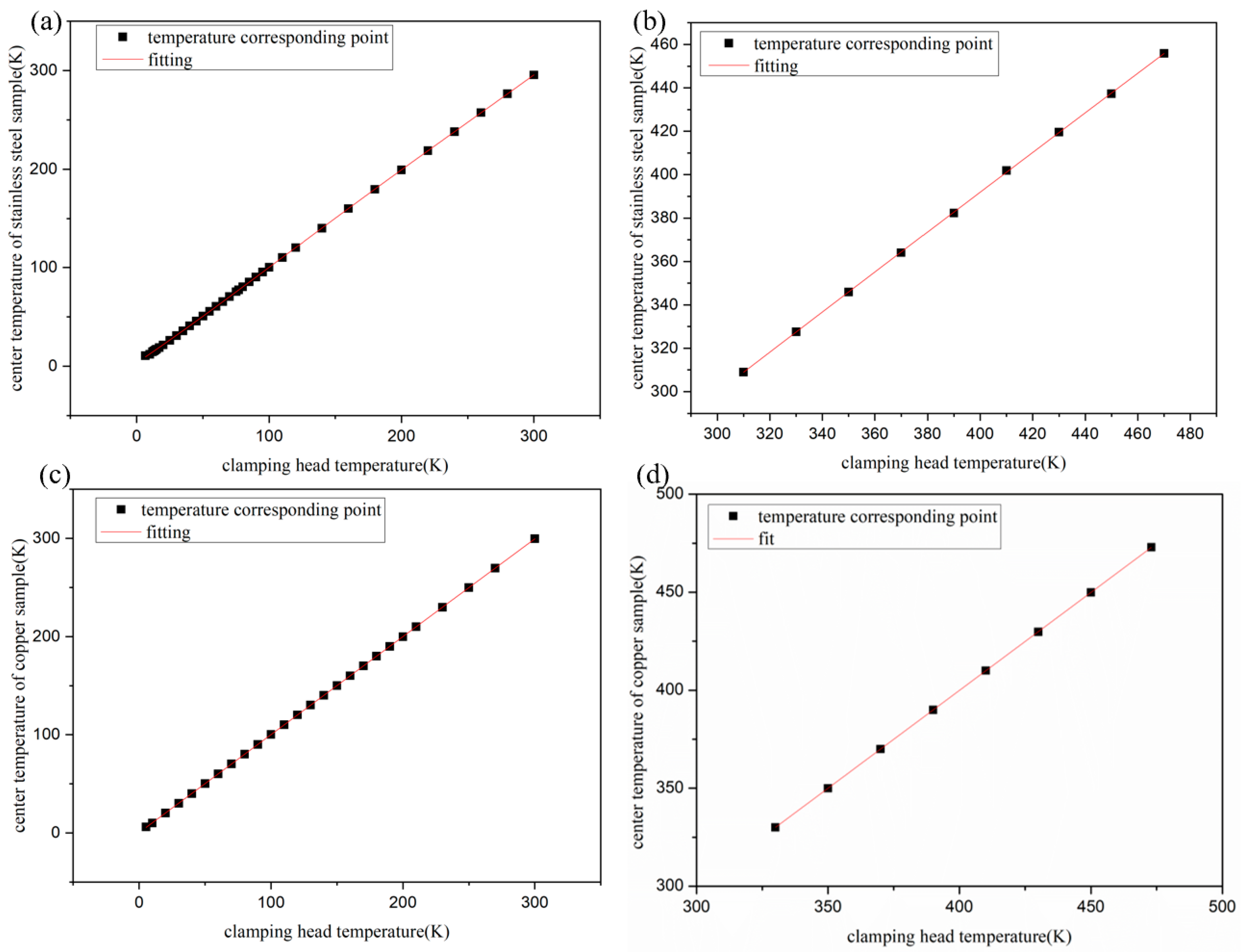
Accurately measuring the temperature of both the clamping head and the sample is crucial, particularly during low-temperature heating processes, to prevent temperature overshoot that could compromise or damage the experimental results. During in situ neutron diffraction measurements under tensile loading, it is difficult to directly monitor the sample temperature in real time. As an alternative approach, the temperature at the sample center is extrapolated from measurements at the clamping head. In order to precisely analyze the correlation between the temperature at the two clamping heads and the sample center, the temperature at key positions was systematically measured. Figure 6 shows the temperature curves of the sample under vacuum conditions. The temperature correlation between the sample’s center (copper/S30403) and the clamping head was experimentally established, enabling precise thermal control in subsequent in situ neutron diffraction experiments.
Figure 6.
Temperature measurement data and fitting diagram of stainless steel and copper samples: (a) low-temperature data of stainless-steel sample, (b) high-temperature data of stainless-steel sample, (c) low-temperature data of copper sample, (d) high-temperature data of copper sample.
3. Test Result
3.1. Mechanical Properties
According to the national standard GB/T228.1-2021 [20], specimens are classified into proportional specimens and non-proportional specimens. Proportional specimens refer to specimens whose original gauge length L0 is proportional to the square root of their cross-sectional area S0, denoted as k, which is a constant; non-proportional specimens refer to specimens whose original gauge length L0 is independent of their original cross-sectional area S0. The sample type of the small tensile testing machine designed for deep vacuum and low temperature in this project adopts short samples from non-proportional specimens. The original gauge length L0 of the sample is preliminarily determined to be 50 mm, and its cross-sectional area S0 can be obtained as 28.3 mm2 from the formula for the area. Calculate the maximum load force required to break the specimen using the following formula
In the formula, F represents the maximum load force required by the loading device to break the specimen, in N; n represents the safety factor, where n = 1.2 is selected; σb represents the tensile strength of the tensile material, measured in MPa; S represents the cross-sectional area of the tensile specimen within the parallel segment, measured in mm2.
According to the national standard GB/T6397-1986 [21], a circular specimen with a diameter of 6 mm is used as the design standard. The material of the specimen selected for debugging is stainless steel S30403. According to the national standard GB/T1220-2007 [22], the tensile strength σb is taken as 520 MPa (minimum value), and the cross-sectional area S0 is 28.3 mm2. The formula above calculates F = 17,659.2 N. The maximum tensile force of the tensile device designed in this project is F = 50 kN.
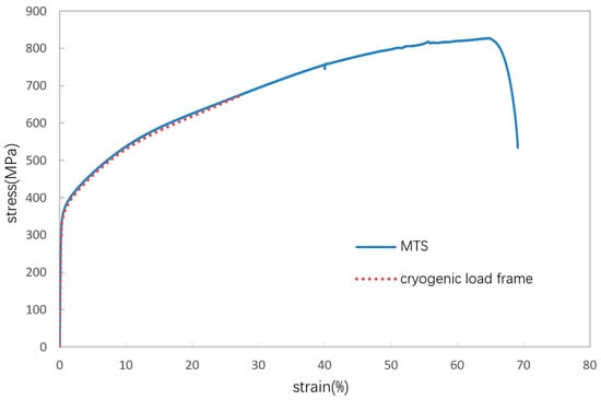
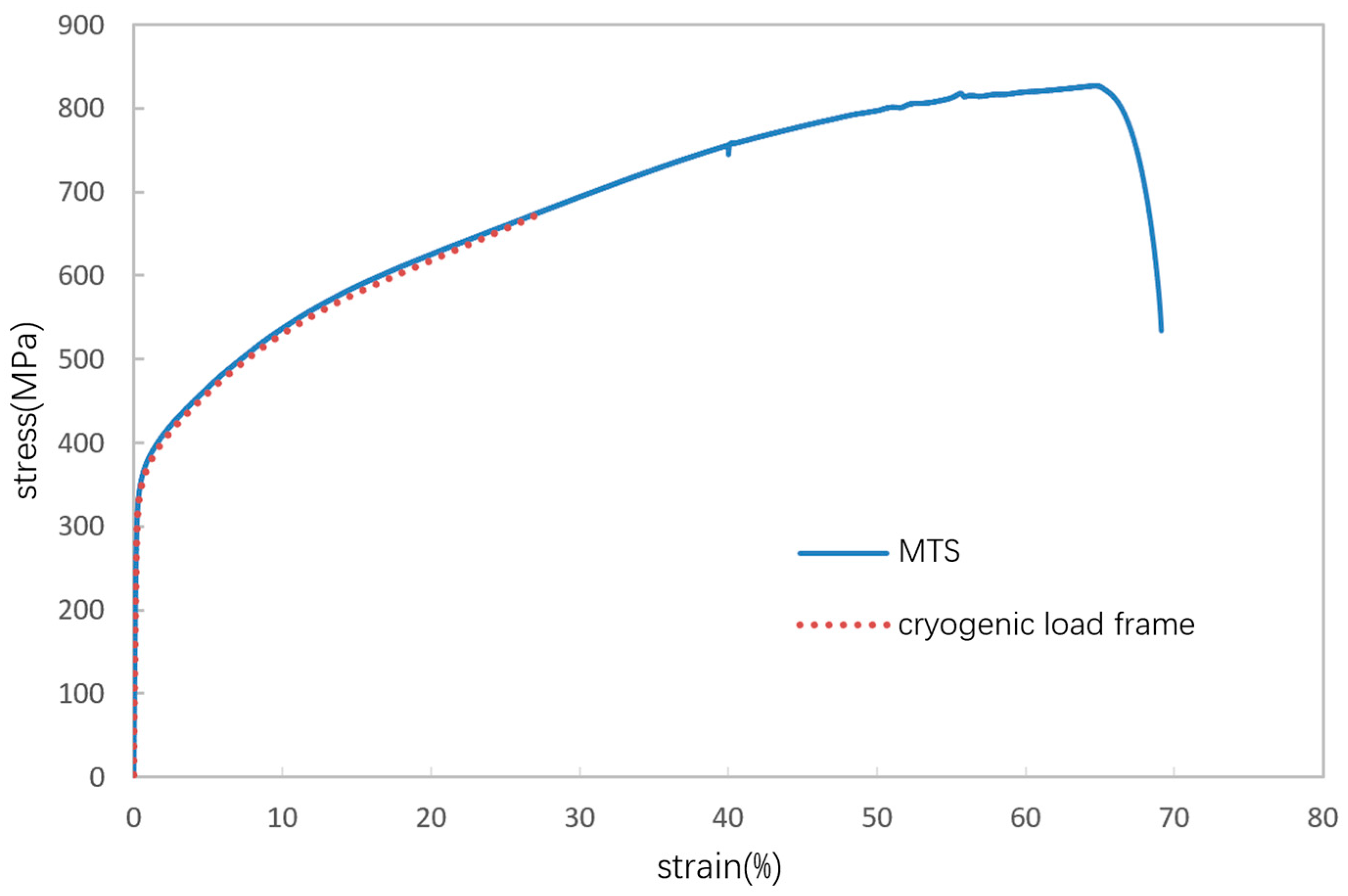
Tensile tests were conducted on S30403 stainless steel specimens at room temperature. The stress–strain curves were recorded by an extensometer during deformation. Parallel tests were performed on identical specimens using a Mechanical Testing and Simulation (MTS) loading machine within our research group. The specific tensile results are presented in Figure 7.
Figure 7.
Comparison of stress–strain results from the cryogenic load frame and MTS loading machine after stretching.
The tensile test results obtained from our cryogenic load frame demonstrate good agreement with those from the MTS loading machine. The tensile device developed in this research demonstrated comparable performance to the leading commercial systems at room temperature, and the design fulfills the experimental requirements.
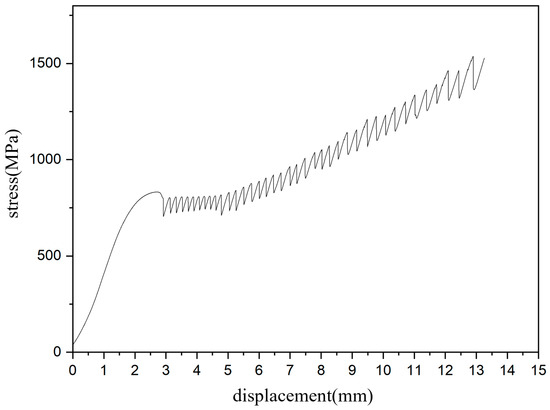
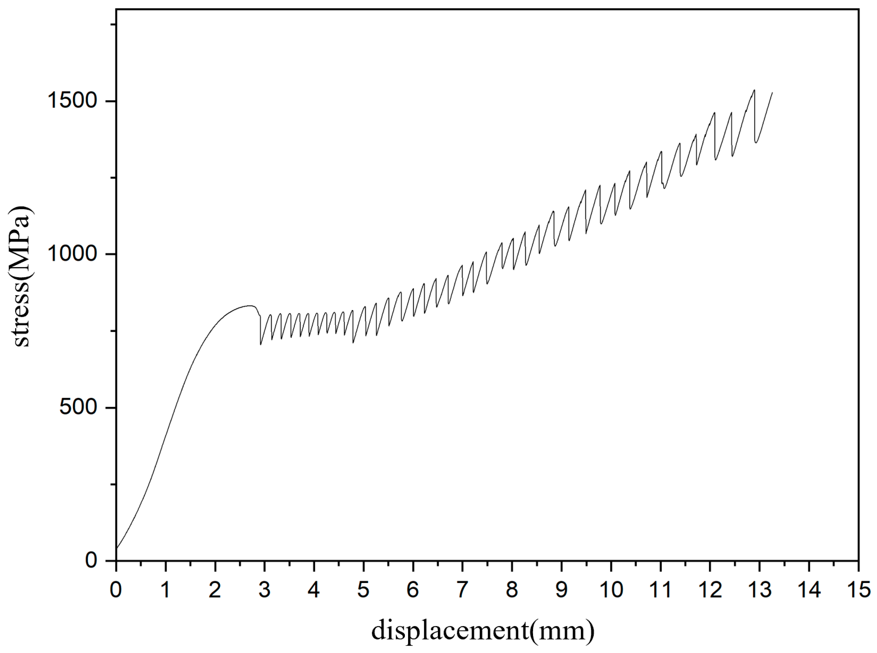
When the tensile device was cooled to its minimum operating temperature, the specimen temperature stabilized at 11 K through the calibrated sensors of the clamping head. Uniaxial tensile testing on the S30403 stainless steel sample was performed under displacement control with a constant rate of 0.2 mm/min. As shown in Figure 8, stress-displacement curves of the S30403 stainless steel exhibit serrated flow at 11 K. This behavior is consistent with the cryogenic tensile characteristics specified in GB/T228.4-2019 [23] “Tensile Testing of Metal Materials Part 4: Liquid Helium Test Method”. Additionally, similar behavior appears in existing low-temperature tensile tests on stainless steel [24,25], which arises from unstable plastic deformation and repeated resistance impact. Therefore, the cryogenic tensile testing system developed in this research meets the requirements of ultra-low-temperature deformation in the vacuum deep low-temperature zone.
Figure 8.
Engineering stress-displacement curves of austenitic 304 stainless steel at 11 K obtained using the in situ loading machine.
3.2. Neutron In Situ Diffraction Experiment
Neutron diffraction serves as an important means for studying the mechanical properties of engineering materials. The fundamental principle underlying the measurement of residual stress relies on interplanar spacing determined by neutron diffraction to serve as atomic strain gauges for characterizing stress distributions within a sample. Specifically, internal stress in a material induces corresponding lattice strain, which subsequently causes shifts in Bragg peaks observed in diffraction patterns. The principle of determining lattice strain is based on Bragg’s law:
where λ is the neutron wavelength, d is the interplanar spacing, and θ is the diffraction angle [26]. The lattice strain can be determined by calculating the change in the observed reflections:
where is the lattice spacing of the strain/stress free sample [27].
λ = 2dsinθ
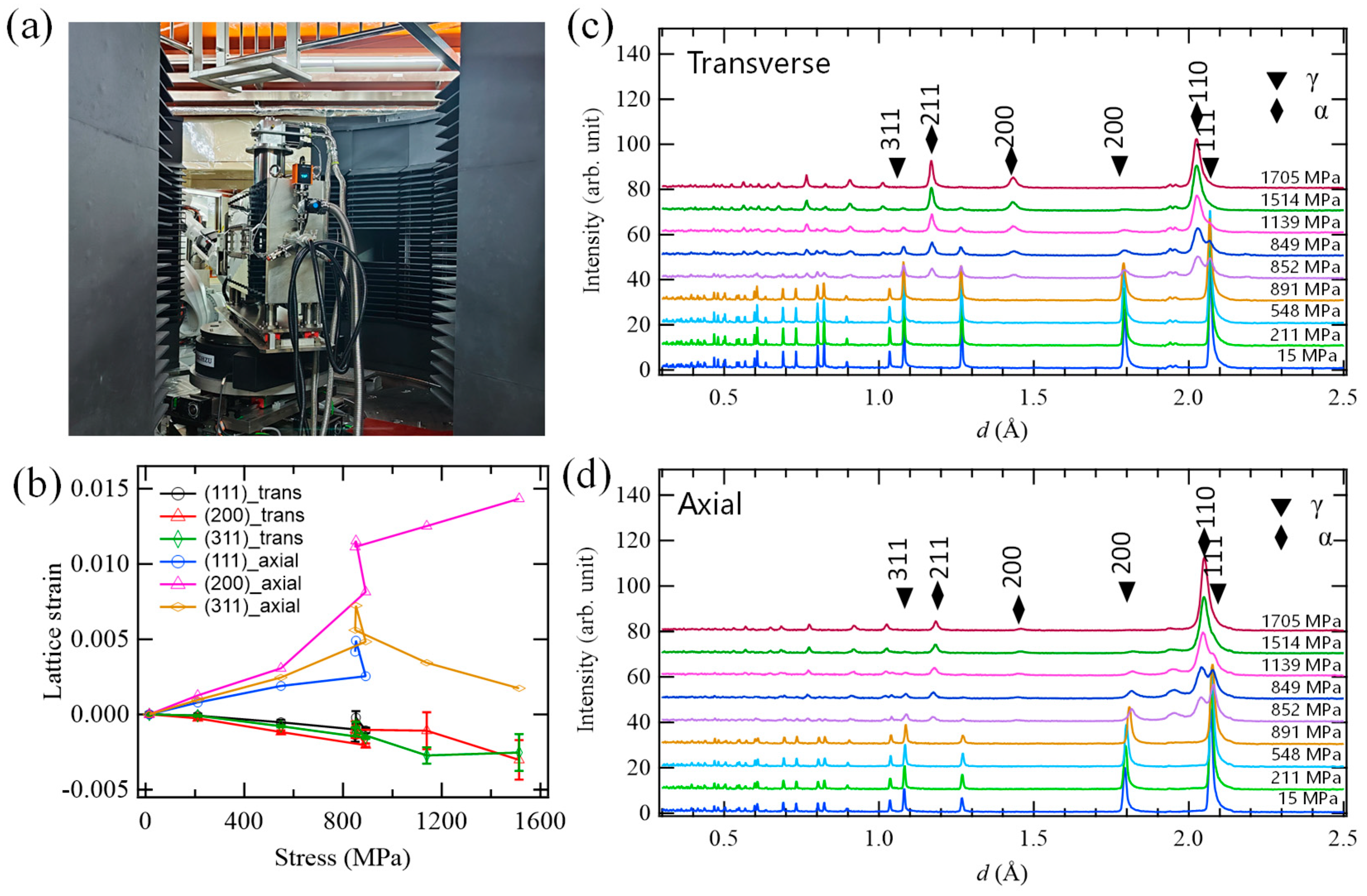
To evaluate the performance of the cryogenic loading frame, in situ neutron diffraction tensile experiments were conducted at ERNI. The experimental setup is shown in Figure 10a. The samples were stainless steel S30403 rods with a diameter of Ø 6 mm and a gauge length of 40 mm. The tensile loading experiments were performed at 297 K and 10 K, respectively. The measurement time for each test was 25 min at a proton beam power of 155 kW at CSNS. The neutron beam size for the ND experiments was limited to 10 mm × 10 mm by using an incident beam slit. The neutron wavelength of 0.1–4.2 Å was selected by the chopper system. A schematic diagram of the experiment for in situ tensile neutron diffraction measurement is shown in Figure 9. The incident neutron beam passes through two aluminum windows, namely a vacuum box and a cold screen, and then directly reaches the central area of the sample. After passing through the aluminum windows, the diffracted neutrons finally arrive at the detectors.
Figure 9.
Schematic diagram of in situ tensile neutron diffraction experiment.
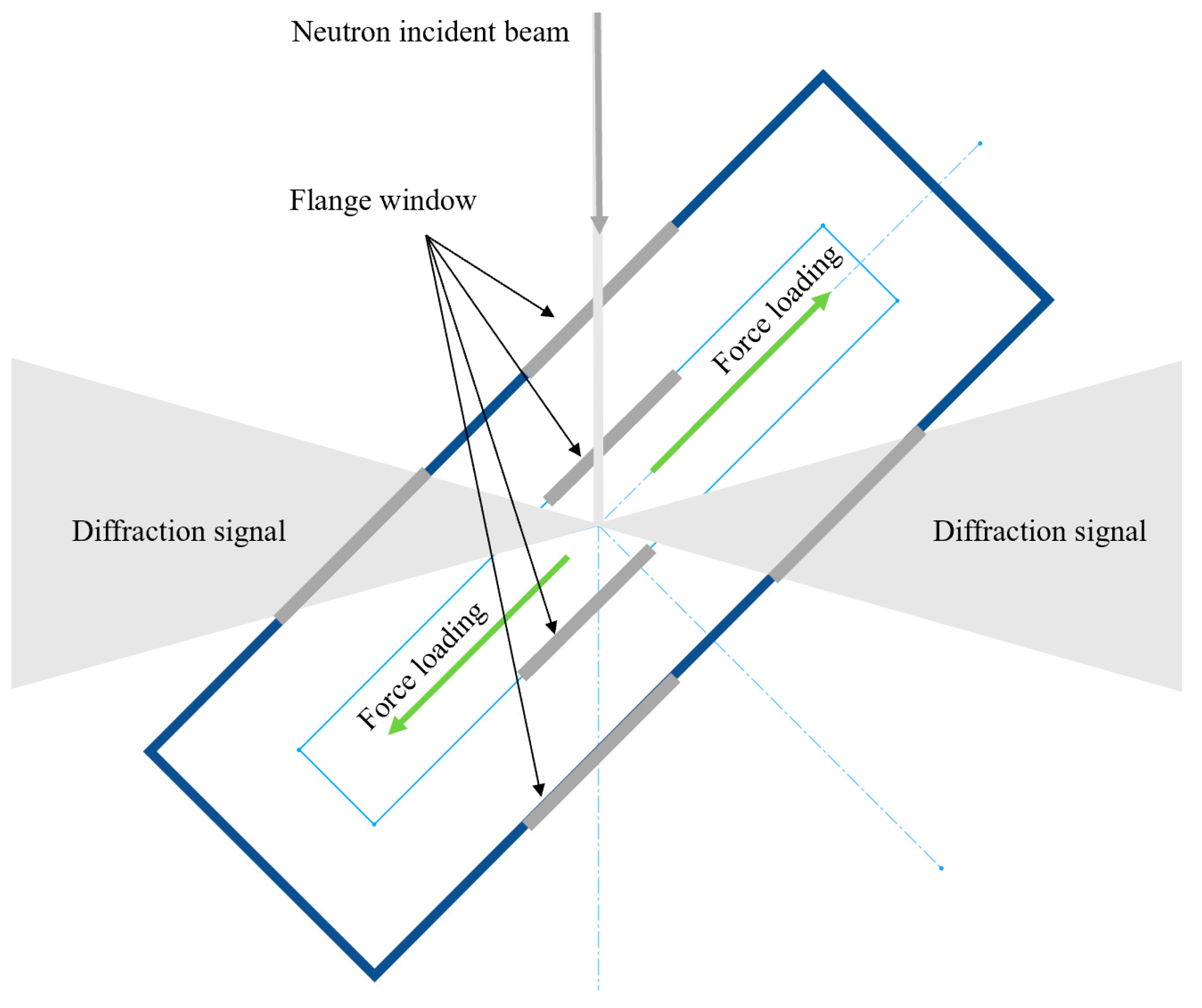
During the neutron measurement of sample strain in this experiment, the stainless-steel sample was subjected to displacement control mode. During the force loading process, the loading axis moved at a constant speed of 1 mm/min. By setting the displacement of the sample to control the strain of the sample, each deformation of the sample will be maintained for 25 min (with constant displacement each time). During this period, neutron diffraction data will be collected. After applying several displacements of the sample, the neutron diffraction patterns at the corresponding stress level were obtained.
The in situ loading experimental setup of neutron diffraction is shown in Figure 10a. The neutron diffraction measurements were conducted at the selected strain points. The neutron diffraction patterns of axial and transverse directions collected at different strains under 11 K were demonstrated in Figure 10c and Figure 10d, respectively. As the applied stress increased, the alpha phase increased, while the gamma phase decreased until it disappeared. The transition from the gamma to the alpha phase was observed as the strain gradually changed. Figure 10b shows the stress–strain curves of S30403 stainless steel obtained from tensile loading experiments.
Figure 10.
(a) The in situ loading experimental setup of neutron diffraction, (b) the stress–strain curve of S30403 stainless steel at 11 K, (c) the neutron diffraction patterns of transverse directions at 11 K under different stresses, (d) the neutron diffraction patterns of axial directions at 11 K under different stresses.
4. Conclusions
The CLFINDT designed in this study is suitable for the ERNI, and it is the first extreme low-temperature coupled stress loading device. Supported neutron diffraction low-temperature coupled stress loading experiments for many users of ERNI. The main findings of this study are as follows:
- (1)
- The CLFINDT is designed to support tensile and compressive loads up to 50 kN and low-temperature testing up to 6 K. This meets the experimental requirements for extreme low-temperature coupled stress loading of the instrument.
- (2)
- Based on previous offline low-temperature tensile data (room temperature, 77 K, and 11 K), it can be observed that the resistance performance of stainless-steel samples increases at low temperatures. The lower the temperature, the more pronounced the serrated flow becomes, as seen in the tensile curve. When the temperature of the stainless steel sample is 10 K, this phenomenon occurs due to unstable plastic deformation and repeated resistance impact. We further verified this classic phenomenon using neutron experimental data. The diffraction data clearly show the process of structural phase transition of stainless-steel materials during in situ tensile testing at room temperature and very low temperature. Through neutron in situ tensile tests, the relationship between applied stress and lattice strain can be understood. The transition of gamma to alpha phase was observed as the strain gradually changed. These results confirm the reliability and applicability of CLFINDT for studying the mechanical behavior of low-temperature materials.
- (3)
- This study developed a design method for an extreme environmental stress loading device, forming a closed loop of design, offline debugging, and data testing, and verified the performance of the equipment through in situ neutron diffraction experiments.
Author Contributions
Conceptualization, J.C.; methodology, H.Z. and J.C.; formal analysis, C.Y. and L.K.; investigation, S.W., L.Y., J.Y., and T.C.; data curation, H.Z. and Z.T.; writing—original draft, H.Z.; writing—review and editing, H.Z. and Z.T.; supervision, L.K. and J.C. All authors have read and agreed to the published version of the manuscript.
Funding
This work was supported by the National Key Research and Development Program of China under Grant No. 2025YFF0520801, the Space Application System of China Manned Space Program with No. CMSS-2024-4-A-002, the CAS Project for Young Scientists in Basic Research under Grant No. YSBR-024, the Guangdong S&T Program Nos. 2023A1111120019 and No. 2022A1515110739, and the Open Fund of the China Spallation Neutron Source Songshan Lake Science City with No. KFKT2023A05.
Data Availability Statement
The original contributions presented in this study are included in the article. Further inquiries can be directed to the corresponding authors.
Acknowledgments
We thank the staff members of the Energy-resolved Neutron Imaging Instrument (https://csns.cn/31113.02.CSNS.ERNI) accessed on 16 July 2024 at the CSNS (https://csns.cn/31113.02.CSNS, accessed on 16 July 2024) for providing technical support and assistance.
Conflicts of Interest
The authors declare no conflicts of interest.
References
- Lin, Q.; Liu, J.; An, X.; Wang, H.; Zhang, Y.; Liao, X. Cryogenic-deformation-induced phase transformation in an FeCoCrNi high-entropy alloy. Mater. Res. Lett. 2018, 6, 236–243. [Google Scholar] [CrossRef] [Scilit]
- Tang, L.; Yan, K.; Cai, B.; Wang, Y.; Liu, B.; Kabra, S.; Attallah, M.M.; Liu, Y. Deformation mechanisms of FeCoCrNiMo0.2 high entropy alloy at 77 and 15 K. Scr. Mater. 2020, 178, 166–170. [Google Scholar] [CrossRef] [Scilit]
- Bae, J.W.; Kim, J.G.; Park, J.M.; Woo, W.; Harjo, S.; Kim, H.S. In situ neutron diffraction study of phase stress evolution in a ferrous medium-entropy alloy under low-temperature tensile loading. Scr. Mater. 2019, 165, 60–63. [Google Scholar] [CrossRef] [Scilit]
- Hany, S.; Milochova, M.; Littrell, K.; Lorange, R.; Vogt, J.B.; Abi-Aad, E.; Bychkov, E. Advanced characterization of cryogenic 9Ni steel using synchrotron radiation, neutron scattering and 57Fe Mössbauer spectroscopy. Mater. Des. 2018, 146, 219–227. [Google Scholar] [CrossRef] [Scilit]
- Kim, J.G.; Enikeev, N.A.; Seol, J.B.; Abramova, M.M.; Karavaeva, M.V.; Valiev, R.Z.; Park, C.G.; Kim, H.S. Superior strength and multiple strengthening mechanisms in nanocrystalline TWIP steel. Sci. Rep. 2018, 8, 11200. [Google Scholar] [CrossRef] [Scilit] [PubMed]
- De Cooman, B.C.; Estrin, Y.; Kim, S.K. Twinning-induced plasticity (TWIP) steels. Acta Mater. 2018, 142, 283–362. [Google Scholar] [CrossRef] [Scilit]
- Zhu, L.; Lu, X.; Yang, Z.; Tan, W.; Yang, Y.; Xiao, L.; Xie, D. Study on preparation of Nb3Sn films by bronze route. Phys. C Supercond. Its Appl. 2022, 601, 1354113. [Google Scholar] [CrossRef] [Scilit]
- Nishimura, A.; Hishinuma, Y. Neutron irradiation effect on critical current and critical temperature of Nb3Sn wire. IOP Conf. Ser. Mater. Sci. Eng. 2022, 1241, 012018. [Google Scholar] [CrossRef] [Scilit]
- Woodruff, T.R.; Krishnan, V.B.; Clausen, B.; Sisneros, T.; Livescu, V.; Brown, D.W.; Bourke, M.A.M.; Vaidyanathan, R. Design, implementation, and testing of a cryogenic loading capability on an engineering neutron diffractometer. Rev. Sci. Instrum. 2010, 81, 063903. [Google Scholar] [CrossRef] [Scilit] [PubMed]
- Arai, M. Chapter 3—Experimental techniques. In Neutron Scattering; Fernandez-Alonso, F., Price, D.L., Eds.; Academic Press: San Diego, CA, USA, 2013; Volume 44, pp. 245–320. [Google Scholar] [CrossRef] [Scilit]
- Lee, T.; Park, J.; Lee, J.; Jo, I.; Cho, S.; Lee, S.B.; Lee, S.K.; Muslih, M.R.; Ryu, H.J. Residual stress measurement of SiC Tile/Al-SiCp hybrid composites using neutron diffraction. Funct. Compos. Struct. 2019, 1, 035002. [Google Scholar] [CrossRef] [Scilit]
- Langel, W. Introduction to neutron scattering. ChemTexts 2023, 9, 12. [Google Scholar] [CrossRef] [Scilit]
- Santisteban, J.R.; Daymond, M.R.; James, J.A.; Edwards, L. ENGIN-X: A third-generation neutron strain scanner. J. Appl. Cryst. 2006, 39, 812–825. [Google Scholar] [CrossRef] [Scilit]
- Bourke, M.A.M.; Dunand, D.C.; Ustundag, E. SMARTS—A spectrometer for strain measurement in engineering materials. Appl. Phys. A. 2002, 74, S1707–S1709. [Google Scholar] [CrossRef] [Scilit]
- Yang, J.; Li, J.; Liu, W.; Li, Y.; Huang, Y.; Zhou, J.; Zhang, X. Development of a load frame for neutron diffraction and fluorescent thermometry at cryogenic temperature. Rev. Sci. Instrum. 2022, 93, 073904. [Google Scholar] [CrossRef] [Scilit] [PubMed]
- Lan, Z.; Arikawa, Y.; Mirfayzi, S.R.; Morace, A.; Hayakawa, T.; Sato, H.; Kamiyama, T.; Wei, T.; Tatsumi, Y.; Koizumi, M.; et al. Single-shot laser-driven neutron resonance spectroscopy for temperature profiling. Nat. Commun. 2024, 15, 5365. [Google Scholar] [CrossRef] [Scilit] [PubMed]
- Chen, J.; Yu, C.; Zeng, Z.; Zheng, H.; Wang, S.; Tan, Z.; Yang, L.; Wang, L.; Zhang, X. The energy-resolved neutron imaging instrument at the China Spallation Neutron Source. Nucl. Instrum. Methods Phys. Res. A 2024, 1064, 169460. [Google Scholar] [CrossRef] [Scilit]
- Lienhard, J.H.V.; Lienhard, J.H., IV. A Heat Transfer Textbook, 6th ed.; Version 6.00; Phlogiston Press: Cambridge, MA, USA, 2024; Available online: https://ahtt.mit.edu (accessed on 23 November 2024).
- Bergman, T.L.; Lavine, A.S.; Incropera, F.P.; DeWitt, D.P. Fundamentals of Heat and Mass Transfer, 8th ed.; John Wiley & Sons: Hoboken, NJ, USA, 2017. [Google Scholar]
- GB/T 228.1-2021; Metallic Materials—Tensile Testing—Part 1: Method of Test at Room Temperature. Standards Press of China: Beijing, China, 2021.
- GB/T 6397-1986; Specimens for Tensile Testing of Metals. Standards Press of China: Beijing, China, 1986.
- GB/T 1220-2007; Stainless Steel Bars. Standards Press of China: Beijing, China, 2007.
- GB/T 228.4-2019; Metallic Materials—Tensile Testing—Part 4: Method of Test in Liquid Helium. Standards Press of China: Beijing, China, 2019.
- Kim, J.H.; Park, W.S.; Chun, M.S.; Kim, J.J.; Bae, J.H.; Kim, M.H.; Lee, J.M. Effect of pre-straining on low-temperature mechanical behavior of AISI 304L. Mater. Sci. Eng. A 2012, 543, 50–57. [Google Scholar] [CrossRef] [Scilit]
- Valiente Bermejo, M.A. Henry Granjon Prize Competition 2012 Winner Category B: "Materials Behaviour and Weldability" Influence of the [Creq +Nieq] alloy level on the transition between solidification modes in austenitic stainless steel weld metal. Weld. World 2012, 56, 2–14. [Google Scholar] [CrossRef] [Scilit]
- Zhang, Z.; Feng, Y.; Tan, Q.; Zou, J.; Li, J.; Zhou, X.; Sun, G.; Wang, Y. Residual stress distribution in Ni-based superalloy turbine discs during fabrication evaluated by neutron/X-ray diffraction measurement and thermomechanical simulation. Mater. Des. 2019, 166, 107603. [Google Scholar] [CrossRef] [Scilit]
- Hao, J.; Tan, Z.; Lu, H.; Deng, S.; Shen, F.; Zhao, D.; Zheng, H.; Ma, Q.; Chen, J.; He, L. Residual stress measurement system of the general purpose powder diffractometer at CSNS. Nucl. Instrum. Methods Phys. Res. A 2023, 1055, 168532. [Google Scholar] [CrossRef] [Scilit]
Disclaimer/Publisher’s Note: The statements, opinions and data contained in all publications are solely those of the individual author(s) and contributor(s) and not of MDPI and/or the editor(s). MDPI and/or the editor(s) disclaim responsibility for any injury to people or property resulting from any ideas, methods, instructions or products referred to in the content. |
© 2026 by the authors. Licensee MDPI, Basel, Switzerland. This article is an open access article distributed under the terms and conditions of the Creative Commons Attribution (CC BY) license.