


Abstract
This paper proposes a method to investigate the design properties of geotechnical seismic isolation (GSI). This technique has been the object of many research contributions, both experimental and numerical. However, methods that may be used by practitioners for design procedures are still unavailable. The formulation presented herein may be used for preliminary assessments of two important properties: the thickness and the shear wave velocity. Three-dimensional advanced numerical simulations were performed with the state-of-the-art platform OpenSees in order to verify the analytical formulation on a benchmark case study. The elongation ratio has been taken as the relevant parameter to discuss the efficiency of GSI in decoupling the soil from the structure. The main findings consist of assessing the dependency of the elongation ratio on two parameters: the thickness and the shear velocity of the GSI layer. In this regard, a novel formulation was proposed in order to make preliminary design assessments that can be used by practitioners for practical applications.
1. Introduction
Geotechnical seismic isolation (GSI) was proposed in 2008 [1] as a low-cost mitigation technique for the earthquake mitigation of structures. The main idea is that GSI can be a valid solution especially for developing countries where the construction of buildings does not provide adequate levels of structural safety during seismic events; such a technique consists of introducing a deformable interface between the soil and the structure [1,2,3,4]. In the last 15 years, such a method has been the object of several studies to improve the seismic performance of buildings. In particular, many contributions focused on investigating specialized materials to be applied in the deformable layer with the scope to reduce the seismic forces from the soil to the structures. In this regard, rubber–soil mixtures (RSMs) consist of a composite material with selected properties (such as low shear modulus of RSM), as shown in [5,6]. Other solutions were the object of experimental tests such as stone pebbles [7,8] and low-cost PVC ‘sand-wich’ (PVC-s) by [9,10], geogrid reinforcements [11], pure tire chip by [12,13] and polyurethane injections [14]. Many materials have been proposed for GSI, such as sand bitumen [15,16], geosynthetics [17,18] and sand–rubber mixtures [19,20,21].
Many applications were proposed for investigations of the beneficial effects of GSI on structural configurations [22,23,24] and bridges [25,26]. In particular, the use of tire chips as backfill materials was proposed for retaining structures and bridge abutments [27,28,29,30,31], while EPS geofoam was proposed as a protection for bridge piers [32].
Several techniques that apply GSI principles have been proposed. For example, a subsoil intervention consists of introducing flexible vertical diaphragm walls together with a soft horizontal layer [33,34]. Moreover, horizontal and V-shaped soft buried barriers were also considered as alternative techniques [35,36]. In addition, Ref. [37] proposed the so-called ‘Periodic foundation’ that consists of concrete and rubber layers to realize effective attenuation zones. In tunnels and pipeline arenas, a soft layer of coating materials was proposed [38,39].
Regarding this background, there is a gap in the literature: numerical modeling and experimental tests are extremely cost-consuming tools and may be performed only at the academic level. This means that the original proposal of a low-cost mitigation technique may be impracticable for common applications and most practitioners need to have easy-to-use design procedures to build up their models. In this regard, the main scope of this paper is to propose a manageable method for design assessments of the properties (such as the thickness and the shear wave velocity of the layer) for preliminary design procedures. The present methodology is derived from the approach proposed for the assessment of the role of soil–structure interaction (SSI) on low-rise buildings [40]; such a methodology consists of considering an equivalent fixed-based system to perform SSI analyses and was validated with non-linear dynamic numerical simulations with OpenSees. In addition, such a methodology was applied in the assessment of the detrimental effects of SSI on the traditional base isolation technique [41,42].
An existing methodology proposed by [43] consists of a lumped-parameter analytical procedure based on equivalent-linear stiffness and viscous damping coefficients along with rocking radiation damping coefficients for surface and embedded foundations. However, the principal limitation of such a methodology consists of the calibration of several coefficients that requires practice and may be particularly time-consuming.
The novelty of the present paper consists of proposing an analytical formulation that considers two main parameters: the thickness and the shear wave velocity of the GSI layer. Thickness has been chosen as the main parameter for representing the geometry of the GSI system and on which the technical cost depends. The shear wave velocity has been chosen to synthetize into a unique parameter the properties of the soil (the shear wave velocity depends on the shear modulus and Poisson ratio). The efficiency of GSI systems depends on the energy dissipation capability and thus on the thickness of the GSI layer, as discussed in [6]. In particular, the GSI layer behaves as a filter and its efficiency may be assessed as the ratio between the accelerations transmitted through to the top of the GSI layer and those measured at the base of the GSI layer. It is worth noting that the thicker the GSI layer is, the more efficient this filter effect becomes. In order to quantify the efficiency of GSI systems, comprehensive experimental and numerical investigations necessarily need to consider the thickness and the mechanical properties of the GSI layer.
In particular, it is demonstrated herein that the dynamic properties of the soil and of the structure are the key parameters for assessing the performance of the GSI layer in terms of period elongation. In addition, the relationship that is herein presented correlates the properties of the soil and of the structure (known during the design procedures) with the unknown characteristics of the GSI layer.
This paper is structured into five sections. The methodology is described in Section 2 by proposing the analytical development of the method. In Section 3, the approach was applied to a case study and numerical simulations were performed to validate the proposed formulation. In Section 4, the obtained results and findings are discussed by considering the practical applications and observations that can be used by practitioners for design purposes.
2. Methods for Design Assessments
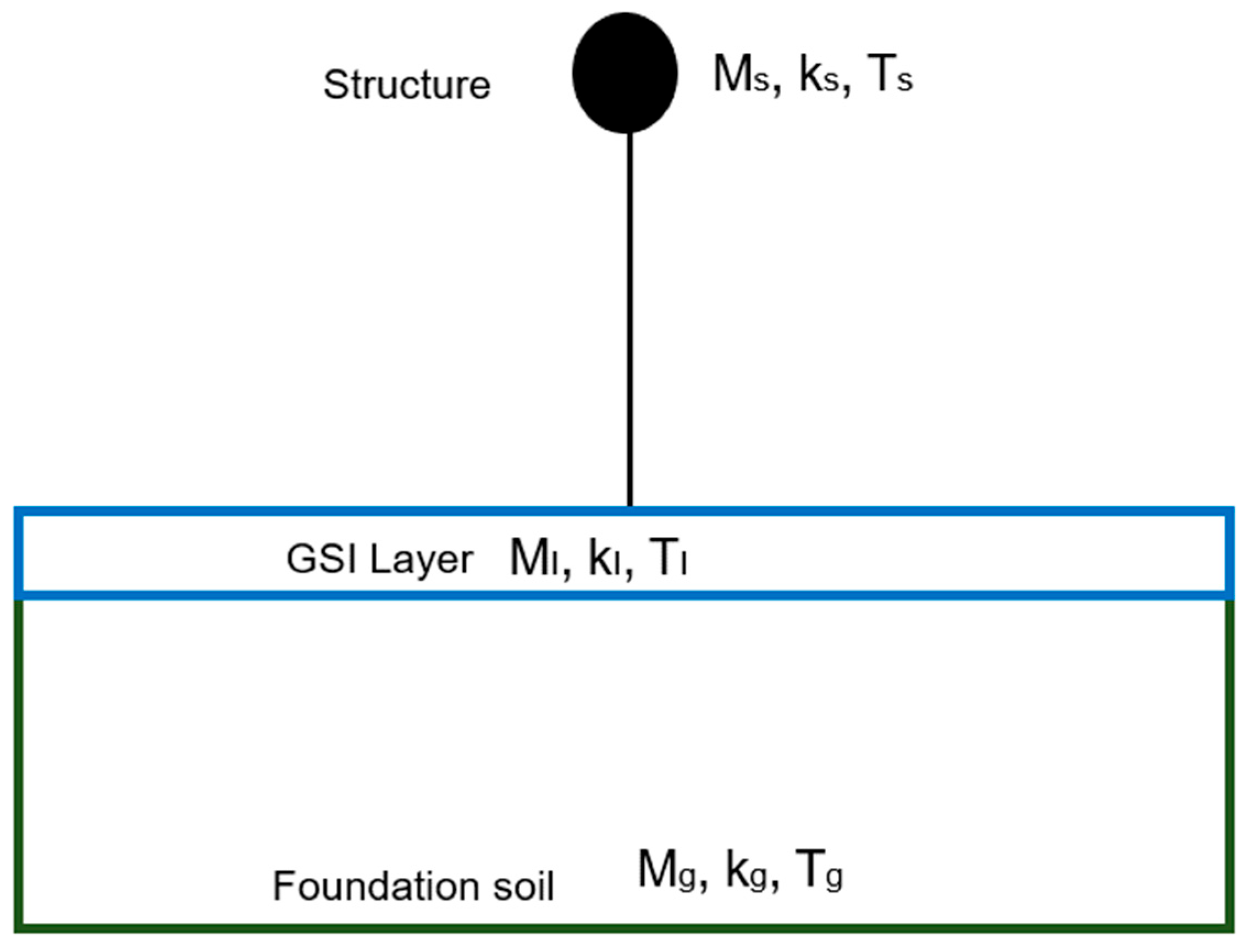
The principle of performance-based earthquake engineering design has been considered in the last few decades as the state-of-the-art approach to increase safety against earthquakes via many applications for structures [44,45] and bridges [46,47]. In this paper, this methodology is followed to assess the design properties of the GSI layer. The principal aim is to propose an analytical formulation based on the definition of a three-degrees-of-freedom (3DOF) system that is schematically represented in Figure 1:
DOF1: structure, represented by its mass (ms), its stiffness (ks) and its period (Ts);
DOF2: GSI layer, represented by its mass (mI), its stiffness (kI) and its period (TI);
DOF3: soil, represented by its mass (mg), its stiffness (kg) and its period (Tg).
It is worth noting that the 3DOF system is not an alternative to the most-advanced numerical simulations. The aim of this method is to make the design procedure of GSI faster by considering two steps.
Step 1
The 3DOF system is used for defining the thickness and the shear wave velocity, by avoiding time- and cost-consuming numerical simulations (such as parametric studies consisting of varying the two parameters) at this preliminary stage.
Step 2.
Once the two parameters have been decided, advanced numerical simulations need to be performed to assess the performance of the system (structure, GSI and soil). However, the number of these simulations will be significantly reduced because of the application of step 1.
In particular, the relationships between the structure and the foundation soil are based on the previous analytical procedure proposed in [40] built up on the definition of two main parameters that synthetize the dynamic properties of the system:
is the ratio between the structural mass (ms) and the mass of the foundation soil (mg):
is the squared ratio between the period of the structure ( and that of the soil (, or even the squared ratio between the frequency of the soil and that of the structure :
Following the approach described in [48], it is possible to consider the soil as an equivalent 1-DOF system of a and shear wave velocity :
If d and v are the thickness ratio and the shear velocity ratio, which represent the design properties of the GSI layer, they can be defined as follows:
We can derive that DOF3 and DOF2 may be condensed in an equivalent single DOF, represented by its frequency (ωeq), its shear velocity (Vseq) and its thickness (Heq):
Therefore, it is possible to calculate the period elongation of the entire system (soil + GSI layer + structure), by applying [40] the following:
where TSYS is the fundamental period of the entire system that elongates due to the presence of both the foundation soil and the GSI layer. As in [20], since the SSI effects are significant when the structural frequency is larger than that of the soil (mg >> ms), β may be considered zero. Therefore, it is possible to calculate the elongation ratio (e) by introducing (2) inside (9) as follows:
It is worth noting that the two variables d and v represent the design properties of the GSI layer, while , and are known quantities.
In the following section, a numerical case study has been performed with different models by applying OpenSees, a state-of-the-art numerical platform for non-linear advanced numerical simulations to validate the method, by verifying Equation (10).
Figure 1.
Schematic 3 DOF system.
3. Numerical Case Study
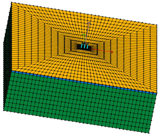
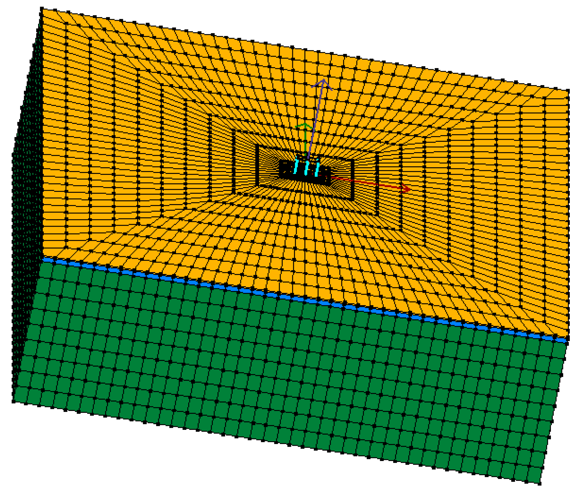
This section presents a numerical case study to validate the proposed formulation. It consists of performing several models of 3D soil–GSI–foundation–structure performed with OpenSees (Figure 2), a state-of-the-art numerical platform for non-linear advanced numerical simulations.
Figure 2.
Three-dimensional mesh. Yellow: soil S, blue: GSI layer, green: soil foundation.
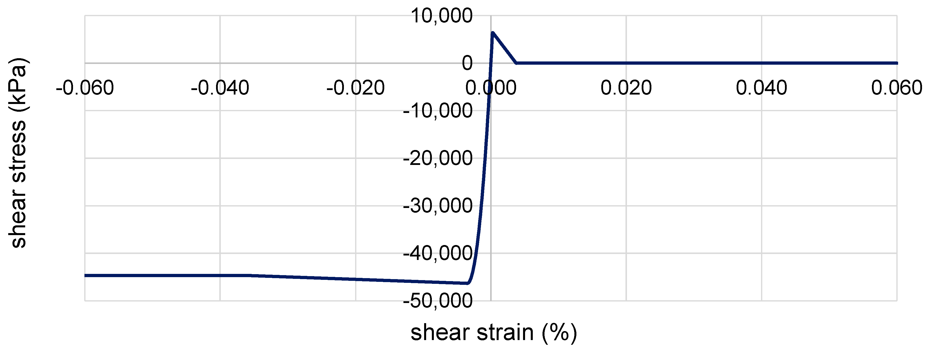
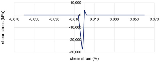
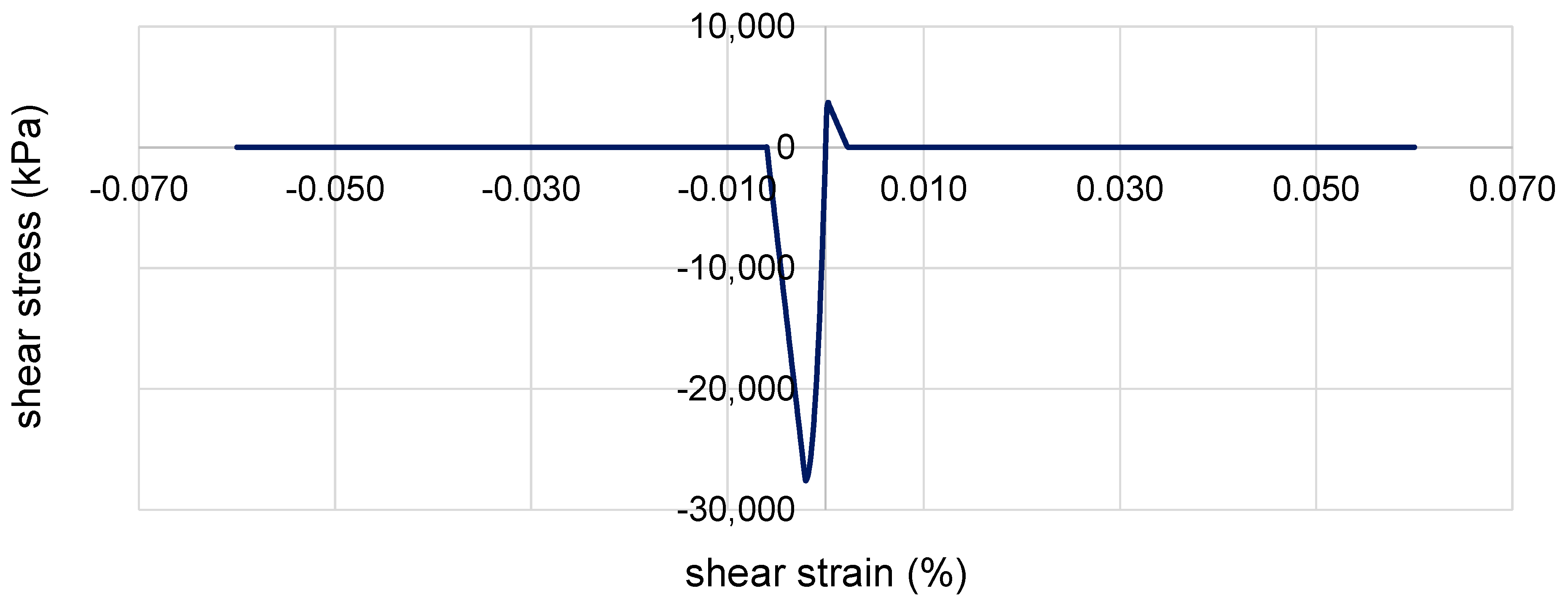
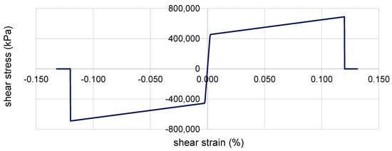
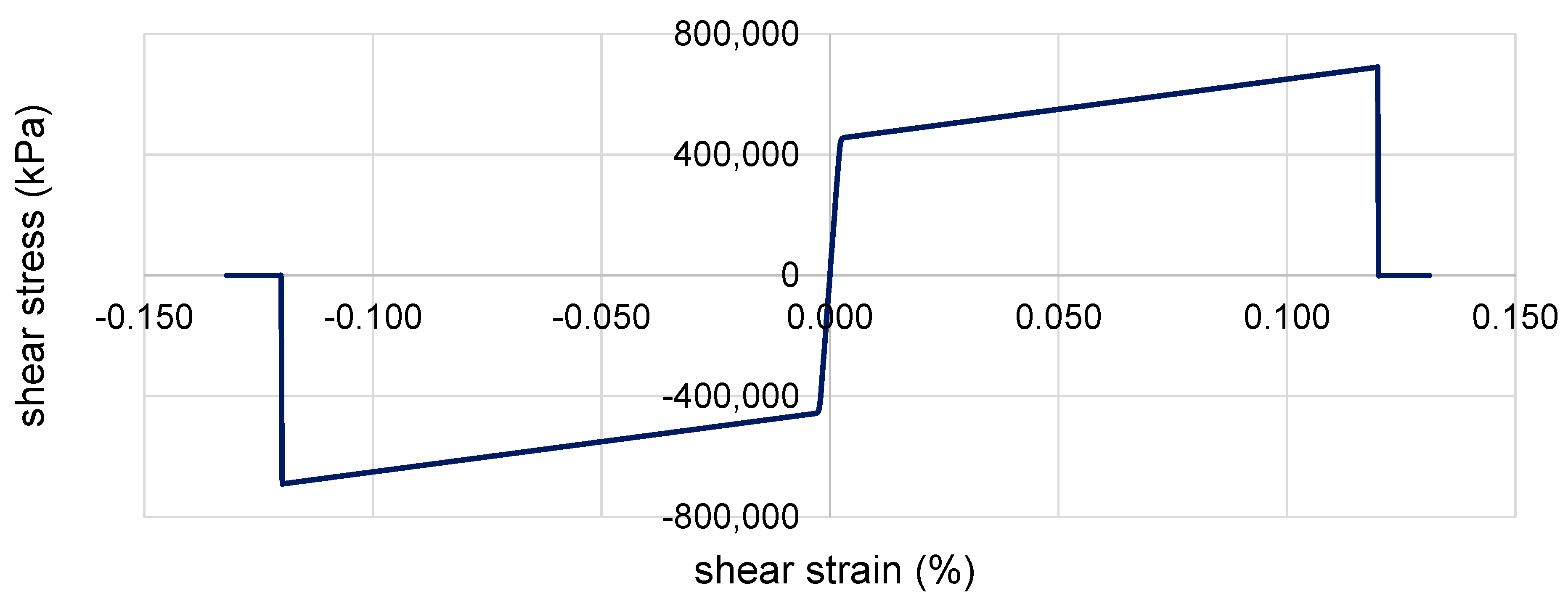
The structure represents a benchmark three-floor building (story height: 3.30 m, total height: 9.90 m, longitudinal span: 8 m, transversal span: 6 m) that aims to represent low-rise buildings for those applications GSI is targeting. The structural scheme represents typical residential buildings consisting of vertical columns (fiber section, 0.45 × 0.45 m) and horizontal rigid diaphragms for the floors. Concrete02 (see OpenSees manual [49]) was applied to model the concrete material (core and cover) and the stress–strain relationships are shown in Figure 3 and Figure 4. Steel02 (see OpenSees manual [49]) was used to represent the reinforcement bars (Figure 5). Table 1 and Table 2 show the properties adopted for the three materials. In particular, the cover concrete was assumed to lose strength by considering that zero strength is reached in the cover by a strain of 0.006, as applied in [50]. Table 3 shows the dynamic characteristics of the structure in the longitudinal direction.
Figure 3.
Shear stress–strain relationship Concrete 02 (column core).
Figure 4.
Shear stress–strain relationship Concrete 02 (column cover).
Figure 5.
Shear stress–strain relationship Steel 02 (reinforcement bars).
Table 1.
Material properties (Concrete 02).
Table 2.
Material properties (Steel 02).
Table 3.
Dynamic characteristics of the structure.
The slab foundation was represented by a 0.5 m thick block modeled with Pressure Independent Multi Yield material (density: 24 kN/m3, shear modulus: 1.25 × 10⁷ kPa, bulk modulus: 1.67 × 10⁷ kPa). In order to reproduce the interaction between the columns and the foundation slab, rigid beam–column links were used to represent the interface, as in [34]. The interaction between the soil and the foundation slab is represented by zero-length elements (see OpenSees manual [49]).
The soil mesh (200 m × 200 m × 60 m) was built up with 14,960 non-linear Bbar brick 20-node elements. The 17,220 nodes represent the three degrees of freedom (DOF) and are recorded at the corresponding integration points (see [49]). The boundaries are particularly important for SSI applications and the lateral were herein unconstrained longitudinally in order to model shear deformations, by adopting the penalty method (tolerance: 10−4), as in [41,51]. The base of the mesh was represented with an elastic surface with the aim of representing a small portion of an infinite soil domain. The mesh was calibrated to reproduce the mechanisms of the non-linear deformability of the soil by performing a convergence study between three different meshes with increasing dimensions and number of elements. Mesh dimensions were determined between 0.125 and 0.027 times of the Rayleigh wavelength. The soil domain was discretized with relatively small elements around the structure and gradually larger toward the outer mesh boundaries that were modeled to be impervious, to represent a small section of a presumably infinite soil domain and thus by allowing the seismic energy to be removed from the domain itself. In particular, lateral boundaries were modeled to move in pure shear (free-field conditions), and they were located as far as possible from the structure so as to decrease their effects on the response.
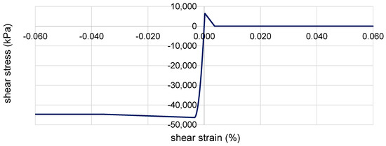
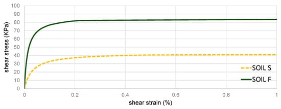
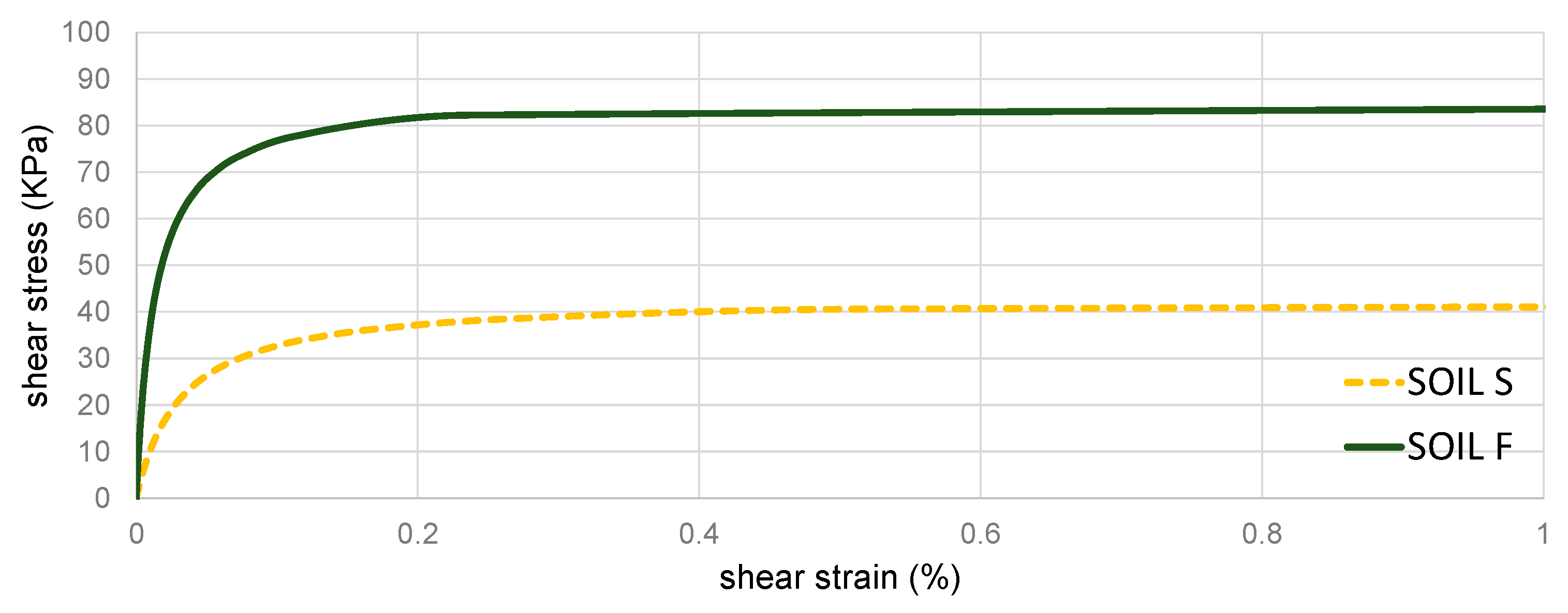
The soil materials (superficial soil (yellow in Figure 2) named soil S, GSI layer (blue in Figure 2) and foundation soil (green in Figure 2), named soil F) were modeled with the Pressure Independent Multi Yield (PIMY) to represent non-linear soil responses (such as hysteretic damping and permanent (plastic) deformations) [52]. Table 4 and Figure 6 show the properties and the backbone curve for soil S and F, respectively. Twenty models were performed with the aim of representing several case studies and verifying Equation (9). In particular, four meshes (M_1, M_2, M_3 and M_4) were built up with different thicknesses: 1 m, 2 m, 3 m and 4 m of GSI layers, respectively. For each of them, five different shear wave velocities (10, 20, 30, 40 and 50 m/s) were considered. Table 5 shows the properties for the GSI layers. Table 6 shows the cases and the results in terms of the elongation ratio (e) for the various cases studies named M_x_y, where x is the value of the thickness and y is the value of the shear wave velocity of the GSI layer. Columns 2 and 3 display the values of v and d, respectively. Column 4 and column 5 show the elongation ratio (e), calculated with (10), and the results obtained with the numerical simulations. Column 6 displays the error between the two approaches (the error varies between −1.2% and +1), demonstrating that Formulation (10) may represent the results. It is worth noting that for thinner cases, Formulation (10) overestimates the results obtained with the numerical simulations. For thicker cases, Formulation (10) is conservative. The errors may be considered due to the assumption that the 3DOF system assumes shear deformation, while the numerical model may consider the non-linear mechanisms inside the soil mesh and thus the results are more accurate. However, as mentioned above, the present approach is not an alternative to numerical simulations, and it can be adopted for preliminary assessments with the aim of avoiding many time- and cost-consuming numerical simulations.
Table 4.
Material properties (soils).
Figure 6.
Shear stress–strain relationship (soil S and soil F).
Table 5.
Material properties (GSI layers).
Table 6.
Comparison between the elongation ratio resulting from Equation (9): e (10) and the elongation ratio resulting from numerical simulations: e (NS).
4. Discussion
This section aims to describe the findings presented in Section 2 by proposing a practical discussion of the proposed methodology. In particular, from Equation (10), it is possible to derive the following:
to separate the unknown variables d and v from the known quantities.
Therefore, the design function may be considered as follows:
If its partial derivatives are calculated, it is possible to verify that increases with d and decreases with v. In other words, there is a direct proportionality with d and an inverse proportionality with v. Therefore, the optimal design would be a compromise between big thickness ratios and small shear velocity ratios. These considerations are particularly important for design purposes since the practitioners may apply (12) to preliminarily estimate the elongation ratio they want to obtain. Then, with an optimization procedure, they can calculate the design variables d and v. By this way, the proposed methodology may significantly speed up the design of GSI if compared with previous procedures or with existing academic outcomes that apply cost-consuming assessments.
In addition, the previous formulation may propose recommendations on the mutual interaction between the stiffness of the soil and the geometric set up of the GSI layer. For example, in the presence of stiff and medium soils, the stiffness of the GSI layer may be considered sufficiently thin and thus economically feasible. However, when the soil is particularly soft, it is opportune to proceed with soil compaction (i.e., air densification), in order to increase the soil stiffness and thus maintain the thickness of the GSI layer at economically feasible values.
Furthermore, the formulation proposed herein may be considered particularly important for developing both green and sustainable applications. For example, layers of rubber–soil mixtures (RSMs) are composed of scrap tires that are available in abundance with an urgent need for recycling. Therefore, the proposed preliminary assessments of GSI techniques may become particularly important for developing countries that do not have the possibility to conduct cost-consuming experimental tests to calibrate the optimal thickness and shear wave velocity. Therefore, the preliminary method may be implemented as a reference design procedure for low-cost applications.
5. Conclusions
This paper investigates the practical design of geotechnical seismic isolation (GSI) layers between the structure and the soil. The main scope is to propose a method that may be used by practitioners for preliminary design assessments. It is worth considering that the approach is not an alternative to more precise but time-consuming investigations. The application prospects are to assist designers in the definition of two variables: the thickness and the shear wave velocity of the GSI layers. The principal aim of the approach is to reduce time- and cost-consuming numerical simulations in the first preliminary stage of the design. The thickness and the shear wave velocity of the GSI layer may be preliminarily assessed in order to guarantee the GSI layer’s effectiveness in terms of filtering the seismic accelerations between the soil and the structures. Then, once these two parameters have been designed, the number of necessary advanced numerical simulations will be significantly reduced. The method has been validated with 3D advanced numerical simulations performed by OpenSees with 20 numerical cases on a benchmark system consisting of a low-rise building. The role of the two parameters was discussed to give practical remarks for practitioners in the design procedures of GSI. In addition, the findings may be the first attempt to implement the GSI technique inside code prescriptions. Future work is needed to test the method with other typologies of structures, such as mid-rise buildings and bridges. Implementing other variables could also be interesting to improve the representativeness of the proposed method.
Funding
This research received no external funding.
Data Availability Statement
Data is contained within the article.
Acknowledgments
The author wants to express his gratitude to Hing Ho Tsang for his encouragement in applying the original 3DOF model to the issue of GSI.
Conflicts of Interest
The authors declare no conflicts of interest.
Abbreviations
| ms | mass of the structure |
| ks | stiffness of the structure |
| Ts | stiffness of the structure |
| frequency of the structure | |
| mg | mass of the soil |
| kg | stiffness of the soil |
| Tg | stiffness of the soil |
| frequency of the soil | |
| mI | mass of GSI layer |
| kI | stiffness of GSI layer |
| TI | stiffness of GSI layer |
| frequency of GSI layer | |
| the ratio between the structural mass (ms) and the mass of the foundation soil (mg) | |
| the squared ratio between the period of the structure ( and that of the soil ( | |
| soil thickness | |
| shear wave velocity of the soil | |
| GSI layer thickness | |
| shear wave velocity of GSI layer | |
| Ω | the squared ratio between the frequency of GSI layer and the frequency of the soil |
| d | thickness ratio |
| v | shear velocity ratio |
| ωeq | frequency of the equivalent soil layer |
| Vseq | shear wave velocity of the equivalent soil layer |
| Heq | thickness of the equivalent soil layer |
| TSYS | fundamental period of the entire system (soil + GSI layer + structure) |
| e | elongation ratio |
| T1, T2, T3 | structural periods (first, second, third) |
References
- Tsang, H.H. Seismic isolation by rubber–soil mixtures for developing countries. Earthq. Eng. Struct. Dyn. 2008, 37, 283–303. [Google Scholar] [CrossRef] [Scilit]
- Tsang, H.H.; Lo, S.H.; Xu, X.; Neaz Sheikh, M. Seismic isolation for low-to-medium-rise buildings using granulated rubber–soil mixtures: Numerical study. Earthq. Eng. Struct. Dyn. 2012, 41, 2009–2024. [Google Scholar] [CrossRef] [Scilit]
- Tsang, H.H. Geotechnical seismic isolation. In Earthquake Engineering: New Research; Nova Science Publishers Inc.: New York, NY, USA, 2009; pp. 55–87. [Google Scholar]
- Tsang, H.H.; Pitilakis, K. Preface for the special issue on geotechnical seismic isolation (GSI). Bull. Earthq. Eng. 2023, 21, 3745–3748. [Google Scholar] [CrossRef] [Scilit]
- Pitilakis, D.; Anastasiadis, A.; Vratsikidis, A.; Kapouniaris, A.; Massimino, M.R.; Abate, G.; Corsico, S. Large-scale feld testing of geotechnical seismic isolation of structures using gravel-rubber mixtures. Earthq. Eng. Struct. Dyn. 2021, 50, 2712–2731. [Google Scholar] [CrossRef] [Scilit]
- Forcellini, D.; Chiaro, G.; Palermo, A.; Banasiak, L.; Tsang, H. Energy Dissipation Efficiency of Geotechnical Seismic Isolation with Gravel-Rubber Mixtures: Insights from FE Non-Linear Numerical Analysis. J. Earthq. Eng. 2024, 28, 2422–2439. [Google Scholar] [CrossRef] [Scilit]
- Banović, I.; Radnić, J.; Grgić, N. Effectiveness of several low-cost geotechnical seismic isolation methods: A shake-table study. Bull. Earthq. Eng. 2023, 21, 3923–3947. [Google Scholar] [CrossRef] [Scilit]
- Banović, I.; Radnić, J.; Grgić, N. Foundation size effect on the efficiency of seismic base isolation using a layer of stone pebbles. Earthq. Struct. 2020, 19, 103–111. [Google Scholar]
- Tsiavos, A.; Sextos, A.; Stavridis, A.; Dietz, M.; Dihoru, L.; Alexander, N.A. Large-scale experimental investigation of a low-cost PVC ‘sand-wich’(PVC-s) seismic isolation for developing countries. Earthq. Spectra 2020, 36, 1886–1911. [Google Scholar] [CrossRef] [Scilit]
- Tsiavos, A.; Sextos, A.; Stavridis, A.; Dietz, M.; Dihoru, L.; Di Michele, F.; Alexander, N.A. Low-cost hybrid design of masonry structures for developing countries: Shaking table tests. Soil Dyn. Earthq. Eng. 2021, 146, 106675. [Google Scholar] [CrossRef]
- Dhanya, J.S.; Boominathan, A.; Banerjee, S. Response of low-rise building with geotechnical seismic isolation system. Soil Dyn. Earthq. Eng. 2020, 136, 106187. [Google Scholar] [CrossRef] [Scilit]
- Hazarika, H.; Pasha, S.M.K.; Ishibashi, I.; Yoshimoto, N.; Kinoshita, T.; Endo, S. Tire-chip reinforced foundation as liquefaction countermeasure for residential buildings. Soils Found. 2020, 60, 315–326. [Google Scholar] [CrossRef] [Scilit]
- Kaneko, T.; Orense, R.P.; Hyodo, M.; Yoshimoto, N. Seismic response characteristics of saturated sand deposits mixed with tire chips. J. Geotech. Geoenviron. Eng. 2013, 139, 633–643. [Google Scholar] [CrossRef] [Scilit]
- Gatto, M.P.A.; Lentini, V.; Castelli, F.; Montrasio, L.; Grassi, D. The use of polyurethane injection as a geotechnical seismic isolation method in large-scale applications: A numerical study. Geosciences 2021, 11, 201. [Google Scholar] [CrossRef] [Scilit]
- Kuvat, A.; Sadoglu, E. Dynamic properties of sand-bitumen mixtures as a geotechnical seismic isolation material. Soil Dyn. Earthq. Eng. 2020, 132, 106043. [Google Scholar] [CrossRef] [Scilit]
- Kuvat, A.; Sadoglu, E.; Zardari, S. Experimental Investigation of Sand–Rubber–Bitumen Mixtures as a Geotechnical Seismic Isolation Material. Int. J. Geomech. 2024, 24, 04023293. [Google Scholar] [CrossRef] [Scilit]
- Nanda, R.P.; Dutta, S.; Das, A.; Khan, H.A. Geosynthetic liner as foundation isolation for seismic protection. Int. J. Geosynth. Ground Eng. 2017, 3, 21. [Google Scholar] [CrossRef] [Scilit]
- Yegian, M.K.; Kadakal, U. Foundation isolation for seismic protection using a smooth synthetic liner. J. Geotech. Geoenviron. Eng. 2004, 130, 1121–1130. [Google Scholar] [CrossRef] [Scilit]
- Kim, H.K.; Santamarina, J.C. Sand–rubber mixtures (large rubber chips). Can. Geotech. J. 2008, 45, 1457–1466. [Google Scholar] [CrossRef] [Scilit]
- Perez, J.L.; Kwok, C.Y.; Senetakis, K. Effect of rubber size on the behaviour of sand-rubber mixtures: A numerical investigation. Comput. Geotech. 2016, 80, 199–214. [Google Scholar] [CrossRef] [Scilit]
- Abate, G.; Fiamingo, A.; Massimino, M.R. An eco-sustainable innovative geotechnical technology for the structures seismic isolation, investigated by FEM parametric analyses. Bull. Earthq. Eng. 2023, 21, 4851–4875. [Google Scholar] [CrossRef] [Scilit]
- Chiaro, G.; Palermo, A.; Banasiak, L.; Tasalloti, A.; Granello, G.; Hernandez, E. Seismic response of low-rise buildings with eco-rubber geotechnical seismic isolation (ERGSI) foundation system: Numerical investigation. Bull. Earthq. Eng. 2023, 21, 3797–3821. [Google Scholar] [CrossRef] [Scilit]
- Dhanya, J.S.; Fouzul, M.A.; Banerjee, S.; Boominathan, A.; Zhussupbekov, A. Shaking table experiments on framed structure resting on geogrid reinforced geotechnical seismic isolation system. Bull. Earthq. Eng. 2023, 21, 3823–3849. [Google Scholar] [CrossRef] [Scilit]
- Edinçliler, A.; Yildiz, Ö. Shaking Table Tests on Geotechnical Seismic Isolation for Medium-Rise Buildings using EPS Beads-Sand Mixtures. Bull. Earthq. Eng. 2023, 21, 3851–3877. [Google Scholar] [CrossRef] [Scilit]
- Forcellini, D.; Alzabeebee, S. Seismic fragility assessment of geotechnical seismic isolation (GSI) for bridge configurations. Bull. Earthq. Eng. 2022, 21, 3969–3990. [Google Scholar] [CrossRef] [Scilit]
- Forcellini, D. Seismic resilience of bridges isolated with traditional and geotechnical seismic isolation (GSI). Bull. Earthq. Eng. 2023, 21, 3521–3535. [Google Scholar] [CrossRef] [Scilit]
- Lee, J.H.; Salgado, R.; Bernal, A.; Lovell, C.W. Shredded tires and rubber-sand as light weight backfill. J. Geotech. Geoenviron. Eng. ASCE 1999, 125, 132–141. [Google Scholar] [CrossRef] [Scilit]
- Hazarika, H.; Kohama, E.; Sugano, T. Underwater shake table tests on waterfront structures protected with tire chips cushion. J. Geotech. Geoenviron. Eng. ASCE 2008, 134, 1706–1719. [Google Scholar] [CrossRef] [Scilit]
- Xiao, M.; Bowen, J.; Graham, M.; Larralde, J. Comparison of seismic responses of geo synthetically reinforced walls with tire-derived aggregates and granular backfills. J. Mater. Civ. Eng. ASCE 2012, 24, 1368–1377. [Google Scholar] [CrossRef] [Scilit]
- Argyroudis, S.; Palaiochorinou, A.; Mitoulis, S.; Pitilakis, D. Use of rubberised backfills for improving the seismic response of integral abutment bridges. Bull. Earthq. Eng. 2016, 14, 3573–3590. [Google Scholar] [CrossRef] [Scilit]
- Mitoulis, S.A.; Palaiochorinou, A.; Georgiadis, I.; Argyroudis, S. Extending the application of integral frame abutment bridges in earthquake-prone areas by using novel isolators of recycled materials. Earthq. Eng. Struct. Dyn. 2016, 45, 2283–2301. [Google Scholar] [CrossRef] [Scilit]
- Karatzia, X.; Mylonakis, G. Geotechnical isolation of pile-supported bridge piers using EPS geofoam. In Proceedings of the 16th World Conference on Earthquake Engineering, Santiago, Chile, 9–13 January 2017. [Google Scholar]
- Kirtas, E.; Rovithis, E.; Pitilakis, K. Subsoil interventions effect on structural seismic response. Part I: Validation of numerical simulations. J. Earthq. Eng. 2009, 13, 155–169. [Google Scholar]
- Kirtas, E.; Pitilakis, K. Subsoil interventions effect on structural seismic response. Part II: Parametric investigation. J. Earthq. Eng. 2009, 13, 328–344. [Google Scholar] [CrossRef] [Scilit]
- Nappa, V.; Bilotta, E.; Flora, A.; Madabhushi, S.P.G. Centrifuge modelling of the seismic performance of soft buried barriers. Bull. Earthq. Eng. 2016, 14, 2881–2901. [Google Scholar] [CrossRef] [Scilit]
- Flora, A.; Lombardi, D.; Nappa, V.; Bilotta, E. Numerical analyses of the effectiveness of soft barriers into the soil for the mitigation of seismic risk. J. Earthq. Eng. 2018, 22, 63–93. [Google Scholar] [CrossRef] [Scilit]
- Shi, Z.; Cheng, Z.; Xiang, H. Seismic isolation foundations with effective attenuation zones. Soil Dyn. Earthq. Eng. 2014, 57, 143–151. [Google Scholar] [CrossRef] [Scilit]
- Tsang, H.H.; Lam, J.Y.K.; Yaghmaei-Sabegh, S.; Lo, S.H. Protecting underground tunnel by rubber–soil mixtures. In Proceedings of the 7th International Conference on Lifeline Earthquake Engineering, ASCE-TCLEE, Oakland, CA, USA, 28 June–1 July 2009. [Google Scholar]
- Terzi, N.U.; Erenson, C.; Selçuk, M.E. Geotechnical properties of tire-sand mixtures as backfill material for buried pipe installations. Geomech. Eng. 2015, 9, 447–464. [Google Scholar] [CrossRef] [Scilit]
- Forcellini, D. A novel framework to assess soil structure interaction (SSI) effects with equivalent fixed-based models. Appl. Sci. 2021, 11, 10472. [Google Scholar] [CrossRef] [Scilit]
- Forcellini, D. The assessment of the interaction between base isolation (BI) technique and soil structure interaction (SSI) effects with 3D numerical simulations. Structures 2023, 45, 1452–1460. [Google Scholar] [CrossRef] [Scilit]
- Forcellini, D. A 3-DOF system for preliminary assessments of the interaction between base isolation (BI) technique and soil structure interaction (SSI) effects for low-rise buildings. Structures 2024, 59, 105803. [Google Scholar] [CrossRef] [Scilit]
- Tsang, H.-H.; Pitilakis, K. Mechanism of geotechnical seismic isolation system: Analytical modeling. Soil Dyn. Earthq. Eng. 2019, 122, 171–184. [Google Scholar] [CrossRef] [Scilit]
- Alimoradi, A.; Pezeshk, S.; Foley, C.M. Evolutionary seismic design for optimal performance. In Intelligent Computational Paradigms in Earthquake Engineering; Chapter 3; Lagaros, N.D., Tsompanakis, Y., Eds.; Idea Group Publishing: Hershey, PA, USA, 2006. [Google Scholar]
- Fragiadakis, M.; Lagaros, N.D.; Papadrakakis, M. Performance-based optimum design of steel structures considering life cycle cost. Struct. Multidiscip. Optim. 2006, 32, 1–11. [Google Scholar] [CrossRef] [Scilit]
- Mackie, K.; Lu, J.; Elgamal, A. Performance-based earthquake assessment of bridge systems including ground-foundation interaction. Soil Dyn. Earthq. Eng. 2012, 42, 184–196. [Google Scholar] [CrossRef] [Scilit]
- Zelaschi, C.; De Angelis, G.; Giardi, F.; Forcellini, D.; Monteiro, R.; Papadrakakis, M. Performance based earthquake engineering approach applied to bridges in a road network. In Proceedings of the 5th COMPDYN and ECCOMAS, Crete Island, Greece, 25–27 May 2015; pp. 900–910. [Google Scholar] [CrossRef] [Scilit]
- Kramer, S.L. Geotechnical Earthquake Engineering; Prentice Hall: Upper Saddle River, NJ, USA, 1996; p. 07458. [Google Scholar]
- Mazzoni, S.; McKenna, F.; Scott, M.H.; Fenves, G.L. Open System for Earthquake Engineering Simulation, User Command-Language Manual; OpenSees Version 2.0; Pacific Earthquake Engineering Research Center, University of California: Berkeley, CA, USA, 2009; Available online: http://opensees.berkeley.edu/OpenSees/manuals/usermanual/index.html (accessed on 1 October 2024).
- Mina, D.; Forcellini, D. Soil-structure interaction assessment of the 23 November 1980 Irpinia-Basilicata earthquake. Geosciences 2020, 10, 152. [Google Scholar] [CrossRef] [Scilit]
- Forcellini, D.; Tanganelli, M.; Viti, S. Response site analyses of 3D homogeneous soil models. Emerg. Sci. J. 2018, 2, 238–250. [Google Scholar] [CrossRef] [Scilit]
- Fiamingo, A.; Abate, G.; Chiaro, G.; Massimino, M.R. HS-Small Constitutive Model for Innovative Geomaterials: Effectiveness and Limits. Int. J. Geomech. 2024, 24, 04024118. [Google Scholar] [CrossRef] [Scilit]

Disclaimer/Publisher’s Note: The statements, opinions and data contained in all publications are solely those of the individual author(s) and contributor(s) and not of MDPI and/or the editor(s). MDPI and/or the editor(s) disclaim responsibility for any injury to people or property resulting from any ideas, methods, instructions or products referred to in the content. |
© 2024 by the author. Licensee MDPI, Basel, Switzerland. This article is an open access article distributed under the terms and conditions of the Creative Commons Attribution (CC BY) license (https://creativecommons.org/licenses/by/4.0/).