


Abstract
Coupled shear wall systems are widely used in tall buildings due to their high lateral stiffness and effectiveness in controlling wind-induced serviceability responses. Reliable assessment of their behavior under realistic wind loading requires accurate load representation and properly calibrated numerical modeling. This study investigates the performance of coupled shear wall systems under wind loads derived from wind tunnel testing, where surface pressure time histories were extracted from the TPU Aerodynamic Database and used to generate equivalent full-scale, time-varying wind loads. The preliminary design of a 20-story building was established in ETABS based on current design codes. Detailed nonlinear time-history analyses were subsequently performed in OpenSees to assess the performance under three different wind hazards for the original and refined design, where shear walls were modeled using the Multiple-Vertical-Line-Element Model (MVLEM). Several wind demand indicators, including drift ratios, floor accelerations, and component and cladding performance were evaluated. The results demonstrate that the performance-based design framework enables the identification of critical vulnerabilities that may not be fully captured by conventional code-based drift and strength checks, particularly regarding localized damage accumulation and serviceability-related demands. Additionally, the refined configuration, while requiring only a 4.33% increase in total baseline concrete volume, effectively reduced peak roof drift by 60%, allowing reliable control of dynamic behavior and prevention of structural yielding, as well as ensuring the maintenance of both structural integrity and operational serviceability for the investigated high-rise configuration during severe wind events. Nevertheless, the findings are limited to the investigated building configuration and aerodynamic conditions considered in this study.
1. Introduction
Wind engineering remains one of the most challenging frontiers in structural science, driven by the increasing height and slenderness of modern buildings. A defining historical milestone was the 1978 Citicorp Center crisis, which revealed the unexpected vulnerability of unconventional structural systems to quartering winds. Although subsequent reassessments demonstrated that face winds may govern design loads in many cases [1], this event remains a benchmark in engineering awareness and design philosophy.
As buildings evolved, design strategies transitioned from simple resistance-based approaches toward integrated systems that combine redundancy, stiffness control, and energy dissipation. Taipei 101 illustrates this evolution through the use of mega-columns and a 660-ton tuned mass damper designed to mitigate both wind and seismic effects [2]. More recently, extreme wind events such as the 2024 Houston Derecho have highlighted critical vulnerabilities in façade systems, where localized amplification phenomena—particularly wind channeling between adjacent structures—can induce significant damage even when design-level wind speeds are not exceeded [3]. These observations indicate that, while global structural stability is generally ensured, localized and non-structural responses remain a major challenge in wind-resistant design.
In this context, Performance-Based Design (PBD) has emerged as a fundamental shift from prescriptive approaches toward methodologies that explicitly evaluate structural behavior under defined hazard levels. In wind engineering, this paradigm has evolved into Performance-Based Wind Design (PBWD), where structures are required to satisfy multiple performance objectives, including serviceability, operational functionality, and safety, under wind events associated with different return periods [4,5,6]. Unlike traditional design approaches based on simplified load factors, PBWD establishes a direct link between structural demand and wind hazard intensity, incorporating probabilistic methods and advanced numerical simulations to better account for uncertainties in both loading and structural response [7].
A major advancement in PBWD is the recognition that wind-induced structural response may involve nonlinear behavior. Iancovici et al. [8] demonstrated that long-duration wind excitation, when analyzed through nonlinear time-domain simulations, can induce cumulative damage and localized inelastic behavior. This finding challenges the traditional assumption of purely elastic response under wind loading and establishes wind as a potential damage-accumulating mechanism. These insights have motivated a broader reassessment of PBWD methodologies, particularly regarding the need to incorporate nonlinear structural behavior into design frameworks.
From a broader perspective, Abdelwahab et al. [9] provide a comprehensive review of PBWD, identifying it as a rapidly developing field that still lags behind seismic performance-based design in terms of maturity and standardization. Their work highlights several fundamental challenges inherent to wind loading, including long-duration excitation, strong dependence on wind directionality, and the complexity of turbulence and vortex shedding phenomena. Furthermore, they identify critical research gaps, such as the need for efficient nonlinear analysis tools, improved hazard representation, and better integration of non-structural damage and uncertainties. This study establishes a global conceptual framework for PBWD and clearly defines the barriers that currently limit its widespread implementation in engineering practice. Directly addressing these limitations, Saini et al. [10] propose an advanced PBWD framework based on Database-Assisted Design (DAD), integrating wind tunnel pressure data, nonlinear dynamic structural analysis, and site-specific climatological information. Their methodology explicitly incorporates wind directionality by generating response surfaces as functions of wind speed and direction, which are subsequently combined with probabilistic wind hazard models to evaluate performance at different mean recurrence intervals. The results of their case study show that, although the structure satisfies strength-based design criteria, it fails to meet serviceability requirements—particularly with respect to inter-story drift and cladding performance—highlighting the importance of comprehensive performance evaluation beyond traditional design checks.
Together, these contributions illustrate a critical transition in PBWD development, from the conceptual identification of challenges [9] to their implementation in advanced physics-based frameworks [10]. However, they also reveal a persistent limitation, namely the high computational cost associated with nonlinear time-history analysis and multidirectional wind simulations, which remains a major obstacle to practical adoption.
In parallel, PBWE research has progressed toward more design-oriented methodologies. Athanasiou et al. [11] introduced a multi-hazard approach integrating wind and seismic actions and proposed controlled inelasticity through wind reduction factors, while Alanani and Elshaer [12] further advanced PBWD by incorporating surrogate modeling and optimization techniques to improve computational efficiency during early design stages. More recently, Gora et al. [13] emphasized the importance of accounting for non-stationary wind hazards, demonstrating that climate change may significantly increase structural response levels and the probability of exceeding serviceability limits over the lifecycle of tall buildings.
Overall, the current state-of-the-art reflects a progressive evolution from probabilistic conceptual frameworks toward nonlinear analysis and practical design-oriented methodologies. Abdelwahab et al. [9] define the theoretical challenges and research directions, while Saini et al. [10] demonstrate one of the most advanced current implementations, integrating nonlinear behavior, wind directionality, and probabilistic hazard within a unified PBWD framework.
These developments highlight that modern wind design must simultaneously address nonlinear structural response, uncertainty quantification, computational efficiency, and evolving wind hazard conditions, paving the way toward robust, standardized, and future-adaptive performance-based wind design methodologies.
While these findings illustrate the development of performance-based wind design, its practical application to coupled wall systems remains underexplored. Nonlinear response, ductile behavior of coupling beams, and stiffness of wall piers play a critical role in energy dissipation, overstrength, and drift control. However, how these features collectively influence system performance under prolonged, cyclic wind loading remains unclear. To address these limitations, this study provides the following contributions to the field of high-rise wind engineering: (1) establishing a component-level performance framework by tracking the Deformation Damage Index (DDI) across structural panel zones under wind tunnel-derived time histories, and demonstrating that global drift metrics can mask severe local non-structural vulnerabilities; (2) characterizing the dynamic sensitivity and aerodynamic trade-offs that occur when localized structural modifications alter the building’s natural period; and (3) presenting a component-level refinement strategy aimed at improving wind-induced serviceability performance while limiting additional material consumption.
2. Methodology
A preliminary design of a 20-story building consisting of reinforced concrete coupled walls was first conducted using the software ETABS 22 following current wind and seismic design codes, where initial cross sections were assigned. Subsequently, a nonlinear time history analysis was conducted in OpenSees [14], as it enables more realistic prediction of inelastic response, plastic hinge spread, and cyclic degradation through capturing distributed plasticity and axial–flexural interaction of wall piers as well as strength degradation, stiffness deterioration, and hysteretic behavior of coupling beams. The assessment was performed for different wind hazards according to the ASCE prestandard for performance-based wind design [15] using wind tunnel time history loads extracted from the TPU aerodynamic database [16] and processed afterwards. Based on the results of the assessment, an iterative design process was conducted, resulting in a modified design which incorporates increased stiffness in the wall piers and coupling beams, as well as strengthened reinforcement in the boundary elements, and comparisons of the two designs were conducted.
Several wind demand characteristics were studied, including hysteretic behavior, roof drift, stiffness reduction, deformation damage index, and acceleration in order to enhance the current insights into inelastic behavior of tall buildings subjected to wind loads.
2.1. Building Description
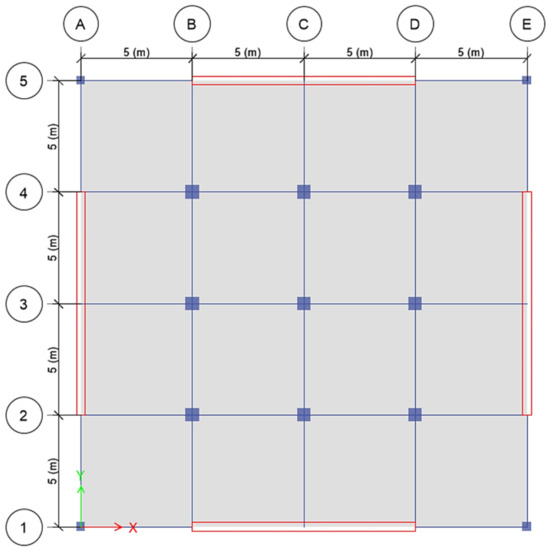
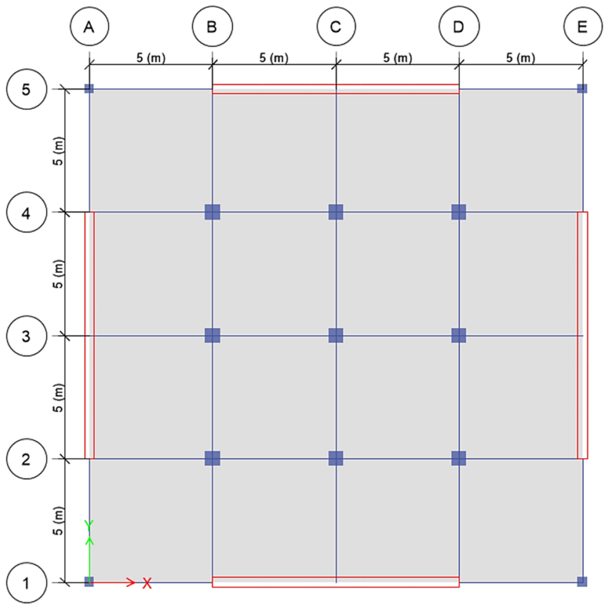
The case study is a reinforced concrete (RC) residential building with a height of H = 60 m (consisting of 20 stories with each story height = 3 m) and a square-shaped plan with a width of 20 m. The structural system consists of ordinary frames to resist gravity loads only, and two coupled walls in each direction connected by a conventionally reinforced coupling beam to resist the combinations of gravity and lateral loads, as shown in Figure 1. It is assumed that the compressive strength of the concrete is 30 MPa and its modulus of elasticity per the Syrian code is = 31 GPa [17]. The modulus of elasticity and yield strength of the steel are assumed to be 210 GPa and 400 MPa, respectively. The section properties of structural elements are reported in Table 1.
Figure 1.
Structural plan.
Table 1.
Section properties of structural elements.
2.2. Preliminary Design
A preliminary design of the building was conducted considering gravity, seismic, and wind loads. In addition to the weight of the structural members, superimposed dead load of 2 kN/m2 and live loads of 2 kN/m2 were assigned as uniform loads for floors. Dead loads of 9.23 kN/m and 5.5 kN/m were assigned to the perimeter and interior frame beams, respectively. P-Delta effects were taken into account, and the natural period and frequency of the first mode were 2.585 s and 0.386 Hz, respectively. For seismic and wind design, the loads were taken per code UBC 97 [18] and ASCE 7-16 [19], respectively, which correspond to the Syrian design code. Load combinations for strength design are reported in Table 2.
Table 2.
Syrian code design combinations.
Design parameters for equivalent static seismic and wind loads are reported in Table 3 and Table 4. As the main focus of this study is on wind loads, the site was deliberately chosen where wind loads govern the design over seismic loads.
Table 3.
UBC 97 code design seismic parameters.
Table 4.
ASCE 7-16 code design wind parameters.
2.3. Modified Design
Several enhancements were made based on the vulnerabilities detected in the original design following a judgment-driven and iterative design refinement approach. These modifications are summarized in Table 5, where the wall thickness was increased by 5 cm and the coupling beam depth was increased by 10 cm. Based on ETABS material takeoffs, the total baseline structural concrete volume is . Thickening the designated shear walls and deepening the coupling beams adds . Therefore, the total volume of the modified building becomes , confirming an overall structural material increase of just 4.33%, and verifying that the proposed structural enhancements are highly cost-effective. The reinforcement of boundary elements was also increased by 20%, while the other reinforcement ratios were kept the same.
Table 5.
Modified design properties.
Table 6 reports boundary element lengths and the longitudinal and horizontal reinforcement of wall piers and coupling beams of the original design derived from the elastic strength design in ETABS, as well as the modified boundary element reinforcement.
Table 6.
Boundary element length and reinforcement ratios.
2.4. OpenSees Modeling Approach
The model used in OpenSees was developed by Kolozvari et al. and Tauberg [20,21]. Several assumptions were made in this model, such as considering the out-of-plane stiffness of the floor slab to be small, hence resulting in insignificant axial forces on walls via wall–wall or wall–column interaction. While this formulation represents a known limitation of the 2D modeling framework, the idealization is motivated by the immense stiffness mismatch between out-of-plane slab bending and in-plane wall rigidity, alongside expected severe slab cracking under lateral demands. Also, symmetry is used such that the model is two-dimensional and consists of only two piers and one coupling beam connecting them. The analysis is performed for in-plane loads only, without considering the effect of out-of-plane deformation of the wall. Although a two-dimensional idealization was adopted to facilitate detailed tracking of local damage mechanisms, previous studies have shown that 2D coupled-wall models provide satisfactory predictions of global lateral response when torsional irregularities are limited and floor diaphragms behave approximately rigidly [20,21].
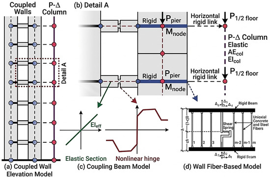
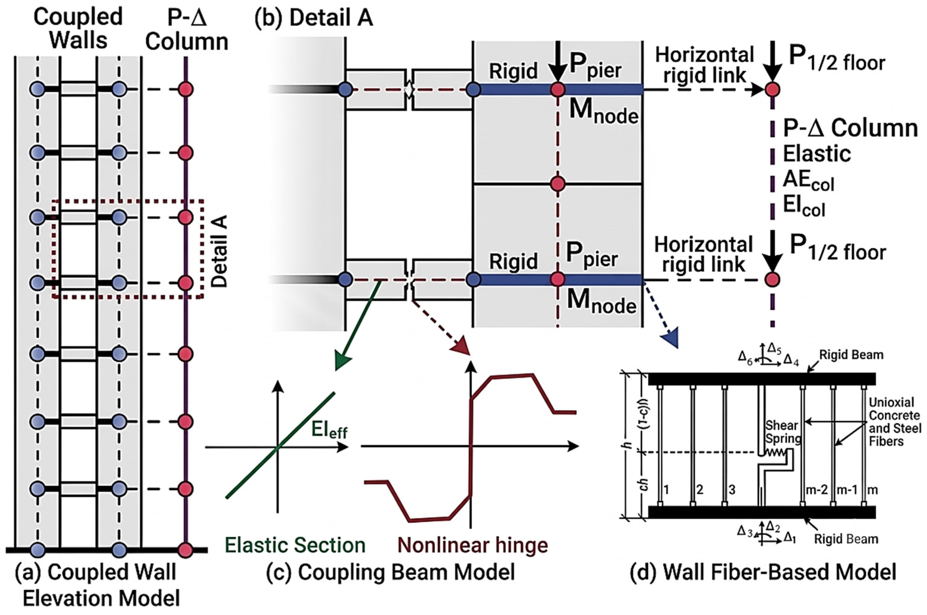
Figure 2 briefly illustrates the modeling approach. Tributary mass is assigned at the element nodes of each story, as well as the gravity loads based on corresponding tributary areas (Figure 2a). Half of the gravity loads are assigned to the P-delta column nodes of each floor, where an elastic element with a very large axial stiffness and negligible bending stiffness is assigned to the P-delta column (Figure 2b). Rigid links connect wall piers to the elastic coupling beam elements, which have a nonlinear shear hinge located at the beam midspan (Figure 2c).
Figure 2.
Modeling approach.
2.4.1. Modeling Walls
The Multiple-Vertical-Line-Element Model (MVLEM) [22] is used for modeling wall piers (Figure 2d). The fiber-based cross-sectional discretization of the MVLEM explicitly quantifies in-plane P-M coupling, directly capturing neutral axis shifts and dynamic axial force accumulation from the coupling beams. Two elements per story height for vertical discretization is deemed appropriate [20], and using a fiber size of 100 mm in the horizontal direction is also sufficient and more computationally efficient [21]. A mesh sensitivity assessment reported by Tauberg [21] demonstrated that two MVLEM elements per story provide a suitable balance between computational efficiency and numerical accuracy, with negligible variation in global response quantities compared with finer discretization. The material Concrete02 proposed by Yassin [23] is used in this study to simulate concrete behavior. Unconfined concrete behavior is based on Hognestad model [24], while the confined concrete relationship is based on the confinement model by Saatcioglu & Razvi [25]. Concrete tensile strength is estimated as (MPa) [26], and tension softening stiffness value of is used [23]. For the hysteretic behavior of reinforcing steel, the uniaxial hysteretic constitutive model SteelMPF [27] is used.
The element’s flexure and shear responses are uncoupled; therefore, the wall shear response is simulated using a linear elastic spring with a cracked effective shear stiffness of [28].
2.4.2. Modeling Coupling Beams
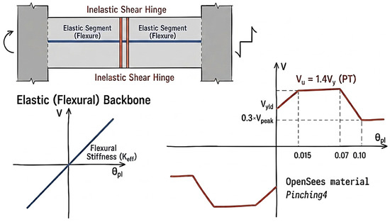
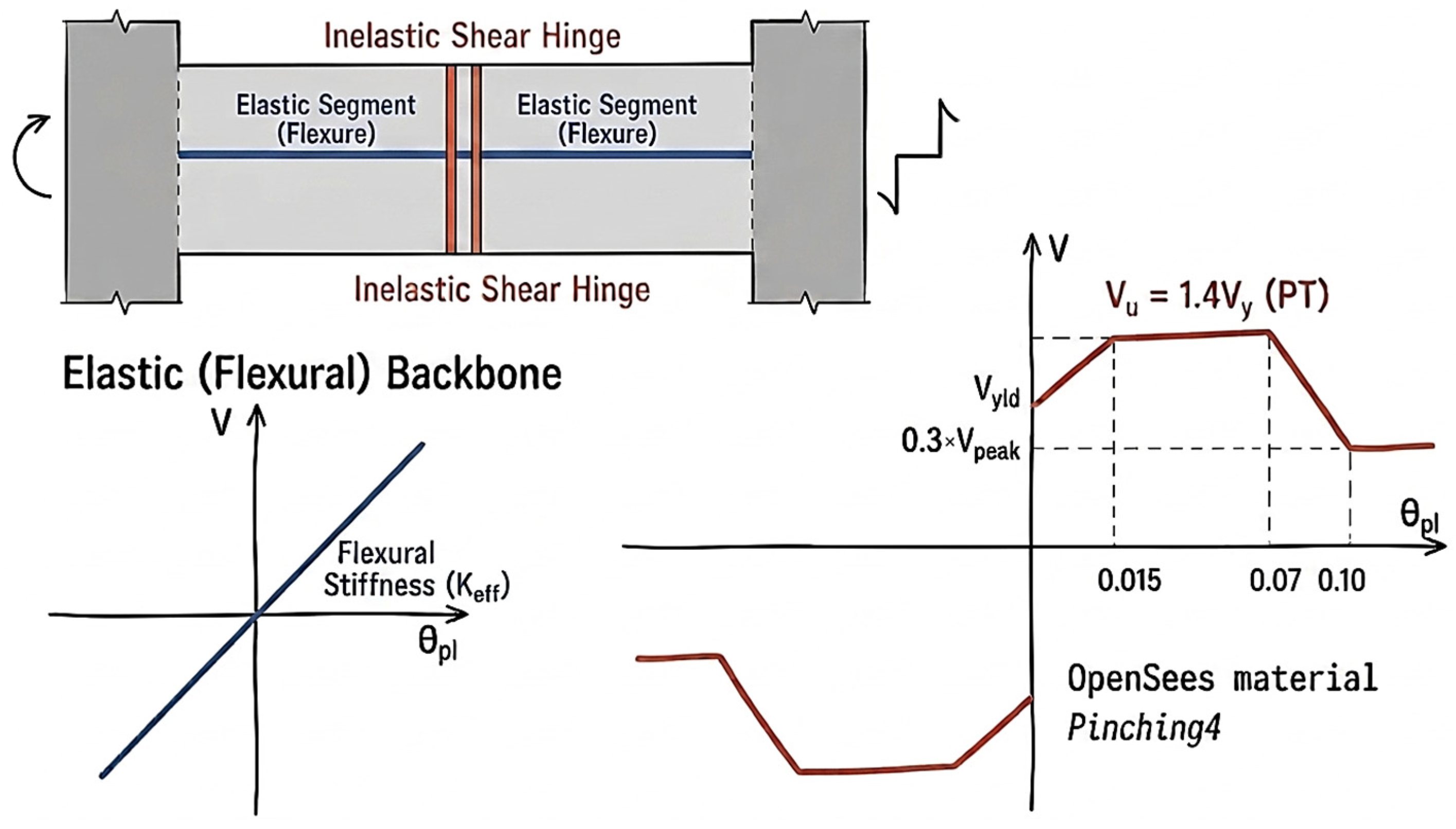
Coupling beams (Figure 3) are connected to the adjacent walls by rigid beam elements defined between the centerlines of the walls and the ends of the coupling beam element. An elastic beam element with an effective flexural stiffness of [28] is used to model deformation.
Figure 3.
Coupling beam model.
For the hysteretic shear behavior, a nonlinear shear hinge located in the center of the beam is used with material Pinching4, available in OpenSees, consisting of four main points: Point1, the yield point; Point2, ultimate shear; Point3, the point at which the shear begins to degrade; and Point4, reaching the residual force.
The coupling beam hysteretic behavior was calibrated by Tauberg [21], and Table 7 illustrates the input values of material Pinching4 for FB33 (Conventional Reinforcement).
Table 7.
Pinching4 input parameters [21].
2.4.3. Damping
A Rayleigh damping ratio of 2% was adopted, consistent with commonly reported damping levels of reinforced concrete wall structures under serviceability-level wind excitation. The first and third vibration modes were selected to compute the mass- and stiffness-proportional damping coefficients [29].
2.4.4. Validation
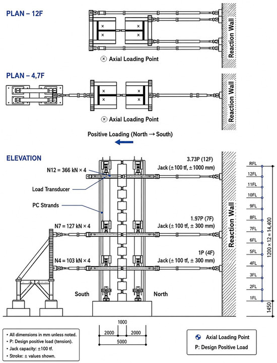
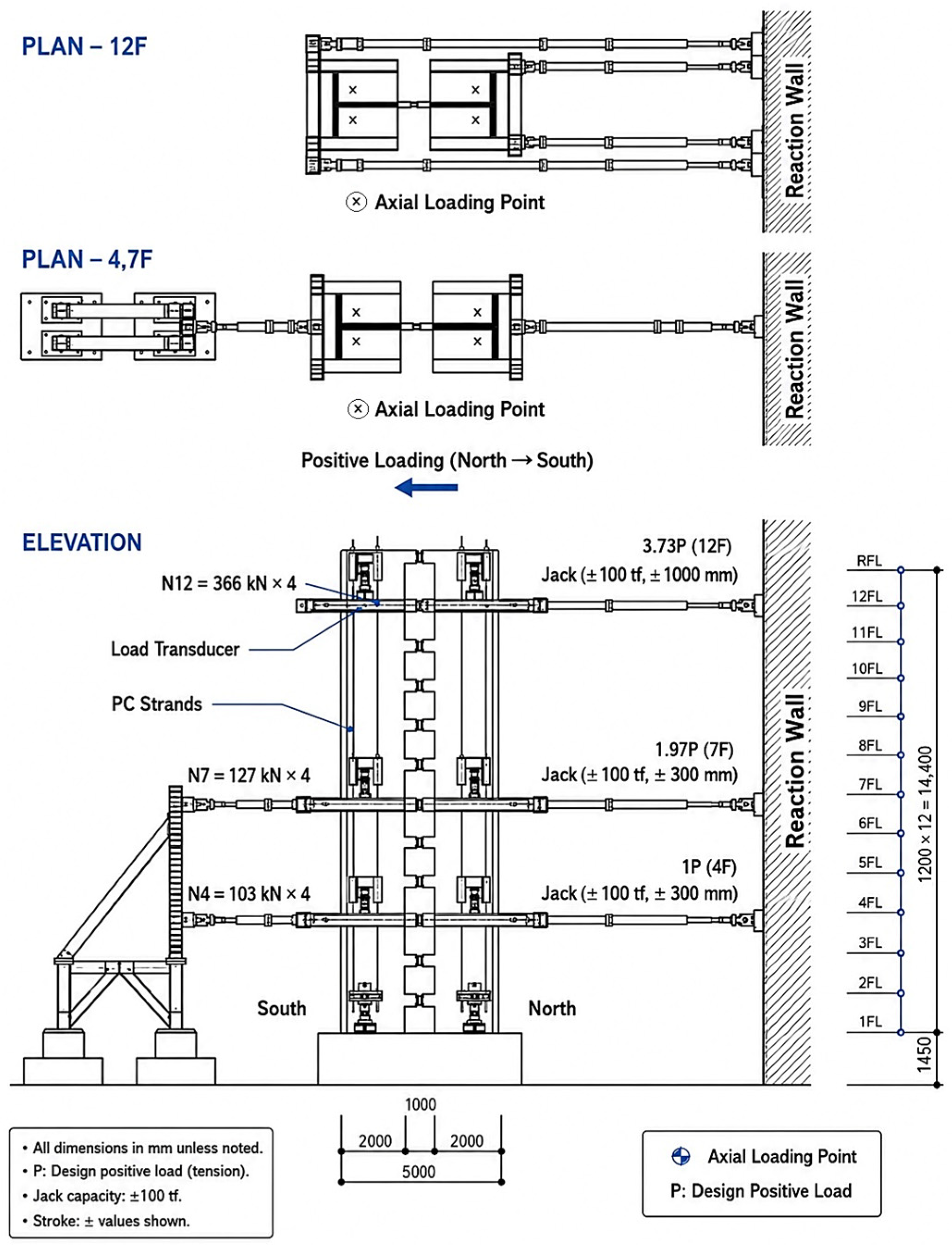
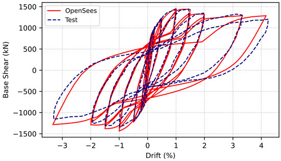
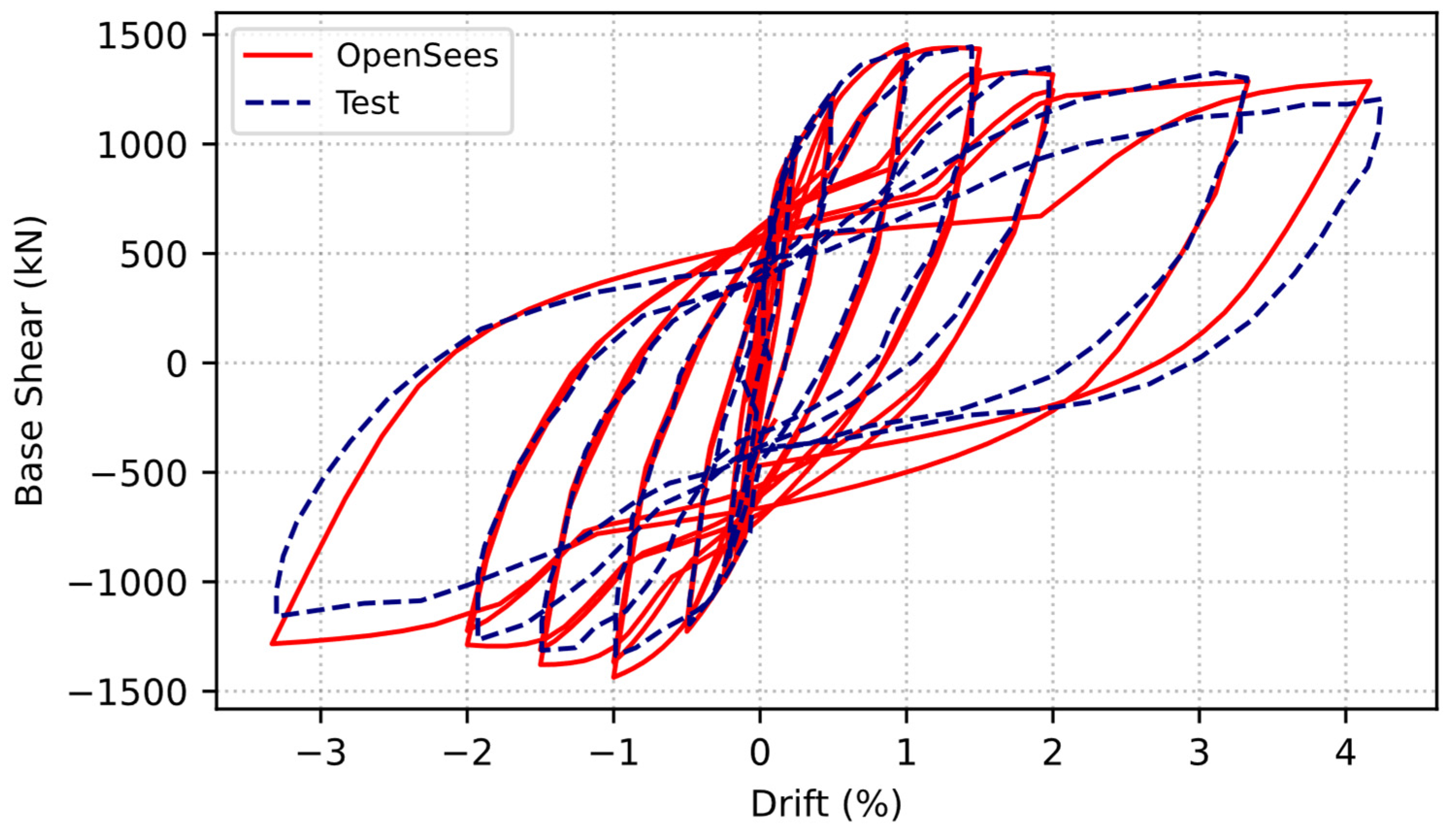
A rigorous validation of this model was conducted by the authors in a previous work using Sugaya et al.’s experimental test of a 12-story coupled wall system [30]. Figure 4 and Figure 5 illustrate the experimental setup and relationship of the base shear–12th floor drift ratio of the test vs. the analytical model. The numerical model reproduced the experimental hysteretic behavior, stiffness degradation pattern, and peak resistance with satisfactory agreement, supporting its application for subsequent wind-induced nonlinear analyses.
Figure 4.
Test setup.
Figure 5.
Experimental vs. analytical results of the 12-story coupled wall system.
While quasi-static cyclic testing differs from long-duration stochastic wind loading in frequency and load history, it serves as a validated baseline to capture material nonlinearities, stiffness degradation, and energy dissipation. Validating these fundamental structural mechanisms ensures that the numerical framework reliably predicts the hysteretic response under the alternating cyclic demands imposed by dynamic wind loading, consistent with established performance-based wind engineering methodologies [31,32].
2.5. Wind Loads for Performance Assessment
2.5.1. Wind Speeds
For a risk category II, the ASCE prestandard [15] identifies three wind hazards: 1 or 10 years MRI for the performance objective Occupant Comfort, 10 years MRI for Operational, and 700 years MRI for Continuous Occupancy (Limited Interruption). Equation (1) is used to obtain wind speed of different MRIs [33]:
The wind speed calculated above should be converted to mean hourly wind speed at the site of the building and at the building roof level using Equation (2).
where , , and are terrain exposure constants obtained from ASCE 7-16 [19], and 1.525 is the factor for conversion of 3 s averaged wind speed to hourly wind speed.
Table 8 presents basic wind speeds and the corresponding mean hourly wind speeds at the roof level for the hazard scenarios evaluated.
Table 8.
Corresponding wind speed of each hazard.
2.5.2. Wind Load Calculation and Scaling Framework
Several analytical assumptions were enforced: (1) wind-induced torque is neglected due to the building’s symmetrical plan, and a homogenous environment around the building with wind loading direction perpendicular to the face of the building along the line of symmetry is assumed [34]; (2) The correlation between the along- and cross-wind loading directions is negligible [35].
Based on this, the coupled wall system would be evaluated in two uncoupled orthogonal directions.
While this uncoupled 2D evaluation framework allows for a highly targeted tracking of localized damage, it represents an idealized boundary condition. In real-world multi-directional wind hazards, concurrent bi-axial demand states and complex wake interference from neighboring structures may induce coupled three-dimensional responses that fall outside the isolated scope of this study.
The wind loading histories are obtained from the wind pressure database for high-rise buildings (TPU) [16]. The database contains time series data of point wind pressure coefficients on the wall surfaces of different building models which were tested in wind tunnel tests. In this study, a Breadth:Depth:Height ratio of 1:1:3 was chosen for the building geometry of (20 m:20 m:60 m). This ratio was selected because it closely matches the geometric proportions of the investigated prototype structure and therefore minimizes geometric scaling discrepancies. Also, a power law exponent factor of was selected corresponding to exposure category C.
Because the TPU data represents rigid-model aerodynamic pressures governed solely by external geometry, the same pressure histories are applied to both configurations, since changing wall thickness or coupling beam depth does not alter the external geometry. The effects of altered structural stiffness and natural frequencies are natively captured through the dynamic response analysis in OpenSees.
To use the wind pressure coefficient loading histories in OpenSees, the coefficient values were converted to point load forces acting on the story levels. The pressure coefficients were used to obtain pressure values using the Bernoulli equation (Equation (3)).
where ρ is the air density and Cp is the pressure coefficient obtained from the TPU database.
The transformation of pressure histories into floor-level time-history nodes follows a two-stage processing framework. First, the instantaneous full-scale wind force at a given elevation zone, , is obtained by integrating the scaled model pressures across their respective tributary areas (Equation (4)). The pressure forces acting on opposite external faces of the building profile are summed concurrently.
where is the pressure at tap i, and is the corresponding tributary area at the full-scale structure. Because these elevation data lines do not line up with the story heights of the building, a linear interpolation function is enforced as formulated in Equation (5). The force vectors are mapped to the bounding structural floor diaphragms (j and j + 1) proportionally relative to their vertical proximity:
where and represent the absolute structural heights of the targeted floor diaphragms. Following this vertical interpolation, the total translational floor force is allocated equally to the parallel lateral-force-resisting lines due to structural symmetry. This linear allocation is standard practice in Database-Assisted Design (DAD) frameworks [10,16]. It functions as a direct static equivalence transformation that perfectly preserves the total integrated global story shears and overturning moments when mapping continuous aerodynamic pressure distributions to discrete floor levels, eliminating the risk of load amplification or the introduction of unphysical spatial eccentricities into the planar system. This process is carried out for the along-wind and cross-wind loading directions entirely independently, yielding uncoupled orthogonal loading files ready for multi-directional dynamic analysis.
The sampling time step of the TPU tests is 0.001 s, with 32,768 data points, which results in 32.77 s of total wind load duration. To go from the wind tunnel scale to the actual coupled wall system scale, the time step and total duration are multiplied by (length scale factor)/(velocity scale factor) [32]. For 10- and 700-year MRI wind loading histories, the total durations are 33.3 and 22.21 min, respectively. Lastly, a 20 s ramp is added to the beginning of the loading history in both directions, gradually increasing the forces to avoid the dynamic effect influencing the response of the building [31].
It should be noted that the wind pressure profiles utilized herein are based on an isolated, prismatic building model within the aerodynamic database. Consequently, the presented results should be interpreted as representative of isolated-building behavior. Additional studies considering neighboring buildings, interference effects, shielding phenomena, and urban canyon effects are required before generalizing the conclusions to dense urban environments.
3. Results and Discussion
The results are presented in two sections. First, the verification of the original linear design against current code drift limits and comparison of design forces; and second, the application of nonlinear time-history analyses under wind loads to assess performance.
3.1. Linear Design Verification (ETABS)
As can be seen from Table 9, base shear and overturning moments are quite similar for wind and seismic loads, which can be expected for a building of this height; however, wind loads still governs the strength design for both the wall piers and coupling beams.
Table 9.
Comparison of base shear and overturning moments of one coupled wall.
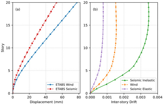
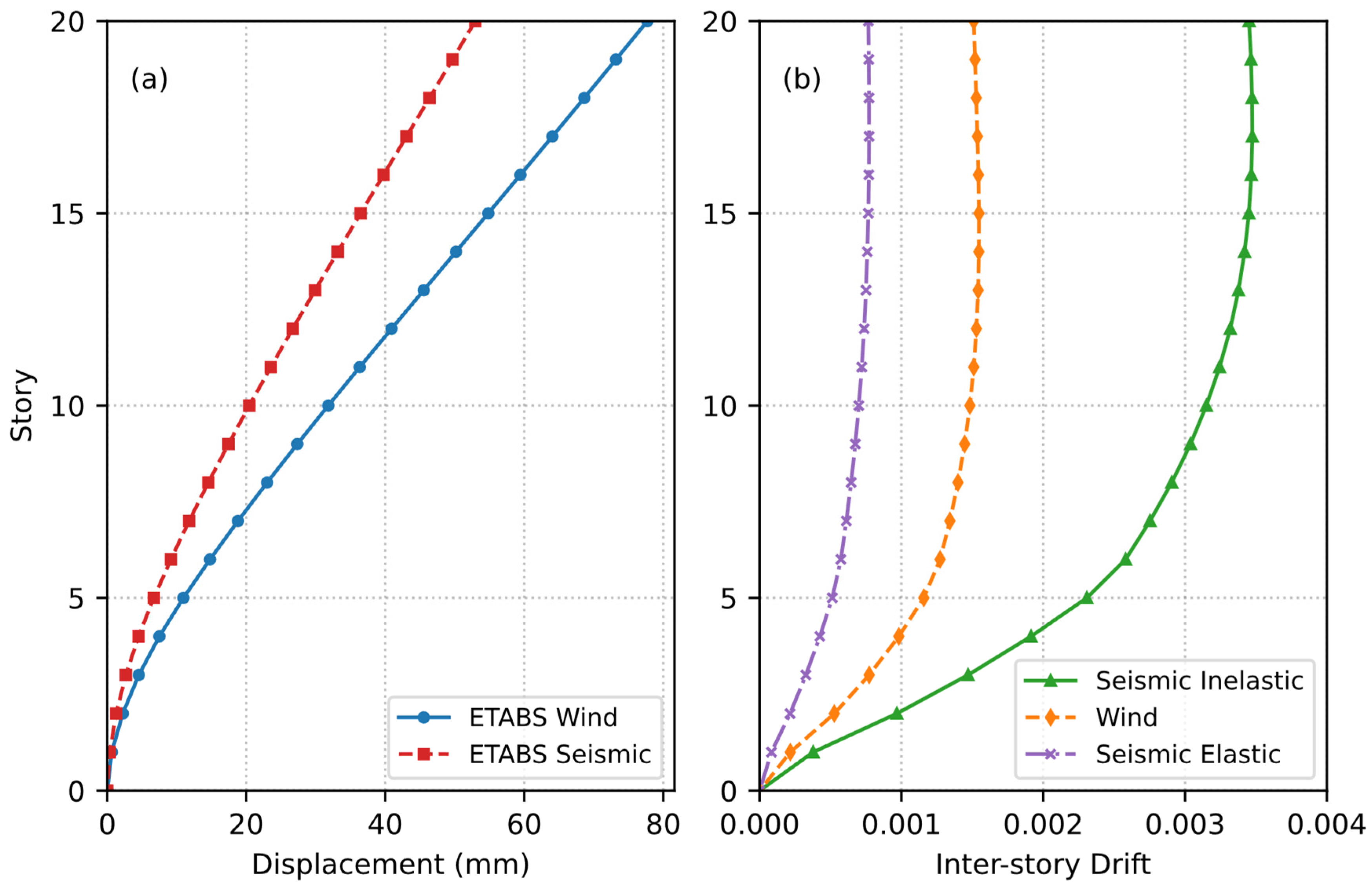
According to Figure 6, the lateral drift evaluations under wind and seismic actions demonstrate full compliance with governing building code requirements. Figure 6a illustrates that the maximum wind-induced elastic drift of 78 mm satisfies the serviceability limit of ASCE 7-16 (H/400), limiting facade and finish damage. As for the seismic load case, Figure 6b shows that the code-amplified inelastic drift ratio (0.00347) is much smaller than the allowable drift of 0.02, and the elastic serviceability drift (0.00077) is also much smaller than the acceptance criteria of /360 = 0.00278.
Figure 6.
Drift and displacement comparisons: (a) Maximum displacement; (b) Maximum inter-story drift ratio.
3.2. Performance Assessment of the Coupled Wall System (OpenSees)
3.2.1. Continuous Occupancy
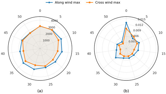
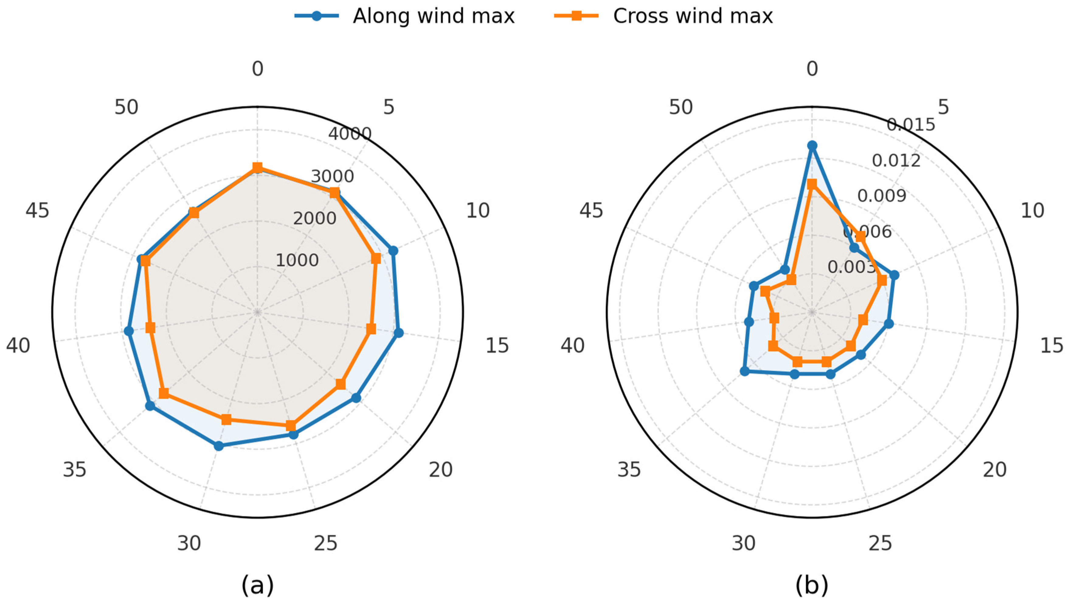
To assess the performance for Continuous Occupancy, the coupled wall original design was first subjected to nonlinear time history analysis for the 700-year MRI wind speed for 11 different directions (0°, 5°, 10°, …, 50°). Figure 7 presents max base shear and maximum roof drift for all directions for along and cross wind. As can be observed, the maximum roof drift for both along and cross winds is at the 0° direction with governing along wind. For the majority of wind angles—particularly from 10° through 45°, the along wind governs over the cross wind. However, between 50° and 5°, the cross wind converges with the along wind, signaling areas where vortex shedding or cross-wind turbulence is playing a more significant role. For the purpose of this study, only the governing direction 0° will be focused on, as it is the governing direction. Although the 0° direction governed the global response indicators investigated herein, localized demands and component-level damage may differ under oblique wind directions and therefore deserve further investigation.
Figure 7.
Maximum response for all wind loading directions of the original design: (a) Maximum base shear; (b) Maximum roof drift.
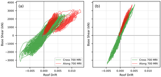
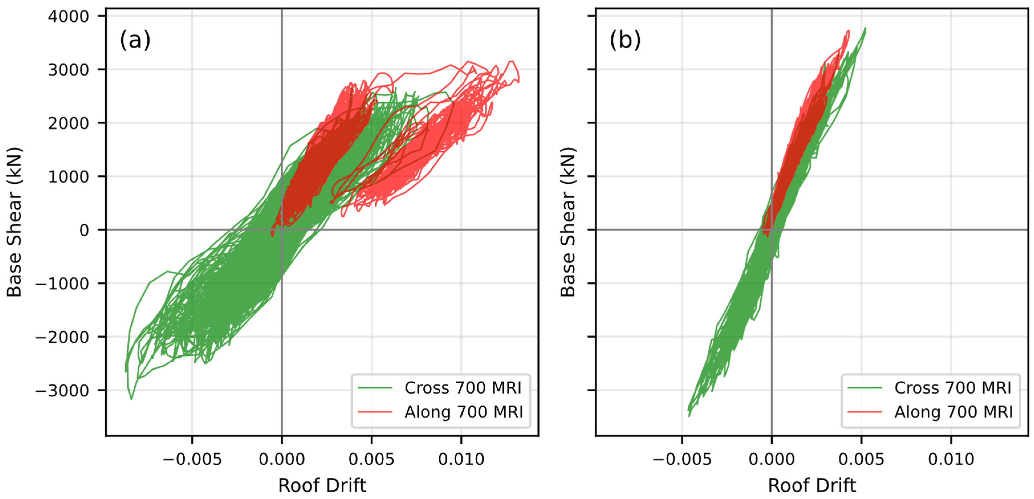
Figure 8 illustrates the global response difference between the two designs. The along wind governs the original design, which exhibits high nonlinear behavior with wide hysteretic loops, indicating significant cyclic energy dissipation. Conversely, the modified design collapses into tight, near-linear loops, storing and releasing energy elastically with minimal hysteretic damping, with a slight governing of the cross wind. In addition to that, the original design undergoes pronounced stiffness degradation and pinching behavior, which indicates cumulative concrete cracking and rebar slip as well as great damage in coupling beams. As for the modified design, the reinforcement of boundary elements succeeded in maintaining a uniform global stiffness throughout all cycles with very small degradation.
Figure 8.
Base shear vs. roof drift hysteretic response: (a) Original design; (b) Modified design.
For drift demands, the modified design drastically improves serviceability by reducing peak roof drift by over 60% for along wind (from 0.013 to 0.005), which is the acceptance criteria for roof drift ratio (H/200) according to the ASCE prestandard [15]. Furthermore, while the original design accumulates substantial permanent residual drift, the modified design consistently passes through the origin or near it, achieving the acceptance criteria of H/1000 = 0.001 × H.
Due to enhanced stiffness, the modified design attracts a higher peak base shear of about 3700 kN versus approximately 3100 kN in the original design. However, the enhanced reinforcement of boundary elements and thickened piers successfully withstand this additional demand.
Table 10 tracks the sequencing of local limit states at the base of the wall piers against roof drift. Concrete cracking occurs at a slightly lower drift in the modified design compared to the original design as an effect of increased structural stiffness, which attracts higher flexural stresses at smaller global displacements. As for reinforcement yielding, in the original design it occurs at drifts of 0.0088 (along wind) and 0.0095 (cross wind), with concrete compression reaching its peak strength at 0.0125. This confirms that the wide hysteretic loops in the original configuration are driven by extensive cracking and severe material degradation at the pier base. Crucially, neither steel yielding nor concrete crushing is reached in the modified design, successfully confining the damage to initial micro-cracking and halting damage progression.
Table 10.
Local limit states at the base of the wall piers.
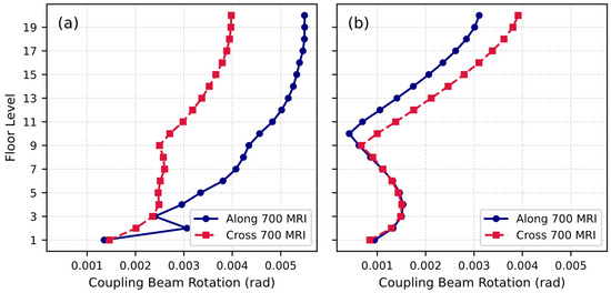
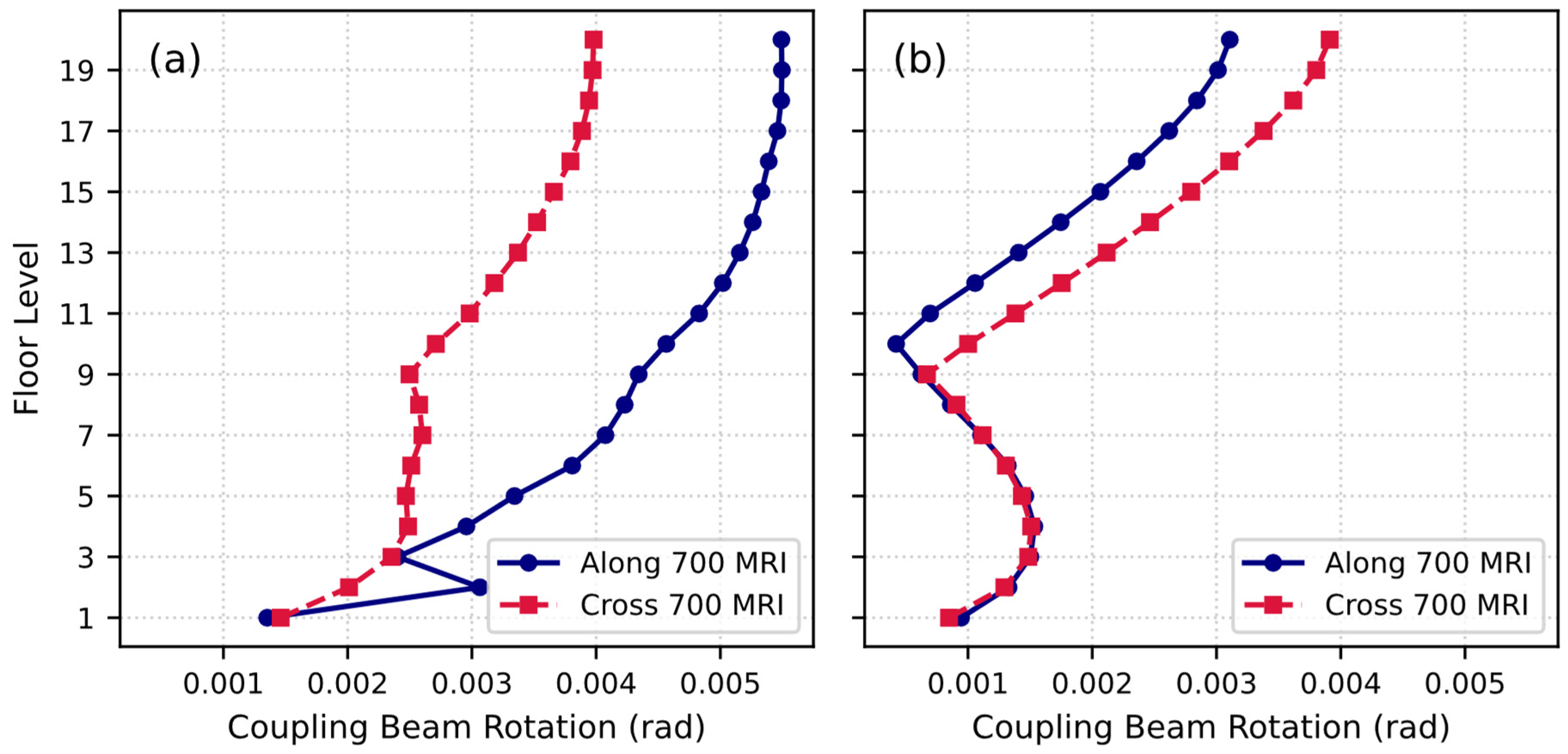
The coupling beam rotation across floors (Figure 9) reveals a significant reduction and redistribution of deformation demands due to the structural modifications. The original design experiences severe rotation demands in the upper floors, while the modified design reduces these peak demands to lower than 0.004 rad, significantly lowering plastic deformation. The localized deformation at Floor 2 is completely removed in the modified structure, and both along- and cross-wind rotations are tightly controlled below 0.0015 rad throughout the lower half of the building (Floors 1–11). While along-wind demands govern the upper floors of the original structure, the increased stiffness of the modified system shifts the governing demand to cross wind.
Figure 9.
Coupling beam rotation across floors: (a) Original design; (b) Modified design.
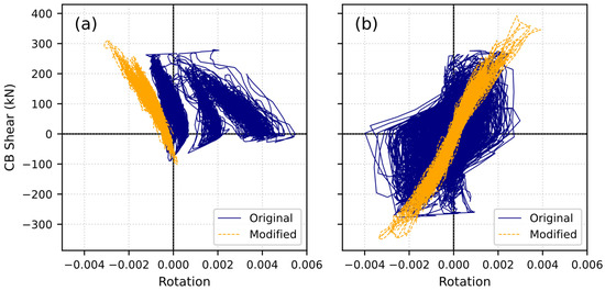
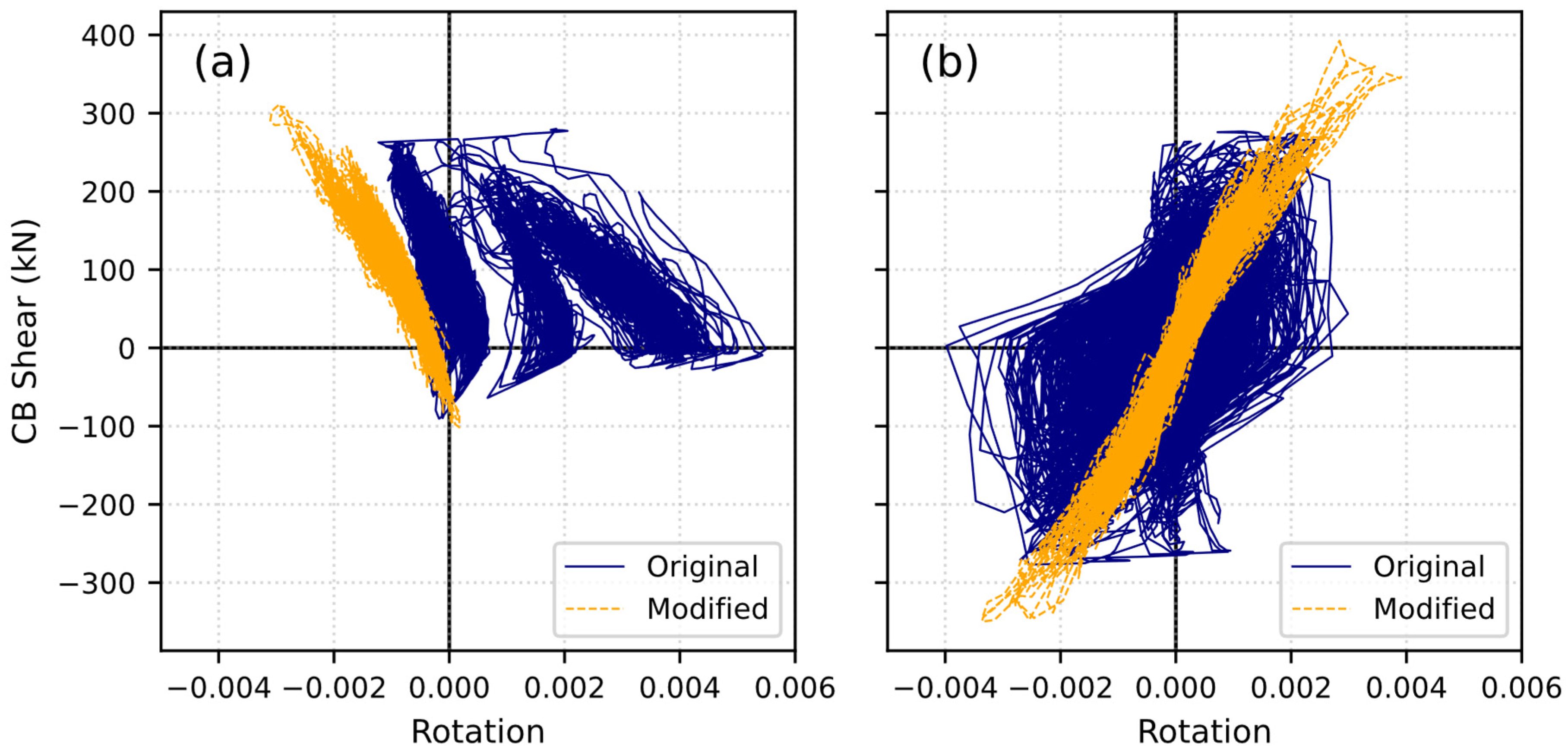
To better understand the impact of the structural modifications, the shear force versus chord rotation response for the coupling beams at the maximum chord rotations are plotted in Figure 10. The original design highlights severe inelastic vulnerability, whereas the modified curves demonstrate an enhanced, high-stiffness response. For along wind, the original design experiences evident ratcheting progressing into the positive rotation region due to the strong mean wind component, and accumulating an unrecoverable residual rotation of about 0.0035 rad, indicating localized concrete crushing. As for the modified design, limited peak rotations of about 0.003 rad is reported, and a linear, steep response profile can be observed. It can be concluded that the thickened wall piers effectively suppressed global geometric drift, forcing the modified coupling beams to remain within a stable, near-elastic recovery mechanism.
Figure 10.
Coupling beam response at the critical maximum rotation: (a) Along; (b) Cross.
Under cross wind, the original design undergoes extensive cyclic damage, severe concrete degradation, and diagonal shear cracking, as well as shear aggregate interlock, causing wide and highly pinched hysteretic loops with a flat zero-shear plateau. On the other hand, the modified design completely eliminates this pinching behavior, turning the response into tight, linear-elastic loops.
The results suggest that for this 20-story configuration, targeted strengthening of critical cyclic-demand regions such as coupling beams may represent a more material-efficient strategy than uniform global increases in wall dimensions, although additional case studies are required to confirm this observation.
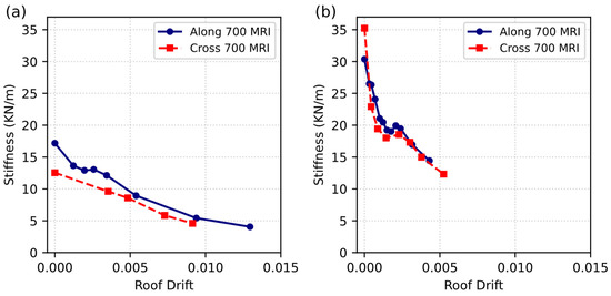
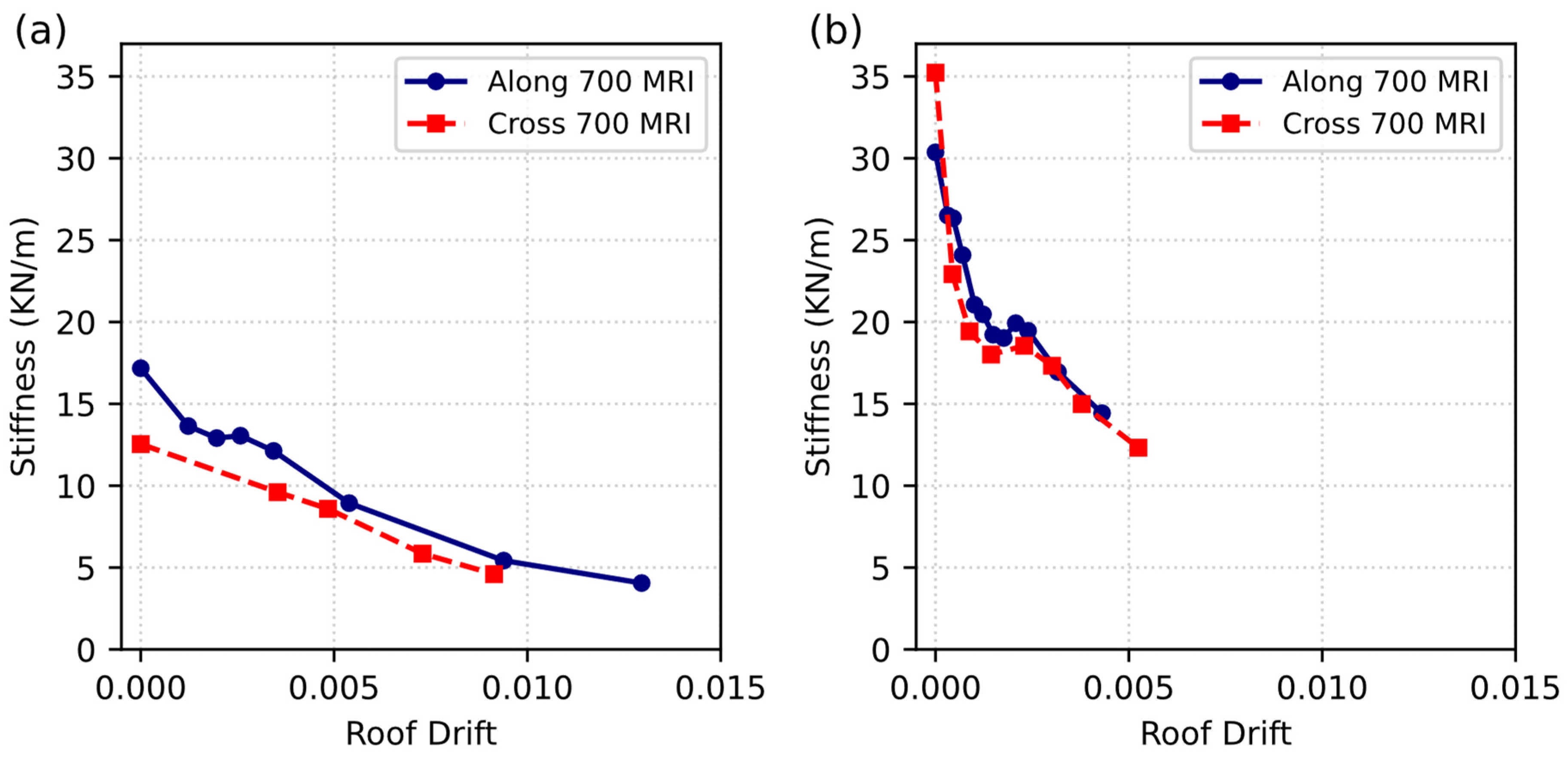
To evaluate progressive structural damage and lateral stability under the 700-year MRI wind event, the global secant stiffness was tracked against the roof drift ratio (Δ) (Figure 11).
Figure 11.
Secant stiffness degradation corresponding to roof drift: (a) Original design; (b) Modified design.
The structural modifications significantly increased the initial elastic stiffness of the system, as the initial stiffness of the original design went from 17.2 kN/mm (along-wind) and 12.5 kN/mm (cross-wind), to 30.5 kN/mm (along-wind) and 35.2 kN/mm (cross-wind) for the modified design. These represent 77.3% and 181.6% increases in initial stiffness, respectively. The reversal of the governing direction—where cross-wind stiffness exceeds along-wind stiffness in the modified structure—is due to the shortened fundamental period of the stiffer system (2.87 s for the original versus 2.47 s for the modified design, according to OpenSees analysis). This period shift alters the building’s dynamic sensitivity, mobilizing higher stiffness to resist resonant vortex-shedding frequencies.
The progression of stiffness loss reveals fundamentally distinct mechanical behaviors between the two configurations: the original design suffers systemic degradation. As can be seen from following the concrete cracking at (Δ = 0.0013), the original structure exhibits severe continuous stiffness decay. Driven by boundary element reinforcement yielding (0.0088, 0.0095) and concrete crushing (Δ = 0.0125), the stiffness drops to a residual value of 4.0 kN/mm. This unmitigated degradation indicates a severe loss of coupling action and extensive plastic damage at the base of the pier walls.
As for the modified design, the stiffness stabilizes across the wind event, exhibiting an initial stiffness reduction up to a roof drift of 0.0015, corresponding to controlled outer-fiber concrete micro-cracking (Δ = 0.0011). However, the degradation curve stabilizes into a distinct stiffness plateau between Δ = 0.0015 and 0.0035, maintaining a stiffness of approximately 20 kN/mm before settling at a final residual value (between 11 and 14 kN/mm).
Ultimately, the modified design limits total stiffness loss, by preventing reinforcement yielding and concrete crushing, where the enhanced boundary elements and deeper coupling beams successfully constrained damage propagation.
3.2.2. Operational
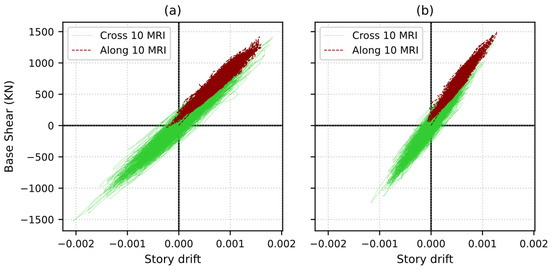
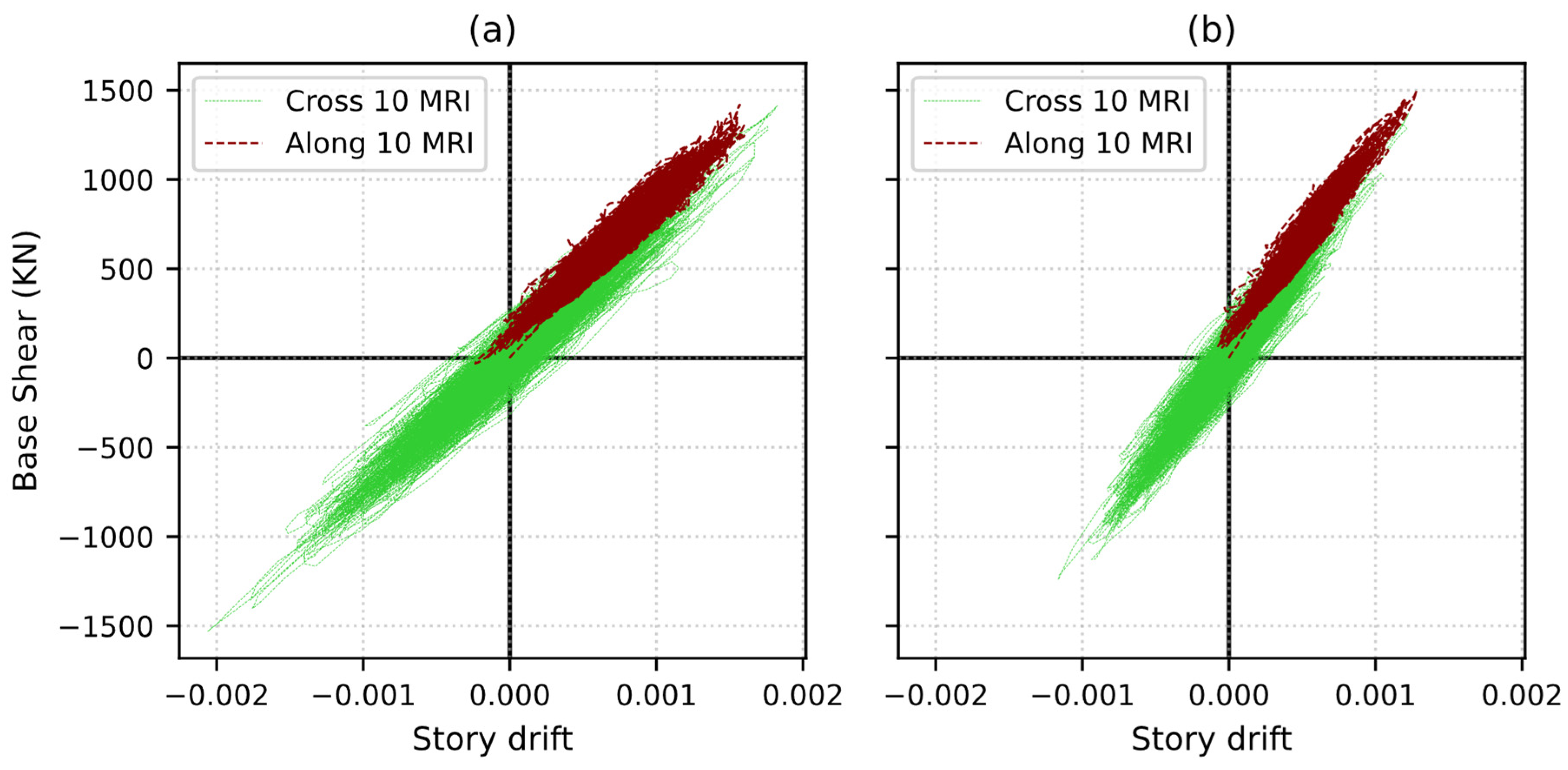
Figure 12 compares the global hysteretic responses of the original and modified coupled wall systems under a 10-year MRI wind hazard. Both configurations satisfy the operational target drift limit of H/400 = 0.0025 × H, confirming elastic performance with negligible energy dissipation. In both designs, the along-wind response remains highly constrained, reaching maximum roof drifts of 0.0015. The cross-wind demands clearly dominate the lateral response due to dynamic excitation; however, the proposed structural modifications—increased wall thickness, deeper coupling beams, and enhanced boundary element reinforcement—significantly stiffen the system. This refinement successfully increases the serviceability safety margin against non-structural damage, and limits the peak cross-wind roof drift to approximately 0.0012 (a 40% reduction).
Figure 12.
Global response for the Operational performance objective: (a) Original design; (b) Modified design.
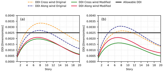
To evaluate localized structural and non-structural vulnerability accurately, the Deformation Damage Index (DDI) was calculated for the panel zones (the zone enclosed by the wall piers and coupling beams) (Figure 13a). According to the ASCE prestandard [36], in high buildings the actual “racking” deformation experienced by infill panels and cladding due to significant dominance of axial deformations and global flexural rotation in vertical elements can be misrepresented by the traditional story drift ratios. Therefore, in order to isolate the actual in-plane shear strain responsible for structural damage, the DDI is computed based on the relative displacements of four nodal points, as expressed in Equation (6).
where and represent the height and length of the panel element, respectively. By utilizing this damage index, the local performance assessment reveals a critical vulnerability in the original design. While global response showed acceptable roof drift for the original design, the local DDI captures severe localized shear strain concentrations exceeding the 0.0025 DDI limit between stories 4 and 14. Conversely, the increased stiffness and enhanced coupling efficiency of the modified system effectively suppress these localized shear strains, ensuring the entire height of the structure remains well within the allowable 0.0025 DDI limit. For practicing engineers, this confirms that relying on global building drift limits alone is insufficient; local indices like the DDI must be explicitly evaluated to safely protect non-structural facades and interior partitions from localized racking.
Figure 13.
Deformation Damage Index (DDI) across floor levels for: (a) angle 0°, (b) angle 45°.
To verify localized performance under oblique wind conditions, a supplementary evaluation was conducted under a 45° wind direction (Figure 13b). The peak DDI values obtained under the 45° angle are lower in magnitude compared to the governing 0° direction. However, they exhibit similar performance characteristics; the original design results in a peak DDI of 0.0031, which exceeds the allowable damage threshold of 0.0025. In contrast, the modified design effectively controls the localized racking deformations under frequent wind events, reducing the peak DDI to 0.0021. This demonstrates that the proposed structural refinement provides consistent protection against localized non-structural damage across both 0° and 45° wind load cases.
3.2.3. Occupant Comfort
The motion comfort during more frequent but smaller wind intensities is of great importance in the design of wind-sensitive buildings; therefore, the motion comfort performance of the coupled wall in this study (both original and modified designs) is evaluated using the approach of perception ranges (Table 11) used in practice, as provided by Chang [36] using 10-year MRI wind speed. For the original design, the peak acceleration calculated according to Johann et al. [37] was equal to 21.1 mg and 25 mg for along and cross wind, respectively, corresponding to the annoying range of the comfort scale. For the modified design, peak accelerations reached 16 mg and 20.4 mg for along and cross wind, respectively, still in the annoying range but sitting nearly at the lower boundary of the threshold, which represents a marked improvement in serviceability performance of occupant comfort.
Table 11.
Occupant comfort assessment based on peak floor acceleration criteria [36].
A similar behavioral trend was observed for motion comfort under the 10-year MRI wind hazard at a 45° angle. Although the absolute acceleration values are lower than those under the critical 0° wind vector, the original design still fails comfort thresholds in cross wind, with peak floor accelerations reaching 18.5 mg, along with an acceptable value of 12.36 mg for along wind. Implementing the modified structural layout successfully brings these demands down to 14.3 mg and 9.7 mg for along and cross wind, respectively, ensuring that acceptable occupant comfort is maintained across 0° and 45° wind orientations.
4. Conclusions
This paper presents a performance-based wind evaluation of a 20-story RC coupled wall system, both an original code-compliant design and a modified configuration with increased wall thickness, deeper coupling beams, and enhanced boundary reinforcement. The following conclusions are drawn:
- The original design satisfies the current linear code design methodologies in terms of serviceability and strength limits under wind loads.
- Based on the response assessment, the 0° direction was found to govern both along- and cross-wind loads; it was therefore chosen as the focus of this study.
- Under a 700-year MRI wind hazard, the original design exhibits severe degradation, with roof drifts up to 0.013. The modified design reduces peak roof drift by 60% (to 0.005) with only a 4.33% increase in concrete volume, meeting continuous occupancy criteria.
- The original design experiences base pier yielding and concrete crushing under along-wind demands, while the modified design eliminates both, preserving sectional integrity.
- Original coupling beams undergo severe plastic deformation and stiffness loss, while deeper beams in the modified design show stable hysteretic behavior, minimal damage, and preserved coupling action.
- Stiffening the system shifts dominance to cross-wind response at upper floors due to resonant vortex shedding.
- Global secant stiffness drops 76.7% in the original design, while the modified design maintains stable stiffness, indicating controlled micro-cracking.
- Under a 10-year MRI wind hazard, both designs meet global drift limits, but localized evaluation (DDI) reveals severe vulnerabilities in the original (DDI = 0.0033 > 0.0025). The modified design reduces peak DDI to 0.0020, ensuring serviceability.
- For occupant comfort under frequent winds, the modified design remains within the “annoying” threshold but near its lower bound, substantially improving serviceability.
This study supports the previous findings that while standard code compliance provides a baseline for design, it may not fully capture localized high-rise vulnerabilities under severe wind hazards. The performance-based approach—specifically, pairing minor increases in wall thickness with deeper coupling beams for this specific configuration of a single isolated building with a square plan, an aspect ratio of , and specific material properties—efficiently controls both global and local demands. This component-level refinement successfully prevents base pier yielding, suppresses localized shear strains (DDI), and limits floor drifts. These findings suggest that within the scope of this case study, targeted cross-sectional adjustments offer a reliable, material-efficient path to maintaining structural integrity and serviceability without massive structural over-sizing.
Future work should assess the effectiveness of these strategies in taller buildings—where higher-mode effects and aerodynamic damping prevail—and clarify the trade-off between enhanced coupling and cross-wind response. Consequently, the performance trends observed here should not be directly extended to different structural systems or aerodynamic configurations without re-examining the underlying variables, such as cross-wind vortex shedding frequencies and localized pressure distributions inherent to those alternative designs.
Author Contributions
Conceptualization, S.B., B.H. and F.I.; methodology, B.H., G.W. and F.A.M.; software, S.B.; validation, B.H. and F.I.; formal analysis, G.W. and F.A.M.; investigation, S.B.; resources, S.B.; data curation, S.B. and F.I.; writing—original draft preparation, S.B. and G.W.; writing—review and editing, B.H. and F.A.M.; visualization, G.W.; supervision, B.H. and F.I. All authors have read and agreed to the published version of the manuscript.
Funding
This research received no external funding.
Data Availability Statement
Data are available upon reasonable request from the corresponding author.
Conflicts of Interest
The authors declare no conflicts of interest.
Abbreviations
The following abbreviations are used in this manuscript:
| Area of the wall pier web section | |
| DAD | Database-Assisted Design |
| DDI | Deformation Damage Index |
| Concrete Young’s modulus of elasticity | |
| Tension softening stiffness | |
| Ultimate shear force | |
| Nominal shear capacity | |
| Concrete compressive strength | |
| Shear modulus | |
| H | Building height |
| Coupling beam depth | |
| Story height | |
| Ig | Gross sectional moment of inertia |
| Clear span of coupling beam | |
| Mass corresponding to wall pier | |
| MRI | Mean Recurrence Interval |
| PBD | Performance-Based Design |
| PBWD | Performance-Based Wind Design |
| Gravity load corresponding to one-half of the floor | |
| Gravity load corresponding to wall pier | |
| RC | Reinforced Concrete |
| T | Return period in years |
| TPU | Tokyo Polytechnic University |
| Mean hourly wind speed at the building site and roof level | |
| Wind speed of different MRIs | |
| Δ | Roof drift ratio |
References
- Duthinh, D. Blown Away: Citicorp Center Tower Repairs Revisited. Eng. J. 2019. [Google Scholar] [PubMed]
- Poon, D.C.K.; Shieh, S.; Joseph, L.M.; Chang, C.-C. Structural Design of Taipei 101, the World’s Tallest Building. In Proceedings of the CTBUH 2004 Seoul Conference, Seoul, Republic of Korea, 10–13 October 2004. [Google Scholar]
- Metwally, O.; Ibrahim, H.A.; Elawady, A.; Zisis, I.; Chowdhury, A.G. Wind Load Impact on Tall Building Facades: Damage Observations during Severe Wind Events and Wind Tunnel Testing. Front. Built Environ. 2025, 10, 1514523. [Google Scholar] [CrossRef] [Scilit]
- Bezabeh, M.A.; Bitsuamlak, G.T.; Tesfamariam, S. Performance-Based Wind Design of Tall Buildings: Concepts, Frameworks, and Opportunities. Wind Struct. 2020, 31, 103–142. [Google Scholar]
- Preetha Hareendran, S.; Alipour, A.; Shafei, B.; Sarkar, P. Performance-Based Wind Design of Tall Buildings Considering the Nonlinearity in Building Response. J. Struct. Eng. 2022, 148, 04022119. [Google Scholar] [CrossRef] [Scilit]
- Kang, T.H.-K. Draft ISO Standard for Simplified Performance-Based Wind Design of Tall Concrete Buildings. Adv. Wind Eng. 2026, 3, 100121. [Google Scholar] [CrossRef] [Scilit]
- Jain, A.; Srinivasan, M.; Hart, G.C. Performance Based Design Extreme Wind Loads on a Tall Building. Struct. Des. Tall Build. 2001, 10, 9–26. [Google Scholar] [CrossRef] [Scilit]
- Iancovici, M.; Ionică, G.; Pavel, F.; Moța, F.; Nica, G.B. Nonlinear Dynamic Response Analysis of Buildings for Wind Loads. A New Frontier in the Structural Wind Engineering. J. Build. Eng. 2022, 47, 103708. [Google Scholar] [CrossRef] [Scilit]
- Abdelwahab, M.; Ghazal, T.; Nadeem, K.; Aboshosha, H.; Elshaer, A. Performance-Based Wind Design for Tall Buildings: Review and Comparative Study. J. Build. Eng. 2023, 68, 106103. [Google Scholar] [CrossRef] [Scilit]
- Saini, D.; Dokhaei, B.; Shafei, B.; Alipour, A. Performance Evaluation of High-Rise Buildings Using Database-Assisted Design Approach. Struct. Saf. 2024, 109, 102447. [Google Scholar] [CrossRef] [Scilit]
- Athanasiou, A.; Tirca, L.; Stathopoulos, T. Performance-Based Wind and Earthquake Design Framework for Tall Steel Buildings with Ductile Detailing. J. Wind Eng. Ind. Aerodyn. 2023, 240, 105492. [Google Scholar] [CrossRef] [Scilit]
- Alanani, M.; Elshaer, A. Performance-Based Layout Optimization Framework of Tall Buildings Subjected to Dynamic Wind Load. Eng. Struct. 2025, 336, 120333. [Google Scholar] [CrossRef] [Scilit]
- Gora, A.; Huang, M.; Wang, C.; Zhang, R. Wind-Induced Dynamic Performance Evaluation of Tall Buildings Considering Future Wind Climate. Appl. Sci. 2025, 15, 5073. [Google Scholar] [CrossRef] [Scilit]
- McKenna, F.; Fenves, G.L.; Scott, M.H. Open System for Earthquake Engineering Simulation (OpenSees); University of California: Berkeley, CA, USA, 2000. [Google Scholar]
- American Society of Civil Engineers; Scott, D. Prestandard for Performance-Based Wind Design; American Society of Civil Engineers: Reston, VA, USA, 2019. [Google Scholar]
- TPU (Tokyo Polytechnic University). Wind Pressure Database for High-Rise Building; TPU: Tokyo, Japan, 2008. [Google Scholar]
- Engineering Syndicate. The Syrian Code for Concrete Structures; Engineering Syndicate: Damascus, Syria, 2012. [Google Scholar]
- International Conference of Building Officials. Uniform Building Code, 1997; 1997 Uniform Building Code; International Conference of Building Officials: Washington, DC, USA, 1997; ISBN 9781884590924. [Google Scholar]
- American Society of Civil Engineers (ASCE). Minimum Design Loads and Associated Criteria for Buildings and Other Structures; American Society of Civil Engineers ASCE: Reston, VA, USA, 2017; ISBN 9780784414248. [Google Scholar]
- Kolozvari, K.; Terzic, V.; Miller, R.; Saldana, D. Assessment of Dynamic Behavior and Seismic Performance of a High-Rise Rc Coupled Wall Building. Eng. Struct. 2018, 176, 606–620. [Google Scholar] [CrossRef] [Scilit]
- Tauberg, N.A. Collapse Assessment of Reinforced Concrete Coupled Walls. Ph.D. Thesis, University of California, Los Angeles, CA, USA, 2019. [Google Scholar]
- Orakcal, K.; Massone Sanchez, L.M.; Wallace, J.W.; Pacific Earthquake Engineering Research Center. Analytical Modeling of Reinforced Concrete Walls for Predicting Flexural and Coupled—Shear-Flexural Responses; PEER Report; Pacific Earthquake Engineering Research Center, College of Engineering, University of California: Berkeley, CA, USA, 2006. [Google Scholar]
- Mohd Yassin, M.H. Nonlinear Analysis of Prestressed Concrete Structures Under Monotonic and Cyclic Loads; University of California: Berkeley, CA, USA, 1994. [Google Scholar]
- Hognestad, E. A Study of Combined Bending and Axial Load in Reinforced Concrete Members; Bulletin (University of Illinois (Urbana-Champaign Campus). Engineering Experiment Station)); University of Illinois: Champaign, IL, USA, 1951. [Google Scholar]
- Saatcioglu, M.; Razvi, S.R. Strength and Ductility of Confined Concrete. J. Struct. Eng. 1992, 118, 1590–1607. [Google Scholar] [CrossRef] [Scilit]
- ACI Committee 318. Building Code Requirements for Structural Concrete and Commentary (ACI 318-19); American Concrete Institute: Farmington Hills, MI, USA, 2019; ISBN 9781641950565. [Google Scholar]
- Kolozvari, K.; Tran, T.A.; Orakcal, K.; Wallace, J.W. Modeling of Cyclic Shear-Flexure Interaction in Reinforced Concrete Structural Walls. II: Experimental Validation. J. Struct. Eng. 2015, 141, 04014136. [Google Scholar] [CrossRef] [Scilit]
- Los Angeles Tall Buildings Structural Design Council; Council on Tall Buildings and Urban Habitat. An Alternative Procedure for Seismic Analysis and Design of Tall Buildings Located in the Los Angeles Region: A Consensus Document; Los Angeles Tall Buildings Structural Design Council: Los Angeles, CA, USA; Council on Tall Buildings and Urban Habitat: Chicago, IL, USA, 2017. [Google Scholar]
- Charney, F.A. Unintended Consequences of Modeling Damping in Structures. J. Struct. Eng. 2008, 134, 581–592. [Google Scholar] [CrossRef] [Scilit]
- Teshigawara, M.; Sugaya, K.; Kato, M.; Nishiyama, I. Experimental Study on Overall Seismic Behavior of 12-Story Coupled Shear Wall: The U.S.-Japan Cooperative Earthquake Research Program on Composite and Hybrid Structures (HWS). J. Struct. Constr. Eng. 1997, 62, 149–156. [Google Scholar] [CrossRef] [Scilit] [PubMed]
- Mohammadi, A. Wind Performance Based Design for High-Rise Buildings. Ph.D. Thesis, Florida International University, Miami, FL, USA, 2016. [Google Scholar]
- Ghaffary, A.; Moustafa, M.A. Performance-Based Assessment and Structural Response of 20-Story SAC Building under Wind Hazards through Collapse. J. Struct. Eng. 2020, 147, 04020346. [Google Scholar] [CrossRef] [Scilit]
- Peterka, J.A.; Shahid, S. Design Gust Wind Speeds in the United States. J. Struct. Eng. 1998, 124, 207–214. [Google Scholar] [CrossRef] [Scilit]
- Isyumov, N.; Case, P.C. Wind-Induced Torsional Loads and Responses of Buildings. In Proceedings of the Advanced Technology in Structural Engineering; American Society of Civil Engineers: Reston, VA, USA, 2000; pp. 1–8. [Google Scholar]
- Cui, W.; Caracoglia, L. Examination of Experimental Variability in HFFB Testing of a Tall Building under Multi-Directional Winds. J. Wind Eng. Ind. Aerodyn. 2017, 171, 34–49. [Google Scholar] [CrossRef] [Scilit]
- Chang, F.K. Human Response to Motions in Tall Buildings. J. Struct. Div. 1973, 99, 1259–1272, Erratum in J. Struct. Div. 1974, 100, 1150–1150. [Google Scholar] [CrossRef] [Scilit]
- Johann, F.A.; Carlos, M.E.N.; Ricardo, F.L.S. Wind-Induced Motion on Tall Buildings: A Comfort Criteria Overview. J. Wind Eng. Ind. Aerodyn. 2015, 142, 26–42. [Google Scholar] [CrossRef] [Scilit]

Disclaimer/Publisher’s Note: The statements, opinions and data contained in all publications are solely those of the individual author(s) and contributor(s) and not of MDPI and/or the editor(s). MDPI and/or the editor(s) disclaim responsibility for any injury to people or property resulting from any ideas, methods, instructions or products referred to in the content. |
© 2026 by the authors. Licensee MDPI, Basel, Switzerland. This article is an open access article distributed under the terms and conditions of the Creative Commons Attribution (CC BY) license.