


Abstract
Electromagnetic induction heating (EIH) enables rapid thermal activation of self-healing asphalt, but the extent to which EIH susceptibility translates into a flow-capable condition, mechanical recovery, and subsequent rheological response remains insufficiently established at the mastic scale. This study therefore evaluated these relationships in eight mastics combining two binders (50/70 and PMB 45/80-65) with limestone, steel slag aggregate, metallic, and iron fillers. Preliminary EIH screening was followed by a formulation-specific flow-threshold procedure developed by adapting the ring-and-ball concept to localized induction heating. The resulting exposure times were transferred to a repeated fracture–healing–fracture protocol, followed by rheological characterization. Metallic- and iron-filler mastics showed the strongest EIH response and reached the flow threshold within 235–450 s, although heating rate alone did not predict flow time. After two EIH-assisted healing stages, 50/70-MF and 50/70-IF retained approximately 76–77% of their initial peak nominal tensile stress, compared with approximately 43% for the corresponding PMB mastics. Under the distinct, non-equivalent protocols adopted, the EIH-treated groups generally showed higher observed mechanical recovery than the corresponding Oven-treated groups while requiring substantially shorter active-heating periods. Rheological responses after the complete EIH- and Oven-based healing protocols were generally less pronounced than after adapted laboratory aging, while fatigue-damage testing was more sensitive to differences among the complete conditioning histories. Overall, effective EIH-assisted healing depended on electromagnetic susceptibility, flow behavior, and the mechanical/rheological response of the complete binder–filler system.
1. Introduction
Modern road infrastructure requires maintenance strategies that integrate technological innovation, sustainability, and resilience while reducing the energy and material demands of conventional rehabilitation [1]. Increasing traffic volumes and the progressive aging of asphalt pavements accelerate the accumulation of damage and cracking, reducing mechanical and functional performance and shortening pavement service life. Consequently, approaches that extend material durability and reduce the frequency of major rehabilitation interventions are increasingly relevant to pavement engineering.
Extrinsic self-healing technologies, particularly electromagnetic induction heating (EIH), have emerged as promising approaches for accelerating damage recovery in asphalt materials and potentially extending their service life [2,3]. EIH relies on the interaction between an alternating electromagnetic field and suitably responsive additives incorporated into the asphalt, generating localized heat via material-dependent electromagnetic loss mechanisms [1]. The resulting increase in temperature reduces asphalt binder viscosity and promotes material flow and rebonding across damaged interfaces, thereby enabling partial restoration of material integrity [4,5]. The rapid and localized nature of this thermal activation makes EIH particularly attractive for self-healing applications in which repeated activation may be required during service.
Various additives have therefore been investigated to enhance the electromagnetic heating response of asphalt materials. Steel fibers (SFs) and steel wool fibers (SWFs) are among the conventional materials used for EIH and microwave-heating applications [6,7,8]. More recently, increasing emphasis on circular-economy principles and the valorization of industrial by-products has encouraged the evaluation of alternative electromagnetically responsive materials, including steel shavings, recycled steel fibers from tires, steel slag powder, magnetite powder, waste iron powder, carbon fiber powder, and silicon carbide powder [9,10,11,12,13,14]. These materials have been investigated at both mixture and mastic scales, with the latter providing a useful framework for examining how filler characteristics and binder–filler interactions influence thermal response.
Studies at the mastic scale indicate that replacing conventional mineral fillers with alternative responsive materials can substantially modify the system’s thermal behavior, although heating efficiency depends on both material characteristics and the electromagnetic heating mechanism. Ren et al. [12], for example, reported markedly enhanced heating using carbon fiber powder, while Hawari and Khedaywi [11] demonstrated the potential of waste iron powder as a thermally responsive filler without compromising rheological stability. Wan et al. [15] investigated steel slag powder under induction heating and related its electromagnetic susceptibility to iron- and magnetite-containing phases. Nevertheless, the material reached only approximately 33 °C after 240 s of exposure under the conditions evaluated, indicating that the presence of potentially responsive iron-bearing phases alone does not necessarily ensure a thermal response sufficient to promote mastic flow. More broadly, these observations show that an effective induction-healing material cannot be identified solely from its temperature rise or heating rate. The thermal response must ultimately be related to the ability of the complete mastic to reach a flow-capable condition and to recover mechanical performance after damage.
The present study builds on a companion investigation [16] in which the same asphalt-mastic systems were characterized with respect to their constituent materials, formulations, physical properties, and rheological behavior. The experimental matrix comprised two binders—a conventional 50/70 penetration-grade binder and a polymer-modified binder (PMB 45/80-65)—combined with four fillers: limestone filler (LF), steel slag aggregate filler (SSAF), metallic filler (MF), and iron filler (IF). LF provided the conventional reference, SSAF and MF represented alternative industrial materials, and IF provided an iron-rich reference material with potential electromagnetic susceptibility. The present work extends that characterization to the functional response of these binder–filler systems under EIH, with particular emphasis on the relationships among induction susceptibility, thermally induced flow, mechanical healing, and the rheological consequences of repeated thermal activation.
Mechanical recovery at the asphalt mastic scale has been evaluated using several experimental approaches, although standardized procedures remain limited. Direct tensile testing has previously been used to assess healing based on the restoration of tensile response following controlled damage and thermal treatment [6,17,18]. In the present study, direct tension testing (DTT) was therefore adopted within a repeated fracture–healing–fracture (F-H-F) protocol to quantify recovery after successive healing stages. This approach provides a direct measure of the tensile response during successive fracture tests and enables evaluation of recovery using both the peak nominal tensile stress and the energy absorbed up to fracture.
Although previous studies have addressed electromagnetic heating, mechanical healing, and rheological behavior of asphalt materials, the relationships among these responses remain insufficiently established at the mastic scale. In particular, a high heating rate does not necessarily indicate that a formulation can reach a suitable flow condition, and successful mechanical recovery does not, by itself, establish whether repeated thermal activation alters the subsequent rheological response. Therefore, the present study adopts an integrated experimental sequence. Preliminary EIH screening was first performed at both filler and asphalt mastic levels to identify differences in electromagnetic susceptibility. An EIH-induced flow-threshold procedure, developed in this study by adapting the ring-and-ball concept to localized induction heating, was then used to determine formulation-specific exposure times associated with observable mastic flow. These exposure times were subsequently transferred to the F-H-F protocol, in which the inductive mastics were evaluated under EIH and compared with independently tested specimens subjected to a literature-based Oven activation procedure. Because the two activation strategies involved different heating mechanisms and temperature–time histories, this comparison was intended to assess the recovery achieved under the respective practical protocols rather than to isolate the intrinsic effect of the heating mechanism. Finally, the rheological response after the complete healing histories was evaluated using frequency-sweep, Multiple Stress Creep and Recovery (MSCR), and Linear Amplitude Sweep (LAS) testing, and, where applicable, compared with the Unaged, RTFOT, and R-PAV conditions.
Accordingly, the main objective of this study is to determine how the electromagnetic susceptibility and flow behavior of different asphalt-mastic formulations translate into mechanical recovery under repeated EIH-assisted healing and whether the associated thermal histories alter their subsequent rheological response. By linking the preliminary heating response, a formulation-specific flow criterion, repeated mechanical recovery, and complementary rheological characterization within a single material framework, the study provides an integrated assessment of EIH-activated self-healing at the mastic scale and evaluates the potential of alternative fillers, including industrial by-products, for this application.
2. Materials and Methods
This section describes the materials and experimental framework adopted to evaluate electromagnetic induction heating (EIH)-activated self-healing in asphalt mastics. After presenting the asphalt binders, fillers, and mastic formulations, the laboratory EIH configuration and preliminary heating-response assessment are described. An EIH-induced flow-threshold procedure, developed in this study by adapting the ring-and-ball concept to localized electromagnetic heating, was then used to determine the temperature and exposure time associated with mastic flow under EIH. These results were subsequently used to define the heating conditions applied during the fracture–healing–fracture protocol.
Mechanical recovery was evaluated by repeatedly fracturing the mastics under tensile loading after low-temperature conditioning and thermally activating the fractured interface using either EIH or Oven heating. Finally, the rheological response of the mastics after the complete healing protocol was assessed using frequency sweep, Multiple Stress Creep and Recovery (MSCR), and Linear Amplitude Sweep (LAS) testing, and compared with the corresponding Unaged, RTFOT-, and R-PAV-conditioned materials. This experimental sequence enabled the evaluation of the induction-heating response, mechanical recovery, and rheological consequences of repeated thermal activation within the same material framework.
2.1. Raw Materials
The asphalt mastics were produced using the two binders retained from the companion study [16]: a conventional 50/70 penetration-grade binder and a polymer-modified binder (PMB 45/80-65), both supplied by the Cepsa/Moeve Group (Lisbon, Portugal). These binders provided contrasting conventional and polymer-modified rheological responses.
Four fillers were considered: a conventional limestone filler (LF), used as the reference material; a steel slag aggregate filler (SSAF), produced from electric-arc-furnace steel slag supplied by Megasa (Seixal, Portugal); a metallic filler (MF), consisting of a ferrous particulate by-product generated during steel-structure fabrication at Bysteel (Braga, Portugal); and a commercial iron filler (IF), supplied as an iron powder with a manufacturer-specified Fe content of at least 98 wt%. SSAF and MF were secondary industrial materials, whereas IF was included as an iron-rich reference material with potential electromagnetic susceptibility.
The physical and rheological properties of the binders and the physical, morphological, elemental, and mineralogical characteristics of the fillers were comprehensively characterized in the companion study [16]. These properties were not re-evaluated here; only the parameters most relevant to mastic formulation and interpretation of the induction-heating response are summarized in Table 1 and Table 2.
Table 1.
Key physical properties of the asphalt binders used in this study. Data from the companion study [16].
Table 2.
Key physical and mineralogical properties of the fillers used in this study. Data from the companion study [16].
2.2. Asphalt Mastic Formulation, Preparation, and Basic Characterization
The asphalt mastics were produced by combining the 50/70 and PMB 45/80-65 binders with LF, SSAF, MF, and IF, resulting in eight formulations. The formulation procedure followed the methodology established in the companion study [16] and was based on the mix-composition provisions of the Portuguese road-paving construction specification, Specification 15.03 [24]. The procedure relates the volumetric filler-to-binder ratio to the Rigden void content and the increase in ring-and-ball softening point, ΔTR&B. An approximate ΔTR&B interval of 12–16 °C was used as the formulation reference, together with practical requirements for homogeneity, mixing, handling, and specimen preparation.
The initially calculated LF-, SSAF-, and IF-containing formulations were retained. In contrast, the MF dosage had to be reduced because the initially calculated formulations were excessively stiff and could not be adequately homogenized or used for specimen preparation. The final volumetric filler-to-binder ratios were 0.11 for 50/70-MF and 0.09 for PMB-MF, compared with 0.49–0.60 for the other filler systems. Accordingly, comparisons among the mastics should be interpreted as the combined effects of binder type, filler type, and filler dosage rather than as the isolated effect of filler composition. This limitation is particularly relevant to the MF-containing mastics and is therefore considered throughout the interpretation of their EIH, flow, mechanical recovery, and rheological responses.
Mastic preparation followed the same controlled protocol as in the companion study [16]. The binders were preheated to 165 °C, while the fillers were dried at 105 °C to constant mass, cooled to room temperature, and weighed according to the selected formulation. Mixing was performed mechanically at 400 rpm for 15 min, with the mixing vessel maintained at 170 ± 5 °C, to promote homogeneous filler dispersion and mastic consistency.
The final formulations and the corresponding penetration and ring-and-ball softening-point values reported in the companion study [16] are summarized in Table 3. These conventional properties are summarized here only to provide the material characterization context required for the present induction-heating and self-healing assessment.
Table 3.
Final asphalt-mastic formulations and basic physical properties. Data from the companion study [16].
2.3. Electromagnetic Induction Heating System and Temperature Monitoring
The electromagnetic induction heating experiments were conducted using a laboratory-scale induction system manufactured by CEIA S.p.A. (Viciomaggio, Arezzo, Italy) and supplied through BIELEC INSTRUMENTS (Barcelona, Spain). The system configuration was selected in consultation with the suppliers to meet the specimen geometries and heating requirements of the experimental program. It comprised a Master Controller V3+, a PW3-90/200 generator with a nominal operating frequency range of 140–220 kHz and a maximum output power of 6 kW, a PWH-17-3 heating head, and an integrated thermochiller. The induction head was equipped with a cylindrical spiral copper coil with an internal diameter of 105 mm, an axial length of 130 mm, and eight turns. This cylindrical configuration was selected to concentrate the electromagnetic field around the laboratory specimens and was tested by the equipment suppliers before use in the experimental program.
During EIH testing, the specimen position relative to the induction coil was held fixed within each experimental configuration to ensure consistent electromagnetic exposure across replicate specimens and formulations. The specific specimen arrangements and exposure conditions used for the preliminary screening, flow-threshold, and fracture–healing–fracture tests are described in Section 2.4, Section 2.5 and Section 2.6. The generator operated through its automatic frequency adjustment within the nominal range of 140–220 kHz.
Surface temperature during EIH was monitored using two non-contact measurement systems: an IMPAC IN 5 Plus infrared pyrometer (LumaSense Technologies GmbH, Frankfurt am Main, Germany) for real-time measurements at predefined surface locations and an Optris infrared camera (Optris GmbH, Berlin, Germany) for recording the surface temperature distribution and evolution. Within each experimental configuration, camera position, viewing angle, and measurement regions were maintained constant. Mean surface temperature was calculated over the defined region of interest, whereas maximum surface temperature corresponded to the highest value recorded within that region.
An emissivity of 0.95 was applied consistently to the infrared measurements, without an emissivity coating or reference tape. The region of interest encompassed the visible surface of the tested filler or asphalt mastic, excluding the mold, support components, and the surrounding background. Because material-specific emissivities were not independently calibrated, the thermographic measurements of the fillers were used primarily as comparative screening indicators under common acquisition conditions. The pyrometer provided complementary spot-temperature monitoring and, where applicable, was used during EIH to ensure that the temperature limit defined for the corresponding protocol was not exceeded. Its readings were periodically compared with the thermographic measurements and showed consistent values.
The induction system and laboratory configuration used throughout the experimental program are shown in Figure 1. This setup was subsequently used for the preliminary EIH screening, the EIH-induced flow-threshold test, and the fracture–healing–fracture protocol described in Section 2.4, Section 2.5 and Section 2.6.
Figure 1.
Electromagnetic induction heating system and laboratory configuration used in this study.
2.4. Preliminary Electromagnetic Induction Heating Tests
Preliminary EIH testing was performed in two stages: first on the fillers alone and subsequently on the corresponding asphalt mastics. The filler-level tests provided an initial screening of the electromagnetic response of the four materials independently of the asphalt binder, whereas the mastic-level tests assessed whether the observed differences were maintained after incorporation into the complete binder–filler formulations.
For both stages, the EIH response was characterized using surface-temperature evolution and an overall average heating rate. The average heating rate was calculated as the change in mean surface temperature between the beginning and end of the electromagnetic exposure, divided by the corresponding exposure duration. Because the filler and mastic tests involved different specimen geometries, initial thermal conditions, coil arrangements, and exposure durations, the results were interpreted comparatively within each experimental configuration rather than directly compared across the two stages.
2.4.1. Filler-Level EIH Screening
For the filler-level screening, equal volumes of LF, SSAF, MF, and IF were placed in identical molds, and three independent specimens of each filler were tested. Equal-volume specimens were adopted to provide consistent volumetric exposure to the electromagnetic field; because the fillers had different particle densities, their masses consequently differed. Each specimen was positioned within the induction-coil configuration shown in Figure 2 and exposed to EIH for 300 s at the maximum generator output power of 6 kW. Surface-temperature evolution was recorded thermographically throughout the exposure. The filler specimens were tested at an initial temperature of about 22 °C.
Figure 2.
EIH configuration used for the preliminary filler screening: (a) laboratory setup with the filler specimen positioned within the induction coil and thermographic monitoring; (b) close-up views of the LF, SSAF, MF, and IF specimens in the test position, from top left to bottom right.
2.4.2. Asphalt Mastic-Level EIH Screening
The second screening stage was performed on all eight asphalt mastic formulations. Three beam specimens measuring 80 × 20 × 20 mm were prepared for each formulation. Before EIH testing, the specimens were conditioned in a cooling chamber to provide consistent initial thermal conditions and were removed immediately before testing at a temperature near 0 °C. Each beam was subjected to EIH for 400 s at the maximum output power of 6 kW using the specimen–coil configuration shown in Figure 3.
Figure 3.
Preliminary EIH testing of a representative PMB-IF asphalt mastic beam: (a) specimen positioned within the induction coil; (b) specimen before EIH; (c) specimen after 400 s of EIH.
Three independent specimens were tested for each formulation, and their temperature evolution and average heating rates were used to compare the EIH response of the different binder–filler systems.
2.5. EIH-Induced Flow-Threshold Test
An EIH-induced flow-threshold test was developed in this study by adapting the ring-and-ball concept described in EN 1427:2015 [20] to localized electromagnetic heating. The objective was not to determine a standardized softening point, but to identify, under the adopted EIH configuration, the temperature and exposure time at which an asphalt mastic exhibited sufficient downward flow to reach a defined endpoint. The resulting mean flow-threshold time was subsequently used as a formulation-specific reference to define the EIH exposure duration applied during the fracture–healing–fracture protocol, whereas the corresponding temperature characterized the thermal condition associated with the onset of flow. Before testing, the specimens were conditioned in a cooling chamber to approximately 0 °C and removed immediately prior to EIH exposure, ensuring a consistent initial thermal condition across all formulations.
This flow-based criterion was selected because thermal softening reduces binder viscosity and increases molecular mobility, thereby facilitating material flow and rebonding across damaged interfaces, which are fundamental mechanisms associated with asphalt self-healing [25,26].
The adapted configuration retained the ring-based concept but used a scaled-up ring and support system to increase the volume of mastic exposed to the electromagnetic field. The test assembly comprised a support frame and a larger polytetrafluoroethylene (PTFE) ring. PTFE was selected to minimize direct electromagnetic heating of the test assembly and thereby limit interference with the EIH response of the mastic. Unlike the standardized ring-and-ball procedure, no steel ball was used. Figure 4 presents the geometry and dimensions of the PTFE components, while Figure 5 shows the fabricated test assembly and components used in the experimental program.
Figure 4.
Geometry and dimensions of the PTFE components used in the EIH-induced flow-threshold test: (a) cross-sectional view of the support assembly, (b) top view, and (c) cross-sectional view of the PTFE ring (dimensions in mm).
Figure 5.
PTFE components and specimen preparation for the EIH-induced flow-threshold test: (a) assembled PTFE support frame; (b) PTFE specimen ring; and (c) PTFE ring filled with asphalt mastic before EIH testing.
Based on the preliminary EIH screening described in Section 2.4, the test was applied to the SSAF-, MF-, and IF-containing mastics prepared with both binders. LF-containing mastics were excluded because their negligible EIH response had already been established. Four specimens were tested for each evaluated formulation. The results were summarized as mean values across the four specimens, with standard deviations (SD) indicating interspecimen variability. Specimens of identical geometry were maintained at a fixed position relative to the induction coil within this test configuration and were exposed at the maximum generator output power of 6 kW. For formulations that did not reach the defined endpoint, the maximum EIH exposure duration was 840 s.
The flow endpoint was visually defined as the first contact between the downward-flowing mastic and the lower support of the test assembly. The elapsed EIH time at this point was recorded as the flow-threshold time. To minimize operator-dependent variation, the endpoint criterion was defined before testing, and all tests were performed by the same operator. Identical specimen geometry, initial conditioning, specimen position relative to the induction coil, and generator output were maintained across replicate specimens. The resulting dispersion therefore characterizes within-operator, within-laboratory repeatability; inter-operator and inter-laboratory reproducibility were not evaluated. Surface-temperature evolution was monitored using the non-contact measurement system described in Section 2.3. Three predefined regions on the exposed mastic surface were used to calculate a representative mean surface temperature, and the highest temperature detected within the monitored area was additionally recorded. The mean surface temperature at the visual endpoint was designated as the EIH-induced flow-threshold temperature.
Because the heating geometry and endpoint differ from those of EN 1427:2015, the EIH-induced flow-threshold temperature was treated as an EIH-specific comparative indicator. Accordingly, the proposed procedure does not reproduce the geometry, heating mode, or deformation criterion of EN 1427 and is not intended to determine or replace the standardized ring-and-ball softening point.
2.6. Fracture–Healing–Fracture Mechanical Recovery Protocol
After establishing the EIH response of the mastics and the formulation-specific flow-threshold times, mechanical recovery was evaluated using a repeated fracture–healing–fracture (F-H-F) protocol based on direct tensile loading. The protocol comprised three fracture tests separated by two thermal-activation and resting stages, allowing recovery after repeated damage and healing to be assessed. The MF- and IF-containing mastics, identified as inductive in Section 3.1 and Section 3.2, were evaluated using both EIH and Oven activation. The LF- and SSAF-containing mastics were evaluated only under Oven heating because their EIH responses were negligible or insufficient to reach the defined flow threshold under the adopted conditions.
2.6.1. DTT Specimen and Mold Configuration
The specimen geometry was based on that specified in EN 13398:2017 [27]. The specimens had a reduced central section of 10 × 10 mm, corresponding to a nominal minimum cross-sectional area of 100 mm2, where fracture occurred during direct tensile loading.
Two mold materials were used according to the thermal-activation method. Specimens subjected to EIH were prepared and tested in a bipartite polytetrafluoroethylene (PTFE) mold. The use of PTFE minimized direct inductive heating of the mold and its contribution to specimen heating. A metallic mold would interact with the electromagnetic field and could therefore transfer heat to the mastic independently of its susceptibility to induction. For the Oven protocol, metallic molds reproducing the same specimen geometry were used.
Both mold configurations incorporated removable lateral components that kept the fractured specimen aligned during the subsequent healing stage. The specimen remained in the mold throughout thermal activation and resting, thereby maintaining its geometry when the mastic softened. No external compressive load was applied during healing; alignment and contact between the fractured halves were maintained only by the mold configuration.
Although the PTFE and metallic molds reproduced the same specimen geometry, their different thermal properties may have affected heat transfer during the respective activation procedures. Mold material should therefore be considered one of the experimental differences between the EIH and Oven protocols. The two mold configurations are shown in Figure 6.
Figure 6.
DTT mold configurations used in the F-H-F protocol: (a) bipartite PTFE mold for EIH activation and (b) metallic mold for Oven heating.
To facilitate demolding, a thin layer of Baysilone silicone paste was applied only to the lower surface of both mold configurations. No release agent was applied to the lateral mold surfaces or directly to the fracture interfaces.
2.6.2. Fracture–Healing–Fracture Procedure and Thermal Activation
Before each fracture test, the mastic specimens were conditioned at −15 °C for at least 4 h in a cooling unit located immediately adjacent to the DTT equipment to promote brittle fracture. Specimens were removed individually and immediately subjected to tensile loading at a constant displacement rate of 50 mm/min until complete fracture, thereby minimizing temperature variation during transfer. Because the DTT equipment lacked a temperature-controlled chamber, specimen temperature was not actively controlled during loading.
After the fracture, the two specimen halves remained aligned within the mold and were subjected to the corresponding thermal activation procedure, followed by a 12 h resting period at laboratory temperature without externally applied compressive loading. The specimens were then reconditioned at −15 °C for at least 4 h and subjected to a second DTT under the same loading conditions. This fracture–activation–resting–conditioning sequence was repeated once more, resulting in three DTT fracture tests (T1, T2, and T3) separated by two healing stages. Figure 7 summarizes the complete experimental sequence.
Figure 7.
Experimental sequence of the fracture–healing–fracture (F-H-F) protocol, comprising three direct tension tests (DTT1–DTT3) separated by two thermal-activation and resting stages. Thermal activation was performed by EIH for the inductive mastics and by Oven heating for all mastics.
Preliminary exploratory trials were also conducted by realigning fractured specimens within the mold and maintaining them for the same resting period without thermal activation. No measurable recovery of the peak mechanical response was observed. Because these trials were exploratory and not conducted as a formally replicated control series, they were not included in the quantitative comparison. They nevertheless indicated that rest alone was insufficient to produce a detectable recovery within the adopted timeframe and supported the use of thermal activation prior to the resting stage.
EIH was applied to the 50/70-MF, 50/70-IF, PMB-MF, and PMB-IF mastics. For each formulation, the mean flow-threshold time determined in Section 3.2 was adopted as the prescribed EIH exposure duration: 277 s for 50/70-MF, 235 s for 50/70-IF, 450 s for PMB-MF, and 295 s for PMB-IF. The generator operated at its maximum output power of 6 kW, and the specimen position relative to the coil was consistently maintained in this experimental configuration. Surface temperature was monitored using the infrared measurement systems described in Section 2.3. For the F-H-F specimens, the mean surface temperature was calculated as the average of three predefined regions on the exposed mastic surface, while the pyrometer provided complementary spot-temperature monitoring. Temperature was not used as the primary stopping criterion; the formulation-specific exposure time was prescribed in advance, while the pyrometer provided complementary monitoring to ensure that the predefined upper temperature limit of approximately 85 °C was not exceeded. Figure 8 shows the EIH configuration used for the fractured DTT specimens.
Figure 8.
Laboratory configuration used for EIH activation during the F-H-F protocol: (a) fractured specimen in the PTFE DTT mold positioned within the induction coil; (b) induction head and coil configuration; (c) pyrometer monitoring of specimen surface temperature; and (d) thermographic monitoring during EIH.
Oven activation was applied to all eight mastic formulations. The specimens were maintained at 65 °C for 4 h, following the literature-based mastic healing protocol reported by Li et al. [17]. For both activation strategies, the specimens remained in their molds for approximately 12 h at laboratory temperature, then were reconditioned at −15 °C for at least 4 h before the next DTT.
The prescribed thermal-activation and resting conditions for both protocols are summarized in Table 4.
Table 4.
Thermal activation and resting conditions adopted in the F-H-F protocol.
Therefore, the EIH and Oven procedures represented two distinct thermal-activation strategies. EIH involved formulation-specific exposure durations of 235–450 s at 6 kW, whereas the Oven protocol involved 4 h at 65 °C. In addition, the protocols differed in their heating mechanisms and mold materials. Their comparison was consequently designed to evaluate the mechanical recovery achieved under the two adopted activation strategies rather than to isolate the intrinsic effect of the heating mechanism under equivalent temperature–time histories.
Five specimens were initially prepared for each mastic formulation and heating condition. Mechanical results were calculated using all valid specimens. A limited number of specimens were lost or damaged during specimen handling, particularly during low-temperature demolding and handling in subsequent fracture cycles. Accordingly, the number of valid specimens ranged from three to five, depending on formulation and fracture stage. The actual replicate numbers used for the healing-index calculations are reported together with the results in Section 3.3.2.
2.6.3. Mechanical Recovery Indices
Mechanical recovery was evaluated using two complementary indices derived from the load–displacement curves. Because the specimens had a reduced central section of 10 × 10 mm, the measured peak tensile load was converted with Equation (1) to a peak nominal tensile stress, σmax, using the nominal minimum cross-sectional area, Amin = 100 mm2:
where Fmax is the measured peak tensile load. The resulting stress was expressed in MPa. Because the specimen cross-section varies outside the central reduced zone, σmax was interpreted as a nominal tensile stress rather than an intrinsic uniaxial tensile strength.
A second mechanical parameter, the energy absorbed up to fracture, Ef, was calculated with Equation (2) as the area under the load–displacement curve from the beginning of loading to the peak load:
where δ0 and δp are the displacement values at the beginning of loading and at peak load, respectively. Because the peak load corresponded to specimen rupture following the adopted low-temperature conditioning, this area represents the mechanical energy absorbed up to fracture and was expressed in N·mm, equivalent to mJ. Since displacement was measured through the loading system and the specimen had a variable cross-section, Ef was used as a comparative energy parameter and was not interpreted as an intrinsic fracture-energy property.
The peak tensile stress-based healing index, HIPTS, and the energy-based healing index, HIE, were calculated with Equations (3) and (4) as:
where i = 2 or 3 identifies the second or third fracture test. Here, σmax,i and Ef,i correspond to the values obtained in DTT i, while σmax,1 and Ef,1 are the corresponding reference values obtained in DTT1. Thus, T2/T1 represents mechanical recovery after the first healing stage, whereas T3/T1 represents the retained recovery after two successive fracture–healing stages. Both indices were expressed as percentages.
2.7. Conditioning and Rheological Characterization of Asphalt Mastics
A rheological characterization program was conducted using a Dynamic Shear Rheometer (DSR; Anton Paar GmbH, Graz, Austria) to evaluate the asphalt mastics under five conditioning states: Unaged, EIH, Oven, RTFOT, and R-PAV, where applicable. The program was designed to assess the rheological changes associated with the thermal activation procedures used during the fracture–healing–fracture protocol and to compare them with those resulting from adapted short- and long-term laboratory aging.
The EIH- and Oven-conditioned materials used for rheological testing were recovered directly from the DTT specimens after completion of the third fracture test, following the two heating-and-resting stages. After recovery, the materials were stored frozen until rheological testing. No additional oven reheating, remolding, or homogenization was applied. For each DSR test, the material was placed directly on the rheometer plate and heated only within the rheometer to allow trimming and establish the required testing geometry. The Unaged, RTFOT-, and R-PAV-conditioned reference materials originated from the same initial production batch for each asphalt mastic formulation.
Since the RTFOT and PAV procedures are formally intended for asphalt binders, they were applied to the mastics as adapted comparative conditioning procedures. Short-term conditioning was performed using standard RTFOT bottles under the temperature–time conditions specified in EN 12607-1:2024, namely 163 °C for 85 min [28]. Before loading the bottles, each mastic was gently remixed to maintain a homogeneous filler distribution. Because the mastics had different densities, using a common material mass would have resulted in different material volumes and exposure geometries. The loaded mastic mass was therefore calculated from the mass specified for the standard binder procedure according to mmastic = mbinder × (ρmastic/ρbinder), thereby maintaining the same nominal material volume. During rotation, all mastics spread sufficiently along the bottle surface to form a film, and no visually significant filler sedimentation was observed. After RTFOT conditioning, the recovered material was combined and divided for subsequent rheological testing or PAV conditioning.
Long-term conditioning was performed by transferring the RTFOT-conditioned mastics directly to standard PAV pans and applying the conditions specified in EN 14769:2023, namely 100 °C for 20 h under an air pressure of 2.1 MPa [29]. Similarly, the mass placed in each PAV pan was adjusted based on the density ratio between the mastic and its corresponding binder to maintain the nominal material volume prescribed in the binder procedure. No additional homogenization was performed before PAV conditioning to avoid introducing an additional thermal or mechanical history between the sequential RTFOT and PAV conditioning stages. After conditioning, the material was recovered, combined, and homogenized during the heated post-PAV recovery procedure prior to preparing the DSR specimens. The same adapted procedure was applied consistently to all mastic formulations.
Accordingly, the EIH- and Oven-conditioned states represent the material response after the complete F-H-F history, including mechanical fracture, thermal activation, resting, and repeated testing, whereas the RTFOT and R-PAV states represent adapted laboratory-aging histories without prior fracture–healing cycling. Comparisons among these states therefore characterize the resulting rheological conditions but do not isolate the effect of thermal exposure alone.
In the following sections, mastics subjected to RTFOT conditioning are designated as RTFOT, whereas those subjected sequentially to RTFOT and PAV conditioning are designated as R-PAV. The rheological characterization comprised frequency-sweep, Multiple Stress Creep and Recovery (MSCR), and Linear Amplitude Sweep (LAS) testing, as detailed in Section 2.7.1, Section 2.7.2 and Section 2.7.3.
2.7.1. Frequency-Sweep Testing and Master-Curve Construction
Frequency-sweep tests were performed using a dynamic shear rheometer to evaluate the linear viscoelastic response of the asphalt mastics under the different conditioning states. The tests were conducted in accordance with EN 14770:2023 [30] at 18 frequencies ranging from 0.1 to 100 Hz.
Considering the stiffness of the asphalt mastics and the objective of evaluating their rheological behavior at intermediate and high temperatures, testing was performed at 30, 40, 50, 60, and 70 °C using a 25-mm parallel-plate geometry and a strain amplitude of 0.1%. The selected strain amplitude was intended to maintain the material response within the linear viscoelastic range.
The measured parameters were the magnitude of the complex shear modulus, |G*|, and the phase angle, δ. The complex shear modulus represents the overall resistance of the material to sinusoidal shear deformation, whereas the phase angle indicates the relative contributions of the elastic and viscous components of the response. Because the presence and heterogeneous distribution of mineral filler may increase the variability of the phase-angle results, comparisons among conditioning states focused primarily on the evolution of |G*|, while δ was used as complementary information.
Master curves of |G*| and δ were constructed at a reference temperature of 40 °C using the time–temperature superposition principle. Horizontal shift factors were calculated using the Williams–Landel–Ferry relation in Anton Paar RheoCompass software, version 1.33.615. One DSR specimen was tested for each mastic formulation and conditioning state over the complete temperature–frequency range, and the resulting frequency-sweep dataset was used to construct the corresponding master curves.
Curve fitting was performed in MATLAB R2025b, version 25.2.0.3055257 Update 2. A Fourier model in log–log coordinates was applied to the complex-modulus data, and all fitted curves had coefficients of determination greater than 0.98. Data points outside the valid measurement range or affected by equipment compliance were excluded from the analysis.
To provide a concise comparison of the high-temperature rheological response among conditioning states and mastic formulations, |G*| values at 70 °C and an angular frequency of 10 rad/s were obtained from the corresponding isothermal frequency-sweep datasets. The temperature of 70 °C was selected to provide a common comparison at the upper end of the experimental temperature range, while 10 rad/s was adopted as a commonly used reference angular frequency in DSR-based asphalt-binder characterization [31]. This common comparison condition was used to summarize the magnitude of rheological changes associated with the complete EIH, Oven, RTFOT, and R-PAV conditioning histories.
2.7.2. Multiple Stress Creep and Recovery Testing
The Multiple Stress Creep and Recovery (MSCR) test was used to compare the recoverable and nonrecoverable shear-deformation responses of the asphalt mastics under the different conditioning states. Because asphalt mastics are outside the formal scope of EN 16659:2015 [32], the test conditions and calculation procedures defined in the standard were applied as an adapted comparative protocol. This approach enabled evaluation of the effects of binder and filler types, as well as thermal and laboratory conditioning, under consistent testing conditions.
Testing was conducted at 60 °C using a dynamic shear rheometer equipped with a 25-mm parallel-plate geometry and a 1-mm gap. The test temperature of 60 °C was selected in accordance with EN 16659:2015 [32], which identifies 50, 60, 70, and 80 °C as applicable MSCR test temperatures. The same temperature was used for all formulations to provide a common high-temperature comparison and to maintain direct comparability with the Unaged MSCR dataset reported in the companion study [16]. The selected temperature and loading protocol otherwise followed EN 16659:2015 [32]. Before testing, each specimen was allowed to reach thermal equilibrium at 60 °C for at least 15 min. Each specimen was subjected to ten consecutive creep–recovery cycles at 0.1 kPa, immediately followed, without an intermediate rest period, by ten cycles at 3.2 kPa. Each cycle comprised 1 s of loading at constant shear stress followed by 9 s of recovery under zero applied shear stress.
Three replicate specimens were tested for each Unaged mastic, using the results reported in the companion study [16]. Two independent replicate specimens were tested for each applicable EIH-conditioned mastic and for each Oven-, RTFOT-, and R-PAV-conditioned mastic. The results were reported as mean values and standard deviations.
For each stress level, percent recovery (R) and nonrecoverable creep compliance (Jnr) were calculated in accordance with EN 16659:2015 [32] using the strains measured at the end of the creep and recovery periods. The average values obtained from the ten cycles were reported as R0.1 and R3.2, and as Jnr,0.1 and Jnr,3.2, respectively. Higher R values indicate a greater recoverable fraction of the imposed deformation, whereas lower Jnr values indicate lower nonrecoverable deformation normalized by the applied stress.
The stress dependence of the nonrecoverable response was quantified using Jnr,diff, expressed as a percentage, and calculated separately for each specimen according to Equation (5).
The mean and standard deviation were subsequently calculated from the individual specimen values. No truncation was applied to Jnr,diff; therefore, negative values were retained when Jnr,3.2 was lower than Jnr,0.1. Values close to zero indicate limited stress dependence, whereas positive or negative values indicate the direction of the measured change in nonrecoverable compliance as the applied stress increased from 0.1 to 3.2 kPa.
2.7.3. Linear Amplitude Sweep Testing and VECD Analysis
The Linear Amplitude Sweep (LAS) test was used to compare the fatigue-damage response and damage evolution of the asphalt mastics under the different conditioning states. The baseline LAS procedure followed AASHTO TP 101-14 [33]. This edition was retained because it was the procedure implemented at the start of the multiyear experimental program and applied consistently across all materials, thereby ensuring internal comparability among the datasets. Although this method is formally applicable to asphalt binders, the same test conditions and calculation procedure were used for the mastics as part of an adapted comparative protocol.
The tests were conducted at 20 °C using a dynamic shear rheometer equipped with an 8-mm parallel-plate geometry and a 2-mm gap. Each test comprised two successive stages. First, a nondestructive frequency sweep was performed at a strain amplitude of 0.1% at 12 frequencies ranging from 0.2 to 30 Hz. Second, a strain-controlled amplitude sweep was performed at 10 Hz, with the strain amplitude increasing linearly from 0% to 30% over 3100 loading cycles. The applied shear-strain amplitude, corresponding shear-stress amplitude, phase angle, and complex shear modulus were recorded every 10 cycles, yielding approximately 310 recorded data points per amplitude sweep.
The Unaged results, based on three replicate specimens per mastic, were obtained from the companion study [16]. Three independent replicate specimens were tested for each applicable EIH-conditioned mastic and for each Oven-, RTFOT-, and R-PAV-conditioned mastic. Representative stress–strain and damage-characteristic responses were selected for illustration, whereas the VECD-predicted fatigue-life results were summarized as mean values (n = 3).
The fatigue-damage response was analyzed using the Viscoelastic Continuum Damage (VECD) procedure specified in AASHTO TP 101-14 [33]. The storage modulus was calculated from the preliminary frequency-sweep results as G’ = |G*| cos δ. A linear regression was fitted to the logarithm of G’ as a function of the logarithm of frequency, and the resulting slope, m, was used to determine the VECD parameter as α = 1/m.
During the amplitude sweep, the material-integrity parameter, C(t), represented the fraction of the initial complex shear modulus retained as loading progressed, with C(t) = 1 corresponding to the initial undamaged reference condition and decreasing values indicating progressive loss of material integrity. The accumulated-damage parameter, D(t), was calculated incrementally from the applied-strain history, the change in material integrity, elapsed loading time, and α, following the procedure specified in AASHTO TP 101-14 [33]. The relationship between C(t) and D(t) was used to construct the damage characteristic curve (DCC). The damage at failure, Df, was defined as the accumulated damage value corresponding to the maximum shear stress reached during the amplitude sweep.
The fatigue model parameters A and B were calculated according to AASHTO TP 101-14 [33], with B = 2α. The VECD-predicted fatigue life was determined as a function of the selected maximum shear-strain amplitude using Equation (6):
where Nf is the predicted number of loading cycles to failure, A and B are the fatigue-model parameters calculated from the VECD analysis, and γmax is the selected maximum shear-strain amplitude. Predicted fatigue lives were calculated at maximum shear-strain amplitudes of 2.5% and 5%. Accordingly, Nf was used as a comparative mastic-scale indicator and should not be interpreted as the direct fatigue life of an asphalt mixture or pavement structure.
3. Results and Discussion
Replicated results were analyzed descriptively using mean values, with standard deviations (SD) additionally reported where available. For the F-H-F healing indices, coefficients of variation (CV) were also calculated to assess the relative dispersion among replicates. Comparisons were based on the magnitude, consistency, and overall trends of the observed results, without inferential statistical testing. Accordingly, terms such as “higher,” “lower,” and “greater” are used to describe numerical differences in the observed mean values and do not imply statistically significant differences.
3.1. Preliminary EIH Response of Fillers and Asphalt Mastics
3.1.1. Filler-Level EIH Response
Preliminary EIH tests were initially used to compare the heating responses of the selected fillers under identical, equal-volume exposure conditions. Three independent specimens were evaluated for each filler. Figure 9 and Figure 10 present the infrared thermographic response after 300 s and the corresponding temperature evolution and average heating rates, respectively.
Figure 9.
Representative infrared thermographic images of the fillers after 300 s of EIH: (a) IF, (b) MF, (c) SSAF, and (d) LF.
Figure 10.
Quantitative EIH response of the fillers: (a) mean heating rate ± SD and (b) mean surface-temperature evolution during 300 s of EIH (n = 3).
Numerical differences were observed among the fillers. MF exhibited the strongest response, with an average heating rate of approximately 22.9 °C/min, followed by IF at approximately 6.9 °C/min. SSAF showed a substantially lower response rate of approximately 2.7 °C/min, while LF exhibited negligible heating, with an average rate of approximately 0.15 °C/min. Thus, under the adopted equal-volume conditions, the three iron-bearing fillers did not exhibit comparable EIH responses despite their iron-containing compositions.
In particular, the stronger response of MF relative to the commercial IF, despite the latter having a manufacturer-specified Fe content of at least 98 wt%, shows that high iron content alone is insufficient to predict EIH performance. The companion characterization [16] identified a magnetite-dominated crystalline fraction and a broad particle-size distribution for MF, whereas IF was characterized by metallic iron, higher particle density, larger characteristic particle sizes, and a substantially lower estimated specific surface area. Therefore, these materials differ in several characteristics that may affect their interaction with the electromagnetic field. Since electrical conductivity, magnetic permeability, and electromagnetic loss mechanisms were not measured independently in the present study, the specific contribution of each characteristic cannot be isolated. The preliminary tests should consequently be interpreted as an experimental ranking of EIH response rather than as evidence of a single governing heating mechanism.
The limited response of SSAF is also relevant because its mineralogical characterization identified several iron-bearing phases, including wüstite and magnetite. The presence of these phases was therefore insufficient on its own to produce a strong EIH response under the adopted conditions. The relatively limited heating observed here is consistent with previous EIH observations for steel slag reported by Wan et al. [15] and Liu et al. [34]. Higher heating efficiencies reported for steel slag under microwave exposure [35,36,37,38] are not directly contradictory, because microwave and electromagnetic induction heating involve different material–field interactions. LF, whose identified crystalline phase was calcite, showed essentially no EIH response and provided a non-inductive reference.
Because the EIH response of a filler may change after its incorporation into the asphalt binder and at the dosage adopted in the final mastic formulation, the corresponding asphalt mastics were subsequently evaluated under EIH.
3.1.2. Asphalt Mastic EIH Response
Preliminary EIH tests were also conducted on asphalt mastic beam specimens to determine how the filler-level heating responses evolved after incorporation into the complete binder–filler systems. Three independent specimens were tested for each mastic formulation. Figure 11 presents representative infrared thermographic images of the PMB-IF mastic beam before and after 400 s of EIH, while Figure 12 summarizes the corresponding quantitative analysis of surface temperature evolution and average heating rate.
Figure 11.
Representative infrared thermographic images of the PMB-IF asphalt mastic beam: (a) before EIH and (b) after 400 s of EIH.
Figure 12.
Quantitative EIH response of the asphalt mastics: (a) mean heating rate ± SD and (b) mean surface-temperature evolution during 400 s of EIH (n = 3).
Preliminary testing of the complete asphalt mastics showed that the principal filler-related ranking was broadly maintained after incorporation into the binder matrix. The MF- and IF-containing mastics exhibited the strongest heating responses, whereas SSAF remained considerably less responsive, and LF showed only a minor temperature increase. For the 50/70-based mastics, the average heating rates were approximately 12.9 °C/min for 50/70-MF and 9.7 °C/min for 50/70-IF, compared with approximately 2.6 °C/min for 50/70-SSAF and 1.4 °C/min for 50/70-LF. The corresponding PMB mastics exhibited average rates of approximately 7.7, 7.6, 2.4, and 1.1 °C/min, respectively.
The strong response of the MF mastics is particularly notable because the MF dosage had been substantially reduced during formulation to obtain workable mastics. Its volumetric filler-to-binder ratio was only 0.11 with 50/70 and 0.09 with PMB, compared with 0.49 for the corresponding IF mastics. Therefore, although the response cannot be attributed independently to filler type because the adopted filler dosages differed substantially among formulations, the strong EIH response of the MF mastics cannot be explained by a greater volumetric filler content. It should instead be interpreted as the response of the specific binder–MF formulations at the adopted dosages.
For a given filler, the 50/70-based mastics generally exhibited somewhat higher heating rates than the corresponding PMB-based formulations, particularly for MF and IF. This indicates that the binder–filler system also influenced the measured heating response. However, the thermal conductivity, diffusivity, heat capacity, and other thermophysical properties of the complete mastics were not measured independently. Therefore, the origin of these binder-related differences cannot be determined from the present results.
Based on this preliminary screening, the MF- and IF-containing formulations were hereafter classified as inductive mastics. The SSAF-containing mastics were classified as having a limited EIH response, whereas the LF-containing mastics exhibited a negligible response. Accordingly, the MF-, IF-, and SSAF-containing mastics were subsequently evaluated using the EIH-induced flow-threshold test described in Section 2.5, while LF was excluded from that stage. Only the MF- and IF-containing mastics were subsequently subjected to EIH during the fracture–healing–fracture protocol; SSAF- and LF-containing mastics were evaluated using Oven heating.
3.2. EIH-Induced Flow-Threshold Response
The EIH-induced flow-threshold test was used to determine whether the heating response identified in the preliminary screening was sufficient to promote observable flow of the complete asphalt mastics and to establish formulation-specific EIH exposure times for the subsequent fracture–healing–fracture protocol. Figure 13 illustrates representative stages of the test for 50/70-MF, including the defined flow-threshold endpoint, while Figure 14 shows the corresponding thermographic response.
Figure 13.
Representative stages of the EIH-induced flow-threshold test for 50/70-MF: (a) initial test configuration, (b) intermediate heating stage, and (c) flow-threshold endpoint.
Figure 14.
Representative infrared thermographic images of 50/70-MF during the EIH-induced flow-threshold test: (a) initial condition and (b) after 278 s of EIH.
Numerical differences were observed among the evaluated formulations. Both MF- and IF-containing mastics reached the defined flow threshold under EIH, whereas neither SSAF-containing mastic reached the endpoint even after the maximum exposure duration of 840 s. At the end of this exposure, the mean surface temperatures of 50/70-SSAF and PMB-SSAF were only approximately 27 and 33 °C, respectively, with corresponding maximum temperatures of approximately 37 and 38 °C. These results support that the limited EIH response identified for SSAF during the preliminary screening was insufficient to produce mastic flow under the adopted conditions.
For the inductive mastics, the mean surface temperature at the flow endpoint ranged from approximately 57 to 72 °C. The corresponding local maximum temperatures were considerably higher, ranging from approximately 89 to 114 °C (Figure 15), illustrating the spatially nonuniform temperature distribution generated during localized EIH. The 50/70-IF and 50/70-MF mastics reached the flow threshold after approximately 235 and 277 s, respectively, whereas PMB-IF and PMB-MF required approximately 295 and 450 s (Figure 16). Thus, for both inductive fillers, the 50/70-based mastics reached the defined flow condition more rapidly than the corresponding PMB-based formulations. This behavior is consistent with the higher conventional softening points of the PMB mastics and with their generally lower preliminary EIH rates observed in Section 3.1.
Figure 15.
Mean and local maximum surface temperatures measured at the end of EIH exposure for the evaluated asphalt mastics (mean ± SD, n = 4). For MF- and IF-containing mastics, values correspond to the flow-threshold endpoint; for SSAF-containing mastics, values correspond to the maximum exposure duration of 840 s.
Figure 16.
EIH exposure time for the evaluated asphalt mastics. For MF- and IF-containing mastics, values represent the flow-threshold time (mean ± SD, n = 4). For SSAF-containing mastics, 840 s represents the predefined maximum exposure duration; the flow threshold was not reached, and these values were not included in the repeatability assessment.
For the four inductive mastics that reached the defined endpoint, the within-operator dispersion of the flow-threshold time was characterized by CV values of 6.56% for 50/70-IF, 2.60% for 50/70-MF, 3.95% for PMB-IF, and 4.11% for PMB-MF. Thus, the observed CV range was 2.60–6.56% under the adopted laboratory configuration. The SSAF-containing mastics were excluded from this repeatability assessment because the reported 840 s corresponds to the predefined maximum exposure duration rather than to a measured flow-threshold endpoint.
The combined results also show that the preliminary heating rate alone was not sufficient to predict the time required to reach the flow endpoint. MF exhibited the strongest heating response during the preliminary screening, yet IF reached the flow threshold earlier with both binders. Because the preliminary beam screening and the flow-threshold test used different specimen geometries and exposure configurations, their heating rates are not directly transferable. Nevertheless, the different rankings show the value of evaluating the complete mastic response: the time required to achieve flow reflects the combined influence of EIH susceptibility and the rheological flow behavior of the binder–filler system rather than induction-heating efficiency alone. Because MF and IF were incorporated at different filler-to-binder ratios, these differences should likewise be interpreted at the formulation level rather than as an isolated effect of filler type.
Table 5 compares the conventional ring-and-ball softening points with the mean surface temperatures measured at the EIH flow endpoint. For the 50/70 mastics, the mean EIH flow-threshold temperatures were relatively close to the corresponding conventional softening points, whereas larger differences were observed for the PMB mastics. At the same time, the local maximum temperatures measured during EIH exceeded the conventional softening points. These differences are consistent with the localized, spatially heterogeneous nature of EIH and with the different geometries and deformation criteria of the two procedures. Accordingly, the EIH-induced flow-threshold temperature should not be interpreted as an alternative determination of the conventional softening point; rather, it provides a formulation-specific thermal reference associated with the onset of observable flow. From a self-healing perspective, reaching this flow-capable condition is relevant because the associated reduction in mastic viscosity promotes the mobility required for closure and rebonding of a fractured interface.
Table 5.
Comparison between the conventional ring-and-ball softening point and the EIH-induced flow-threshold response.
Overall, the results indicate the practical utility of the proposed procedure within the experimental framework of this study. The test distinguished mastics capable of reaching a defined flow condition under EIH from those with insufficient induction response and provided formulation-specific exposure times for subsequent healing activation. These flow-threshold times, rather than the measured threshold temperatures, were subsequently used to define the EIH durations applied during the fracture–healing–fracture protocol. Because the specimen geometry and coil arrangement differed between the two tests, the surface temperatures reached during the subsequent healing procedure were not expected to reproduce those measured in the flow-threshold configuration.
3.3. Mechanical Recovery During the Fracture–Healing–Fracture Protocol
The F-H-F protocol was used to determine the extent to which the thermal-activation procedures translated the heating behavior identified in Section 3.1 and Section 3.2 into measurable mechanical recovery. Figure 17 illustrates representative stages of the protocol for the 50/70-IF mastic before fracture, after the first DTT, and after EIH activation followed by the 12 h resting period.
Figure 17.
Representative stages of the F-H-F protocol for 50/70-IF mastic: (a) before the first DTT, (b) after the first fracture test, and (c) after EIH activation and the subsequent 12 h resting period.
3.3.1. Thermal Response During Healing Activation
Figure 18 shows representative thermographic images of 50/70-IF before and after the prescribed 235 s of EIH exposure. The formulation-specific exposure times established from the flow-threshold test produced final mean surface temperatures ranging from approximately 80.6 to 84.0 °C across the two healing activations (Figure 19). Despite substantial differences in prescribed EIH durations among formulations (235–450 s), the temperatures reached at the end of activation were comparatively similar.
Figure 18.
Representative infrared thermographic images of 50/70-IF during EIH activation: (a) before heating and (b) after the prescribed 235 s exposure.
Figure 19.
Mean surface temperatures reached at the end of EIH activation during the first and second healing stages (mean ± SD; 50/70-MF: n = 4; 50/70-IF, PMB-MF, and PMB-IF: n = 5).
These temperatures were higher than the mean flow-threshold temperatures measured in Section 3.2. This difference is consistent with the different specimen geometry, coil arrangement, and thermal field of the F-H-F configuration and was therefore expected. The temperatures reached during F-H-F activation indicate a substantially softened mastic condition favorable to interfacial flow; however, thermal response alone does not demonstrate healing. The extent to which activation produced mechanical recovery was therefore quantified from the subsequent DTT results.
The similar temperatures observed during the first and second EIH activations also indicate that the formulation-specific exposure procedure yielded a reasonably repeatable thermal response across the two healing stages.
3.3.2. Mechanical Recovery and Healing Indices
Figure 20 presents representative load–displacement curves for 50/70-IF under EIH and Oven activation. The peak load and energy absorbed up to fracture decreased after successive fracture–healing stages relative to the initial DTT, indicating partial rather than complete recovery. The exploratory rest-only trials showed no measurable recovery of the peak mechanical response, supporting the interpretation that the recovery observed in the formal F-H-F tests was attributable to the complete thermal-activation and resting protocol, although those exploratory trials were not treated as a quantitative control series.
Figure 20.
Representative load–displacement curves obtained during the F-H-F protocol for 50/70-IF under (a) EIH and (b) Oven activation.
The mechanical recovery indices obtained for the four inductive mastics under EIH are summarized in Table 6. Both HIPTS and HIE are reported for recovery after the first (T2/T1) and second (T3/T1) healing stages, together with their dispersion and the number of valid specimens.
Table 6.
Mechanical healing indices of inductive asphalt mastics under EIH, reported as mean ± SD and CV; the number of valid specimens (n) is indicated for each healing stage.
Under EIH, the clearest binder-related difference was observed in the peak tensile stress-based healing index. After the first healing stage, the 50/70 mastics recovered approximately 86–92% of their initial peak nominal tensile stress, compared with approximately 62–74% for the PMB mastics. After the second healing stage, the 50/70 mastics retained approximately 76–77%, whereas both PMB mastics dropped to approximately 43%.
The energy-based response was more formulation-dependent. After the first healing stage, 50/70-MF and 50/70-IF showed HIE values of approximately 69% and 68%, respectively, whereas PMB-MF reached approximately 79% and PMB-IF approximately 48%. Thus, the binder-related ranking observed for HIPTS was not universal across both mechanical indicators. After the second healing stage, however, the PMB mastics exhibited substantially lower energy recovery, approximately 16–24%, compared with approximately 54–57% for the corresponding 50/70 systems.
Dispersion under EIH remained formulation-dependent, with CV values generally below approximately 32%. No universal increase in variability was observed for every indicator after the second healing stage, although repeated fracture and healing introduced greater scatter in some formulations.
For comparison, Table 7 presents the corresponding healing indices for all eight mastics under Oven activation. Because the Oven protocol was applied independently of EIH susceptibility, these results also provide a broader basis for examining binder- and filler-related differences in mechanical recovery under a common thermal-activation procedure.
Table 7.
Mechanical healing indices of asphalt mastics under Oven activation, reported as mean ± SD and CV; the number of valid specimens (n) is indicated for each healing stage.
Under Oven activation, the 50/70 mastics showed a clear formulation-dependent response after the first healing stage. The LF- and SSAF-containing mastics exhibited the highest recovery, with HIPTS values of approximately 89% and 86% and HIE values of approximately 80% and 73%, respectively. The corresponding MF- and IF-containing mastics showed lower first-stage recovery, approximately 59–62% for HIPTS and 31–35% for HIE. After the second healing stage, LF and SSAF retained HIPTS values of approximately 53%, compared with approximately 44% for MF and IF, while the energy-based values remained lower for all four formulations.
The PMB mastics exhibited a different formulation-dependent pattern. PMB-LF showed the lowest first-stage recovery for both indicators, whereas SSAF, MF, and IF generally produced greater recovery. After the second healing stage, the mean values varied among the PMB formulations; however, the large dispersion and reduced sample sizes preclude a robust between-formulation ranking.
The Oven results also show that greater EIH susceptibility does not necessarily translate into greater mechanical recovery when thermal energy is supplied externally. In the 50/70 system, the LF- and SSAF-containing mastics exhibited greater first-stage recovery under Oven activation than the corresponding MF- and IF-containing mastics, despite their negligible or limited EIH susceptibility. EIH susceptibility should therefore be regarded primarily as the capacity of a formulation to generate the thermal activation required for healing, whereas the resulting mechanical recovery depends on the complete binder–filler system.
The relatively high dispersion of several Oven-treated groups, particularly after the second healing stage, substantially limits between-formulation comparisons. Some HIE CV values approached or exceeded 80%, with a maximum of approximately 93%, while the number of valid specimens decreased to three or four in several T3 groups. Accordingly, these second-stage results should not be used to establish robust rankings among individual formulations. Their interpretation is therefore restricted primarily to broader trends, including the general decrease in recovery from T2/T1 to T3/T1 and the lower energy-based recovery observed after repeated fracture and healing.
Across all formulations and both activation protocols, the T3/T1 values were lower than the corresponding T2/T1 values for both mechanical indices, demonstrating a progressive reduction in recoverable mechanical response after repeated fracture and healing. In addition, after the second healing stage, HIE was lower than HIPTS across all formulations. Thus, recovery of the peak nominal tensile stress did not imply equivalent restoration of the broader load–displacement response up to fracture.
To complement the normalized healing indices, Figure 21 presents the evolution of mean peak nominal tensile stress across DTT1, DTT2, and DTT3 for the EIH- and Oven-treated specimens.
The absolute stress evolution provides important context for interpreting the relative healing indices. For example, 50/70-IF exhibited a substantially higher initial peak nominal tensile stress than 50/70-MF, approximately 3.8–4.0 MPa compared with approximately 1.6 MPa. Although their relative EIH healing indices were similar, 50/70-IF consequently retained a considerably higher absolute mechanical capacity throughout the successive fracture–healing cycles. Thus, similar healing ratios do not necessarily imply comparable retained mechanical performance. As the healing indices were calculated for each specimen before averaging, the mean HIPTS values reported in Table 6 and Table 7 are not expected to exactly coincide with the ratios derived directly from the mean stresses shown in Figure 21. Therefore, the normalized healing indices provide a more appropriate basis for comparing recovery between the independently tested EIH and Oven groups, while the absolute stress evolution provides complementary information on retained mechanical capacity.
3.3.3. Integrated Comparison of EIH and Oven Activation
Under the specific, non-equivalent protocols adopted in this study, the EIH-treated groups generally exhibited higher mean mechanical recovery indices than the corresponding Oven-treated groups. These numerical differences reflect the response to the complete activation protocols and cannot be attributed solely to the heating mechanism. The difference was particularly pronounced for the 50/70-MF and 50/70-IF mastics. For example, after the second healing stage, HIPTS remained approximately 76–77% under EIH but was approximately 44% under Oven activation. The corresponding energy-based indices showed the same general numerical trend. For the PMB mastics, the differences were less uniform; notably, the first-stage HIPTS values of PMB-IF were very similar under EIH and Oven activation, whereas the energy-based response remained higher under EIH.
These comparisons must be interpreted within the adopted experimental framework. EIH and Oven activation differed in their heating mechanisms, temperature–time histories, and mold materials, and they were applied to independent specimen groups. Consequently, the observed differences should not be interpreted as demonstrating the intrinsic superiority of electromagnetic induction under equivalent thermal conditions. Nevertheless, the results show that the formulation-specific EIH strategy developed in this study achieved substantial mechanical recovery in only 235–450 s of active heating, compared with the 4 h Oven procedure reported in the literature [17]. Conversely, the measurable recovery observed after 4 h at 65 °C shows that a lower activation temperature can also promote healing when sustained for a substantially longer period, underscoring the importance of the complete temperature–time history rather than peak temperature alone.
The mechanical response under EIH also complements the thermal and flow-threshold results obtained in Section 3.1 and Section 3.2. The 50/70-MF and 50/70-IF mastics reached the defined flow condition more rapidly than their PMB counterparts and retained a larger proportion of their initial peak nominal tensile stress after two EIH-assisted healing stages. This correspondence does not establish a single causal mechanism, but it reinforces the importance of considering both EIH susceptibility and the flow behavior of the complete binder–filler system when selecting formulations for thermally activated healing.
The comparison between MF and IF further illustrates this interaction. MF exhibited the highest preliminary heating rate, whereas IF reached the flow threshold earlier and, within the 50/70 system, provided substantially greater absolute mechanical resistance during the F-H-F protocol. Heating rate alone is therefore insufficient to identify the most effective formulation for EIH-assisted healing. Rather, an effective system requires a combination of adequate induction susceptibility and suitable mastic flow and mechanical-recovery characteristics.
From a formulation perspective, the alternative fillers did not systematically compromise mechanical recovery relative to the LF reference. SSAF showed particularly similar recovery to LF in the 50/70 system, although its limited EIH susceptibility restricts its use as the sole inductive phase. MF and IF conferred substantially greater EIH susceptibility with meaningful mechanical recovery, supporting their further evaluation in thermally activated self-healing systems. These comparisons should nevertheless be interpreted as the combined effects of binder type, filler type, and filler dosage, consistent with the formulation limitations established in Section 2.2.
Overall, the F-H-F results support the use of the thermal screening and flow-threshold procedure to define formulation-specific activation conditions associated with measurable mechanical recovery under the adopted experimental conditions. The following rheological assessment examines the material response after the resulting complete F-H-F histories.
3.4. Rheological Response After Healing Protocols and Laboratory Aging
The rheological response after the complete EIH- and Oven-based F-H-F histories was assessed by comparing these mastics with the corresponding Unaged, RTFOT, and R-PAV conditions, where applicable. The objective was to determine how the resulting post-healing rheological states compared with those obtained after adapted laboratory aging. As described in Section 2.7, the EIH- and Oven-conditioned materials had also undergone mechanical fracture, thermal activation, resting, and repeated testing; therefore, comparisons with RTFOT- and R-PAV-conditioned materials characterize the resulting rheological states rather than isolating the effect of thermal exposure alone. Frequency-sweep, MSCR, and LAS tests provided complementary assessments of viscoelastic stiffness, high-temperature creep–recovery behavior, and fatigue-damage response, respectively.
3.4.1. Frequency-Sweep Response and Master-Curve Analysis
The rheological response of the mastics under the different conditioning states was first evaluated using master curves derived from the frequency-sweep tests. Figure 22 presents representative master curves of the magnitude of the complex shear modulus, |G*|, and the phase angle, δ, for the 50/70-MF mastic at a reference temperature of 40 °C.
Figure 22.
Master curves of complex shear modulus magnitude, |G*|, and phase angle, δ, as functions of reduced frequency for the 50/70-MF mastic under different conditioning states at a reference temperature of 40 °C.
For all conditioning states, |G*| increased and δ generally decreased as reduced frequency increased, indicating a progressively stiffer response and a greater elastic contribution at shorter loading times. The conditioning state clearly influenced both rheological parameters. The Unaged, EIH-conditioned, and Oven-conditioned curves remained relatively close over most of the reduced-frequency range. In contrast, RTFOT conditioning shifted the response toward higher |G*| values, while R-PAV conditioning produced the greatest increase in stiffness and the lowest phase-angle values. For this representative mastic, these results indicate that the adapted RTFOT and, in particular, the R-PAV conditioning procedures caused substantially more pronounced rheological changes than the complete fracture–healing–fracture protocols involving EIH or Oven heating.
Although the phase-angle curves provide complementary information on changes in the relative viscous and elastic contributions, their interpretation in filled asphalt mastics may be affected by the heterogeneous distribution and interactions of filler particles within the binder matrix. Therefore, the quantitative comparison among formulations and conditioning states focused primarily on |G*|.
To facilitate comparison across the complete experimental matrix, Figure 23 presents |G*| at the common high-temperature condition of 70 °C and an angular frequency of 10 rad/s. Figure 23a presents the results for the inductive mastics, whereas Figure 23b presents those for the mastics with limited or negligible EIH response. This single-point comparison complements the complete frequency-dependent response illustrated by the representative master curves.
Figure 23.
Complex shear modulus magnitude, |G*|, at 70 °C and an angular frequency of 10 rad/s for the asphalt mastics under different conditioning states: (a) inductive mastics and (b) mastics with limited or negligible EIH response.
For the 50/70-based mastics, EIH and Oven conditioning generally produced modest increases in |G*| relative to the Unaged condition. For 50/70-IF, |G*| increased from 6234 Pa in the Unaged state to 7614 Pa after EIH and 7671 Pa after Oven conditioning. For 50/70-MF, the corresponding values increased from 6319 Pa to 6611 and 7056 Pa, respectively. Similarly, Oven conditioning increased |G*| from 6014 to 6614 Pa for 50/70-SSAF and from 4494 to 5078 Pa for 50/70-LF. These variations were substantially smaller than those produced by adapted RTFOT and R-PAV conditioning, with the latter yielding the highest stiffness values across all 50/70-based mastics.
The PMB-based mastics exhibited a more formulation-dependent response. PMB-IF and PMB-SSAF showed relatively limited increases in |G*| after EIH or Oven conditioning. In contrast, PMB-MF increased from 7034 Pa in the Unaged condition to 14,262 Pa after EIH and 12,455 Pa after Oven conditioning, while PMB-LF increased from 19,746 to 49,627 Pa after Oven conditioning. Accordingly, the magnitude of the response after the complete EIH- or Oven-based healing history was not uniform across the PMB formulations. Nevertheless, the adapted RTFOT and, in particular, the R-PAV procedures generally produced considerably greater increases in stiffness than the EIH- and Oven-based protocols.
Overall, the frequency-sweep results show that the rheological changes associated with the complete thermal-healing protocols depended on the binder–filler formulation. The 50/70-based mastics generally remained close to their Unaged high-temperature stiffness, whereas some PMB-based formulations exhibited more pronounced changes. However, neither EIH nor Oven conditioning produced a systematic stiffening response comparable to that caused by adapted RTFOT and R-PAV conditioning. These results represent the behavior of the complete asphalt mastics, including the filler phase, and reflect their full conditioning histories rather than the effect of the heating mechanism alone.
3.4.2. High-Temperature Creep-Recovery Response Under Different Conditioning States
The high-temperature creep–recovery response of the asphalt mastics was evaluated using nonrecoverable creep compliance, Jnr, percent recovery, R, and the stress-sensitivity parameter, Jnr,diff. The results for the inductive mastics are presented in Table 8.
Table 8.
MSCR parameters of the inductive asphalt mastics under different conditioning states at 60 °C.
Within the inductive group, binder type was the principal factor governing the MSCR response. As expected, the Unaged 50/70- and PMB-based mastics exhibited markedly different baseline creep–recovery responses, with the 50/70-based mastics showing higher Jnr and substantially lower percent recovery than the PMB-based mastics (Table 8). Because this binder-related contrast is well established and serves primarily as baseline context, the following discussion focuses on how each formulation changed relative to its Unaged condition after the EIH- and Oven-based healing histories.
For the 50/70-IF mastic, EIH and Oven conditioning resulted in almost identical Jnr,3.2 values of 0.302 and 0.299 kPa−1, respectively, compared with 0.223 kPa−1 in the Unaged condition. Jnr,0.1 also increased from 0.175 kPa−1 in the Unaged condition to 0.295 and 0.319 kPa−1 after EIH and Oven conditioning, respectively, whereas R3.2 remained close to the Unaged value. Thus, both heating–healing protocols increased the nonrecoverable creep compliance at the two stress levels without materially changing the recovered fraction. The close agreement between the EIH and Oven results provides no evidence of a distinct heating-method effect for this formulation.
For 50/70-MF, Jnr,0.1 remained essentially unchanged, with values of 0.251, 0.250, and 0.260 kPa−1 in the Unaged, EIH, and Oven conditions, respectively. In contrast, Jnr,3.2 increased from 0.354 kPa−1 in the Unaged condition to 0.466 and 0.460 kPa−1 after EIH and Oven conditioning, respectively, while both R0.1 and R3.2 remained close to the Unaged values. The principal change was therefore a stronger stress-dependent increase in nonrecoverable compliance at 3.2 kPa, rather than a general increase across both stress levels. As observed for 50/70-IF, the similarity between the EIH and Oven results provides no evidence of a distinct heating-method effect for this formulation.
The inductive PMB-based mastics exhibited lower, more closely grouped Jnr values across all conditioning states. PMB-IF remained close to its Unaged response after both EIH and Oven conditioning. PMB-MF showed a distinct response after Oven conditioning, with lower Jnr,3.2 and numerically higher percent recovery than in the Unaged condition. However, no consistent hierarchy between EIH and Oven conditioning was observed across the two PMB formulations.
Across the inductive mastics, the EIH- and Oven-based histories did not produce a common shift in MSCR response. For 50/70-IF, both protocols produced similar numerical increases in Jnr,3.2 relative to the Unaged state, while 50/70-MF exhibited increased stress dependence at 3.2 kPa after both histories. PMB-IF remained comparatively close to its Unaged response, whereas PMB-MF showed a larger numerical reduction in Jnr after the Oven protocol than after EIH. Thus, the conditioning-related changes were formulation-dependent and did not support a consistent EIH–Oven hierarchy in creep-recovery behavior.
The corresponding results for the mastics with limited or negligible EIH response are presented in Table 9.
Table 9.
MSCR parameters of the asphalt mastics with limited or negligible EIH response under different conditioning states at 60 °C.
The same binder-controlled contrast was observed in the mastics with limited or negligible EIH response. These mastics also showed formulation-dependent changes after Oven conditioning. For 50/70-LF, Jnr,3.2 and percent recovery remained close to the Unaged values, although Jnr,0.1 increased. For 50/70-SSAF, Oven conditioning increased Jnr at both stress levels and reduced percent recovery, with the largest change occurring at 0.1 kPa. The PMB-LF and PMB-SSAF mastics maintained low Jnr and high percent recovery, although the magnitude and direction of the changes depended on the specific binder–filler formulation.
Adapted RTFOT and, particularly, R-PAV conditioning generally reduced Jnr, indicating increased stiffness and reduced viscous flow at 60 °C. The 50/70-based mastics also exhibited increased percent recovery after R-PAV conditioning. These changes should not be interpreted as an overall improvement in performance or self-healing capacity, because oxidative conditioning may simultaneously increase brittleness and reduce fatigue resistance and post-damage recovery.
Percent recovery complemented the Jnr results. The 50/70-based mastics maintained relatively low R3.2 values after EIH and Oven conditioning, generally remaining close to their Unaged responses. In contrast, the PMB-based mastics retained high recovery under all conditioning states, with R3.2 values ranging from approximately 74% to 91%. Thus, binder type remained the principal factor governing the recoverable response, while the combined effects of filler characteristics, filler dosage, and conditioning history were secondary and formulation-specific.
The Jnr,diff results further highlighted the formulation-dependent stress sensitivity. Consistent with the preceding analysis, 50/70-MF exhibited the strongest positive stress dependence among the 50/70-based mastics after EIH and Oven conditioning, with values of 86.1% and 77.2%, respectively. Negative values observed for some IF-, LF-, and SSAF-containing mastics resulted from Jnr,3.2 being lower than Jnr,0.1. These values were retained without truncation and indicate that Jnr did not increase with stress under the adopted comparative protocol; they should not be interpreted as evidence of improved performance at the higher stress level.
Some PMB conditions exhibited high Jnr,diff values and large standard deviations. Because their absolute Jnr values were very low, small differences between the two stress levels or between replicate specimens produced comparatively large percentage variations. These stress-sensitivity values should therefore be interpreted cautiously and primarily as descriptive indicators rather than as robust rankings among formulations.
Overall, the EIH- and Oven-conditioned 50/70-based mastics generally retained creep–recovery responses closer to those of the Unaged mastics than to those subjected to adapted R-PAV conditioning. The PMB-based mastics exhibited smaller absolute and more formulation-dependent differences among the conditioning states, and no consistent hierarchy was observed between EIH and Oven conditioning. Therefore, the complete EIH- and Oven-based fracture–healing–fracture protocols did not produce a systematic shift in the MSCR response comparable to the pronounced changes generally observed after adapted R-PAV conditioning.
3.4.3. LAS Fatigue-Damage Response and VECD Analysis
Finally, the fatigue-damage behavior of the asphalt mastics was evaluated using the LAS test and the corresponding VECD analysis, enabling comparison of damage evolution and predicted fatigue resistance under the different conditioning states. Figure 24 presents a representative example for the 50/70-MF mastic, including the effective shear stress–strain response and the relationship between the material-integrity parameter, C(t), and the accumulated-damage parameter, D(t), for the five conditioning states.
Figure 24.
Representative LAS responses of the 50/70-MF mastic under different conditioning states: (a) effective shear stress versus effective shear strain; (b) material-integrity parameter, C(t), versus accumulated-damage parameter, D(t).
As shown in Figure 24a, conditioning substantially modified the mechanical response of the 50/70-MF mastic. The Unaged mastic exhibited the lowest peak stress but the broadest strain range, indicating greater deformation tolerance before complete loss of load-carrying capacity. EIH and Oven conditioning produced intermediate responses, with higher peak stresses and lower strain tolerance than the Unaged material, while remaining considerably less affected than the laboratory-aged conditions. RTFOT conditioning further increased the peak stress and accelerated the post-peak reduction, whereas the R-PAV condition produced the highest and sharpest stress peak and an abrupt loss of stress-carrying capacity at a much lower strain. These changes indicate progressive stiffening accompanied by reduced strain tolerance as the severity of conditioning increased.
The VECD response in Figure 24b provides a complementary description of this behavior. The Unaged mastic retained material integrity over the widest accumulated-damage range, whereas the EIH- and Oven-conditioned curves occupied intermediate and relatively close positions. RTFOT conditioning reduced the accumulated-damage range substantially, and the R-PAV mastic exhibited a particularly rapid decrease in C(t), reaching very low material integrity at a comparatively small D(t). Thus, for the representative 50/70-MF formulation, the complete EIH- and Oven-based F-H-F histories were associated with changes in the fatigue-damage response that were substantially less pronounced than those observed after long-term laboratory aging. The markedly different stress–strain and damage responses also illustrate that increased peak stress after conditioning should not be interpreted as improved fatigue resistance, since the accompanying reduction in deformation and damage tolerance must also be considered.
The VECD-predicted fatigue lives of all mastics at maximum shear-strain amplitudes of 2.5% and 5% are presented in Figure 25 and Figure 26, respectively. The two strain levels provide complementary comparisons under intermediate and higher imposed strain demands. The results are separated into inductive mastics, for which all five conditioning states were evaluated, and mastics with limited or negligible EIH response, for which EIH conditioning was not applied.
Figure 25.
VECD-predicted fatigue life, Nf, at a maximum shear-strain amplitude of 2.5% for asphalt mastics under different conditioning states: (a) inductive mastics and (b) mastics with limited or negligible EIH response. Bars show mean values (n = 3). The vertical axis is logarithmic.
Figure 26.
VECD-predicted fatigue life, Nf, at a maximum shear-strain amplitude of 5% for asphalt mastics under different conditioning states: (a) inductive mastics and (b) mastics with limited or negligible EIH response. Bars show mean values (n = 3). The vertical axis is logarithmic.
A common effect of conditioning is evident at both strain levels. The Unaged condition yielded the highest predicted fatigue life for all mastics, whereas R-PAV consistently produced the lowest values. Increasing the strain amplitude from 2.5% to 5% markedly reduced the predicted Nf, generally by approximately one order of magnitude, but the principal rankings among formulations and conditioning states remained largely unchanged. This consistency indicates that the observed effects were not restricted to a single selected strain level.
For the inductive mastics, EIH conditioning resulted in a higher predicted fatigue life than Oven conditioning for every formulation at both strain amplitudes. At 2.5% strain, the EIH/Oven Nf ratio ranged from approximately 2.1 for PMB-MF to 4.4 for PMB-IF, while similarly pronounced differences were maintained at 5% strain. For example, 50/70-MF decreased from 59,827 cycles in the Unaged condition to 42,066 cycles after EIH and to 17,786 cycles after Oven conditioning at 2.5% strain; the corresponding values at 5% strain were 6127, 3522, and 1413 cycles. Therefore, under the specific, non-equivalent protocols adopted in this study, the EIH-conditioned groups retained a greater proportion of the LAS-predicted fatigue response than the Oven-conditioned groups. However, because the two procedures differed in heating mechanism, temperature–time history, and mold material, this numerical difference reflects the differences in the complete protocols and should not be attributed specifically to electromagnetic induction.
The effect of conditioning was nevertheless strongly formulation-dependent. A general sequence of Unaged > EIH > Oven > RTFOT > R-PAV was observed for 50/70-IF, PMB-IF, and PMB-MF at both strain levels. In contrast, 50/70-MF deviated from this sequence because its RTFOT-conditioned fatigue life remained numerically higher than that obtained after Oven conditioning. At 2.5% strain, for example, Nf was 36,956 cycles after RTFOT compared with 17,786 after Oven conditioning, and the same ordering was maintained at 5% strain. This result indicates that the LAS-derived fatigue response cannot be represented by a universal conditioning hierarchy and reinforces the importance of considering the complete binder–filler system.
The formulation dependence was particularly evident when the two binder systems were considered separately. Among the Unaged 50/70 mastics, 50/70-MF exhibited the highest predicted fatigue life, whereas 50/70-IF showed the lowest value at both strain levels. Moreover, 50/70-MF maintained the highest fatigue life within the 50/70 group throughout the different conditioning states, indicating comparatively high retention for this formulation. In contrast, the effect of IF changed markedly when combined with PMB. PMB-IF exhibited the highest Unaged fatigue life of all formulations, reaching 405,556 cycles at 2.5% strain and 30,152 cycles at 5% strain, but its response decreased sharply after thermal and laboratory conditioning. Consequently, PMB-MF exceeded PMB-IF after EIH, Oven, RTFOT, and R-PAV conditioning at both strain levels. This reversal shows that fatigue performance depends on the combined binder–filler formulation, including the adopted filler dosage, and on the conditioning history.
The mastics containing LF and SSAF further support this formulation-dependent interpretation. With 50/70, the differences between LF and SSAF were relatively limited compared with the strong response of MF, and their relative ranking changed with conditioning. With PMB, however, PMB-LF exhibited a higher Unaged Nf than PMB-SSAF, whereas PMB-SSAF retained a substantially higher fatigue life after Oven and RTFOT conditioning. At 2.5% strain, for example, PMB-SSAF retained 15,428 cycles after Oven conditioning and 7519 after RTFOT, compared with 3846 and 799 cycles, respectively, for PMB-LF. A similar relationship was observed at 5% strain. Therefore, the performance of a filler-containing formulation cannot be inferred solely from its inductive capability or from its Unaged response; fatigue retention is governed by the combined binder–filler–conditioning interaction.
Overall, the LAS results reveal a greater sensitivity to thermal and oxidative conditioning than was apparent from the frequency-sweep and MSCR responses. Under the adopted conditions, EIH consistently resulted in higher predicted fatigue lives than Oven conditioning for the inductive mastics, although the magnitude of this difference depended strongly on the binder–filler formulation. MF-containing mastics, particularly 50/70-MF, showed comparatively strong retention of fatigue performance, whereas IF produced highly contrasting responses depending on the binder and conditioning state. These findings indicate that efficient electromagnetic heating alone does not ensure preservation of fatigue resistance and that the selection of fillers for induction-assisted self-healing should consider both heating capability and the resulting fatigue-damage response of the complete mastic system.
3.4.4. Integrated Rheological Assessment
The combined frequency-sweep, MSCR, and LAS results show that the rheological effects of conditioning cannot be represented by a single progression from Unaged to EIH, Oven, RTFOT, and R-PAV. Instead, the magnitude and direction of the changes depended on the rheological parameter and the binder–filler formulation. Nevertheless, a clear overall distinction emerged between the thermal activation protocols used for healing and the adapted laboratory-aging procedures: EIH and Oven conditioning generally produced less pronounced changes than RTFOT and, particularly, R-PAV conditioning. This distinction was especially clear for the 50/70-based mastics, whereas the PMB-based formulations showed greater formulation dependence in the frequency-sweep and MSCR responses.
The comparison among rheological indicators also shows why stiffness or creep–recovery parameters should not be interpreted independently. Adapted RTFOT and R-PAV conditioning generally increased stiffness and reduced Jnr, suggesting improved resistance to high-temperature deformation. However, these same conditioning states produced substantial reductions in VECD-predicted fatigue life, with R-PAV consistently yielding the lowest Nf values. Thus, the apparent improvement in high-temperature deformation resistance associated with oxidative conditioning was accompanied by a clear loss of tolerance to fatigue damage. In contrast, the EIH- and Oven-conditioned mastics generally retained responses closer to the Unaged state in the frequency-sweep and MSCR tests, while LAS revealed more pronounced differences among the complete conditioning histories.
This greater sensitivity of LAS was particularly relevant when comparing the two healing-related thermal protocols. No consistent EIH–Oven hierarchy was identified from the frequency-sweep or MSCR results, whereas EIH conditioning produced higher predicted fatigue lives than Oven conditioning for every inductive mastic at both selected strain amplitudes. Since EIH involved higher temperatures applied for only a few minutes, while Oven conditioning involved 4 h at 65 °C during each healing stage, the results suggest that the duration of thermal exposure may be important for preserving fatigue-related behavior during repeated healing activation. However, the protocols also differed in heating mechanism, temperature, exposure duration, and mold material; therefore, the observed differences cannot be attributed specifically to electromagnetic induction.
Overall, the integrated response confirms the importance of considering stiffness, creep–recovery behavior, and fatigue damage together when assessing the rheological consequences of thermal self-healing activation. The results indicate that repeated EIH did not reproduce the systematic rheological changes associated with laboratory aging, but its effect was not negligible and depended on the complete binder–filler system. This formulation dependence is particularly relevant because efficient induction heating does not necessarily correspond to the best retention of rheological performance.
4. Conclusions and Future Research
This study evaluated EIH-activated self-healing of asphalt mastics by integrating preliminary EIH screening, a formulation-specific EIH-induced flow-threshold procedure, repeated fracture–healing–fracture mechanical testing, and post-healing rheological characterization. Within this experimental framework, the following main conclusions can be drawn:
- Electromagnetic susceptibility depended strongly on the complete binder–filler formulation. MF- and IF-containing mastics exhibited the strongest EIH responses, whereas SSAF showed only limited heating, and LF showed a negligible response. Importantly, preliminary heating rate alone did not predict the time required to reach the defined flow condition: MF produced the highest heating rates, whereas IF reached the flow threshold earlier with both binders. These results show that effective EIH activation depends on both electromagnetic susceptibility and the flow behavior of the complete mastic.
- Within the specific mastic formulations and laboratory EIH configuration investigated, the flow-threshold procedure provided formulation-specific exposure times that were associated with measurable mechanical recovery during subsequent F-H-F testing. These results support its use as an experimental activation criterion within the present framework, but validation across additional formulations, specimen geometries, operators, and induction systems is required before broader application.
- EIH produced substantial but incomplete mechanical recovery, with a clear effect of binder–filler formulation and repeated damage. After two EIH-assisted healing stages, the 50/70-MF and 50/70-IF mastics retained approximately 76–77% of their initial peak nominal tensile stress, whereas the corresponding PMB mastics retained approximately 43%. The energy-based healing indices were lower after the second healing stage, indicating that recovery of peak nominal tensile stress did not imply a complete restoration of the load–displacement response. For every formulation and activation protocol, the recovery retained after two healing stages was lower than that measured after the first healing stage.
- High EIH susceptibility did not necessarily correspond to greater mechanical recovery. Under Oven activation, some mastics with limited or negligible EIH response, particularly the 50/70-LF and 50/70-SSAF formulations, exhibited high mechanical recovery. Thus, an inductive filler primarily enables rapid thermal activation, whereas the resulting healing response remains governed by the complete binder–filler system. Under the distinct practical protocols adopted, the EIH-treated groups generally showed higher observed recovery for the inductive mastics within substantially shorter active-heating periods than the 4 h Oven treatment. However, because the protocols differed in heating mechanism, temperature–time history, and mold material, this comparison does not establish superiority of electromagnetic induction as a heating mechanism.
- Repeated healing activation produced rheological changes that were generally less pronounced than those associated with adapted laboratory aging, but the response was strongly test- and formulation-dependent. Frequency-sweep and MSCR results generally remained closer to the Unaged response after EIH and Oven activation than after RTFOT and particularly R-PAV conditioning. LAS was more sensitive to differences among the complete conditioning histories and showed higher predicted fatigue lives after EIH than after Oven activation for all inductive mastics at both evaluated strain levels. No universal conditioning hierarchy was observed, indicating that heating efficiency alone does not ensure favorable retention of rheological or fatigue-related performance.
From a practical materials selection perspective, the results indicate that candidate EIH-assisted self-healing systems should not be screened solely on the basis of heating rate or maximum temperature. A sequential approach in which electromagnetic susceptibility is first established and then related to the complete mastic’s ability to reach a flow-capable condition may provide a more informative basis for selecting formulations and defining preliminary activation durations for subsequent mixture-scale development. Such an approach could help distinguish materials that respond electromagnetically from those that can also reach a rheological condition favorable to interfacial flow and healing. Translation of this concept to asphalt mixtures will nevertheless require validation under more representative geometries, conductive networks, thermal gradients, and field-scale induction conditions.
The findings should be interpreted within the mastic-scale experimental framework and the specific formulations and activation protocols adopted. In particular, EIH and Oven activation involved different heating mechanisms, temperature–time histories, and mold materials and were therefore not designed to isolate the intrinsic effect of the heating mechanism. In addition, filler dosage was constrained by mastic workability, particularly for MF, so the observed responses represent the combined effects of binder type, filler type, and filler content.
Future work could extend this assessment to asphalt mixtures, in which metallic fibers could be incorporated to provide a distributed inductive phase, and the resulting self-healing response could be evaluated under more representative material heterogeneity and volumetric conditions. Life-cycle assessment could also be applied to the most promising self-healing solutions to determine whether the additional material and activation requirements are offset by longer service life and reduced maintenance demand at the pavement scale.
Author Contributions
Conceptualization, C.D.A.L., H.M.R.D.S. and J.R.M.O.; methodology, C.D.A.L., H.M.R.D.S. and J.R.M.O.; validation, H.M.R.D.S. and J.R.M.O.; formal analysis, C.D.A.L., H.M.R.D.S. and J.R.M.O.; investigation, C.D.A.L., H.M.R.D.S. and J.R.M.O.; resources, C.D.A.L.; data curation, C.D.A.L.; writing—original draft preparation, C.D.A.L.; writing—review and editing, H.M.R.D.S. and J.R.M.O.; visualization, C.D.A.L.; supervision, H.M.R.D.S. and J.R.M.O.; project administration, H.M.R.D.S. and J.R.M.O.; funding acquisition, C.D.A.L., H.M.R.D.S. and J.R.M.O. All authors have read and agreed to the published version of the manuscript.
Funding
This research was funded by national funds through FCT—Foundation for Science and Technology—under grant agreement 2021.06428.BD, awarded to the first author. This work was also supported by FCT/MCTES through the R&D Unit Institute for Sustainability and Innovation in Structural Engineering (ISISE), under references UID/04029/2025 (https://doi.org/10.54499/UID/04029/2025) and UID/PRR/04029/2025 (https://doi.org/10.54499/UID/PRR/04029/2025), and by the Associate Laboratory Advanced Production and Intelligent Systems (ARISE), under reference LA/P/0112/2020 (https://doi.org/10.54499/LA/P/0112/2020).
Institutional Review Board Statement
Not applicable.
Informed Consent Statement
Not applicable.
Data Availability Statement
Data are available from the corresponding author upon reasonable request.
Acknowledgments
The authors would like to acknowledge the University of Minho staff involved in this work, who contributed to the achievement of the study’s objectives.
Conflicts of Interest
H.M.R.D.S. serves on the Editorial Board of Infrastructures. This author was not involved in the peer review or editorial decision-making for this manuscript and had no access to peer review materials. The authors declare no other conflicts of interest. The funders had no role in the design of the study; in the collection, analyses, or interpretation of data; in the writing of the manuscript; or in the decision to publish the results.
References
- He, Y.; Xiong, K.; Zhang, J.; Guo, F.; Li, Y.; Hu, Q. A state-of-the-art review and prospectives on the self-healing repair technology for asphalt materials. Constr. Build. Mater. 2024, 421, 135660. [Google Scholar] [CrossRef] [Scilit]
- Sun, D.; Sun, G.; Zhu, X.; Guarin, A.; Li, B.; Dai, Z.; Ling, J. A comprehensive review on self-healing of asphalt materials: Mechanism, model, characterization and enhancement. Adv. Colloid Interface Sci. 2018, 256, 65–93. [Google Scholar] [CrossRef] [Scilit]
- Yang, C.; Wu, S.; Xie, J.; Amirkhanian, S.; Liu, Q.; Zhang, J.; Xiao, Y.; Zhao, Z.; Xu, H.; Li, N.; et al. Enhanced induction heating and self-healing performance of recycled asphalt mixtures by incorporating steel slag. J. Clean. Prod. 2022, 366, 132999. [Google Scholar] [CrossRef] [Scilit]
- García, A.; Schlangen, E.; van de Ven, M.; van Vliet, D. Crack Repair of Asphalt Concrete with Induction Energy. Heron 2011, 56, 33–43. [Google Scholar]
- Norambuena-Contreras, J.; Garcia, A. Self-healing of asphalt mixture by microwave and induction heating. Mater. Des. 2016, 106, 404–414. [Google Scholar] [CrossRef] [Scilit]
- Liu, Q.; Schlangen, E.; van de Ven, M. Induction Healing of Porous Asphalt Concrete Beams on an Elastic Foundation. J. Mater. Civ. Eng. 2013, 25, 880–885. [Google Scholar] [CrossRef] [Scilit]
- Li, H.; Yu, J.; Wu, S.; Liu, Q.; Li, Y.; Wu, Y.; Xu, H. Investigation of the Effect of Induction Heating on Asphalt Binder Aging in Steel Fibers Modified Asphalt Concrete. Materials 2019, 12, 1067. [Google Scholar] [CrossRef] [Scilit]
- Loureiro, C.D.A.; Silva, H.M.R.D.; Oliveira, J.R.M.; Costa, N.L.S.; Palha, C.A.O. The Effect of Microwave Radiation on the Self-Healing Performance of Asphalt Mixtures with Steel Slag Aggregates and Steel Fibers. Materials 2023, 16, 3712. [Google Scholar] [CrossRef] [Scilit]
- Xiao, Z.; Chen, M.; Wu, S.; Xie, J.; Kong, D.; Qiao, Z.; Niu, C. Moisture Susceptibility Evaluation of Asphalt Mixtures Containing Steel Slag Powder as Filler. Materials 2019, 12, 3211. [Google Scholar] [CrossRef] [Scilit]
- Deng, Y.; Wang, X.; Chen, L.; Liu, M.; Gao, M.; Zhao, J. A Study on the Heating and Deicing Performance of Microwave-Absorbing Asphalt Mixtures. Materials 2023, 16, 1051. [Google Scholar] [CrossRef] [Scilit]
- Hawari, S.; Khedaywi, T. Investigating the Performance Characteristics of Asphalt Binder and Asphalt Concrete Mixes Containing Waste Iron Powder. Int. J. Pavement Res. Technol. 2026, 19, 398–423. [Google Scholar] [CrossRef] [Scilit]
- Ren, X.; Sha, A.; Li, J.; Jiang, W.; Jiao, W.; Wu, W.; Ling, X. Carbon fiber powder in sustainable asphalt pavements: Improving microwave self-healing capacity and low-temperature performance. J. Clean. Prod. 2024, 440, 140828. [Google Scholar] [CrossRef] [Scilit]
- Zhao, H.; Tang, J.; Gao, H.; Guan, B. Effect of silicon carbide powder on asphalt material properties and microwave-induced self-healing. Case Stud. Constr. Mater. 2024, 21, e03658. [Google Scholar] [CrossRef] [Scilit]
- Ajam, H.; Gómez-Meijide, B.; Artamendi, I.; Garcia, A. Mechanical and healing properties of asphalt mixes reinforced with different types of waste and commercial metal particles. J. Clean. Prod. 2018, 192, 138–150. [Google Scholar] [CrossRef] [Scilit]
- Wan, J.; Wu, S.; Xiao, Y.; Chen, Z.; Zhang, D. Study on the effective composition of steel slag for asphalt mixture induction heating purpose. Constr. Build. Mater. 2018, 178, 542–550. [Google Scholar] [CrossRef] [Scilit]
- Loureiro, C.D.A.; Silva, H.M.R.D.; Oliveira, J.R.M. Rheological Performance and Post-Rest Recovery of Asphalt Binders and Mastics with Alternative Fillers. Constr. Build. Mater. 2026; submitted.
- Li, B.; Wang, Y.; Xiao, P.; Kang, A.; Zhang, Y.; Wu, Z. Investigation of Self-Healing Performance of Asphalt Mastic—From the Perspective of Secondary Aging. Materials 2023, 16, 7567. [Google Scholar] [CrossRef] [Scilit]
- Qiu, J.; van de Ven, M.; Wu, S.; Yu, J.; Molenaar, A. Evaluating Self Healing Capability of Bituminous Mastics. Exp. Mech. 2012, 52, 1163–1171. [Google Scholar] [CrossRef] [Scilit]
- EN 1426:2024; Bitumens and Bituminous Binders—Determination of Needle Penetration. CEN: Brussels, Belgium, 2024.
- EN 1427:2015; Bitumen and Bituminous Binders—Determination of the Softening Point—Ring and Ball Method. CEN: Brussels, Belgium, 2015.
- EN 13302:2018; Bitumen and Bituminous Binders—Determination of Dynamic Viscosity of Bituminous Binder Using a Rotating Spindle Apparatus. CEN: Brussels, Belgium, 2018.
- EN 1097-7:2022; Tests for Mechanical and Physical Properties of Aggregates—Determination of the Particle Density of Filler—Pyknometer Method. CEN: Brussels, Belgium, 2022.
- EN 1097-4:2008; Tests for Mechanical and Physical Properties of Aggregates—Determination of the Voids of Dry Compacted Filler. CEN: Brussels, Belgium, 2008.
- Estradas de Portugal, S.A. Portuguese Pavement Materials Specifications (Caderno de Encargos Tipo Obra: 15.03—Pavimentação—Métodos Construtivos); Estradas de Portugal, S.A.: Almada, Portugal, 2014. [Google Scholar]
- Li, Y.; Zhang, H.; Wu, Z.; Sun, B. Influencing Factors and Evaluation of the Self-Healing Behavior of Asphalt Binder Using Molecular Dynamics Simulation Method. Molecules 2023, 28, 2860. [Google Scholar] [CrossRef] [Scilit]
- Xu, S.; García, A.; Su, J.; Liu, Q.; Tabaković, A.; Schlangen, E. Self-Healing Asphalt Review: From Idea to Practice. Adv. Mater. Interfaces 2018, 5, 1800536. [Google Scholar] [CrossRef] [Scilit]
- EN 13398:2017; Bitumen and Bituminous Binders. Determination of the Elastic Recovery of Modified Bitumen. CEN: Brussels, Belgium, 2017.
- EN 12607-1:2024; Bitumens and Bituminous Binders—Determination of the Resistance to Hardening Under Influence of Heat and Air—RTFOT method. CEN: Brussels, Belgium, 2024.
- EN 14769:2023; Bitumen and Bituminous Binders—Accelerated Long-Term Ageing Conditioning by a Pressure Ageing Vessel (PAV). CEN: Brussels, Belgium, 2023.
- EN 14770:2023; Bitumen and Bituminous Binders—Determination of Complex Shear Modulus and Phase Angle—Dynamic Shear Rheometer. CEN: Brussels, Belgium, 2023.
- AASHTO T 315-21; Standard Method of Test for Determining the Rheological Properties of Asphalt Binder Using a Dynamic Shear Rheometer (DSR). AASHTO: Washington, DC, USA, 2021.
- EN 16659:2015; Bitumen and Bituminous Binders—Multiple Stress Creep and Recovery Test (MSCRT). CEN: Brussels, Belgium, 2015.
- AASHTO TP 101-14; Standard Method of Test for Estimating Fatigue Resistance of Asphalt Binders Using the Linear Amplitude Sweep. AASHTO: Washington, DC, USA, 2014.
- Liu, Q.; Wu, S.; Schlangen, E. Induction heating of asphalt mastic for crack control. Constr. Build. Mater. 2013, 41, 345–351. [Google Scholar] [CrossRef] [Scilit]
- Wang, R.; Sha, T.; Xiong, Y.; Cai, Y.; Yue, J.; Wang, H. Potential contribution of steel slag fillers to asphalt mastic in terms of microwave heating efficiency, electromagnetic mechanisms and fatigue durability. Int. J. Pavement Eng. 2023, 24, 2240471. [Google Scholar] [CrossRef] [Scilit]
- Geng, Z.; Yu, W.; Jiang, M.; Miao, Y. Comparison of Microwave Sensitivity and Performance of Asphalt Mastic with Various Steel Slag Powders. Materials 2025, 18, 1348. [Google Scholar] [CrossRef] [Scilit]
- Wang, R.; Xiong, Y.; Ma, X.; Guo, Y.; Yue, M.; Yue, J. Investigating the differences between steel slag and natural limestone in asphalt mixes in terms of microscopic mechanism, fatigue behavior and microwave-induced healing performance. Constr. Build. Mater. 2022, 328, 127107. [Google Scholar] [CrossRef] [Scilit]
- Yan, Y.; Li, W.; Liu, C.; Pan, B. Comprehensive Review of Thermally Induced Self-Healing Behavior in Asphalt Mixtures and the Role of Steel Slag. Coatings 2025, 15, 668. [Google Scholar] [CrossRef] [Scilit]
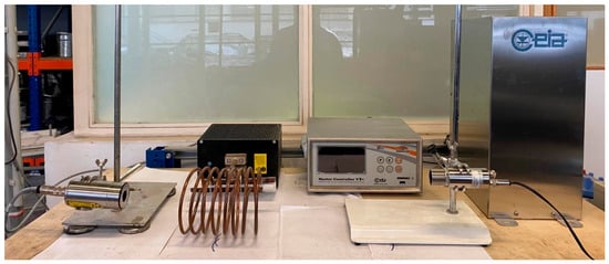
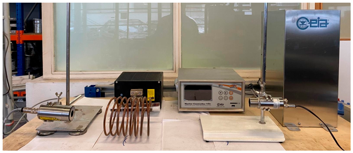
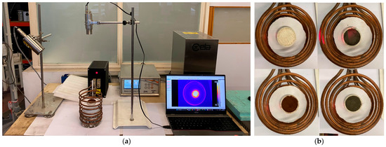
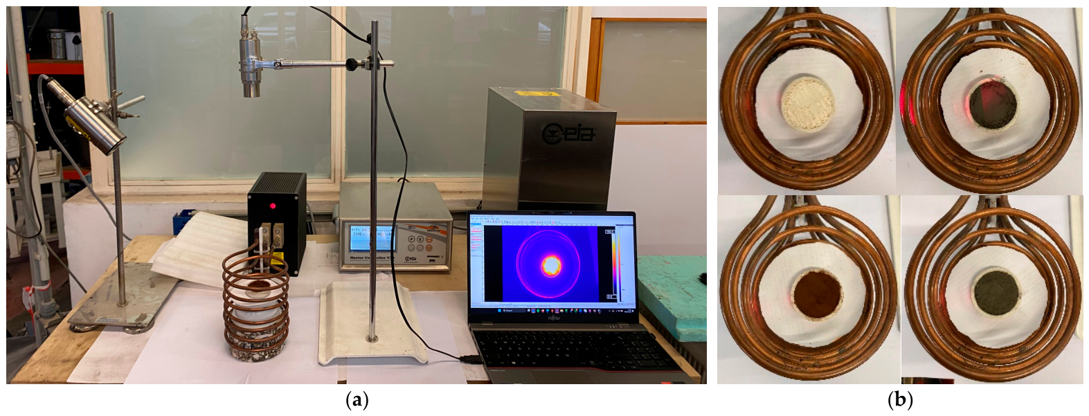
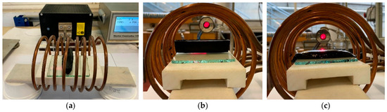
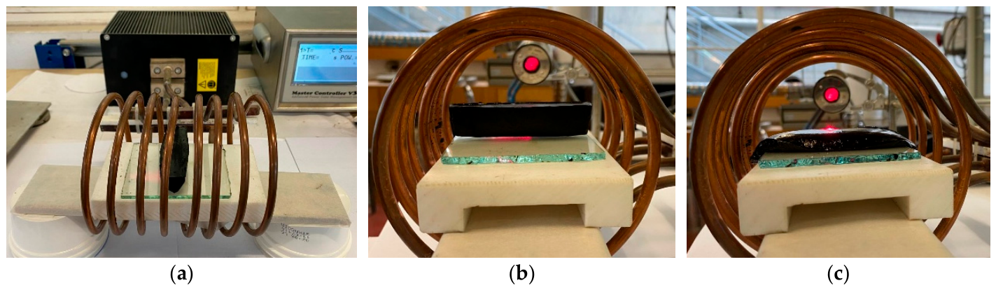
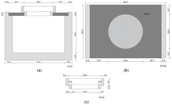
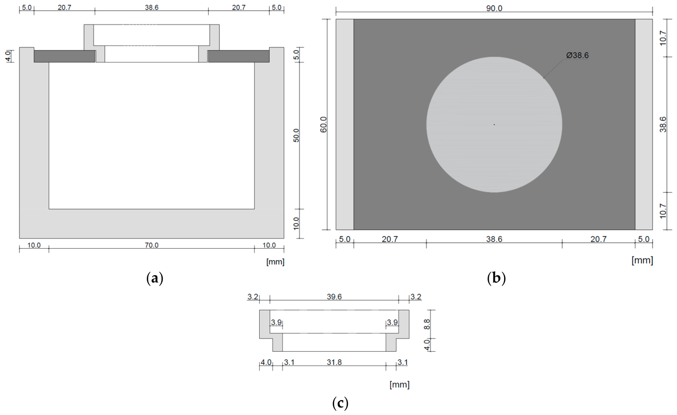
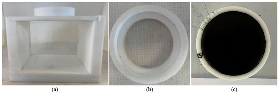
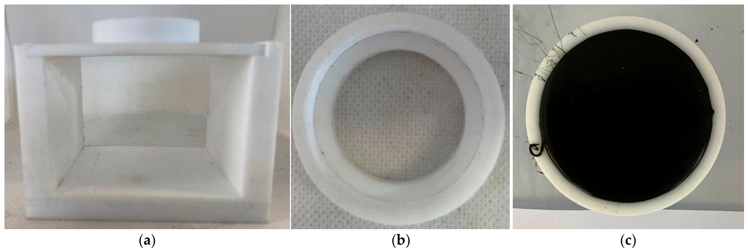
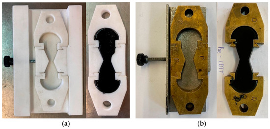
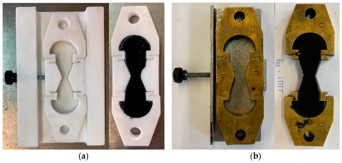


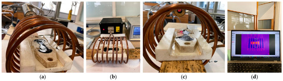
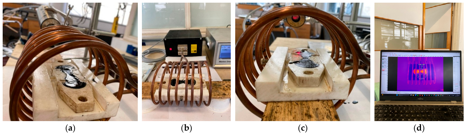
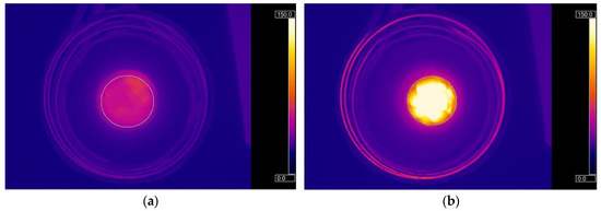
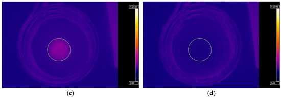
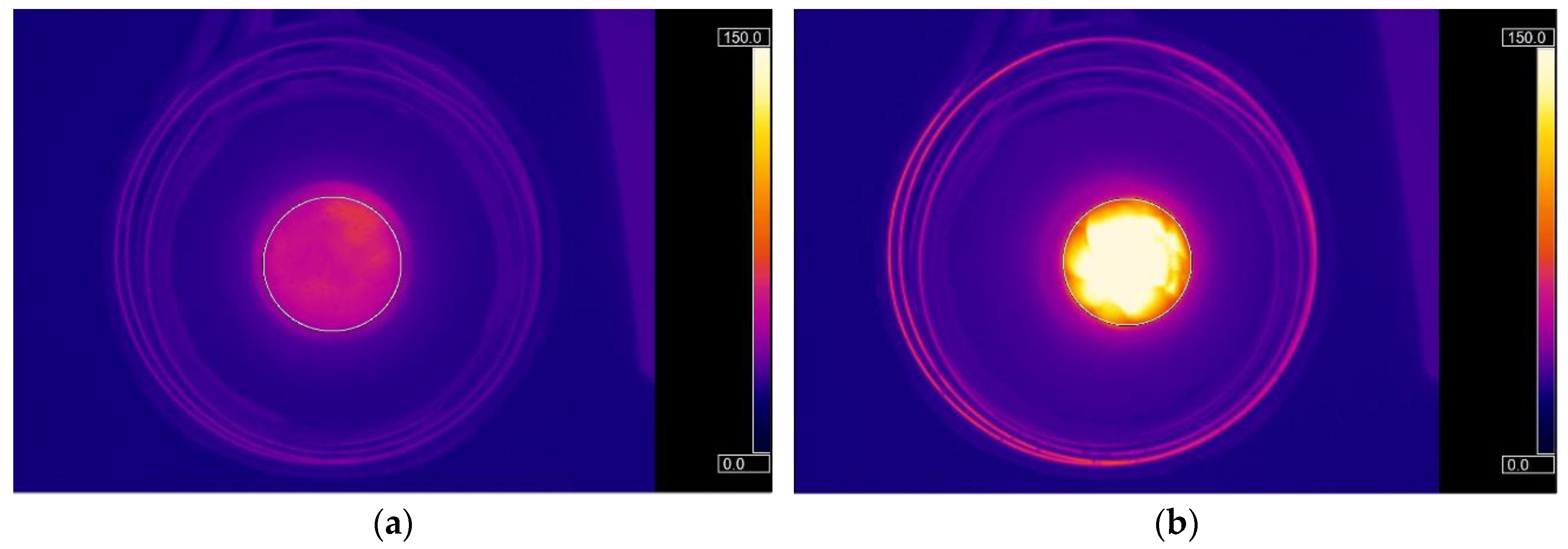
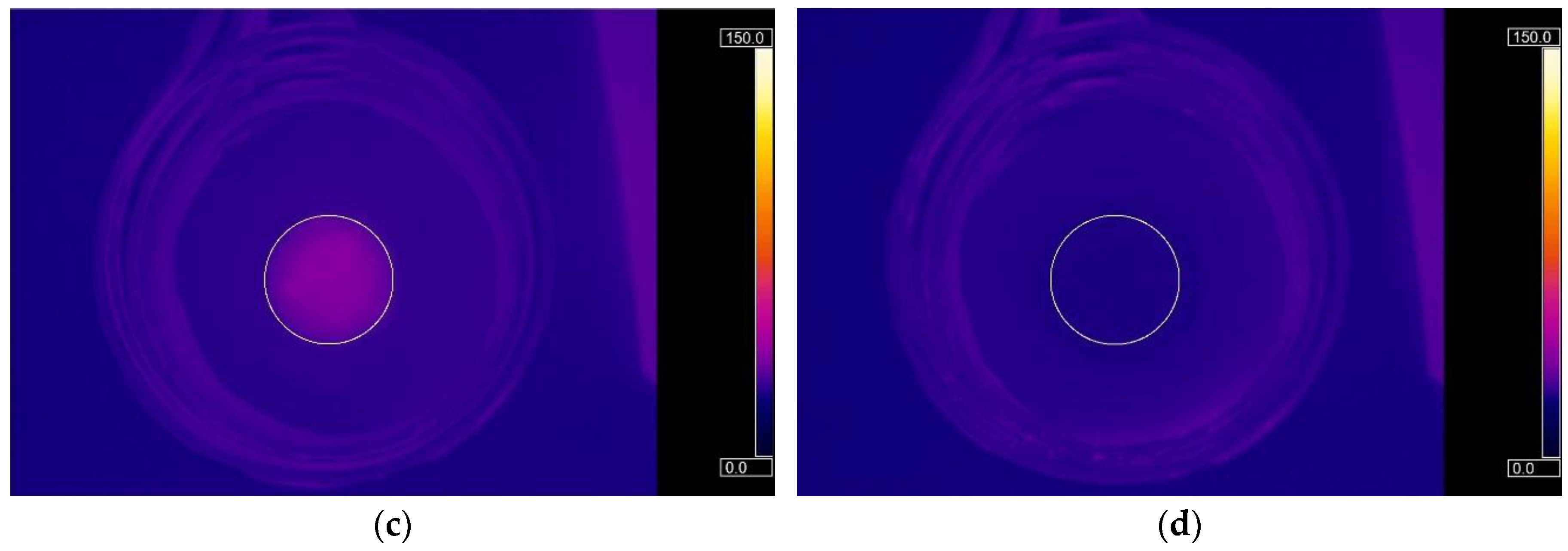
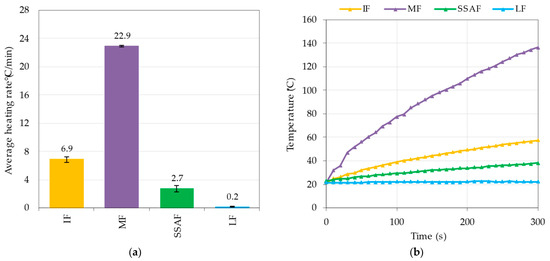
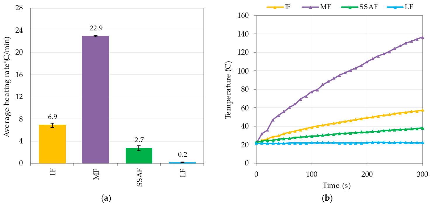
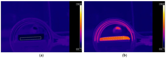
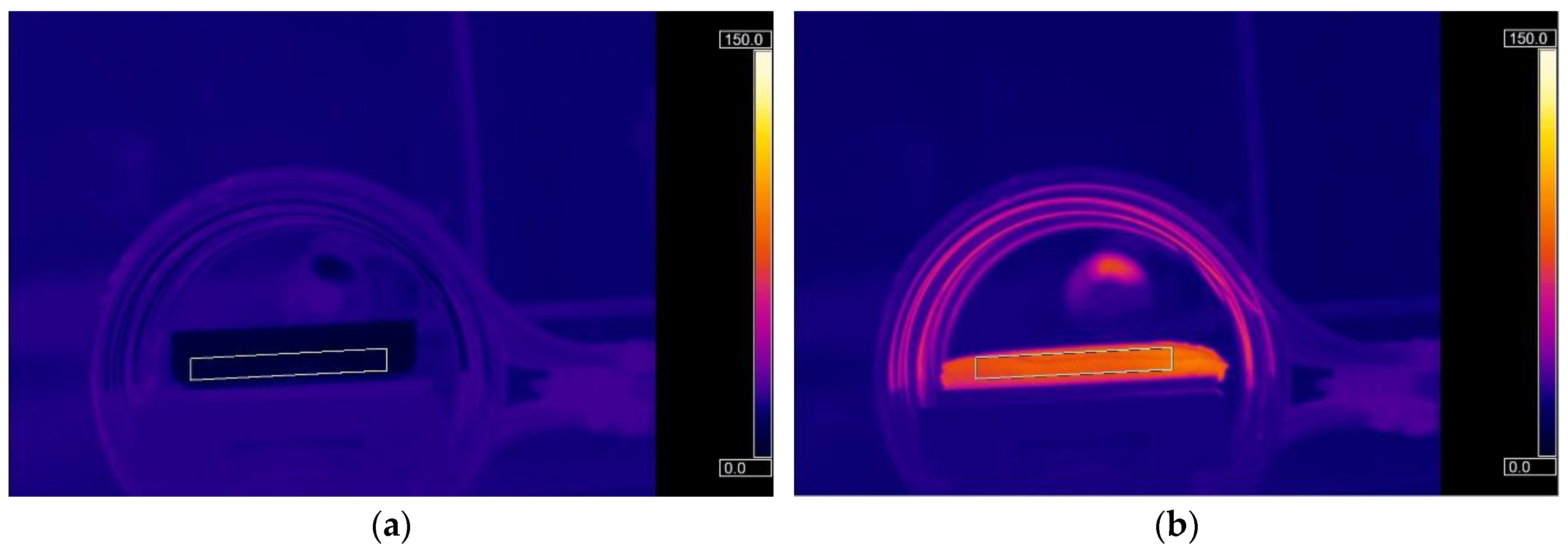
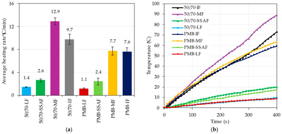
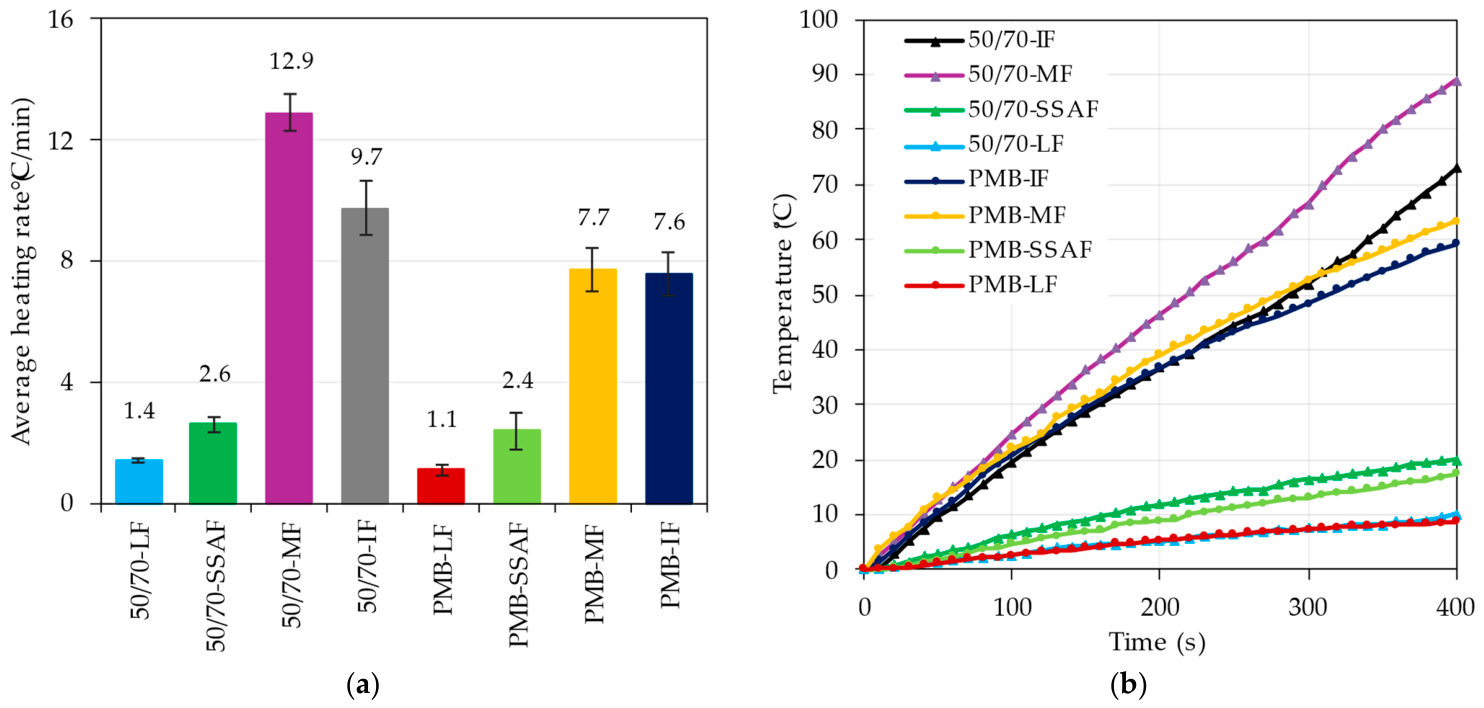
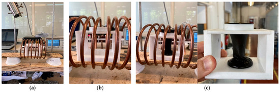
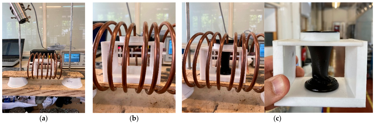
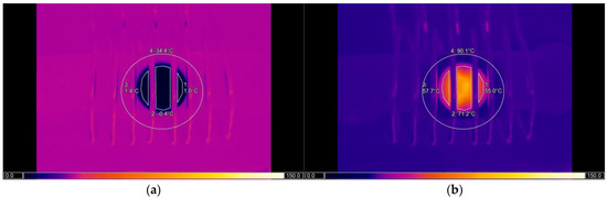
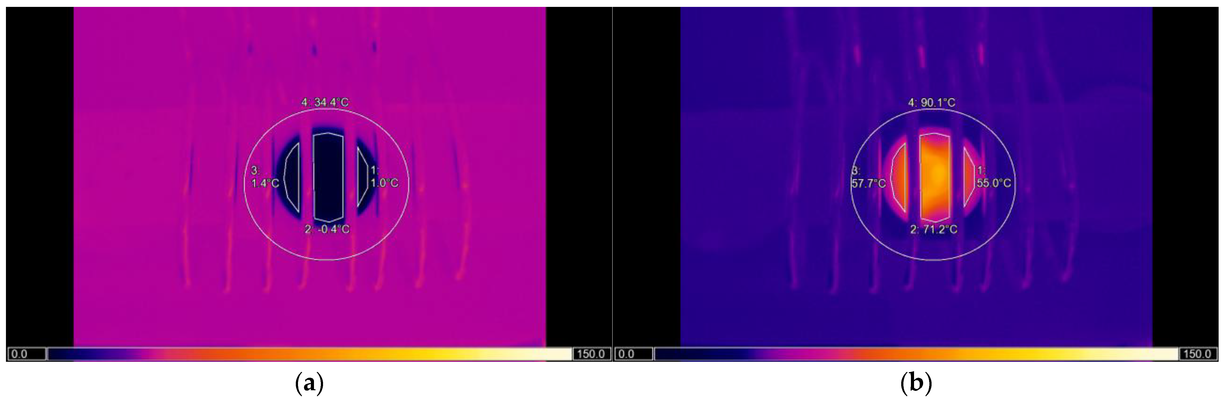
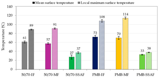
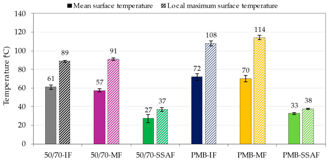
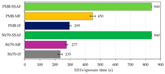
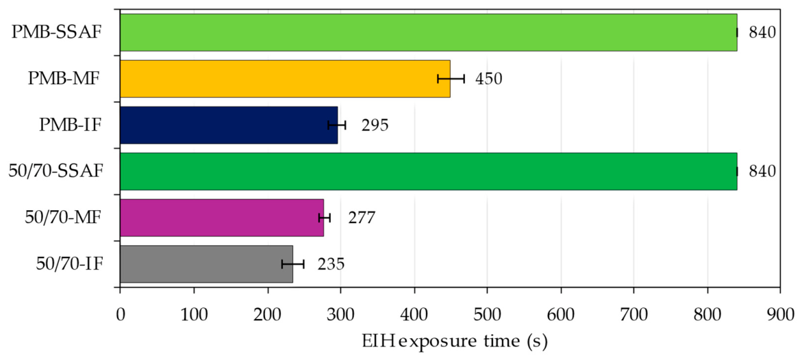
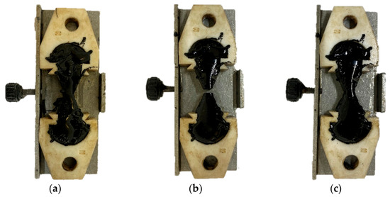
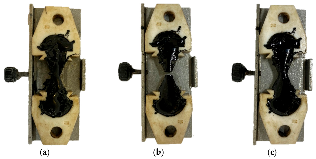
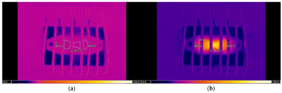
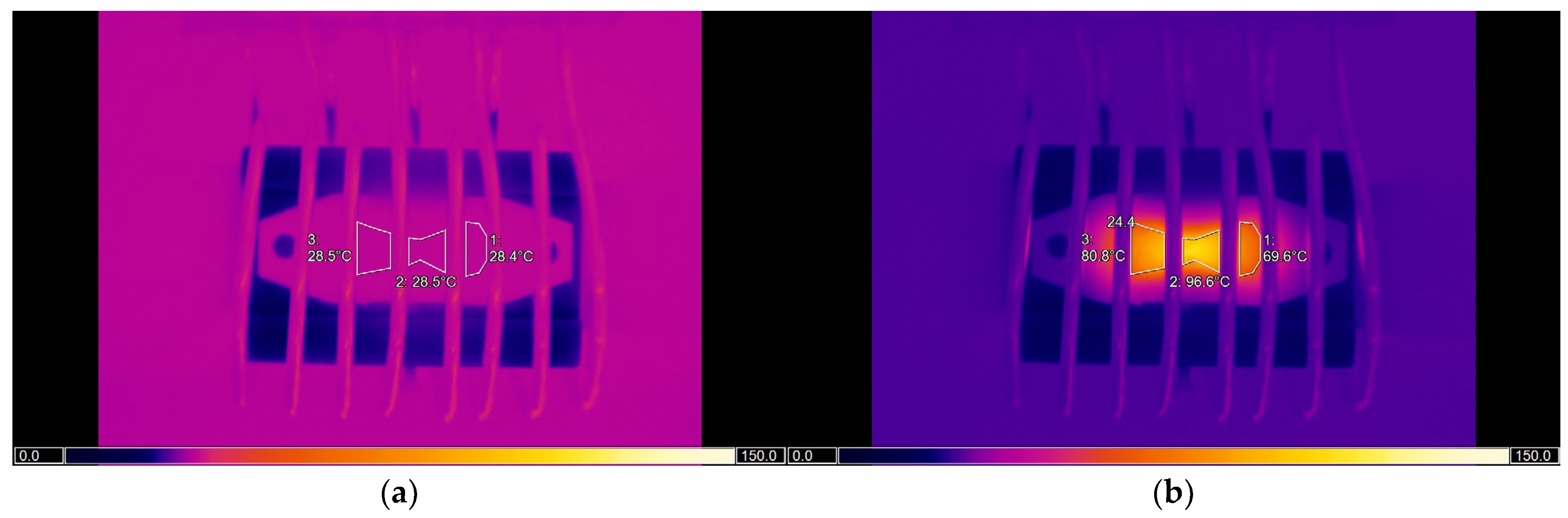
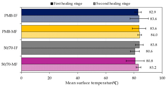
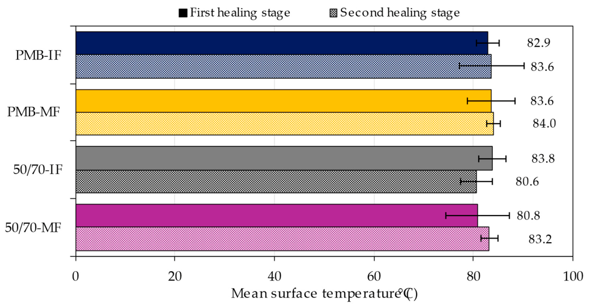
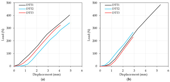
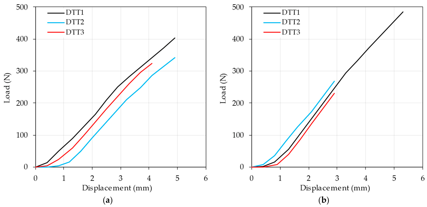
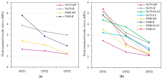
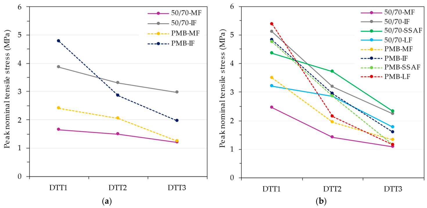
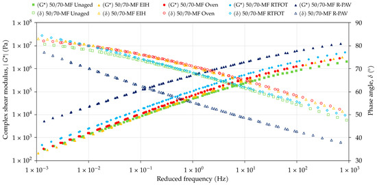
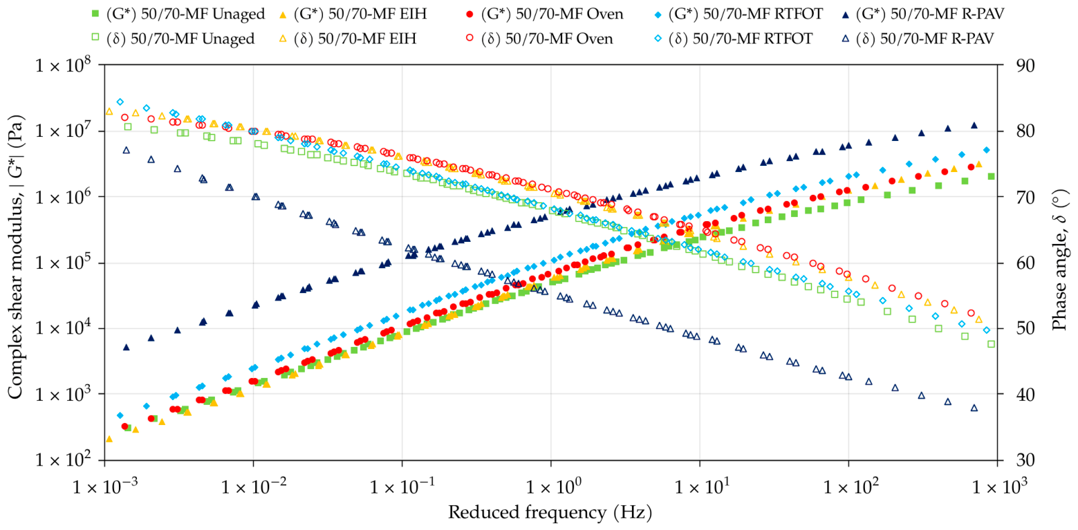
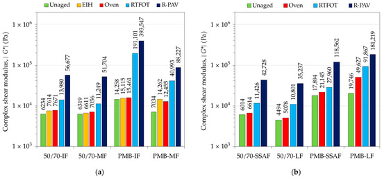
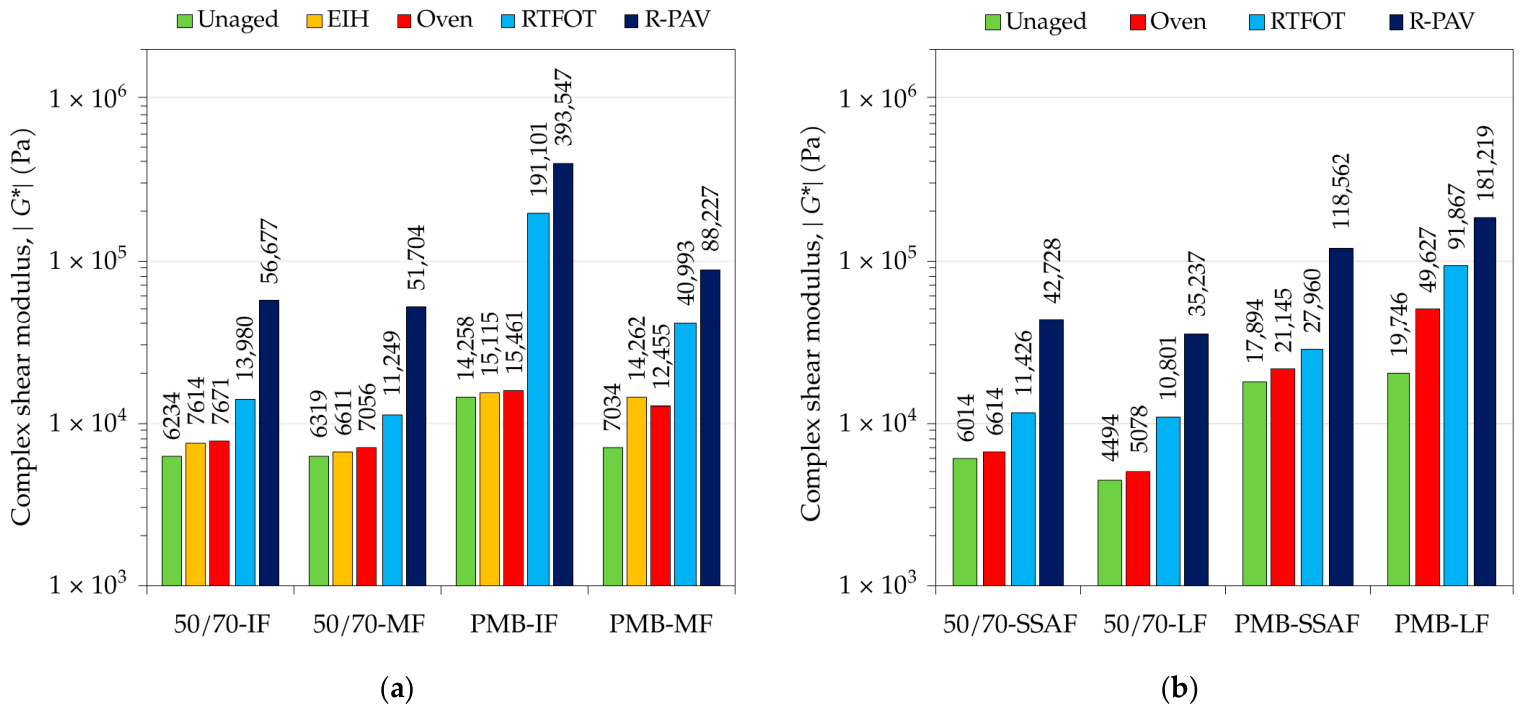
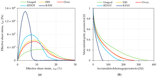
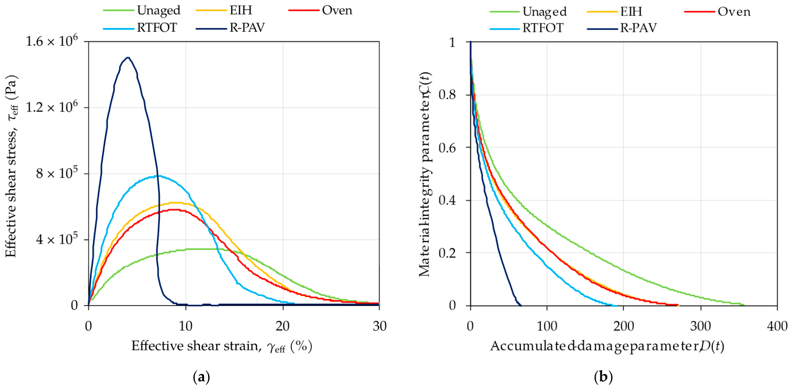
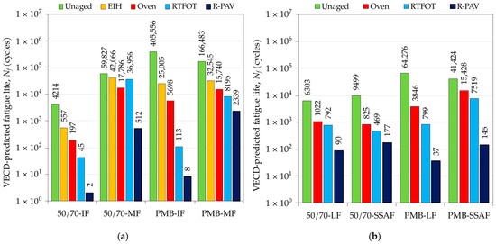
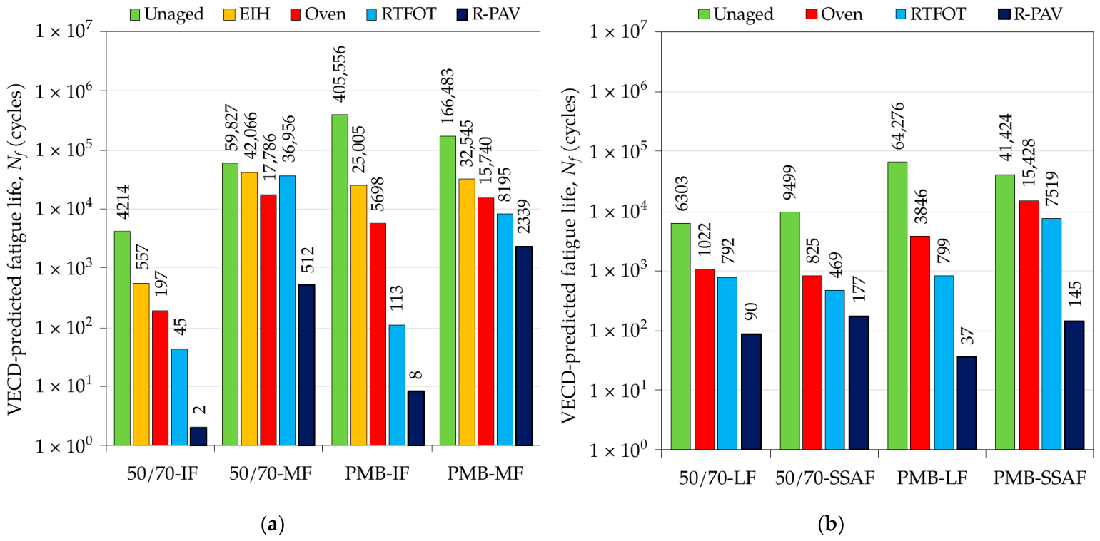
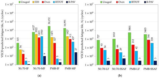
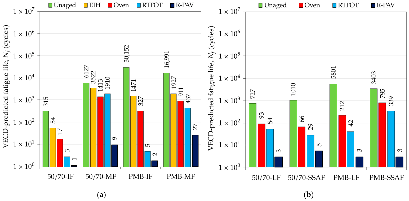

Disclaimer/Publisher’s Note: The statements, opinions and data contained in all publications are solely those of the individual author(s) and contributor(s) and not of MDPI and/or the editor(s). MDPI and/or the editor(s) disclaim responsibility for any injury to people or property resulting from any ideas, methods, instructions or products referred to in the content. |
© 2026 by the authors. Licensee MDPI, Basel, Switzerland. This article is an open access article distributed under the terms and conditions of the Creative Commons Attribution (CC BY) license.