


Abstract
This paper proposes a process-mapped quality control framework for structural steel fabrication as a proof of concept for integrating normative requirements into a unified operational workflow. The study addresses the fragmentation of quality requirements in steel fabrication, where individual standards are often applied through separate inspections rather than as part of a coherent process model. The framework links material control, production preparation, assembly, welding, and anticorrosion protection through clearly defined quality gates. The framework is constructed through a qualitative design-oriented approach using SIPOC analysis and a detailed flowchart. It translates normative requirements into a coherent workflow that provides a structured basis for traceability, preventive quality assurance, and future integration with Construction 4.0. The paper suggests that process mapping can serve as a useful method for organizing quality control in steel construction projects and for transforming standards into an operational framework.
1. Introduction
The construction industry operates within a highly regulated and technically complex environment where quality assurance is essential for structural safety, durability, and regulatory compliance. In structural steel fabrication, management is governed by extensive standards, including EN 1090-2 [1] for execution of steel structures, EN ISO 3834 [2] for welding quality requirements, and EN ISO 12944 [3] for corrosion protection systems. Although these standards comprehensively regulate specific technical domains, such as execution tolerances, welding quality, and corrosion protection, they address these areas separately and do not formalize their integration within a single, process-mapped operational structure.
Steel fabrication projects involve multiple interdependent phases, such as material procurement, cutting and forming, assembly, welding, and corrosion protection. Errors introduced in early stages can propagate downstream, causing costly rework, schedule delays, and reduced structural performance. Although normative compliance is mandatory, translating standard requirements into coherent production logic remains largely dependent on organizational practices. This dependency creates variability in quality outcomes and limits the proactive prevention of nonconformities.
Process mapping is a visual aid for picturing work processes, which shows how inputs, outputs, and tasks are linked [4]. Common process mapping techniques include basic flowcharts, detailed flowcharts, swimlane diagrams, value stream maps, and SIPOC diagrams (Suppliers–Inputs–Process–Outputs–Customers). Furthermore, ref. [4] emphasizes the importance of developing a critical process profile to clearly define process boundaries, input sources, outputs, and customers when constructing process maps. Process mapping has been widely recognized as an effective method for visualizing workflows, identifying bottlenecks, and improving operational efficiency [5,6]. However, within the context of steel fabrication, quality management has rarely been used to integrate normative requirements into structured quality control decision points. Existing research [7] typically addresses isolated aspects of fabrication, such as welding quality or corrosion protection, rather than the integrated fabrication continuum. Furthermore, research [8] emphasizes project planning/scheduling, while [5,6] focus on production optimization. The relationship between quality control and project defects is well-recognized [9], but without mapping these controls are directed towards specific fabrication workflows. Another study [10] provides a detailed structure of company and project quality systems in accordance with ISO 9001, but it does not develop operational production process mapping or define stage-specific control points, particularly for steel fabrication under European standards. Research [11] aligns most closely but lacks visual SIPOC, detailed process maps, and formalized quality gates that transform phase checks into auditable decision points.
The objective of this paper is to develop an integrated, process-mapped, fabrication quality framework for structural steel fabrication as a proof of concept, in which normative requirements are implemented through clearly defined quality gates at critical lifecycle transitions. The paper seeks to transform dispersed regulatory provisions into a coherent operational structure based on these quality gates. By linking material control, production preparation, assembly, welding, and anticorrosion protection into a unified process model, the proposed framework aims to enhance traceability, consistency, and preventive quality assurance in steel construction.
The originality of this paper lies in the development of a process-oriented quality control architecture that systematically integrates fragmented normative requirements into a unified operational workflow. The specific contributions can be summarized as follows:
- -
- Transformation of fragmented normative requirements into an integrated process model. Existing standards such as EN 1090-2, EN ISO 3834, and EN ISO 12944 define requirements for individual technical domains (execution, welding, and anticorrosion protection). However, they do not provide an integrated process structure showing when, where, and how these requirements should be verified throughout the fabrication workflow. The proposed framework introduces a continuous quality control pathway linking material receipt, production preparation, assembly, welding, and anticorrosion protection.
- -
- Introduction of quality gates as operational decision points. The framework contributes a structured mechanism that transforms conventional inspection activities into predefined release points. Each quality gate connects a fabrication stage with specific verification activities, acceptance criteria, documentation requirements, and corrective loops. This provides a process-based approach for preventive quality assurance rather than only post-process defect detection.
- -
- Integration of quality control, traceability, and documentation logic. Unlike conventional quality plans that often present inspection requirements as separate checklists, the proposed framework embeds traceability requirements within the fabrication sequence. The framework establishes logical links between material identification, fabrication operations, inspection results, and final compliance documentation.
- -
- Creation of a structured interface for Construction 4.0 implementation. The proposed framework provides a process layer that identifies where digital technologies can be applied. The contribution is not a digital tool itself, but a structured quality control architecture that enables systematic digitalization.
- -
- Development of a usable methodology for standards-based process modelling. The proposed framework demonstrate how complex normative requirements can be translated into SIPOC structures, detailed process maps, and quality decision points. This methodology can serve as a basis for future adoption, validation, and extension to other fabrication environments.
Following those guidelines, two research questions are formed:
Q1: To what extent can normative standards for structural steel fabrication be translated and integrated into a process-mapped quality control framework?
Q2: How can quality gates be embedded into the fabrication workflow to improve traceability and preventive quality assurance in steel construction projects?
Furthermore, the paper explores the compatibility of the framework with Construction 4.0 principles and how they are utilized within fabrication phases.
The paper is structured as follows: Section 2 presents the research methodology, including the normative framework analysis and the applied process mapping approach. Section 3 develops the integrated fabrication quality framework through SIPOC modelling and detailed flowchart decomposition. Section 4 discusses the validation, implications, limitations, and potential applications of the proposed framework within contemporary steel construction practice.
2. Research Methodology
2.1. Research Design
This paper adopts a qualitative, process-modelling research approach aimed at developing an integrated quality control framework for structural steel fabrication. Instead of quantitative performance measurement, the research focuses on the systematic integration of normative requirements into an operational process architecture. The methodological foundation combines the following:
- –
- Structured analysis of European normative standards governing steel fabrication;
- –
- Process mapping techniques (SIPOC and flowchart modelling);
- –
- Logical sequencing of fabrication activities;
- –
- Risk-oriented identification of decision points.
The research follows a design-oriented methodology, where the objective is to construct and iteratively refine a structured quality management model that can be applied in industrial practice.
Detailed flowchart modelling, quality gate selection, and process boundaries are applied to each fabrication stage according to EN 1090-2 (chapter 6: Preparation and assembly), where requirements for cutting, shaping, holing, and assembly are specified.
The proposed framework complements ISO 9001 by translating general process management principles into a fabrication-specific operational model [12]. While ISO 9001 defines the requirements for managing quality processes, the proposed framework identifies where and when quality verification should occur through predefined quality gates (QG1 to QG8). Therefore, it provides a detailed operational layer between a general quality management system and usual fabrication activities.
The proposed framework shares common principles with lean approaches, particularly the use of process mapping to visualize activities and identify critical control points. But the primary objective differs. While lean tools mainly focus on improving process efficiency and waste reduction, the proposed framework focuses on ensuring compliance, traceability, and prevention of quality failures. Quality gates provide potential integration points for lean analysis.
The proposed framework complements a BIM-based approach by providing the process structure into which BIM-based verification activities can be integrated. BIM models can support dimensional verification of fabricated elements through automated comparison between design geometry and manufactured elements (QG2), while assembly approval can be supported by BIM-based tolerance checking or augmented reality-assisted positioning (QG3).
Similar to risk-based inspection methods, the proposed framework adopts a preventive quality approach by identifying critical points where nonconformities may occur and establishing control mechanisms before defects propagate to subsequent stages. The proposed quality gates can provide a process structure for future risk-based prioritization. Integrating them with risk assessment methods could enable dynamic adjustment of inspection frequency and intensity according to project-specific conditions.
2.2. Normative Framework Analysis
The first methodological phase involved a structured review of relevant European standards governing steel fabrication. The analysis was focused on identifying control-related provisions, including inspection requirements, tolerance limits, qualification obligations, acceptance criteria, and documentation procedures. Relevant European standards applicable to structural steel fabrication were identified based on their relationship with EN 1090-2 execution requirements. Quality-related provisions were extracted, including requirements related to material identification and traceability, dimensional tolerances, welding procedures, inspection methods, acceptance criteria, and documentation. Extracted requirements were classified according to the corresponding fabrication stage: material procurement and storage, production preparation, assembly, welding, and corrosion protection. Identified requirements were translated into operational activities and assigned to specific quality gates within the process model. The principal standards are presented in Table 1.
Table 1.
Conducted European standards.
The normative review was limited to European standards directly related to the fabrication and quality control of structural steel components executed under EN 1090-2 (EXC1–EXC4). Standards primarily addressing structural design (e.g., Eurocodes) or other materials (such as concrete, timber, or aluminum) were not analyzed in detail, as they fall outside the scope of this paper. Consequently, the proposed framework is intended for application to steel fabrication processes and does not claim general validity for other structural materials or regulatory environments.
Outside the European regulatory environment, variations in fabrication standards, certification procedures, quality control criteria, and legal requirements can be significant. Consequently, the applicability and effectiveness of the proposed framework may be limited or require substantial adaptation to align with local regulations or industry practices outside the European Union. Users in non-European contexts should consider this limitation and validate or modify the framework on a case-by-case basis to ensure compliance with their respective regulatory environments and market conditions.
2.3. Process Mapping Method and Case Context
Process mapping was performed in two stages. First, a SIPOC analysis was used to define the macro-level structure of steel fabrication, identifying key process boundaries and interactions between stages. Second, detailed flowchart modelling was applied to each fabrication stage according to EN 1090-2 (chapter 6: Preparation and assembly), where requirements for cutting, shaping, holing, and assembly are specified. Each activity was decomposed into operational tasks, normative requirements, inspection actions, decision points, and corrective loops. Quality gates were introduced as formal decision nodes representing mandatory compliance verification before transition to subsequent stages. The developed framework was structured according to typical steel fabrication workflows in projects such as building frames, industrial halls, and similar steel structures executed under EN 1090-2, including multiple execution classes (EXC1–EXC4). The framework reflects the organization of a typical certified steel fabrication workshop. Although the framework is not derived from a single detailed case study, its sequencing, roles, and control points were aligned with common industry practice for medium- to large-scale steel fabrication projects. As a result, the case context can be described as a generic, but practically oriented, representation of steel fabrication workflows in the European regulatory environment. The fabrication stages that were analyzed include:
- Material procurement and storage;
- Production (cutting, shaping, and holing);
- Assembly;
- Welding;
- Anticorrosion protection.
The framework was developed iteratively through alignment between normative requirements, practical fabrication sequencing, and risk-based identification of defect points. At each stage, potential nonconformity (NCR) sources were analyzed, and inspection activities were repositioned as decision-based release mechanisms. Corrective loops were embedded to prevent downstream error escalation. The final result is a continuous, stage-based quality control architecture integrating normative compliance within a structured operational workflow.
3. Development of the Integrated Fabrication Quality Framework
This section presents the application of process mapping techniques to the steel construction project lifecycle through the development of a SIPOC diagram and detailed process flowcharts. The SIPOC diagram defines system boundaries and core flows, while the subsequent flowcharts specify activities, decision points, and quality gates. Although construction projects use different materials (e.g., concrete, timber, or aluminum) that require compliance with different standards, the general structure of the SIPOC diagram remains largely consistent across different material types.
3.1. SIPOC Mapping
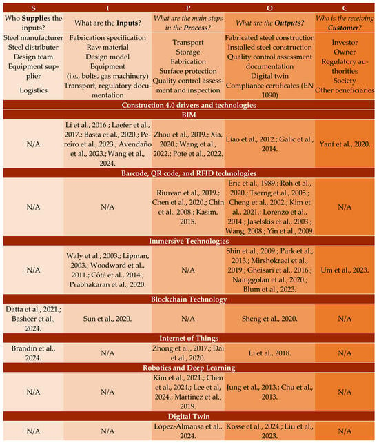
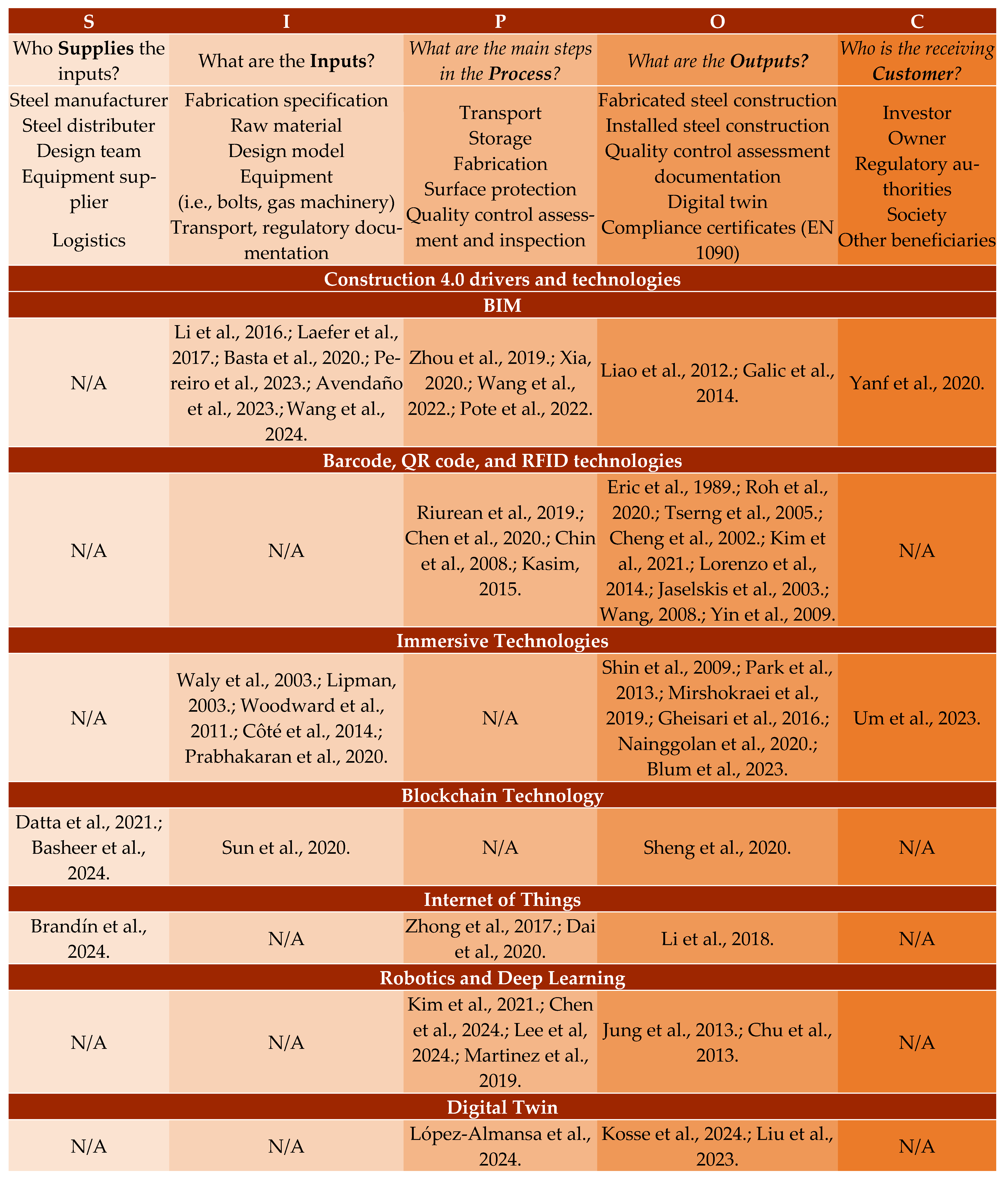
The SIPOC diagram consists of five key elements: Suppliers (S), Inputs (I), Processes (P), Outputs (O), and Customers (C). Figure 1 presents the SIPOC diagram that retains the core structure of the process model while mapping relevant Construction 4.0 technologies to the corresponding SIPOC stages identified in the literature. The diagram illustrates how digital technologies are distributed across the project lifecycle, from suppliers and inputs to process activities, outputs, and customer-related functions. This extended view provides a conceptual basis for examining where specific technologies are most frequently applied and how they may support quality control in steel construction.
Figure 1.
SIPOC diagram for steel construction project: boundaries, key stakeholders, and structural relationships [18,19,20,21,22,23,24,25,26,27,28,29,30,31,32,33,34,35,36,37,38,39,40,41,42,43,44,45,46,47,48,49,50,51,52,53,54,55,56,57,58,59,60,61,62,63,64,65,66,67,68,69,70,71,72].
The purpose of the SIPOC diagram is to define the project boundaries, identify key stakeholders, and establish the structural relationships between inputs, operational activities, and deliverables before proceeding to detailed process decomposition presented in flowcharts.
Within the SIPOC framework, Suppliers and Inputs are directly linked to the Process element, which, in the context of steel construction, is primarily associated with fabrication and related manufacturing activities. In this paper, this process corresponds to steel manufacturers that execute steel structures under EN 1090-2, with welding quality controlled in accordance with EN ISO 3834 and EN ISO 5817, and corrosion protection governed by EN ISO 12944 and EN ISO 14713. It should be noted that each supplier operates its own internal processes, which are subject to separate quality control procedures. Once individual processes are completed and verified, the resulting outputs are generated. The outputs of the steel construction process include fabricated structural elements, which are subsequently transported, stored on-site, and installed. Following installation, comprehensive quality control inspections and documentation are conducted to verify compliance with applicable standards and project specifications. Upon completion of these activities, the project is formally handed over to the customer.
Due to the high-level nature of the SIPOC diagram, particular attention must be paid to the definition and conciseness of the Process element. To achieve a more detailed understanding of individual activities and quality control requirements, the main process identified in the SIPOC diagram is further analyzed using detailed flowcharts. These flowcharts explicitly incorporate quality control stages, inspection points, and decision-making steps for each process.
3.2. Flowchart Diagram of Process
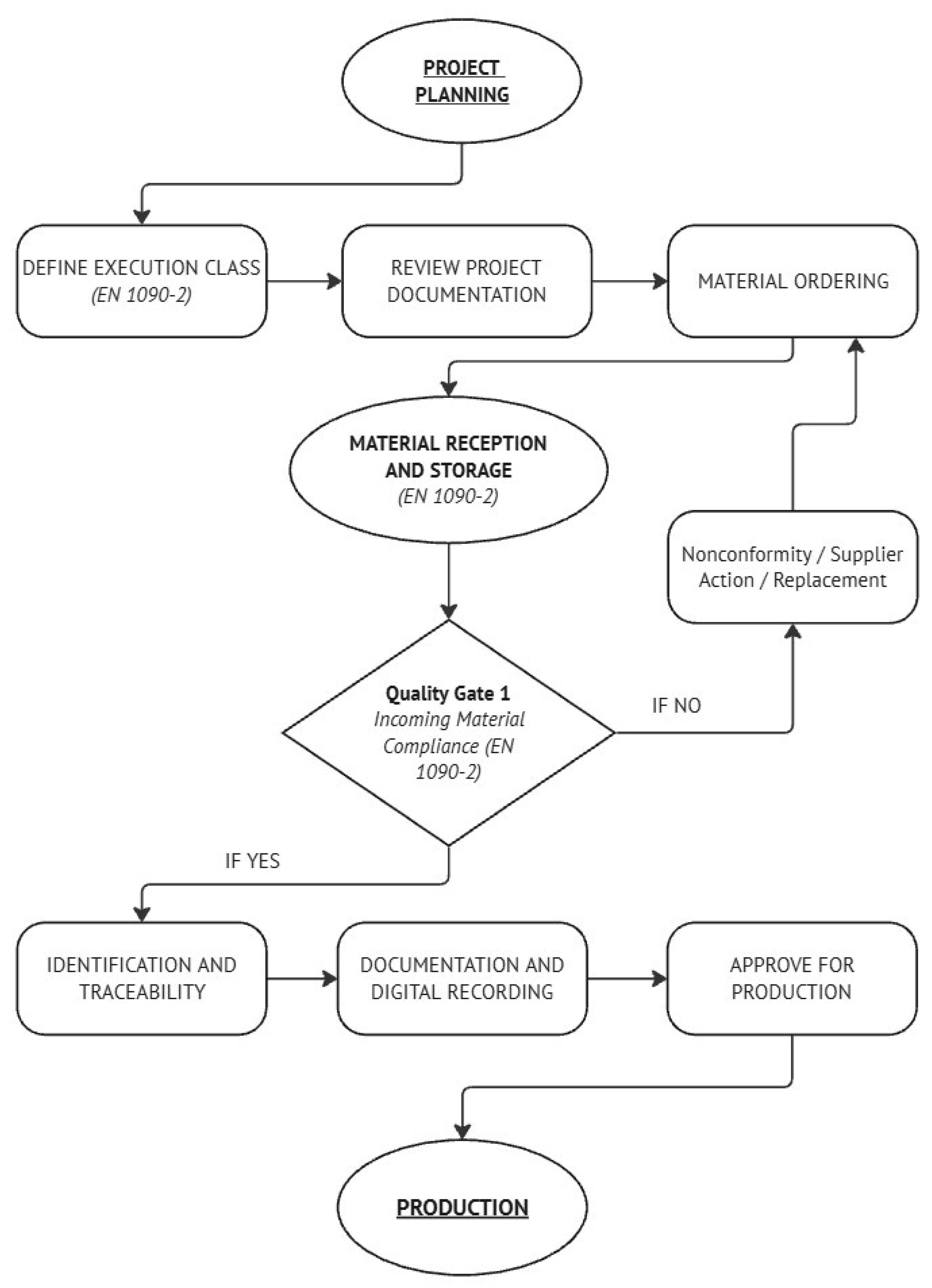
This section presents a detailed flowchart diagram for the processes extracted from the SIPOC analysis within the Process stage. The flowchart illustrates each step of steel manufacturing together with the corresponding quality control activities. Furthermore, for each purpose, the relevant requirements of EN 1090-2 are examined in order to define production tasks and quality measures aimed at minimizing errors and nonconformities. Prior to material delivery to the manufacturer’s storage facility, it is essential to define the execution class (EXC) of the structure based on the project requirements and building purpose. Subsequently, a detailed review of project documentation is carried out to determine the required steel grades and material quality. Based on this information, materials are ordered from the steel supplier. During the ordering process, the manufacturer is responsible for ensuring that material certificates are provided by the supplier in order to verify the mechanical properties and compliance of the steel. Those initial processes are part of project planning.
3.2.1. Material Storage
Material storage, identification, traceability, and recording play a crucial role in effective material management, project documentation, and material certification upon completion of the project. Furthermore, this stage ensures that only verified and traceable materials enter the production process in accordance with EN 1090-2 and related normative requirements. Upon delivery to the manufacturer’s facility, the material storage process formally begins with unloading and segregation of the delivered profiles and plates. At this point, Quality Gate 1—Incoming Material Compliance Verification is initiated. This gate includes systematic inspection activities designed to confirm conformity with contractual and normative requirements. The following checks are performed:
- Verification of steel grade against project documentation;
- Confirmation of the heat number stamped on the material;
- Comparison of the delivered material with the corresponding inspection certificate;
- Verification of mechanical properties such as yield strength and tensile strength;
- Quantity control against delivery documentation.
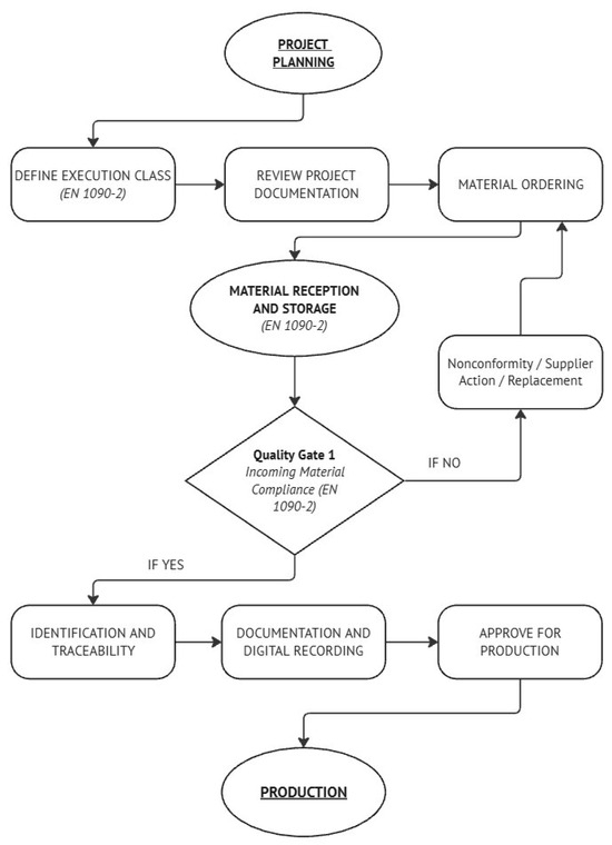
If discrepancies are identified, the material is classified as nonconforming, segregated from approved stock, and subjected to corrective action, which may include supplier notification or return of goods. Following successful verification, traceability, documentation, and digital recording are implemented. Primarily, the heat number provided by the supplier is recorded in internal documentation systems, ensuring continuous linkage between the physical material and its certification. In many cases, the manufacturer assigns an internal identification number while preserving the original heat number reference. This procedure guarantees traceability throughout cutting, welding, inspection, and final documentation stages. Once identification and documentation activities are completed, the material is formally released to subsequent fabrication stages, such as cutting, holing, and shaping. In this manner, material storage functions not merely as a logistical operation but as the foundational quality control checkpoint that safeguards the integrity of the entire steel fabrication process. Complete map processing in the form of a flowchart is illustrated in Figure 2.
Figure 2.
Quality Gate 1—Project Planning and Material Storage.
3.2.2. Production—Cutting, Shaping, and Holing
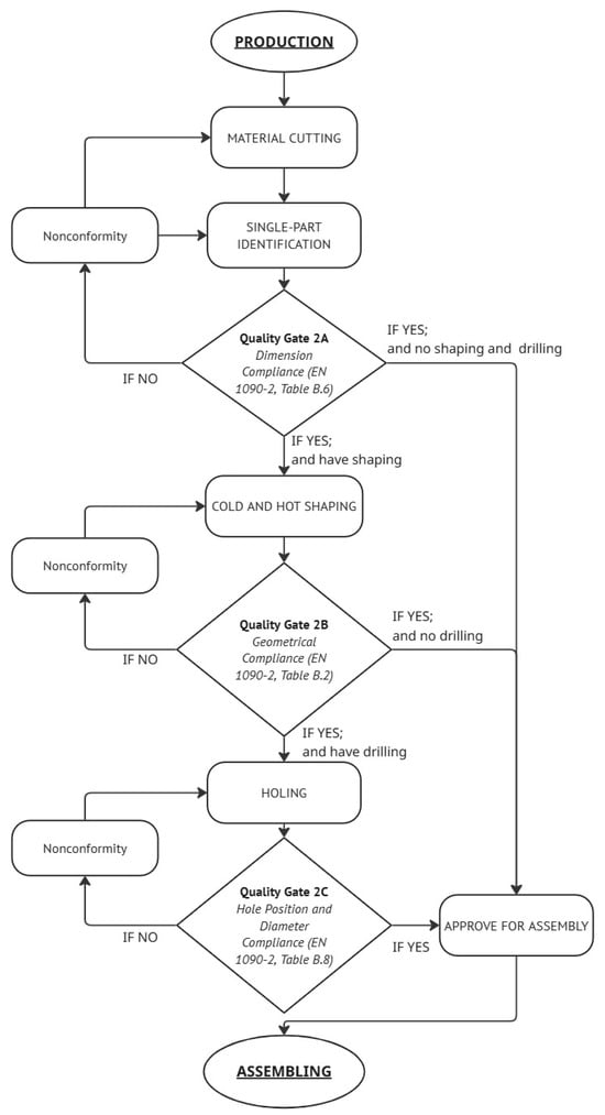
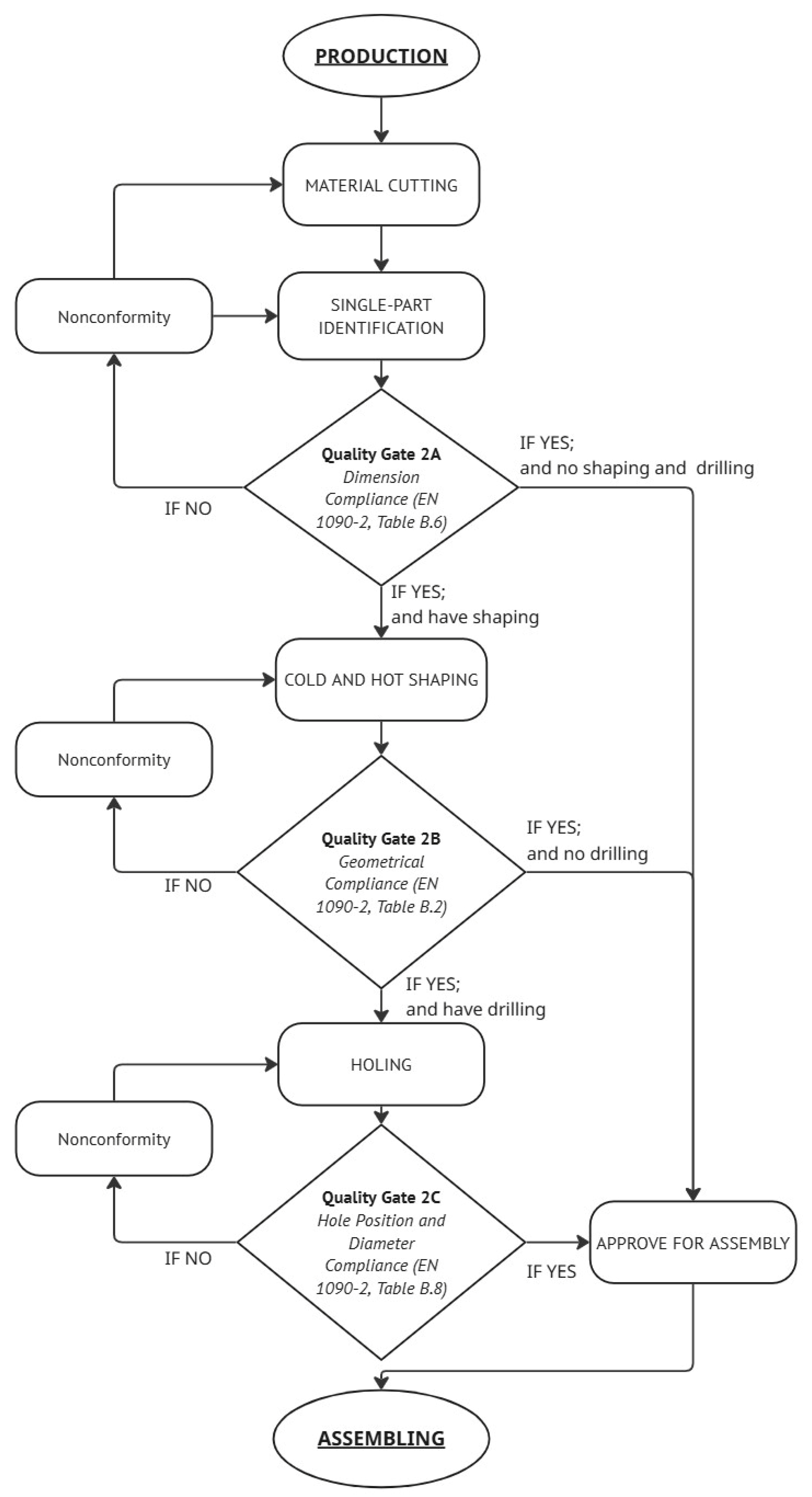
Following material approval at Quality Gate 1, the production phase begins with material preparation, consisting of cutting, shaping, and holing operations. These processes represent a geometrically critical stage, as dimensional inaccuracies directly influence assembly alignment, welding quality, and overall performance. Complete map processing is illustrated in Figure 3.
Figure 3.
Quality Gate 2—Cutting, Shaping, and Holing.
Material Cutting
Cutting is the first manufacturing operation and may be performed using various techniques, including mechanical cutting, plasma cutting, or flame cutting, depending on available equipment and material thickness. Regardless of the method employed, dimensional tolerances must comply with EN 1090-2, Annex B, Table B.6, which defines permissible deviations for cut lengths, straightness, squareness, and edge quality. Following cutting, individual components are marked with identification codes to ensure traceability throughout subsequent fabrication stages. Offcuts and remaining material are returned to storage and recorded for potential reuse. Compliance with dimensional requirements is verified at Quality Gate 2A—Dimensional Compliance. If deviations exceed allowable tolerances, the component is directed to a nonconformity and rework procedure. Only compliant elements proceed to the shaping phase.
Material Shaping (Cold and Hot Forming)
Where required by design documentation, steel elements undergo shaping operations. Cold forming is typically applied to plates and thin profiles, while hot forming may be used for complex geometries or notching operations in accordance with workshop drawings. Dimensional tolerances for formed steel elements must comply with EN 1090-2, Table B.2. Improper forming may introduce residual stresses or distortions that compromise assembly accuracy. Compliance is verified at Quality Gate 2B—Geometrical Compliance. Nonconforming elements are returned for corrective action, ensuring that only geometrically compliant components advance to the holing stage.
Material Holing
Holing represents the final operation within material preparation. Holes may be produced manually or through CNC machining during cutting. The accuracy of hole diameter, spacing, and positioning is particularly critical, as these features directly affect structural connections. Tolerances for holes are specified in EN 1090-2, Table B.8 Manufacturing tolerances—Fastener holes, holes and cut edges. Deviations at this stage may lead to installation difficulties and forced assembly, which can negatively affect structural integrity. Verification is conducted at Quality Gate 2C—Hole Position and Diameter Compliance.
Following successful verification at all three quality gates, steel elements are formally approved for assembly. Documentation and digital records are updated to maintain full traceability from incoming material through production preparation. By structuring cutting, shaping, and holing operations into sequential quality gates with defined decision points and rework loops, the production stage shifts from reactive defect correction to proactive dimensional control. This approach enhances process transparency, reduces downstream nonconformities in welding and assembly, and strengthens the overall fabrication quality management system.
3.2.3. Assembly and Assembly Control
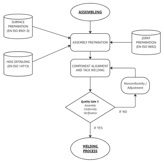
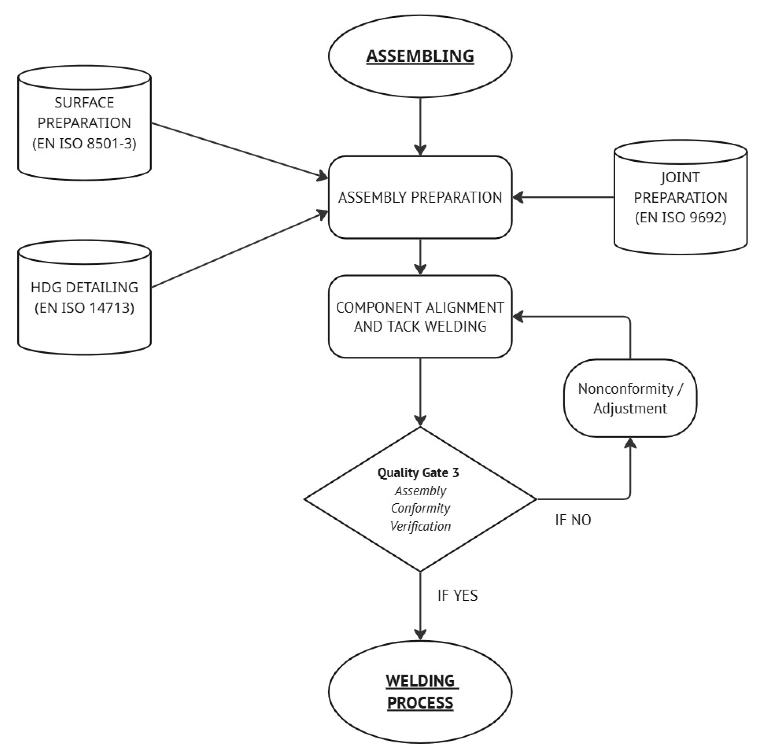
Assembly represents a critical transitional stage between material preparation and welding. At this stage, individually fabricated components are positioned, aligned, and temporarily fixed (tack weld) to form structural subassemblies in accordance with workshop documentation and the dimensional tolerances defined in EN 1090-2 Annex B. Due to the predominantly manual nature of assembly operations, this stage introduces a significant risk of geometric deviation and welding preparation errors. The assembly process is divided into two stages—(1) component preparation and (2) component alignment and tack welding—which are described as follows.
Component Preparation
Prior to component alignment and tack welding, assembly preparation is carried out. In practice, several preparatory activities occur in parallel and are completed before final inspection of the assembled elements. These include:
- Surface preparation for welding, in accordance with EN ISO 8501-3, ensuring that areas adjacent to weld zones are free from contaminants and unsuitable surface conditions;
- Joint preparation, in compliance with EN ISO 9692, including verification of bevel geometry, root gaps, edge preparation, and accessibility for welding;
- Hot-dip galvanization (HDG) detailing, in accordance with EN ISO 14713, where applicable, including the provision of drainage and vent holes as well as necessary profile cut-outs to ensure proper zinc flow and prevent coating defects.
These activities are not inspected as isolated control points. Instead, they form an integrated preparatory stage whose conformity is verified collectively after the element has been fully assembled. Particular attention must be given to HDG detailing, as inadequate drainage or venting may result in significant defects during the galvanizing process. Such requirements are not always explicitly detailed in workshop documentation and therefore require proactive verification during the assembly phase.
Component Alignment and Tack Welding
Following preparation, components are positioned and aligned according to workshop drawings. Dimensional accuracy, geometric tolerances, and spatial orientation must comply with EN 1090-2 (Annex B). Adjustments are performed as necessary before temporary fixation. Once correct positioning is achieved, components are secured by tack welds. Tack welding must ensure sufficient stability to maintain alignment during subsequent welding operations without introducing excessive restraints or distortion. Because alignment, joint preparation verification, and HDG detailing adjustments occur in close succession and often iteratively, the assembly process is practically completed before formal inspection takes place. Therefore, inspection is performed on the completed assembled element rather than at the intermediate stage. Upon completion of assembly and tack welding, the element is subjected to Quality Gate 3—Assembly Approval. This gate verifies:
- Geometrical compliance with EN 1090-2 (dimensional tolerances and fit-up);
- Proper execution of joint preparation in accordance with EN ISO 9692;
- Adequate surface condition in weld areas as defined in EN ISO 8501-3;
- Compliance of HDG detailing with EN ISO 14713, where galvanization is specified.
If nonconformities are detected, corrective actions or rework are undertaken. Only after successful approval at Quality Gate 3 may the element process to the welding process.
It can be noted that assembly inspection remains labour-intensive and susceptible to operator-dependent variability. Emerging Construction 4.0 technologies offer potential enhancements through digital measurement systems, laser scanning, and augmented reality-assisted alignment verification. These technologies enable real-time geometric comparison between the physical assembly and digital design models, improving inspection accuracy and documentation traceability. Following successful completion of Quality Gate 3, the assembly is formally approved and transferred to the welding stage, where process-specific quality gates are implemented. The assembling process map is presented in Figure 4.
Figure 4.
Quality Gate 3—Assembly Phase.
3.2.4. Welding and Welding Control
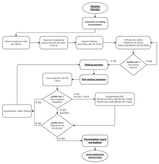
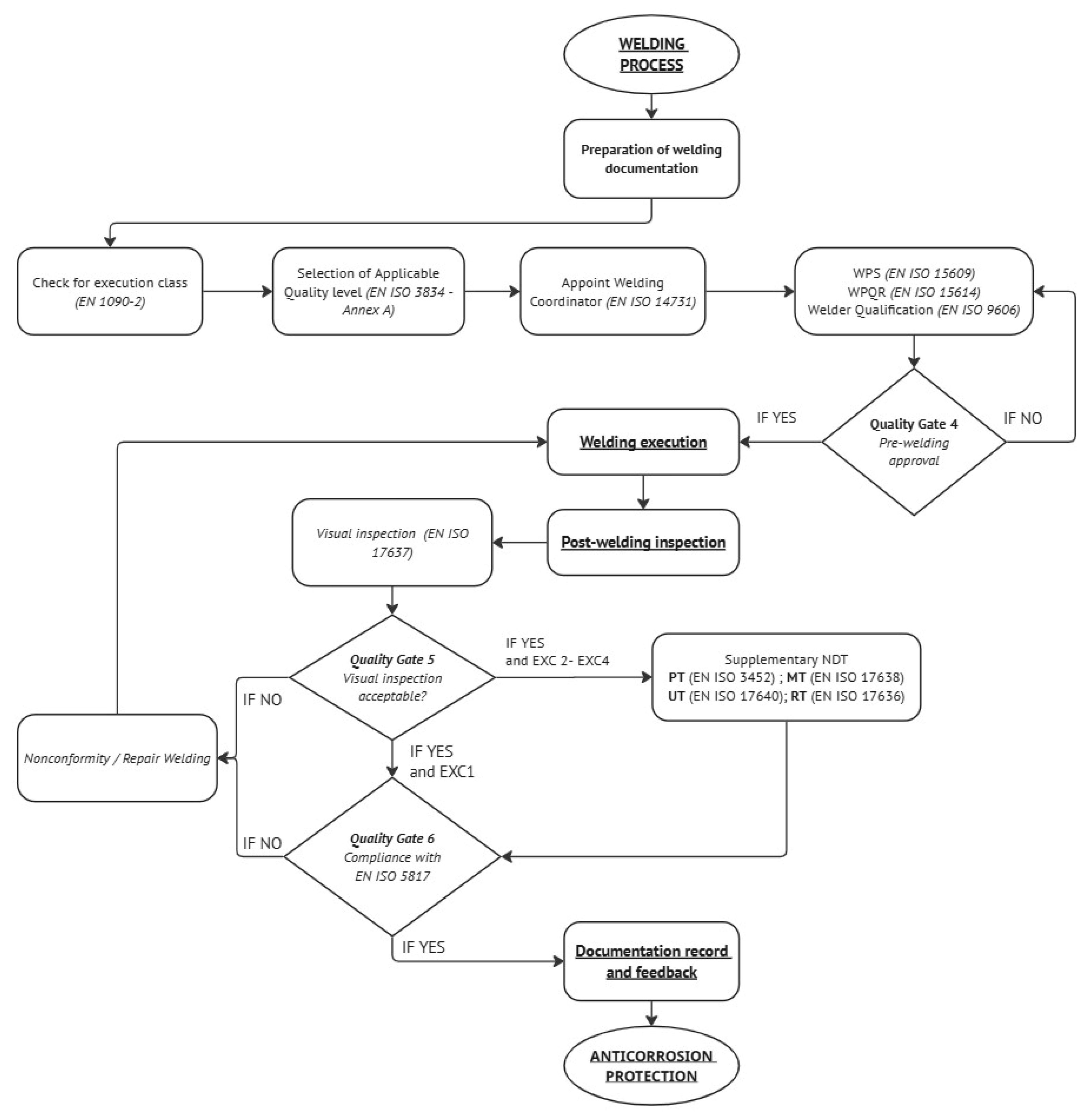
Welding represents one of the most critical and time-consuming operations in steel fabrication. The more complex the assembly, the more time-consuming welding becomes. The complexity and duration of welding activities increase proportionally with the geometric and structural complexity of the assembly. Moreover, welding is a quality-critical and largely irreversible process; defects detected at later stages may result in costly repairs, delays, or structural compromise. The regulatory framework governing welding is extensive and distributed across multiple standards. However, since this research focuses on process mapping as a tool for quality control enhancement, only standards directly related to quality assurance are considered in this section (Table 2). From a process mapping perspective, the welding operation can be structured into four principal phases: (1) preparation of welding documentation, (2) welding execution, (3) post-weld inspection, and (4) documentation record and feedback. Each of the four phases contains structured inspection checkpoints, defined in this paper as Quality Gates, which are illustrated in Figure 5 and explained further in this section.
Table 2.
Relevant quality control welding standards used in process mapping.
Figure 5.
Quality Gates 4, 5, and 6—Welding Process.
Pre-Welding Quality Assurance
The EN ISO 3834 series establishes graduated quality requirements for welding, enabling the level of control to be aligned with the execution class (EXC) and associated structural risk. The selected EN ISO 3834 level directly determines the number and strictness of quality control measures incorporated into the welding process map (Table 3). Manufacturing should be aware of the appropriate quality level before welding execution begins; normally it is determined in early project stages. Additionally, the appointed Welding Coordinator (EN ISO 14731) prepares and approves the Welding Procedure Specification (WPS) in accordance with EN ISO 15609 and verifies the Welding Procedure Qualification Record (WPQR) according to EN ISO 15614. Welder qualification is ensured in accordance with EN ISO 9606-1. These activities form Quality Gate 4—Pre-welding Approval, which ensures that all procedural and personnel requirements are satisfied before welding execution begins.
Table 3.
EN ISO 3834 comparison.
Welding Execution and Inspection
Following approval, welding is performed in accordance with the validated WPS by qualified welders. All welds are subjected to 100% visual inspection in accordance with EN ISO 17637, with inspection extent defined by EN 1090-2 regarding the NDT control. This stage represents Quality Gate 5—Visual Inspection Acceptance, where visible imperfections are assessed before further inspection procedures are initiated. Depending on the EXC, supplementary non-destructive testing (NDT) may be required. Applicable methods—such as penetrating testing (EN ISO 3452), magnetic particle testing (EN ISO 17638), ultrasonic testing (EN ISO 17640), and radiographic testing (EN ISO 17636)—are determined by the Welding Coordinator.
Final Acceptance and Documentation
Inspection results are evaluated in accordance with EN ISO 5817, which defines acceptance levels for weld imperfections. This constitutes Quality Gate 6—Compliance with EN ISO 5817, where a formal decision is made regarding weld acceptance or need for repair. If nonconformities are identified, repair welding is performed and the inspection process is repeated. Upon successful compliance, inspection records, weld maps, and traceability documentation are completed.
The structured integration of these three quality gates transforms welding quality management from a reactive defect-detection approach into a proactive and systematically controlled process. The inclusion of explicit decision points and rework loops enhances traceability, reduces variability, and ensures compliance with EN 1090-2 and EN ISO 3834 requirements. The complete welding process map is presented in Figure 5.
3.2.5. Anticorrosion Protection
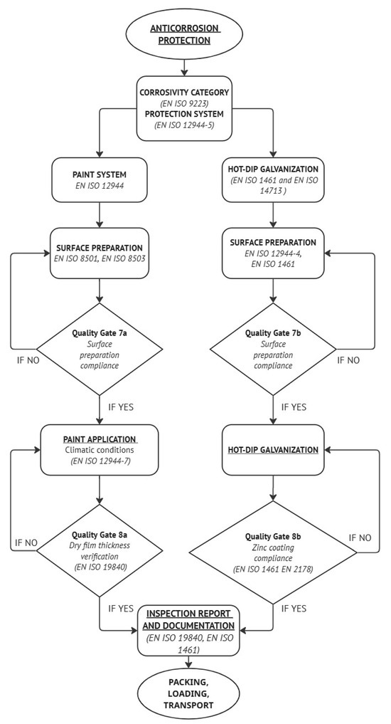
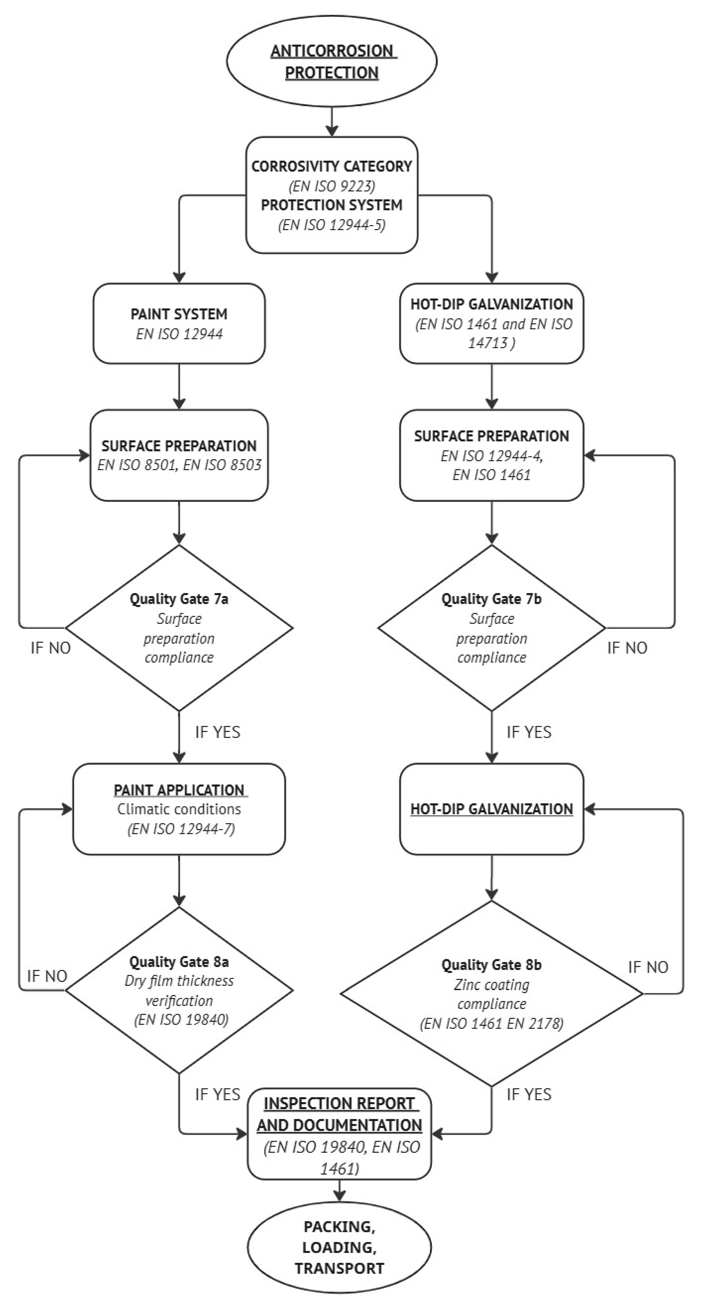
The paint system represents one of the primary corrosion protection strategies applied to structural carbon steel elements. As illustrated in Figure 6, the paint system is mapped into clearly defined sequential stages with integrated quality gates to ensure systematic control and traceability. The selection of an appropriate protection system depends on the environmental exposure category and the required durability, in accordance with EN ISO 12944 and related standards. Atmospheric corrosivity categories (C1–C5 and CX) are defined in EN ISO 9223 [87], where C1 corresponds to very low corrosivity and CX to extreme corrosivity. The selected category directly influences the required surface preparation grade, coating system, and total dry film thickness. Within the scope of this research, two primary corrosion protection systems are analyzed: (1) a paint system applied to carbon steel, and (2) hot-dip galvanization as a standalone protection system. Duplex systems are not discussed in detail in this paper because EN 1090-2 does not define them as a distinct process route. In practice, duplex protection first requires full compliance with hot-dip galvanization requirements, which are already covered in this study, and only then proceeds to the verification of the paint layer. For this reason, duplex systems fall outside the intended scope of the present process-mapped framework.
Figure 6.
Quality Gates 7 and 8—Anticorrosion Protection.
Paint System
Paint system protection consists of four stages: (1) surface preparation, (2) paint application, (3) inspection and verification of coating thickness, and (4) documentation and reporting. Prior to execution, the coating system must be defined at the project stage. This includes the number of coats, type of coating, required nominal dry film thickness, durability class, and exposure category. These requirements are defined in EN ISO 12944-5 [3], which specifies protective paint systems for different environmental categories. Annex B of EN ISO 12944-5 defines minimum surface preparation grades, while Annex C specifies required nominal dry film thickness values for individual coating systems.
Surface preparation is a critical quality control step and must be performed in accordance with EN ISO 8501 (visual cleanliness grades) and EN ISO 8503 (surface roughness characteristics), where applicable. The required preparation grade (e.g., Sa 2½) depends on the specified paint system and durability requirements. Within the process map, this stage corresponds to Quality Gate 7a—Surface Preparation Compliance, where compliance with cleanliness and roughness criteria is verified before coating application. If the requirements are not fulfilled, corrective surface treatment is required before proceeding.
Execution of paint application is governed by EN ISO 12944-7 [88], which specifies requirements for the execution and supervision of paint work. Following application and curing of the coating, thickness verification is performed in accordance with EN ISO 19840 [89]. This standard defines measurement procedures for nominal dry film thickness (DFT), sampling plans and measurement distribution, and acceptance/rejection criteria for inspected areas. This stage corresponds to Quality Gate 8a—Dry Film Thickness Verification, where the measured dry film thickness is compared against the specified nominal dry film thickness (NDFT). If the measured values do not meet the acceptance criteria, corrective actions (additional coating or surface rework) must be implemented before final approval. Upon successful verification, a test report is prepared, and only after documentation and approval may the product proceed to packaging, loading, and transport to the construction site or client.
Hot-Dip Galvanization
Hot-dip galvanization is a widely used standalone protection system for structural steel. Unlike paint systems, which primarily provide barrier protection, HDG offers both barrier and cathodic protection via a metallurgically bonded zinc coating. The process is structured into defined execution and inspection stages supported by quality gates. Requirements for zinc coatings on fabricated steel elements are given in EN ISO 1461 [90], while design aspects are covered by EN ISO 14713 [15].
Selecting HDG at the planning stage is a preventive quality measure and must be considered in profile and plate preparation (e.g., drainage and venting holes), as addressed in the assembly process and verified at Quality Gate 3—Assembly Approval. Before immersion in molten zinc, components undergo surface preparation (degreasing, pickling, fluxing, rinsing) to remove contaminants, oxides, and mill scale. This stage is followed by a quality gate verifying that the surface condition is suitable for galvanizing, with particular attention to cleanliness, absence of oil/grease/paint, proper drainage and venting, and removal of weld slag and sharp edges. Nonconformities must be corrected before galvanizing.
Steel elements are then galvanized in accordance with EN ISO 1461. Bath temperature, immersion time, zinc bath composition, and steel chemistry (e.g., silicon content) influence coating quality and must be considered in the overall quality management framework. After galvanizing and cooling, inspection verifies compliance with EN ISO 1461 along with EN 2178, which forms Quality Gate 8b—Zinc Coating Compliance. Inspection includes visual examination and coating thickness measurement by magnetic methods in accordance with EN ISO 2178, with evaluation against minimum local and mean thickness values defined in EN ISO 1461. If requirements are not met, repair or re-galvanizing is performed, as permitted by EN ISO 1461. Accepted results are documented in a formal report, after which elements may proceed to packing, loading, and transport. The anticorrosion process map thus converts corrosion protection from a linear execution activity into a controlled quality management framework. Clearly defined quality gates for surface preparation and coating thickness enable early detection of nonconformities and support a preventive, decision-driven approach to corrosion protection.
The quality gates summarized in Table 4 provide a consolidated view of how normative requirements, inspections, and process stages are integrated into a continuous quality control framework across the steel fabrication workflow. Together with the SIPOC diagram and detailed flowcharts in Section 3, they define the structure of the proposed process-mapped quality management framework. In the following section, the implications, limitations, and potential application of this framework within contemporary steel fabrication are discussed, including its compatibility with Construction 4.0 technologies.
Table 4.
Quality Gates related to the key inspections and relative standards.
4. Discussion
The results of this paper show that normative requirements for steel fabrication can be translated into an integrated, process-mapped quality control framework spanning material control, production preparation, assembly, welding, and anticorrosion protection. Unlike conventional, inspection-driven approaches, the framework organizes quality control as a series of clearly defined gates embedded in the fabrication workflow, supported by explicit links to EN 1090-2, EN ISO 3834, EN ISO 12944, and related standards. This structure provides practitioners with a transparent basis for developing factory production control procedures and project-specific quality plans, while also creating a clear interface for future digitalization of quality control activities.
4.1. Literature-Based Framework Validation
The proposed framework is developed through normative analysis and process modelling rather than direct industrial application; however, its design is compared to empirical findings from earlier studies focused on quality control methods in steel production. This literature-based validation aimed to assess whether the established quality benchmarks were consistent with known industrial practices. Salopek et al. [11] examined the implementation of factory production control (FPC) for steel products in accordance with EN 1090, emphasizing the significance of organized documentation, traceability, inspection methodologies, and conformity verification throughout the production process. These elements are directly associated with the quality benchmarks QG1–QG8 outlined in this paper, particularly regarding material identification, production monitoring, welding validation, and final documentation. Furthermore, Stenberg and Barsoum [7] demonstrated that ensuring the quality of welded structures requires systematic control of welding procedures, personnel qualifications, supervision, and defect assessment. Their results support the structure of phases QG4–QG6, where standards for welding preparation, execution, verification, and approval are integrated into a step-by-step monitoring system. Earlier studies on construction quality management [9,10] also indicate that well-organized quality management systems enhance process control and reduce quality-related risks. The suggested framework builds upon these principles by linking quality requirements with manufacturing phases and decision points. The comparison shows that the proposed framework is aligned with established quality management practices in steel fabrication. Nevertheless, the current validation remains qualitative, and further research should involve industrial case studies with quantifiable performance indicators, such as nonconformity rates, repair times, inspection lengths, and production efficiency.
4.2. Implications for Practice
The proposed framework offers steel fabricators a structured approach to EN 1090 compliance that extends beyond isolated inspections. The quality gates and process maps can serve as the foundation for factory production control (FPC) manuals required by EN 1090-2, providing clear checkpoints where normative requirements must be verified before progression to the next fabrication stage. A QC manager can use Table 4 directly as a checklist during internal audits, certification inspections, or to standardize practices across projects with different execution classes (EXC1–EXC4).
The systematic quality gates shift quality assurance from reactive defect correction to proactive prevention. Nonconformities are caught at their source: wrong steel grades are identified at QG1 before cutting begins, dimensional deviations after cutting (QG2A–QG2C) prevent assembly misalignments, and weld preparation issues at QG3 reduce downstream weld repairs. This approach minimizes operator variability between projects while maintaining full traceability required for CE marking and final documentation handover.
A common source of fabrication errors—inadequate control of workshop drawings—is also addressed by the framework, although challenges remain. Design mistakes such as missing drainage/vent holes for hot-dip galvanizing, incorrect join geometries, ambiguous tolerances, or incomplete detailing often propagate undetected through cutting and drilling until they become visible during Quality Gate 3 (assembly). While QG3 effectively catches drawing-related fit-up problems and HDG detailing errors, this represents a relatively late stage where rework impacts multiple prior operations and delays production. Ideally, drawing verification should occur as an upstream control point before material release, but the complexity of coordinating numerous workshop drawings across large projects often makes comprehensive pre-production checking difficult.
The explicit definition of decision points and documentation requirements at each quality gate creates a foundation for digital implementation. Inspection results from QG1 (material) through QG8 (coating/galvanizing) can be linked through common identifiers (heat number, component ID), enabling end-to-end traceability from raw material certificates to compliance documentation. This structured interface particularly supports advanced verification of workshop drawings and automated quality data capture.
The proposed framework is designed as a modular quality-control architecture that can be progressively adopted by steel fabrication companies. Implementation can follow a staged approach aligned with the company’s factory production control system and technological maturity. Basic implementation can begin with initial assessment and process alignment followed by integration of quality gates into fabrication procedures. Further stages incorporate personnel training, organizational adaptation, and digital enhancement for Construction 4.0 adoption. The final stage involves evaluating the effectiveness of the implemented framework through measurable indicators, such as number of nonconformities per project, rework hours, inspection duration, production delays, documentation completeness, and cost of quality failures.
4.3. Integration Possibilities with Construction 4.0 According to the SIPOC Diagram
Mapping digital technologies to quality gates reveals specific integration opportunities. Material control (QG1) particularly benefits from RFID/QR traceability; welding inspection (QG5–6) shows a high adoption of deep learning for automated defect detection; and anticorrosion coating verification (QG7–8) increasingly uses sensor-based thickness gauges. Notably, the Customer stage remains underexploited, suggesting that lifecycle monitoring via digital twins represents a significant opportunity for future research. Furthermore, deep learning could be extended beyond fabrication inspection to workshop drawing verification, enabling automated dimensional and tolerance checks.
Figure 1 illustrates the application possibilities of Construction 4.0 technologies across the SIPOC stages. The results indicate that all identified technologies except blockchain (BL) are concentrated in the Process and Outputs stages, with the Outputs stage showing the highest overall share of applications, led by QR/RFID. When individual technologies are considered, deep learning is predominantly used in the Process stage, mainly for fabrication and inspection tasks, while BIM is most strongly associated with the Inputs stage, primarily in design and documentation and immersive technologies for clash detection in models. The Supply stage appears primarily in connection with IoT and blockchain solutions, related to material traceability and contracts from suppliers. The Customer stage—which in construction corresponds to lifecycle maintenance and long-term monitoring—is addressed mainly through IoT-based condition monitoring. Digital twin technology is particularly noteworthy. By definition, digital twins are intended to represent assets over the entire project lifecycle. Current applications are mostly limited to monitoring during construction; even though, digital twins should continue to support monitoring and decision-making after project handover to the client.
Despite these opportunities, practical constraints—high implementation costs, interoperability challenges, operator training, and cybersecurity concerns—require staged adoption. The framework’s modular quality gate structure enables progressive digitalization, allowing workshops to adopt solutions matched to their technical maturity and operational needs. Smaller fabricators may begin with low-cost solutions (QR traceability at QG1); larger operations can scale toward integrated digital twins. This flexibility positions the framework as adaptable to diverse workshop maturity levels rather than prescribing a single implementation path.
4.4. Limitations
The proposed approach has several limitations that define its current applicability. Acknowledging these limitations is important for understanding the scope of the research and for guiding future studies aimed at validating, extending, and implementing the framework in industrial practice. Further imitations should be acknowledged to ensure appropriate interpretation of the results and to identify directions for future research and industrial validation.
- –
- Conceptual rather than empirical. The framework is developed through normative analysis and process modelling rather than field validation or quantitative performance measurement. While the quality gates align with EN 1090-2 execution requirements and practical fabrication sequences, their actual impact on nonconformance rates, rework costs, or production efficiency has not been tested in operational environments. Implementation in real fabrication shops would be needed to demonstrate measurable benefits.
- –
- Scope restricted to steel fabrication under EN 1090-2. The process maps focus specifically on structured steel fabrication governed by European standards (EN 1090-2 execution classes EXC1–EXC4, EN ISO 3834 welding, EN ISO 12944 coatings). The framework does not address other construction materials (concrete, timber, and aluminum), non-European normative frameworks, or downstream activities such as on-site erection, transportation damage prevention, or final installation tolerances. Adaptation to these contexts would require modification of quality gates and control criteria.
- –
- Assumption of typical workshop organization. The framework reflects standard steel fabrication workflows and it is limited by the type of steel construction (industrial hall, steel building). Workshops with modular/prefabricated construction or highly automated structural elements can deviate from this map process.
- –
- Technology-neutral design. While the quality gates provide a clear interface for digital tools (Section 4.1), the framework itself remains conceptual and does not specify implementation details for RFID, AR, or deep learning systems. The mapping prioritizes normative compliance over integration with existing manufacturing execution system or BIM workflows.
- –
- Simplified drawing control. As discussed in Section 4.1, comprehensive workshop drawing verification represents a practical challenge not fully resolved by the current model. Quality Gate 3 catches many drawing errors, but proactive pre-production drawing review across complex projects remains operator-dependent and difficult to systematize at scale.
These limitations suggest directions for future research, including empirical validation, adaptation to other material systems, and detailed integration with digital fabrication platforms. Future extensions of the framework could incorporate value stream mapping to quantify lead times, inventory levels, and process efficiency at each quality gate. This would complement the quality-focused process maps with lean performance metrics, enabling comprehensive optimization of both quality and production flow.
5. Conclusions
The proposed framework brings together normative requirements and process mapping into a single operational framework for structural steel fabrication. By organizing the relevant standards into a sequence of fabrication stages and linking them to defined quality gates, the paper outlines how quality control could move from a fragmented inspection-based approach toward a more integrated and preventive system.
For Q1, the paper suggests that normative requirements for structural steel fabrication can be translated into an integrated process-mapped quality control framework by structuring standards according to the fabrication workflow and connecting them to specific control activities. This could make compliance more transparent, traceable, and operationally usable within the production environment.
For Q2, the paper indicates that quality gates can be embedded into the fabrication workflow at critical transition points, including material receipt, production preparation, assembly, welding, and anticorrosion protection. These gates could support early verification, improve traceability, and contribute to preventive quality assurance by helping ensure that nonconformities are detected and addressed before they propagate to later stages.
Overall, the proposed framework offers a coherent process-based approach for organizing quality control in steel fabrication and may support more traceable and preventive quality management in practice.
Future research should validate the framework through empirical implementation in operational steel fabrication workshops. Such studies could identify which Quality Gates carry higher risk and quantify which fabrication processes require the most time for rework and inspection control. Considering Construction 4.0 integration, deep learning applications for automated workshop drawing verification could enhance fabrication quality by reducing unpredictable detailing errors stemming from manual drawing review. Additionally, extending digital twin applications to the Customer stage for lifecycle monitoring represents a significant opportunity to realize Construction 4.0’s full potential beyond construction-phase applications. These extensions would enhance the framework’s practical utility and digital maturity alignment.
Author Contributions
Conceptualization, D.Š. and Z.D.-A.; methodology, D.Š. and M.G.; software, D.Š.; validation, Z.D.-A. and M.G.; formal analysis, D.Š.; investigation, D.Š.; data curation, D.Š.; writing—original draft preparation, D.Š.; writing—review and editing, Z.D.-A. and M.G.; visualization, D.Š.; supervision, Z.D.-A. and M.G. All authors have read and agreed to the published version of the manuscript.
Funding
This research received no external funding.
Data Availability Statement
The original contributions presented in this study are included in the article. Further inquiries can be directed to the corresponding author.
Conflicts of Interest
The authors declare no conflicts of interest.
References
- EN 1090-2:2018; Execution of Steel Structures—Part 2: Technical Requirements for Steel Structures. European Committee for Standardization: Brussels, Belgium, 2018.
- ISO 3834-1:2021; Quality Requirements for Fusion Welding of Metallic Materials—Part 1: Criteria for the Selection of the Appropriate Level of Quality Requirements. International Organization for Standardization: Geneva, Switzerland, 2021.
- ISO 12944-5:2018; Paints and Varnishes—Corrosion Protection of Steel Structures by Protective Paint Systems. International Organization for Standardization: Geneva, Switzerland, 2018.
- Anjard, R. Process mapping: A valuable tool for construction management and other professionals. Facilities 1998, 16, 79–81. [Google Scholar] [CrossRef] [Scilit]
- Munyai, T.; Makinde, O.A.; Mbohwa, C.; Ramatsetse, B. Simulation-Aided Value Stream Mapping for Productivity Progression in a Steel Shaft Manufacturing Environment. S. Afr. J. Ind. Eng. 2019, 30, 171–186. [Google Scholar] [CrossRef] [Scilit]
- Bruns, B.J. Mapping Value; American Institute of Steel Construction: Chicago, IL, USA, 2023; pp. 1–7. [Google Scholar]
- Stenberg, T.; Barsoum, Z. Quality control and assurance in fabrication of welded structures subjected to fatigue loading. Weld. World 2017, 61, 1003–1015. [Google Scholar] [CrossRef] [Scilit]
- Asfoor, H.M.A.; Igorevich, K.K.; Ivanovna, L.A. Control of Time, Cost and Quality of Construction Project. E3S Web Conf. 2022, 336, 00072. [Google Scholar]
- Oni, S.B. Quality Control Measures in Construction Projects. Available online: https://www.researchgate.net/publication/392333524_Quality_Control_Measures_in_Construction_Projects (accessed on 16 June 2026).
- Dolaček-Alduk, Z.; Mikulić, D.; Radujković, M. Upravljanje kvalitetom u projektno usmjerenom građevinskom poslovanju. Građevinar 2007, 59, 209–218. [Google Scholar]
- Salopek, R.I.; Marović, I.; Car Pušić, D. Kvaliteta čeličnih proizvoda u skladu sa normom HRN EN 1090 Application of Internal Factory Production Quality Control of Steel Products According to HRN EN 1090 Standard. Zb. Rad. (Građev. Fak. Sveučilišta Rijeci) 2019, 16, 103–114. [Google Scholar]
- EN ISO 9001; Quality management systems—Reqirements. European Committee for Standardization: Brussels, Belgium, 2015.
- EN 10204; Metallic products—Types of inspection documents. European Committee for Standardization: Brussels, Belgium, 2004.
- ISO 5817:2014; Welding—Fusion-Welded Joints in Steel, Nickel, Titanium and Their Alloys—Quality Levels for Imperfections. International Organization for Standardization: Geneva, Switzerland, 2014.
- ISO 14713-2:2019; Zinc Coatings—Guidelines and Recommendations for the Protection Against Corrosion of Iron and Steel in Structures. International Organization for Standardization: Geneva, Switzerland, 2019.
- ISO 9692-1:2013; Welding and Allied Processes—Joint Preparation. International Organization for Standardization: Geneva, Switzerland, 2013.
- ISO 8501-3:2006; Preparation of Steel Substrates Before Application of Paints and Related Products—Visual Assessment of Surface Cleanliness—Part 3: Preparation Grades of Welds, Cut Edges and Other Areas with Surface Imperfections. International Organization for Standardization: Geneva, Switzerland, 2006.
- Li, K.; Gan, Y.; Ke, G.; Chen, Z. The Analysis and Application of BIM Technology in Design of Steel Structure Joints. In 2015 4th International Conference on Sensors, Measurement and Intelligent Materials; Atlantis Press: Dordrecht, The Netherlands, 2016. [Google Scholar][Green Version]
- Laefer, D.F.; Truong-Hong, L. Toward automatic generation of 3D steel structures for building information modelling. Autom. Constr. 2017, 74, 66–77. [Google Scholar] [CrossRef] [Scilit]
- Basta, A.; Serror, M.H.; Marzouk, M. A BIM-based framework for quantitative assessment of steel structure deconstructability. Autom. Constr. 2020, 111, 103064. [Google Scholar] [CrossRef] [Scilit]
- Pereiro, X.; Cabaleiro, M.; Conde, B.; Riveiro, B. BIM methodology for cost analysis, sustainability, and management of steel structures with reconfigurable joints for industrial structures. J. Build. Eng. 2023, 77, 107443. [Google Scholar] [CrossRef] [Scilit]
- Avendaño, J.I.; Domingo, A.; Zlatanova, S. Building Information Modeling in Steel Building Projects Following BIM-DFE Methodology: A Case Study. Buildings 2023, 13, 2137. [Google Scholar] [CrossRef] [Scilit]
- Wang, D.; Lu, H. Development of a BIM Platform for the Design of Single-Story Steel Structure Factories. Buildings 2024, 14, 747. [Google Scholar] [CrossRef] [Scilit]
- Zhou, Y.; Wang, W.; Luo, H.; Zhang, Y. Virtual pre-assembly for large steel structures based on BIM, PLP algorithm, and 3D measurement. Front. Eng. Manag. 2019, 6, 207–220. [Google Scholar] [CrossRef] [Scilit]
- Xia, Y. Research on dynamic data monitoring of steel structure building information using BIM. J. Eng. Des. Technol. 2020, 18, 1165–1173. [Google Scholar] [CrossRef] [Scilit]
- Wang, Y.G.; He, X.J.; He, J.; Fan, C. Virtual trial assembly of steel structure based on BIM platform. Autom. Constr. 2022, 141, 104395. [Google Scholar] [CrossRef] [Scilit]
- Pote, N.S.; Yele, M.S.; Vairagkar, M.A.; Yadav, M.V.; Jagtap, M.S.; Vairagkar, M.A. Planning and Scheduling of Multi Storey Building Using Bim. Int. Res. J. Eng. Technol. 2022, 9, 3014. [Google Scholar]
- Liao, X.; Fang, Z.; Yu, J.; Yang, Y.; Yang, S. Applications of BIM in erecting steel structure. Appl. Mech. Mater. 2012, 193–194, 1440–1443. [Google Scholar] [CrossRef] [Scilit]
- Galic, M.; Dolacek-Alduk, Z.; Cerovecki, A.; Glick, D.; Abramovic, M. BIM in planning deconstruction projects. eWork eBus. Archit. Eng. Constr. ECPPM 2014, 2015, 81–85. [Google Scholar] [CrossRef] [Scilit]
- Yang, L.; Cheng, J.C.P.; Wang, Q. Semi-automated generation of parametric BIM for steel structures based on terrestrial laser scanning data. Autom. Constr. 2020, 112, 103037. [Google Scholar] [CrossRef] [Scilit]
- Riurean, S. An Efficient Procedure for Materials’ Marking in Metallic Constructions Industry Based on QR Codes. MATEC Web Conf. 2019, 290, 05002. [Google Scholar] [CrossRef] [Scilit]
- Chen, S.; Wu, J.; Shi, J. A bim platform for the manufacture of prefabricated steel structure. Appl. Sci. 2020, 10, 8038. [Google Scholar] [CrossRef] [Scilit]
- Chin, S.; Yoon, S.; Choi, C.; Cho, C. RFID+4D CAD for Progress Management of Structural Steel Works in High-Rise Buildings. J. Comput. Civ. Eng. 2008, 22, 74–89. [Google Scholar] [CrossRef] [Scilit]
- Kasim, N. Intelligent materials tracking system for construction projects management. J. Eng. Technol. Sci. 2015, 47, 218–230. [Google Scholar] [CrossRef] [Scilit]
- Eric Lundberg, B.J.; Beliveau, Y.J. Automated Lay-Down Yard Control System-Alyc. J. Constr. Eng. Manag. 1989, 115, 535–544. [Google Scholar] [CrossRef] [Scilit]
- Roh, H.Y.; Lee, E.B.; Jung, I.H.; Kim, C.Y. Smart-Tracking Systems Development with QR-Code and 4D-BIM for Progress Monitoring of a Steel-Plant Blast-Furnace Revamping Project in Korea. In Logistics Operations and Management for Recycling and Reuse; Springer: Berlin/Heidelberg, Germany, 2020; pp. 161–173. [Google Scholar] [CrossRef] [Scilit]
- Tserng, H.P.; Dzeng, R.J.; Lin, Y.C.; Lin, S.T. Mobile construction supply chain management using PDA and Bar Codes. Comput. Civ. Infrastruct. Eng. 2005, 20, 242–264. [Google Scholar] [CrossRef] [Scilit]
- Cheng, M.Y.; Chen, J.C. Integrating barcode and GIS for monitoring construction progress. Autom. Constr. 2002, 11, 23–33. [Google Scholar] [CrossRef] [Scilit]
- Kim, J.S.; Yi, C.Y.; Park, Y.J. Image processing and qr code application method for construction safety management. Appl. Sci. 2021, 11, 4400. [Google Scholar] [CrossRef] [Scilit]
- Lorenzo, T.M.; Benedetta, B.; Manuele, C.; Davide, T. BIM and QR-code. A synergic application in construction site management. Procedia Eng. 2014, 85, 520–528. [Google Scholar] [CrossRef] [Scilit]
- Jaselskis, E.J.; Asce, A.M.; El-Misalami, T. Implementing Radio Frequency Identification in the Construction Process. J. Constr. Eng. Manag. 2003, 129, 680–688. [Google Scholar] [CrossRef] [Scilit]
- Wang, L.C. Enhancing construction quality inspection and management using RFID technology. Autom. Constr. 2008, 17, 467–479. [Google Scholar] [CrossRef] [Scilit]
- Yin, S.Y.L.; Tserng, H.P.; Wang, J.C.; Tsai, S.C. Developing a precast production management system using RFID technology. Autom. Constr. 2009, 18, 677–691. [Google Scholar] [CrossRef] [Scilit]
- Waly, A.F.; Thabet, W.Y. A Virtual Construction Environment for preconstruction planning. Autom. Constr. 2003, 12, 139–154. [Google Scholar] [CrossRef] [Scilit]
- Lipman, R. Immersive Virtual Reality for Steel Structures. In Proceedings of the CONVR Conference on Construction Applications of Virtual Reality, Blacksburg, VA, USA, 24–26 September 2003; Available online: https://www.researchgate.net/publication/228718009 (accessed on 16 June 2026).
- Woodward, C.; Hakkaraine, M. Mobile Mixed Reality System for Architectural and Construction Site Visualization. In Augmented Reality: Some Emerging Application Areas; Reality, A., Ed.; InTech: Singapore, 2011. [Google Scholar] [CrossRef] [Scilit] [PubMed]
- Côté, S.; Beauvais, M.; Girard-Vallée, A.; Snyder, R. A live augmented reality tool for facilitating interpretation of 2D construction drawings. In Augmented and Virtual Reality; Lecture Notes in Computer Science (Including Subseries Lecture Notes in Artificial Intelligence and Lecture Notes in Bioinformatics); Springer: Berlin/Heidelberg, Germany, 2014; pp. 421–427. [Google Scholar] [CrossRef] [Scilit]
- Prabhakaran, A.; Mahamadu, A.-M.; Mahdjoubi, L.; Manu, P. An Approach for Integrating Mixed Reality into BIM for Early Stage Design Coordination. MATEC Web Conf. 2020, 312, 4001. [Google Scholar] [CrossRef] [Scilit]
- Shin, D.H.; Dunston, P.S. Evaluation of Augmented Reality in steel column inspection. Autom. Constr. 2009, 18, 118–129. [Google Scholar] [CrossRef] [Scilit]
- Park, C.S.; Lee, D.Y.; Kwon, O.S.; Wang, X. A framework for proactive construction defect management using BIM, augmented reality and ontology-based data collection template. Autom. Constr. 2013, 33, 61–71. [Google Scholar] [CrossRef] [Scilit]
- Mirshokraei, M.; Gaetani, C.I.D.; Migliaccio, F. A web-based BIM-AR quality management system for structural elements. Appl. Sci. 2019, 9, 3984. [Google Scholar] [CrossRef] [Scilit]
- Gheisari, M.; Sabzevar, M.F.; Chen, P.; Irizzary, J. Integrating BIM and Panorama to Create a Semi-Augmented-Reality Experience of a Construction Site. Int. J. Constr. Educ. Res. 2016, 12, 303–316. [Google Scholar] [CrossRef] [Scilit]
- Nainggolan, F.; Siregar, B.; Fahmi, F. Design of Interactive Virtual Reality for Erection Steel Construction Simulator System Using Senso Gloves. J. Phys. Conf. Ser. 2020, 1542, 012019. [Google Scholar] [CrossRef] [Scilit]
- Blum, H.B.; Kraus, W. Structural Steel Fabrication with Mixed Reality. ce/papers 2023, 6, 904–907. [Google Scholar] [CrossRef] [Scilit]
- Um, J.; Park, J.M.; Park, S.Y.; Yilmaz, G. Low-cost mobile augmented reality service for building information modeling. Autom. Constr. 2023, 146, 104662. [Google Scholar] [CrossRef] [Scilit]
- Datta, S.; Bhattacharjee, P. SteelChain—Blockchain-Based Transparent Supply Chain Framework for the Steel Industry. In Advances in Thermal Engineering, Manufacturing, and Production Management (ICTEMA); Springer: Singapore, 2021; pp. 343–351. [Google Scholar] [CrossRef] [Scilit]
- Basheer, M.; Elghaish, F.; Brooks, T.; Pour Rahimian, F.; Park, C. Blockchain-based decentralised material management system for construction projects. J. Build. Eng. 2024, 82, 108263. [Google Scholar] [CrossRef] [Scilit]
- Sun, Y.; Zhang, F.; Xia, W.; Chen, Y. Application Research on Blockchain-based Steel Structure Traceability Management. In Proceedings-2020 2nd International Conference on Machine Learning, Big Data and Business Intelligence, MLBDBI 2020; Institute of Electrical and Electronics Engineers Inc.: New York, NY, USA, 2020; pp. 491–495. [Google Scholar] [CrossRef] [Scilit]
- Sheng, D.; Ding, L.; Zhong, B.; Love, P.E.D.; Luo, H.; Chen, J. Construction quality information management with blockchains. Autom. Constr. 2020, 120, 103373. [Google Scholar] [CrossRef] [Scilit]
- Brandín, R.; Abrishami, S. IoT-BIM and blockchain integration for enhanced data traceability in offsite manufacturing. Autom. Constr. 2024, 159, 105266. [Google Scholar] [CrossRef] [Scilit]
- Zhong, R.Y.; Peng, Y.; Xue, F.; Fang, J.; Zou, W.; Luo, H.; Thomas Ng, S.; Lu, W.; Shen, G.Q.P.; Huang, G.Q. Prefabricated construction enabled by the Internet-of-Things. Autom. Constr. 2017, 76, 59–70. [Google Scholar] [CrossRef] [Scilit]
- Dai, R.; Kerber, E.; Reuter, F.; Stumm, S.; Brell-Cokcan, S. The digitization of the automated steel construction through the application of microcontrollers and MQTT. Constr. Robot. 2020, 4, 251–259. [Google Scholar] [CrossRef] [Scilit]
- Li, C.Z.; Xue, F.; Li, X.; Hong, J.; Shen, G.Q. An Internet of Things-enabled BIM platform for on-site assembly services in prefabricated construction. Autom. Constr. 2018, 89, 146–161. [Google Scholar] [CrossRef] [Scilit]
- Kim, B.; Yuvaraj, N.; Park, H.W.; Preethaa, K.R.S.; Pandian, R.A.; Lee, D.E. Investigation of steel frame damage based on computer vision and deep learning. Autom. Constr. 2021, 132, 103941. [Google Scholar] [CrossRef] [Scilit]
- Chen, J.; Huang, Q.; Chen, W.; Li, Y.; Chen, Y. Automated Counting of Steel Construction Materials: Model, Methodology, and Online Deployment. Buildings 2024, 14, 1661. [Google Scholar] [CrossRef] [Scilit]
- Lee, Y.S.; Rashidi, A.; Talei, A.; Kong, D. Innovative Point Cloud Segmentation of 3D Light Steel Framing System through Synthetic BIM and Mixed Reality Data: Advancing Construction Monitoring. Buildings 2024, 14, 952. [Google Scholar] [CrossRef] [Scilit]
- Martinez, P.; Ahmad, R.; Al-Hussein, M. A vision-based system for pre-inspection of steel frame manufacturing. Autom. Constr. 2019, 97, 151–163. [Google Scholar] [CrossRef] [Scilit]
- Jung, K.; Chu, B.; Hong, D. Robot-based construction automation: An application to steel beam assembly (Part II). Autom. Constr. 2013, 32, 62–79. [Google Scholar] [CrossRef] [Scilit]
- Chu, B.; Jung, K.; Lim, M.T.; Hong, D. Robot-based construction automation: An application to steel beam assembly (Part I). Autom. Constr. 2013, 32, 46–61. [Google Scholar] [CrossRef] [Scilit]
- Liu, Z.; Lin, S. Digital Twin Model and Its Establishment Method for Steel Structure Construction Processes. Buildings 2024, 14, 1043. [Google Scholar] [CrossRef] [Scilit]
- Kosse, S.; Pawlowski, D.; König, M. Industry 4.0-Based Digital Twin Approach for Construction Site Tracking Purposes. In Advances in Information Technology in Civil and Building Engineering (ICCCB); Springer International Publishing: Cham, Switzerland, 2024; pp. 671–686. [Google Scholar] [CrossRef] [Scilit]
- Liu, Z.; Wu, L.; Liu, Z.; Mo, Y. Quality control method of steel structure construction based on digital twin technology. Digit. Twin 2023, 3, 5. [Google Scholar] [CrossRef] [Scilit]
- ISO 14731:2019; Welding Coordination—Tasks and Responsibilities. International Organization for Standardization: Geneva, Switzerland, 2019.
- ISO 15609-5:2004; Specification and Qualification of Welding Procedures for Metallic Materials—Welding Procedure Specification. International Organization for Standardization: Geneva, Switzerland, 2004.
- ISO 15614-1:2017; Specification and Qualification of Welding Procedures for Metallic Materials—Welding Procedure Test. International Organization for Standardization: Geneva, Switzerland, 2017.
- ISO 9606-1:2017; Qualification Testing of Welders—Fusion Welding. International Organization for Standardization: Geneva, Switzerland, 2017.
- ISO 17637:2016; Non-Destructive Testing of Welds—Visual Testing of Fusion-Welded Joints. International Organization for Standardization: Geneva, Switzerland, 2016.
- ISO 3452-1:2021; Non-Destructive Testing—Penetrant Testing. International Organization for Standardization: Geneva, Switzerland, 2021.
- ISO 17638:2016; Non-Destructive Testing of Welds—Magnetic Particle Testing. International Organization for Standardization: Geneva, Switzerland, 2016.
- ISO 17636-1:2022; Non-Destructive Testing of Welds—Radiographic Testing. International Organization for Standardization: Geneva, Switzerland, 2022.
- ISO 17640:2018; Non-Destructive Testing of Welds—Ultrasonic Testing. International Organization for Standardization: Geneva, Switzerland, 2018.
- ISO 6520-1:2007; Welding and Allied Processes—Classification of Geometric Imperfections in Metallic Materials. International Organization for Standardization: Geneva, Switzerland, 2007.
- ISO 3834-2:2021; Quality Requirements for Fusion Welding of Metallic Materials—Part 2: Comprehensive Quality Requirements. International Organization for Standardization: Geneva, Switzerland, 2021.
- ISO 3834-3:2021; Quality Requirements for Fusion Welding of Metallic Materials—Part 3: Standard Quality Requirements. International Organization for Standardization: Geneva, Switzerland, 2021.
- ISO 3834-4:2021; Quality Requirements for Fusion Welding of Metallic Materials—Part 4: Elementary Quality Requirements. International Organization for Standardization: Geneva, Switzerland, 2021.
- EN ISO 3834-5:2021; Quality Requirements for Fusion Welding of Metallic Materials—Part 5: Documents with Which It Is Necessary to Conform to Claim Conformity to the Quality Requirements of ISO 3834-2, ISO 3834-3 or ISO 3834-4. European Committee for Standardization: Brussels, Belgium; International Organization for Standardization: Geneva, Switzerland, 2021.
- ISO 9223:2012; Corrosion of Metals and Alloys—Corrosivity of Atmospheres—Classification, Determination and Estimation. International Organization for Standardization: Geneva, Switzerland, 2012.
- ISO 12944-7:2017; Paints and Varnishes—Corrosion Protection of Steel Structures by Protective Paint Systems—Part 7: Execution and Supervision of Paint Work. International Organization for Standardization: Geneva, Switzerland, 2017.
- ISO 19840:2017; Paints and Varnishes—Corrosion Protection of Steel Structures by Protective Paint Systems—Measurement of, and Acceptance Criteria for, the Thickness of Dry Film on Rough Surfaces. International Organization for Standardization: Geneva, Switzerland, 2017.
- ISO 1461:2009; Hot Dip Galvanized Coatings on Fabricated Iron and Steel Articles—Specifications and Test Methods. European Committee for Standardization: Brussels, Belgium, 2009.

Disclaimer/Publisher’s Note: The statements, opinions and data contained in all publications are solely those of the individual author(s) and contributor(s) and not of MDPI and/or the editor(s). MDPI and/or the editor(s) disclaim responsibility for any injury to people or property resulting from any ideas, methods, instructions or products referred to in the content. |
© 2026 by the authors. Licensee MDPI, Basel, Switzerland. This article is an open access article distributed under the terms and conditions of the Creative Commons Attribution (CC BY) license.