


Abstract
3D printed lattices have efficient mechanics for wide-ranging engineering applications, especially biomedical domains. In bone tissue engineering, lattices constructed from unit cells enable tunable mechanics and tissue growth by altering unit cell beam diameters and porosity suitable for design personalization. Heterogeneously mixing unit cells throughout lattices is a promising tuning strategy; however, there remains a need for further systematic investigation linking design decisions to mechanical outcomes. In this study, biocompatible photopolymer resin is used to print Cube, BC (Body-Centered), and BC–Cube lattices with approximately 75% porosity. When tested in compression, these lattices have Elastic Moduli of 202 ± 5.4, 30 ± 1.6 MPa, and 97 ± 4.0 MPa, and yield stresses of 6.0 ± 0.11, 1.1 ± 0.07, and 3.1 ± 0.13 MPa, respectively. Heterogeneous lattices with Cube and BC unit cells in stochastic mixtures (25/75, 50/50, 75/25) and four deterministic layouts (Layers 0°, Layers 90°, Rows 0°, Rows 90°) with equally proportioned unit cells were also designed. Stochastic mixing produced a linear relationship between the Elastic Modulus and Cube unit cell proportion (R2 = 0.98), consistent with a rule-of-mixtures. Deterministic heterogeneous layouts bypassed the rule-of-mixtures, with Elastic Moduli spanning 97.6 to 163.4 MPa, with select designs outperforming stochastic configurations. Findings demonstrate the merits of heterogeneous strategies to improve lattice designs, with suitability for biomedical applications.
1. Introduction
Architected lattice structures are becoming central to patient-specific medical designs due to their customizable geometry and mechanics [1,2,3]. In unit cell-based lattices, topological and geometric design dictate mechanical properties, enabling tunable stiffness that scales efficiently with relative density [4,5]. In biomedical applications, a lattice’s Elastic Modulus, porosity, pore size and surface area often require considerable tuning with mechanical properties to match physiological needs [6,7]. Bones, for instance, are structurally heterogeneous with stiffness that varies widely with anatomical site, age, and skeletal health, thereby requiring patient-specific customization of scaffolds for optimized functionality [8,9]. However, reaching optimal properties is challenging with commonly used single unit cell topologies due to the coupling of design decisions including relative density and stiffness [10]. Therefore, combining more than one unit cell to form heterogeneous configurations can provide stiffness tuning while retaining a distribution of pore sizes conducive for tissue growth [11,12,13]. However, it is challenging to determine how mixing unit cells influences lattice mechanical behavior, thereby driving the need for systematic investigations involving design, manufacturing, and mechanics.
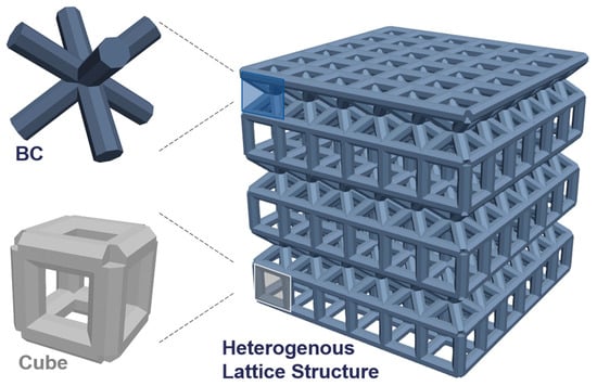
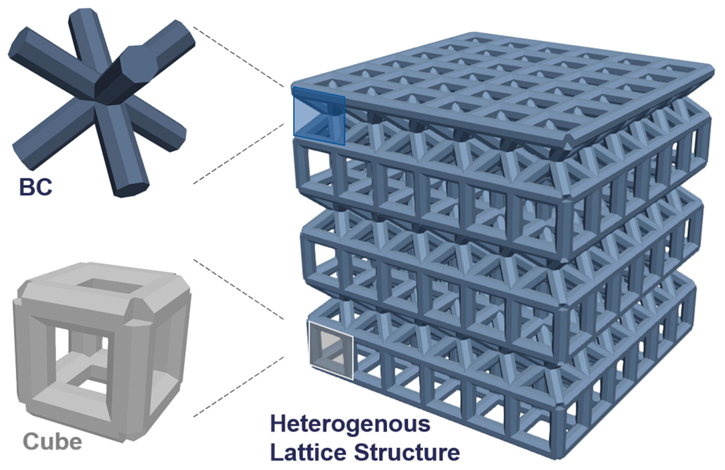
When considering the extensive design space for configuring 3D printed lattices, lattice mechanics are jointly determined by structure, process, and material [14]. Of these three considerations, mechanics influenced by structure relates to design decisions such as which unit cell topologies to include, how unit cells should be configured geometrically, and how unit cells should be spatially arranged. Each of these choices redistributes the internal load paths and reshapes the mechanical response; therefore, a lattice’s stiffness follows from its design, not its material alone [15]. Figure 1 illustrates one such variation of a heterogeneous lattice combining two types of unit cells. At a fixed porosity and beam diameter, the Cube, BC (Body-Centered) and BC–Cube cells provide different pore sizes. Mixing them builds a hierarchy of pore sizes within one lattice that mimics the distribution of pore sizes in native bone that better supports growing tissue. Smaller pores raise surface area for cell attachment and speed for early tissue filling while larger pores enable vascularization and nutrient transport tissue needs as the tissue grows [16]. These heterogeneous design strategies demonstrate the feasibility for improving bone tissue scaffolds, thereby motivating investigation into suitable materials and printing processes.
Figure 1.
Heterogeneous lattice structure with combination of BC and Cube unit cells.
Process and material decisions are tied to the 3D printer and polymer selection, where photopolymerization is a favorable process for biocompatible lattices due to its high-resolution fabrication [17,18]. Biocompatibility in the context of tissue scaffolds refers in part to its capabilities to not harm living cells, which is possible with a subset of photopolymer resins [19], while also providing mechanical integrity for prolonged use in the body. Due to the small selection of biocompatible materials for use in the body, such constraints limit variations in selected material properties; therefore, it is essential for designers to create tunable lattices to modulate mechanical properties for their end use application. Digital light processing (DLP) is a well-suited process due to its capabilities for printing biocompatible photopolymers with sub-millimeter-scale features and mechanical properties needed for creating porous tissue scaffolds [20,21]. However, there remain limitations in the process, such as variable material mechanics from post-curing times [22] and deviations from intended printing geometry [23]. As deviations concentrate at the topology transitions that define a mixed-cell lattice, the link between an intended design and its realized stiffness requires investigation for both its dimensions and mechanical properties. Dimensional properties such as porosity are measurable by weighing the fabricated lattice, while mechanical properties are measurable through destructive testing.
Since printed lattices can differ from idealized designs [24], predicting the mechanical response remains challenging. Mechanical testing of lattices is typically analyzed through stress–strain data that quantifies scalable mechanical properties [25]. Compression reflects the dominant loading of an implanted scaffold, so testing under compression helps determine lattice properties relevant for physiological loads. Lattices constructed from Cube and BC unit cells exhibit systematic differences in the Elastic Modulus, yield strength, and ultimate compressive strength as a function of relative density [26,27]. Relative density is the ratio of solid to nominal volume while porosity is the ratio of void to nominal volume. The Elastic Modulus measured for the lattice is considered an effective Elastic Modulus, determined by the lattice’s relative density and base material. The topological and mechanical differences in Cube and BC unit cells follow Maxwell’s connectivity criterion, which classifies a unit cell as stretch- or bending-dominated from its strut and node counts [2]. The Cube unit cell is stretch-dominated and carries load axially for higher stiffness, while the BC unit cell is bending-dominated and absorbs more energy per unit volume [28,29]. Incorporating two or more unit cells within a single lattice therefore opens a tunable range of properties between these extremes, governed by how the cells are mixed and arranged.
Combining different unit cells in heterogeneous lattice structures can vastly affect mechanics. In deterministic design layouts, the unit cells follow a defined pattern, such as chessboard layouts where two unit cell types alternate across adjacent positions [30,31]. Such ordered arrangements create load paths that require consideration beyond simply the proportion of unit cells present [32], because neighboring cells interact mechanically during deformation. Accordingly, changing the orientation of the same unit cell combination can alter the mechanical response even when relative density is unchanged [33]. Thus, spatial organization serves as an independent design variable that can alter lattice mechanics at a fixed porosity and unit cell composition. However, the extent to which different layouts can tune the Elastic Moduli of lattices remains an open inquiry for research, especially when considering cases relevant to personalized medicine applications with biocompatible polymer implants.
Clinically, conventional solid implants are far stiffer than the bone they replace. Titanium alloys have Elastic Moduli of 100–120 GPa, while cancellous bone is 0.02–6 GPa [34]. This mismatch often drives bone resorption, with loosening around the implant that can necessitate revision surgery. Porous polymer scaffolds are built to close this gap by lowering the Elastic Modulus toward the trabecular bone range [35,36]. However, adding porosity or thinning struts also removes load-bearing material, since stiffness and porosity are inherently coupled [37]. Spatial arrangement of the material can help tune favorable stiffness and porosity trade-offs, which is accomplished in bone through its hierarchically porous architecture [38]. The state of the art in heterogeneous lattice systems has largely focused on metallic systems [39,40], leaving comparatively little data on printed biocompatible polymer lattices [41,42]. Biocompatible photopolymers have more suitable Elastic Moduli to match bone, in the range of 50 to 250 MPa for 70% porous lattices [21]. This advantage therefore motivates research to determine their suitability for bone tissue engineering and personalized medicine applications due to their tunable mechanics.
To address the research gaps in heterogeneous lattice designs for biomedical applications, the present study investigates stochastic and deterministic design strategies characterized through manufacturing and mechanical assessments. Three homogeneous lattices are first benchmarked with 75% design porosity suitable for tissue engineering using Cube, BC, and BC–Cube unit cells. Lattices are fabricated using a biocompatible polymer with DLP printing which provides suitable microscale resolution and efficient printing speeds. The choice of printing technology constrains the range of achievable porosity for lattices, with photopolymerization being particularly well-suited for fabricating microscale pores [43]. Process parameters enable further tuning of porosity, such as UV exposure affecting the cure depth and minimum printable dimensions [23,44]. Build orientation, washing, and post-processing can also affect dimensional fidelity [45], therefore motivating the investigation of the printing process prior to mechanical testing. Lastly, variations of heterogeneous designs are tested using stochastic and deterministic layouts to determine how mechanical properties are affected by different design layouts.
The novelty of the work is the direct experimental comparison of stochastic and deterministic layouts that assess the merits of each design strategy; further novelty is achieved by using a newly characterized biocompatible polymer and design layouts with relevance to personalized medicine applications. By studying the effects of altering unit cell composition and organization as an independent variable, the study addresses key questions in the field of Design for Additive Manufacturing related to how to improve system performance for vastly complex design spaces [6]. Additionally, the study crucially grounds design decision outcomes with empirical evidence through manufacturing and mechanics assessment. Expected outcomes from the study are a quantitative link between design decisions and mechanical outcomes, thereby providing generalizable knowledge of how heterogeneous lattice design strategies can support engineering applications, with a specific focus on biomedical domains.
2. Materials and Methods
2.1. Homogeneous Lattice Design
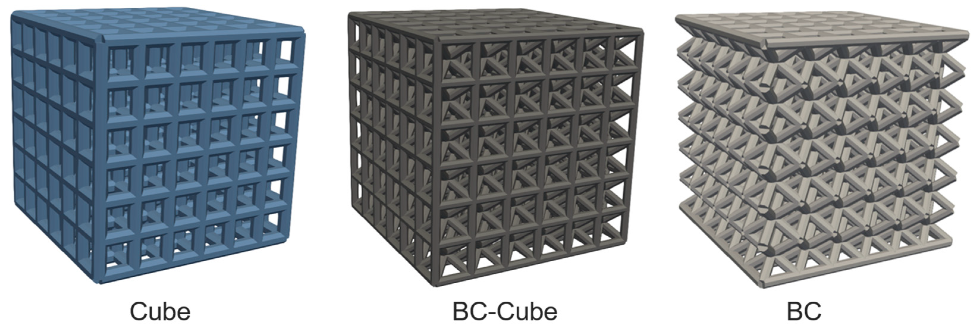
Homogeneous lattices were patterned with a single type of unit cell. Unit cell geometries were generated using a custom Python (3.11.7) and Abaqus script (Dassault Systèmes, Vélizy-Villacoublay, France) to place beam elements within a cubic volume according to specified topologies [16]. The design generation, and subsequent fabrication and testing procedures, build from past established research approaches [21,46]. Beams were placed orthogonal to one another along cubic edges to form the Cube unit cell, diagonal from one another from cubic corners connecting at the center of the cubic volume to form the BC unit cell, or a combination of both to form the BC–Cube unit cell. All unit cells had a beam diameter of 0.5 mm.
Unit cells were placed next to one another with shared beams along edges to create a cubic lattice with the same number of unit cells along each axis (Figure 2). Lattices were generated in a 6 × 6 × 6 configuration that has 216 unit cells. Lattices were generated with a porosity of 75%, where porosity is calculated as the proportion of void lattice volume to nominal lattice volume. A 75% porosity corresponds to 25% relative density. Configured lattices had their unit cell size adjusted until a desired porosity was achieved. The beam diameter was held constant at 0.5 mm during unit cell size rescaling.
Figure 2.
Homogeneous lattice designs with Cube, BC–Cube, or BC unit cells.
2.2. Stochastic Heterogeneous Lattice Design
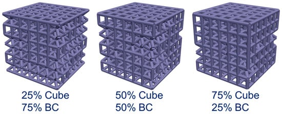
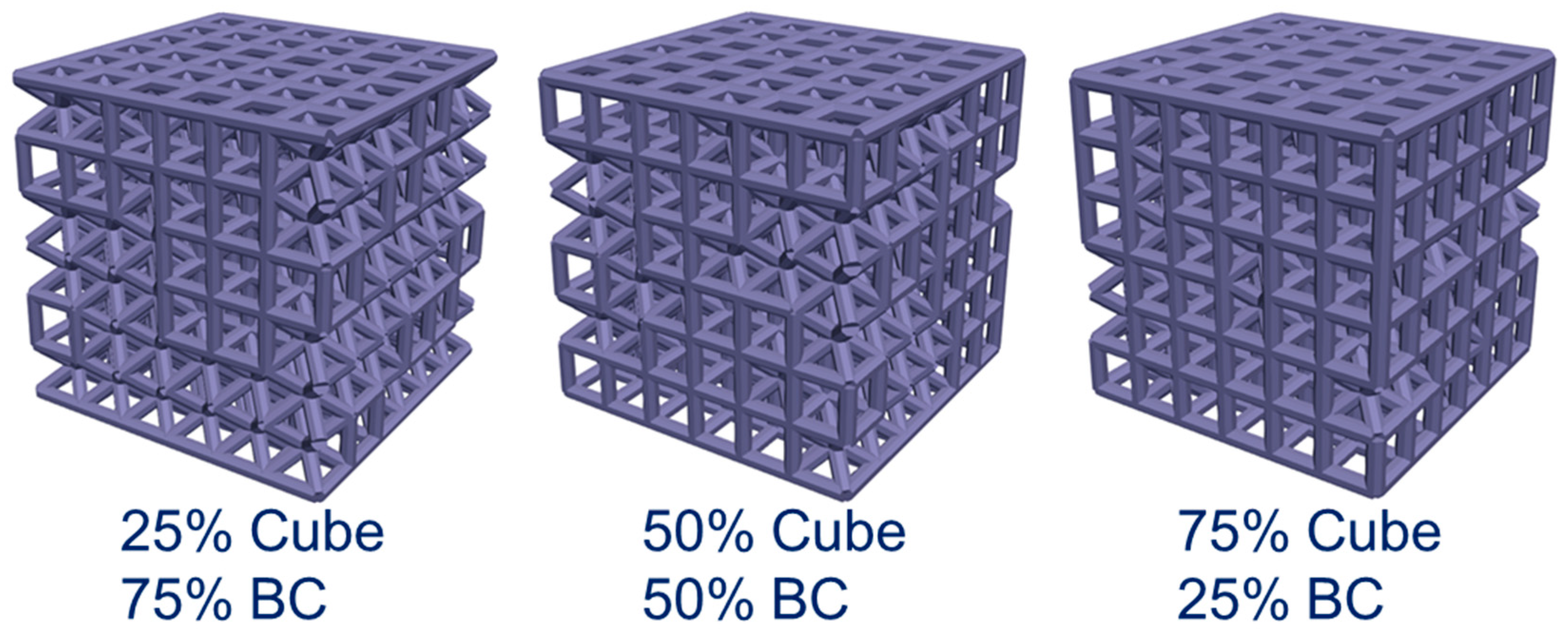
Heterogeneous lattices with stochastic patterns were generated using a python script to build a lattice by sequentially placing unit cells of Cube or BC topologies according to a random number generator with a specified chance of placing each unit cell in each location of the lattice at either 25%, 50%, or 75% probability (Figure 3). The algorithm was run multiple times until a lattice was generated with the desired proportion of unit cells that includes 25/75, 50/50, and 75/25 proportions of Cube to BC unit cells. For instance, the 25-75 stochastic lattice has 54 Cube unit cells and 162 BC unit cells that are all placed randomly. For each different proportion of unit cells, one stochastic lattice design was generated for fabrication and testing using four printed samples.
Figure 3.
Stochastic lattice designs with varied proportions of Cube and BC unit cells.
2.3. Deterministic Heterogeneous Lattice Design
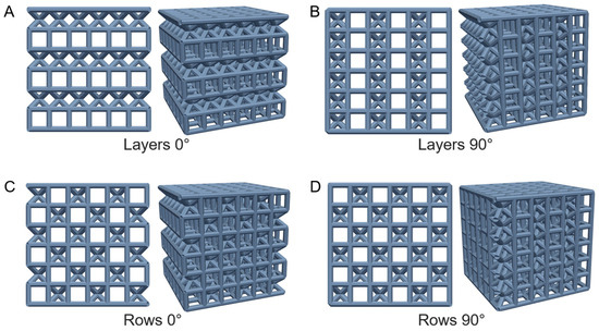
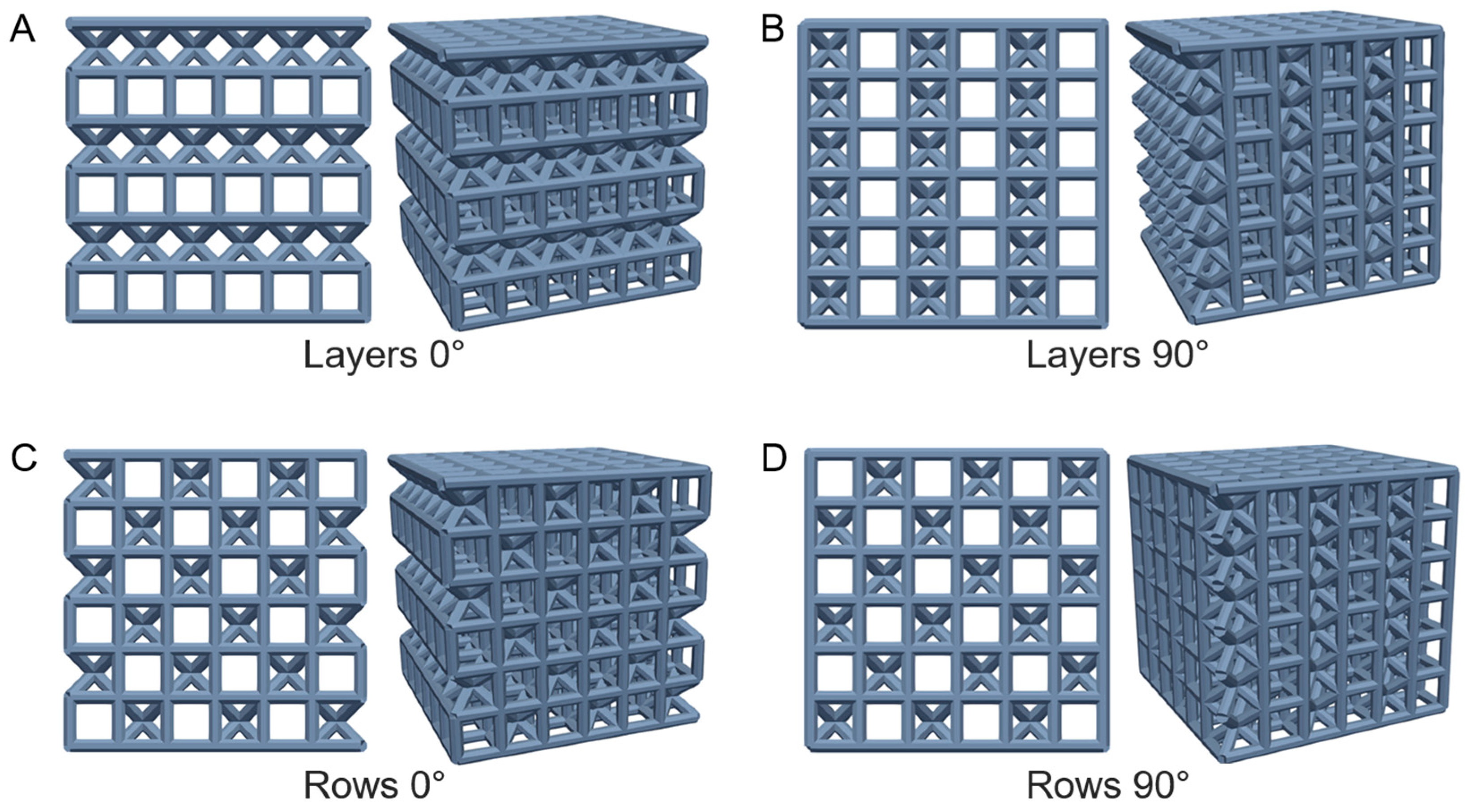
Deterministic heterogeneous layouts of Cube and BC unit cells were generated by placing each unit cell throughout a scaffold according to a specified pattern (Figure 4). The layering patterns alternate cell types within a plane, while the row patterns alternate in checkered lines throughout the lattice. Each organization type is qualified with a 0°/90° label that denotes the pattern’s orientation relative to the applied load. Layouts include Layers 0° such that horizontal planes of only Cube unit cells were alternated with horizontal planes of only BC unit cells. Layers 90° has vertical planes of only Cube unit cells alternated with vertical planes of only BC unit cells. Rows 0° placed alternating Cube and BC unit cells on one face of the lattice such that each was adjacent to a unit cell of the other type within the plane. Planes were then placed throughout the lattice mirroring this first plane, therefore forming rows of Cube and BC unit cells that extended horizontally throughout the entire lattice. The Rows 90° layout adhered to the same rules except a top plane of mixed unit cells was initially generated and rows of a single unit cell type extended vertically through the lattice.
Figure 4.
Deterministic heterogeneous lattice designs with layouts of (A) Layers 0°, (B) Layers 90°, (C) Rows 0°, and (D) Rows 90°. Note that, for each lattice, an orthographic perspective on the left shows one face of the lattice from the isometric perspective on the right. The orthographic perspective shows the side face of lattices for 0° configurations in panels (A,C) and the top face of lattices in the 90° configurations for panels (B,D).
2.4. Fabrication Process
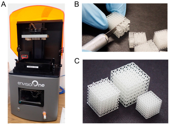
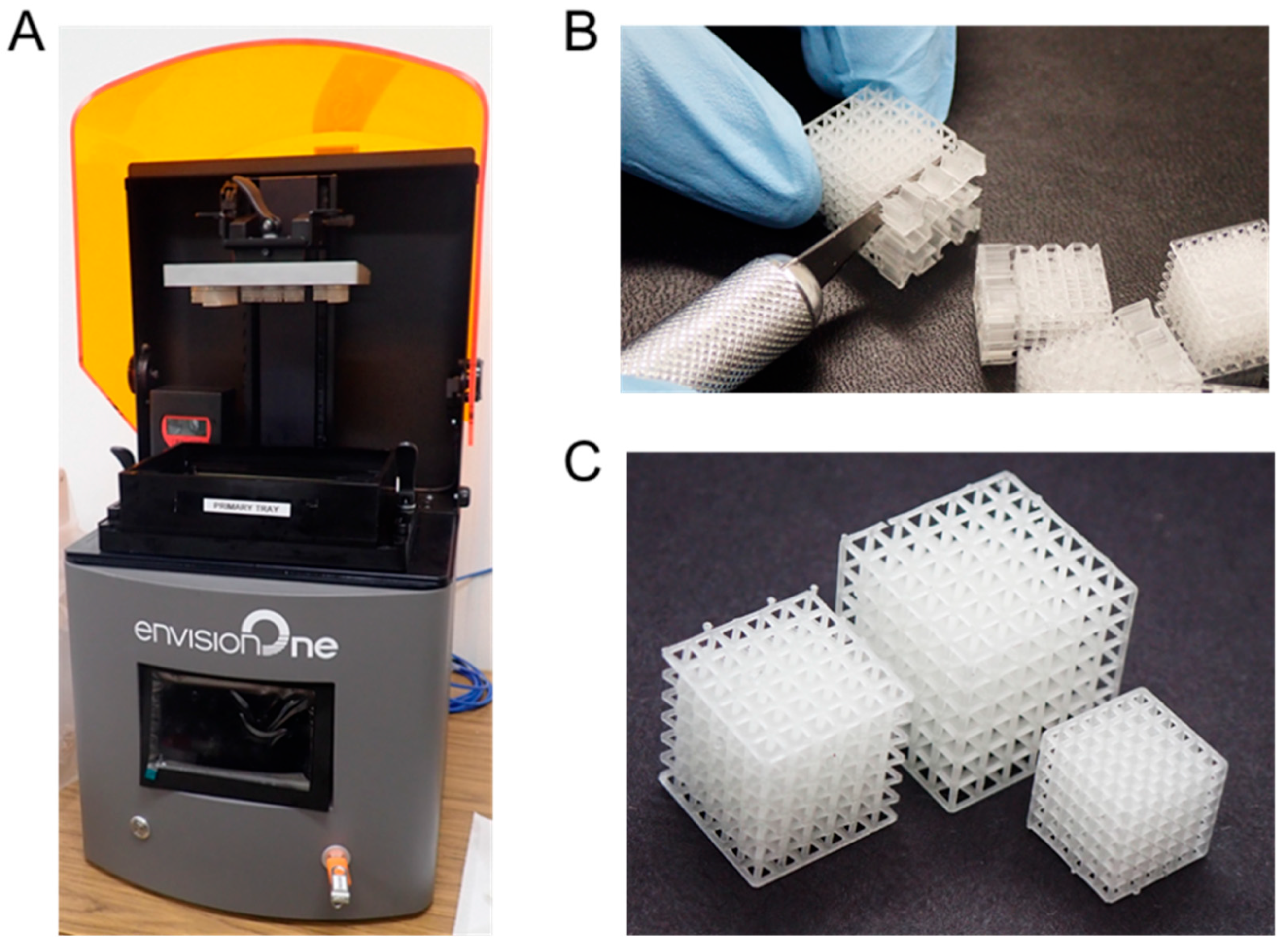
Lattices were built according to a photopolymerization 3D printing process that uses ultraviolet (UV) light to expose a two-dimensional binary pattern on a vat of resin for a specified period of time to cure each layer of material. An Envision One printer (EnvisionTEC, Dearborn, MI, USA) equipped with a 385 nm UV-LED source and native XY resolution of 93 µm was used for fabrication. The printer was selected due to its suitable resolution for printing lattices with microscale beam diameters. The wavelength of light used for printing influences the amount of energy used to cure resin during printing. The dimensions of the design are therefore tied to the exposure time and wavelength used, as longer exposure times lead to a higher proportion of resin cured, which can result in decreased porosity of prints [21].
E-Shell 600 material, which is a biocompatible acrylate/methacrylic acid-based photopolymer, was used to fabricate lattices (Figure 5A). E-Shell 600 resin is certified as Class-IIa biocompatible according to ISO 10993 [47], and is therefore used in accordance with past research supporting such materials as being relevant for 3D-printed bone scaffolds based on its mechanics and chemical composition [20,36,48]. STL files were processed in Envision One Rapid Prototype software (version-1.23.4820). Support material was generated with tapering and sized so there was enough support material to support each lattice during printing while minimizing the total amount of support material to reduce damage from support material removal.
Figure 5.
Digital light processing printer with (A) fabricated lattices on build platform, (B) support material removal, and (C) post-processed lattices.
Printing was conducted at ambient temperature. Print processing parameters were set with a layer thickness of 50 μm, upright orientation, ambient temperature, 17,500 ms burn-in time, 1000 ms waiting time before exposure, 4000 ms exposure time per layer, and 300 μm/s separation velocity. Once a layer was formed, the printer’s build platform raised and lowered to form each subsequent layer until a three-dimensional object was fabricated. Lattices were initially built on support material that adhered to the build platform for the initial layers, with the lattice structures then printed onto that support material.
After the lattices were printed, the build platform was removed. Lattices were removed from the build platform using a metal spatula and rinsed in an isopropyl alcohol bath of at least 90% concentration. Support material was removed with a blade (Figure 5B). Lattices were placed in a PCA 2000 cure chamber (EnvisionTEC, Inc., Dearborn, MI, USA) for 2 h unless otherwise specified. The chamber uses 385 nm light for deeper polymerization and 405 nm light for surface curing, with 150 W total LED power, 30 light emitters, and a 360° irradiation arrangement. Once lattices were removed from the curing chamber, rough edges were sanded down in a final post-processing step that resulted in lattices ready for mechanical testing (Figure 5C). Qualitative inspection of lattices demonstrated pores and intended topology was visible as designed throughout the lattice.
Porosity of printed lattices was determined by weighing lattice samples and comparing their weight to the weight of a solid with the same nominal volume of the same material [21]. After fabrication and post-processing, samples were weighed to determine mass M for each lattice. Next the lattice length L, width W, and height H were measured with calipers. Lattice porosity P was then calculated as
with the base material density ρm provided as 1.19 g/cm3 [49]. The porosity defines the ratio of void material to overall volume of the lattice, which is a key metric related to mechanical and biological functionality. A higher porosity means there is a greater proportion of void space for for cell growth and nutrient transport, while a lower porosity means there is a greater proportion of solid material that provides further mechanical stiffness and strength.
2.5. Print Validation
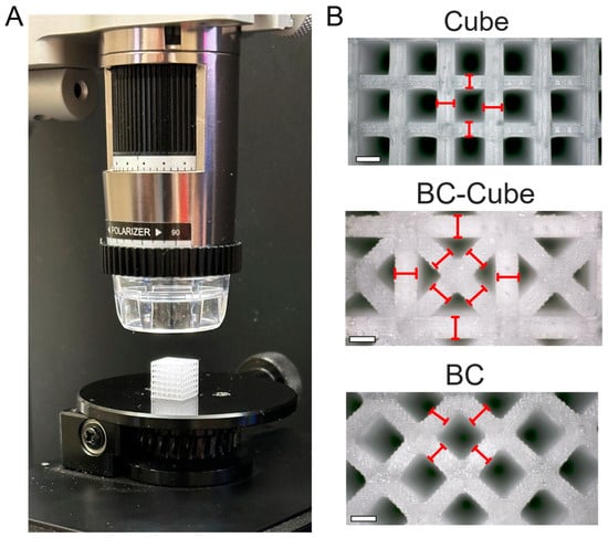
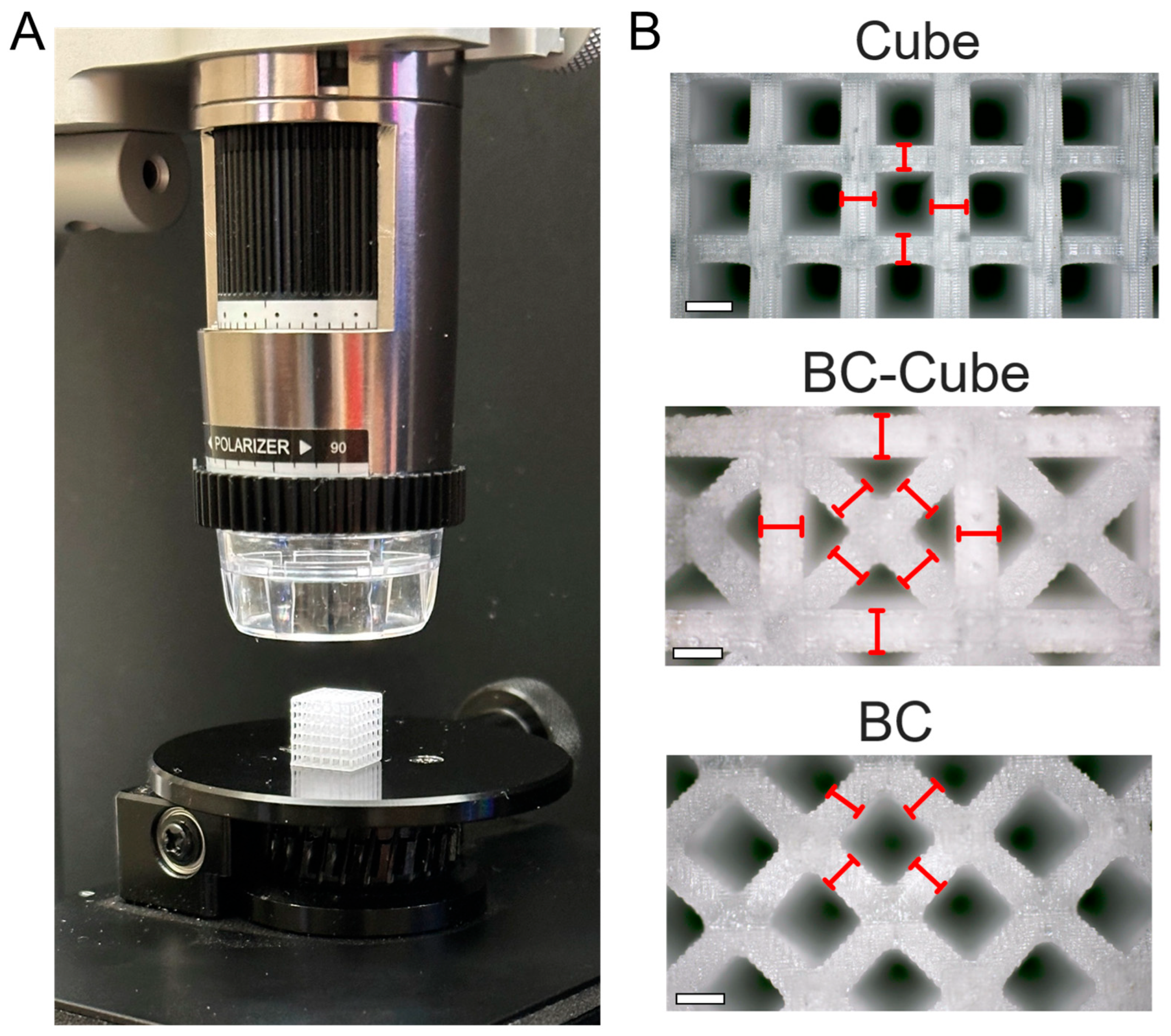
Beam diameters of the printed lattices were verified by reflected-light optical microscopy using a Dino-Lite AM8917MZT digital microscope (AnMo Electronics Corp, New Taipai City, Taiwan; 8 MP, 3840 × 2160 pixels, 10–220× magnification) with DinoCapture 2.0 software. It was set up with automatic magnification reading and each specimen was mounted on a rotary stage above a micrometer-driven translation stage (Figure 6). Beams were imaged on the side outer faces of each specimen at a location towards the center of the lattice. Diameters were measured perpendicular to the beam axis at the beam mid-span. Equal sampling was conducted for beams in each orientation, with sixteen measurements collected per design. Results demonstrated a high agreement with printed lattice mean beam diameter compared to the designed 0.5 mm diameter. The average beam diameter of the Cube, BC–Cube, and BC designs were 0.506 ± 0.010, 0.508 ± 0.004, and 0.501 ± 0.002 with standard deviations of 0.039, 0.008, and 0.015, respectively.
Figure 6.
Print validation with (A) optical microscopy setup used for beam diameter verification and (B) measurements demonstrated for beams of each lattice type. Scale bars represent 0.5 mm.
2.6. Mechanical Testing
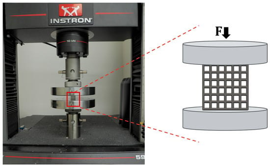
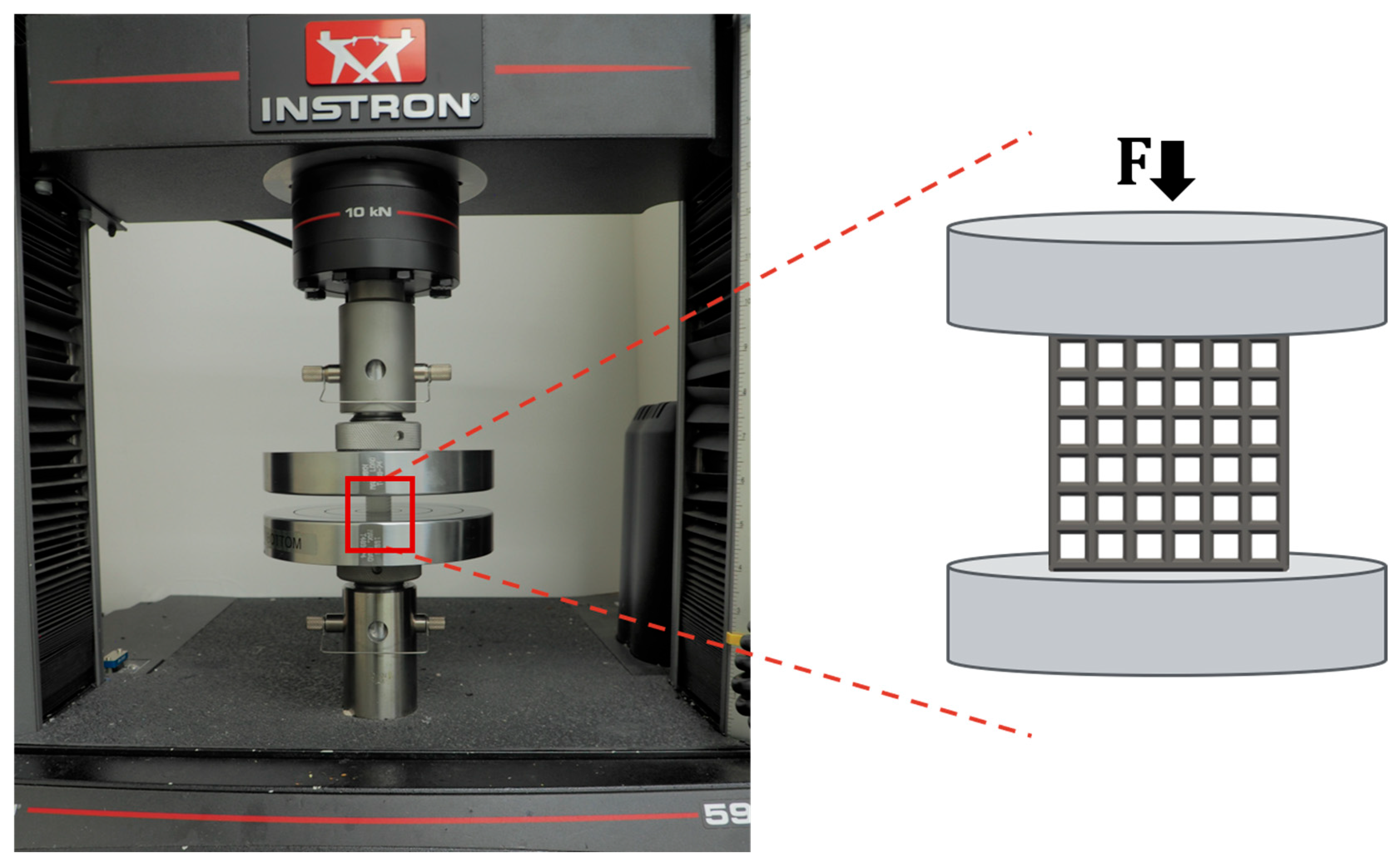
Uniaxial compression testing was performed on an Instron 5966 universal testing system (Instron, Norwood, MA, USA) with a 10 kN load cell capacity operating under displacement control, with consistent protocols for polymer lattice testing research to determine Elastic Modulus measurements [48] (Figure 7). Testing was conducted under quasi-static conditions at a loading rate of 0.1 strain per minute, which facilitates calculation of the Elastic Modulus, yield stress, and ultimate stress with a Python script. For BC unit cells on the top and bottom planes of homogeneous and heterogeneous lattices, orthogonal beams were added on planes that contacted compression plates during mechanical testing to facilitate more consistent contact between the lattice and compression plates, which is incorporated into the original CAD design and then 3D printed. These added beams ensure that boundary conditions are standardized for all lattices by providing a consistent contact geometry between all tested lattice samples and the compression plates.
Figure 7.
Lattice in mechanical testing machine with schematic demonstrating compressive lattice loading.
Engineering compressive stress σ and strain ε were computed from the recorded force F and displacement δ following equations with A0 as the nominal cross-sectional footprint area of the lattice perpendicular to the loading direction; H0 is the initial lattice height. The Elastic Modulus E was determined from selecting two stress and strain values in the linear elastic region of the resulting stress–strain response as
to determine mechanical properties of lattices. The linear elastic region occurs when the stress–strain curve response has a constant slope after an initial toe region and prior to yielding. The yield stress was determined using the 0.2% offset method, where a line parallel to the linear elastic region is shifted by 0.002 strain with yield determined when it intersects with the experimental data. Ultimate strength is reported as the highest compressive stress measured for each sample during testing.
At least four samples, all fabricated from the same print batch, were tested for each lattice design, with mechanical property results reported as mean ± standard error of the mean. The sample size was determined to ensure consistency with standards in the field for testing at least three samples [50,51], which enables statistical determination of differences in designs according to the mechanical properties of interest. If further statistical power is needed a larger sample size can be used; however, for the designs and printing parameters used, consistent behavior among samples is expected for these mechanical systems. Samples were tested between one day and one week after printing, unless otherwise specified, to limit the influence of post-build storage on measured stiffness.
2.7. Statistical Analysis
All statistical analyses were performed using GraphPad Prism (version 11.0.2). Four independent specimens were tested for each experimental condition, and the results are presented as mean ± standard error of the mean. Comparisons involving more than two independent groups were performed using ordinary one-way analysis of variance (ANOVA) followed by Tukey’s multiple-comparisons test for all pairwise comparisons of group means. Comparisons between two independent groups were performed using two-tailed unpaired t-tests. A p-value < 0.05 was used to determine statistical significance.
3. Results and Discussion
3.1. Manufacturing Process
Initially, the influence of the manufacturing process parameters on mechanics was investigated using a BC–Cube unit cell as a datum point. The BC–Cube unit cell was used to configure control lattices that were designed with the same 3 × 3 × 3 configuration as past studies to facilitate controlled comparisons [48]; therefore, it supports an investigation into material and process variations rather than investigations into how the design of the lattice itself affects mechanical outcomes. The unit cells had beam diameters of 0.8 mm with 50% porosity. These printed control lattices had measured porosities of 53% ± 0.3%. The results of mechanical testing for the Elastic Modulus for varied UV post-curing times are provided in Table 1.
Table 1.
Measured E for BC–Cube samples with varied UV curing time. Values are presented as mean ± SEM (n = 4). Different lowercase superscript letters indicate significant differences among curing times (p < 0.05).
Results show that the Elastic Modulus increased with longer UV curing times. There was a large initial difference from 0 to 4 min of 45.9 MPa to 193 MPa that further increased until reaching a value of about 350 MPa for samples cured for 60 min or longer. No significant differences were observed among the 60, 120, and 240 min groups, indicating diminishing mechanical benefits from additional post-curing beyond 60 min under the conditions investigated. The PCA 2000 used for post-print curing employs nominal 385 and 405 nm UV-LED sources. The effectiveness of these wavelengths depends on their overlap with the absorption characteristics of the resin’s photo initiator system [22]. Under consistent chamber conditions, increasing the post-curing duration increases the total radiant exposure. Longer post-curing has similarly been shown to increase the degree of conversion and microhardness of 3D printed resins [52]. This mechanism is consistent with the increase in the Elastic Modulus from 45.9 MPa without post-curing to approximately 350 MPa after 60 min.
A one-way ANOVA confirmed that UV curing time significantly affected the Elastic Modulus (F(7,24) = 233.7, p < 0.0001). Tukey’s post hoc test (HSD = 32.7 MPa) resolved four significance groups (Table 1). The Elastic Modulus increased sharply from 45.9 ± 1.8 MPa with no post-curing time to 193.0 ± 7.8 MPa after 4 min (p < 0.0001), while 4 and 8 min were statistically indistinguishable (p = 0.96). Values plateaued near 350 MPa for curing times greater than 60 min, with 60, 120, and 240 min forming one group (p > 0.99). Curing durations beyond 60 min produced no further significant increase in Elastic Modulus measurements.
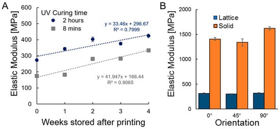
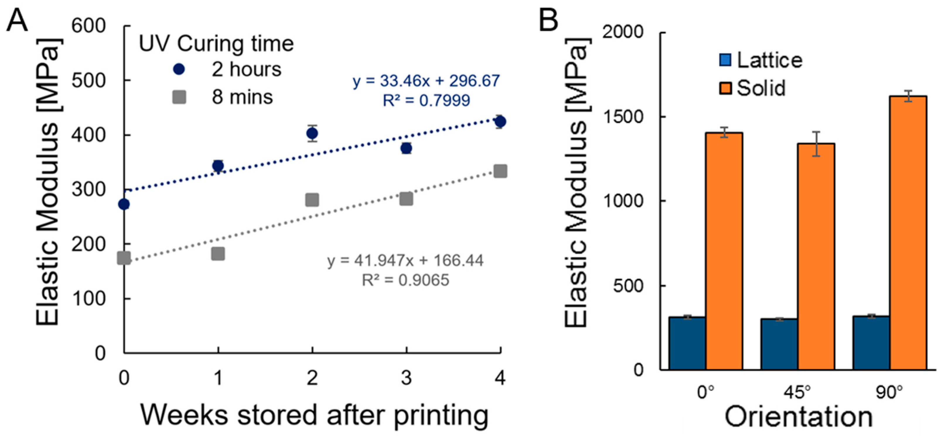
Lattices were cured in the UV curing chamber for 8 min, following the manufacturer’s recommendation. After preliminary testing, the experiment also included a set of samples cured for 2 h in the UV curing chamber. Both sets of samples were then stored for up to 4 weeks after printing and tested to determine the influence of these conditions on mechanical properties. During storage, samples were stored in closed containers in the dark at ambient temperature, which is consistent with standard storage protocols [53]. The influence of storage time on the Elastic Modulus was investigated, testing the lattices 0, 1, 2, and 4 weeks after the printing date (Figure 8A).
Figure 8.
Mechanical testing results for (A) lattices with varied UV curing time and (B) lattice and solid structures of different printing orientations. Equations provided indicate the lines of best fit included for panel A.
The Elastic Modulus was significantly higher for lattices cured for 2 h in comparison to 8 min for all storage durations, with about a 100 MPa difference at 0 weeks that narrowed to about 70 MPa after 4 weeks. The increase in the Elastic Modulus with storage time may result from continued cross-linking of the printed polymer [48]. Lattices had higher Elastic Moduli after being stored for a greater number of weeks with strong fittings to linear models. The 2 h curing time linear fit (y = 33x + 297) had an R2 = 0.8 while the 8 min curing time linear fit (y = 42x + 166) had a better linear fit with R2 = 0.9. The overall increases in Elastic Moduli with storage time may result from continued cross-linking of the printed polymer. The data suggests that storage time should be tracked when testing the mechanical properties of 3D printed lattices to achieve consistent and comparable results. Therefore, all further testing was conducted with lattices tested within 2 to 7 days of printing.
Solid cubes of side lengths of 6 mm and BC–Cube lattices were tested to measure any anisotropy in mechanical properties. Samples were printed as demonstrated in Figure 5 or with a 45° rotation along all axes. Mechanical tests were then conducted with 0°, 45°, and 90° orientations. The 90° orientation and 0° orientation were printed in the same manner, but the 90° samples were rotated such that their build layers were oriented perpendicular to the applied testing load. Results demonstrate that the 90° solid with about a 1620 MPa Elastic Modulus is significantly higher than the 0° and 45° solid orientations with about a 1400 MPa Elastic Modulus (Figure 8B). For lattice samples that all had Elastic Moduli from about 300 MPa to 320 MPa, there was no significant difference based on orientation. These results suggest that print orientation anisotropy accounts for less than 15% of mechanical stiffness differences in samples, while for lattices with diagonal elements there is minimal measured anisotropy. Therefore, any larger differences in mechanics between designs are attributable to their design differences, rather than any influence of material or processing effects between samples.
3.2. Homogeneous Lattice Mechanics
Homogeneous lattices were constructed from Cube, BC–Cube, and BC topologies in 6 × 6 × 6 configurations with 75% designed porosity. Lattices were mechanically tested with design configurations and measurements are provided in Table 2.
Table 2.
Design and measurements for homogeneous unit cell lattices.
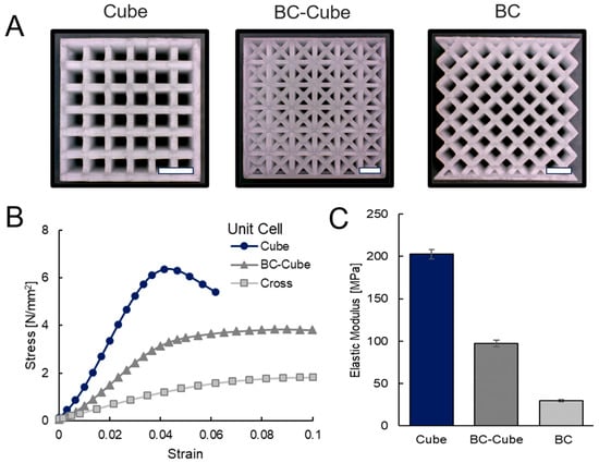
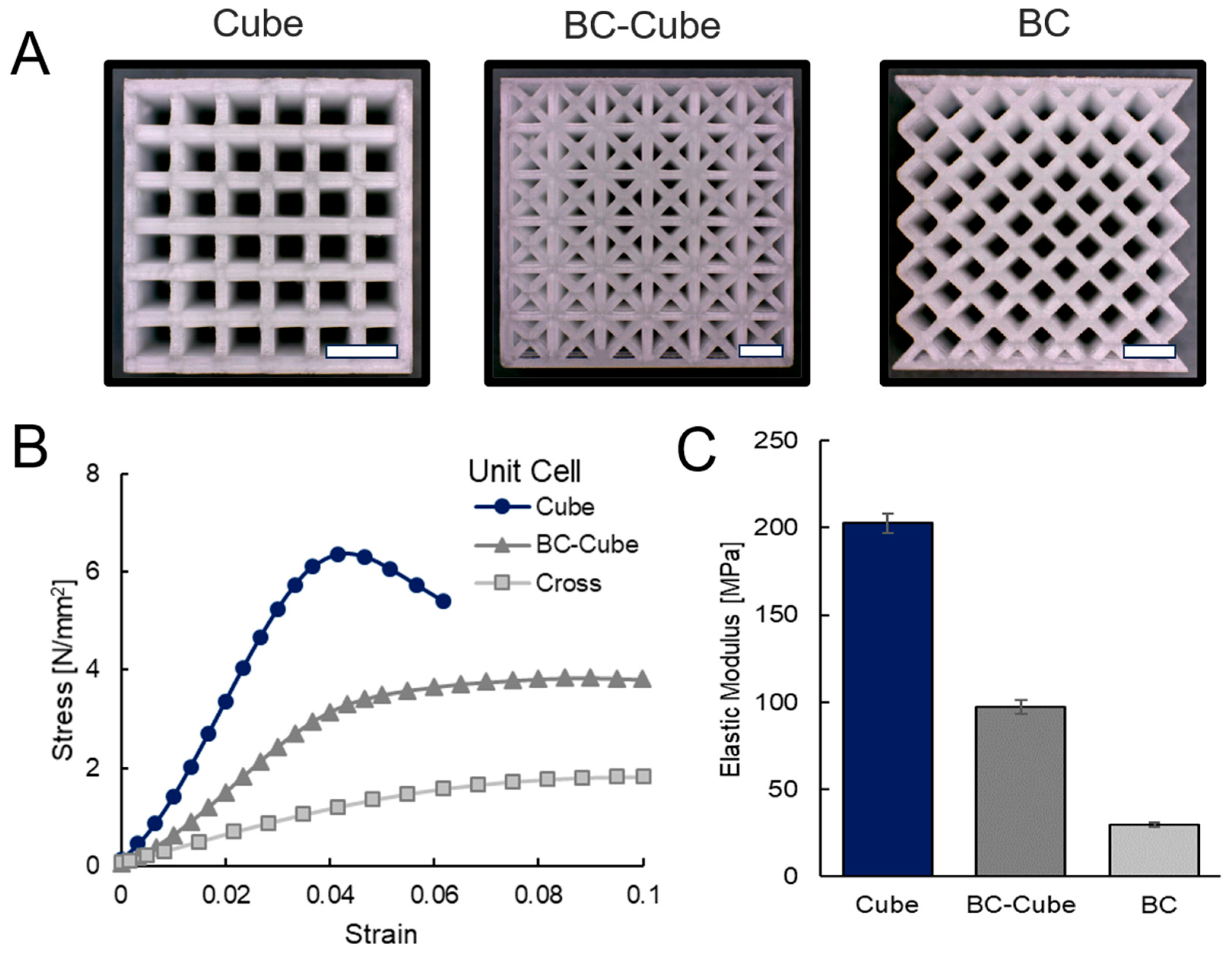
All designs achieved a measured porosity of about 75%. Yield strain was similar for all lattices at 0.04, although yield stress, Elastic Modulus, and ultimate strength were highest for the Cube, then BC–Cube, and lowest for the BC lattice. These trends correspond with whether beams are aligned proportionally with the applied load for each unit cell. Prints and further data trends are provided in Figure 9.
Figure 9.
Homogeneous lattice structures (A) printed with (B) stress–strain curves and (C) measured Elastic Moduli. Scale bars represent 2 mm.
The printing results demonstrate each design was fabricated qualitatively as expected, with scaling according to unit cell size while retaining a constant beam diameter across all designs (Figure 9A). When considering the stress–strain data in Figure 9B, all designs yielded about 0.04 strain, but the Cube design had a drop in stress shortly after yielding, consistent with abrupt collapse of its stretch-dominated struts and layer failures (Figure 9B) [15]. Results show that the Cube design achieves a significantly (p ≤ 0.001) higher Elastic Modulus (202 MPa) than the BC–Cube design (97 MPa) which in turn has a significantly higher Elastic Modulus (p ≤ 0.001) than the BC design (30 MPa) (Figure 9C). The trends highlight that different unit cells provide different mechanical properties for lattices and when more beams are aligned with the loading direction, the mechanical properties increase. Computational studies and experiments of Cube unit cells with higher stiffness than BC unit cells highlights the primary stresses carried are in the beams aligned with the loading direction [21,54]. Greater stiffness is achieved when such beams are proportionally elongated in comparison to beams transverse to the loading direction.
3.3. Stochastic Lattice Mechanics
Stochastic heterogeneous lattices were constructed by specifying the proportion of Cube and BC unit cells in 6 × 6 × 6 lattices and adding them randomly until the specified distribution was achieved. Stochastic lattices were designed according to the specifications in Table 3 with subsequent mechanical measurements included.
Table 3.
Design and measurements for heterogeneous lattices with stochastic unit cell mixtures.
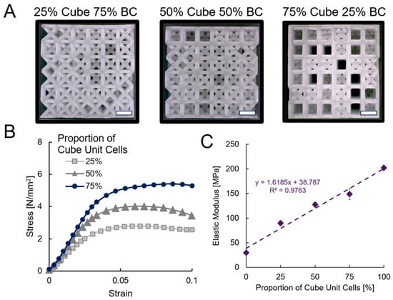
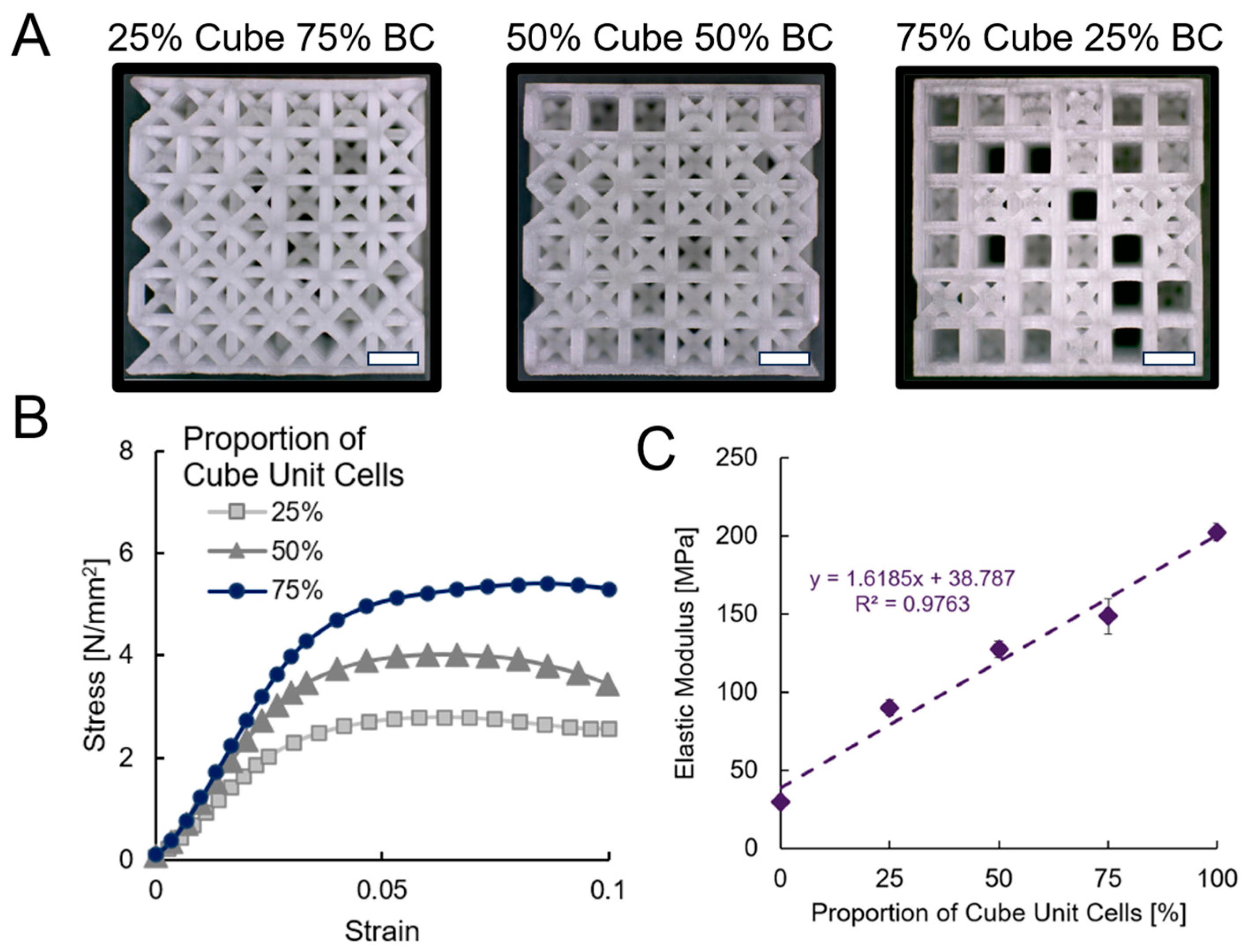
All topologies had porosity from 73% to 75% on average with yield strain of about 0.03. Yield stress, Elastic Modulus, and ultimate strength increased as a greater proportion of Cube unit cells were added. The printing of the lattices in addition to stress–strain response and Elastic Moduli comparisons are provided in Figure 10.
Figure 10.
Stochastic heterogeneous lattice structures (A) printed with (B) stress–strain curves and (C) measured Elastic Moduli. Scale bars represent 2 mm.
The printing results demonstrate each design was fabricated qualitatively as expected with randomly distributed unit cells throughout each lattice (Figure 10A). Stress–strain curves demonstrated an initial linear elastic region until yielding near 0.03 strain, with minimal change in stress after yielding up to 0.1 strain (Figure 10B). When the Elastic Modulus is plotted according to the proportion of Cube unit cells in each structure and compared with homogeneous Cube and BC lattices from Figure 9, a linear relationship according to a rule-of-mixtures emerges with the Elastic Modulus increasing with higher proportions of Cube unit cells (Figure 10C). The linear fit for the curve is E = 1.61x + 38.8 with R2 = 0.98, where x refers to the proportion of Cube unit cells. Thus, changing the percentage of each unit cell type allows tuning the Elastic Modulus without modifying the lattice’s porosity while combining geometric attributes of each unit cell.
When interpolating from the values of the homogeneous endpoints to predict the properties of stochastic heterogeneous Elastic Moduli there is also strong agreement in the data supporting a rule-of-mixtures relationship. Based on interpolated values, it is expected stochastic heterogeneous lattices would have Elastic Moduli of 73.0, 116.0, and 159.0 MPa for 25%, 50%, and 75% proportions of Cube unit cells, respectively. The measured experimental values are within 10.3 to 17.4 MPa of these calculated values, which demonstrates the interpolation method assuming a proportional increase through interpolation with validated homogeneous measurements also agrees closely with a rule-of-mixtures interpretation. Deviances from the ideal rule-of-mixtures interpretation can be attributed to manufacturing inconsistencies or possible variation in how different stochastic heterogeneous lattices may behave due to random chance in how unit cells are organized.
From a mechanics perspective, the approximately linear trend can be interpreted as a first order consequence of progressively replacing the more compliant, bending-dominated BC topology with the stiffer, stretch-dominated Cube topology. Increasing the Cube cell proportion also increases the contribution of struts aligned with the loading direction in a predictable manner. Previous numerical work similarly showed that introducing a stiffer, stretch-dominated unit cell into a bending-dominated lattice increases Young’s modulus, although the number and spatial pattern of the stiffer cells also influence the response [11,12]. Further, because the different unit cells are randomly organized throughout the lattice, they do not gain a strategic benefit in a directed modulation of stress throughout the lattice, thereby suggesting the overall response is dictated by the strict sum of the proportional unit cell contributions.
3.4. Heterogeneous Lattice Mechanics
The designed heterogeneous lattices with organized layouts were printed and measured according to the designs in Table 4, which includes subsequent porosity and mechanical property measurements.
Table 4.
Design and measurements for heterogeneous lattices of varied unit cell organizations.
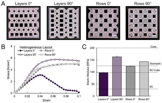
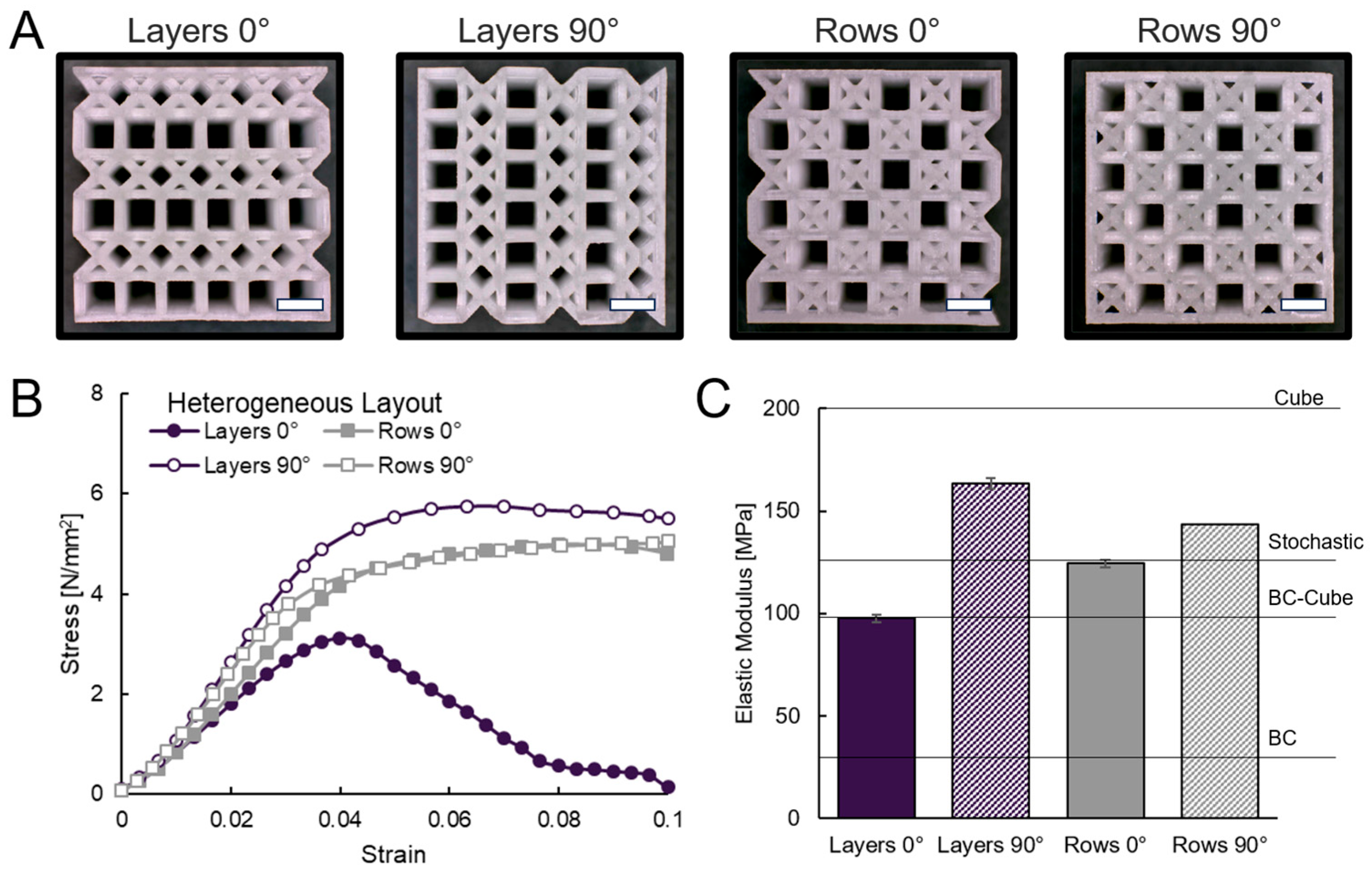
The porosity of the lattices ranged from 72% to 74% with yield strains of 0.03 to 0.04. Yield stress, the Elastic Modulus, and ultimate strength were lowest for the Layers 0° layout and highest for the Layers 90° layout followed by the Rows 90° layout. Printed designs with subsequent experimental analyses and comparison of stress–strain and Elastic Modulus data are provided in Figure 11.
Figure 11.
Deterministic heterogeneous lattice designs (A) printed with (B) stress–strain curves and (C) measured Elastic Moduli. Scale bars represent 2 mm.
The printing results demonstrate that each design was fabricated qualitatively as expected with deterministic heterogeneous layouts and visible pores (Figure 11A). When considering the stress–strain curves, the Layers 0° layout had a drop in stress after reaching yielding, whereas the remaining layouts did not (Figure 11B), which is potentially due to weaknesses perpendicular to the load direction due to having a single type of unit cell within a given horizontal plane. The Layers 0° layout also has the lowest Elastic Modulus of all heterogeneous designs, which is about the same as the homogeneous BC–Cube lattice with 97 MPa. These results demonstrate that heterogeneously mixing unit cells, rather than combining Cube or BC to homogeneously create BC–Cube unit cells, results in equal or higher Elastic Modulus measurements at comparable porosity.
Compared to the stochastic layouts with 50% of each unit cell type, the Rows 0° layout has an Elastic Modulus of 124 MPa, which is similar to the stochastic layouts, while Rows 90° has a higher Elastic Modulus of 143 MPa and the Layers 90° layout increases further to 163 MPa. Because the Layers 0° and Layers 90° layouts share the same composition and porosity and differ only in orientation relative to loading, their 1.7-times difference in the Elastic Modulus (97.6 versus 163.4 MPa) isolates a controllable anisotropy set by arrangement alone. Both row designs showed a similar directional effect at a smaller magnitude (124.4 versus 143.3 MPa).
This directional tunability further mimics the load-aligned stiffness of trabecular bone that can promote mechanical and biological functionality [21]. The orientation-dependent stiffness differences are consistent with redistribution of the internal load paths as the Cube and BC cells are reorganized relative to the compression direction. Under this interpretation, the vertical Cube planes or rows in the Layers 90° and Rows 90° layouts provide more continuous stiff paths along the loading direction, whereas the transverse arrangement in Layers 0° requires greater deformation of the more compliant BC layers. The interpretation agrees with recent assessments of different types of heterogeneous lattices using finite element analysis and mechanical testing that demonstrated stress distributions [27]. In these studies, designs with higher Elastic Moduli relied on more consistent organization of their unit cells to effectively distribute stress throughout the lattice. These results demonstrate that mixing unit cell types affects the mechanical response of 3D printed lattices. Both the percentage of each type of unit cell and the manner they are organized within the lattice can provide routes for tuning yield stress and the Elastic Modulus.
3.5. Limitations and Future Work
The study investigated design decisions through controlled comparisons of lattices; however, it is not possible to control all decision variables simultaneously due to dependencies. For instance, beam diameter and unit cell size cannot possibly be held constant across topologies at a fixed porosity. In this study, beam diameter and porosity were fixed, so unit cell size necessarily varied (1.38–2.30 mm) as a non-fixed variable. However, due to the scaling effects of mechanical properties in metamaterials, unit cell size changes are not expected to have a significant influence on mechanical outcomes if a suitable number of unit cells are included, which is addressed by the 6 × 6 × 6 configuration of the lattices. Further, there are inherent variations in printed lattice porosity measurements due to the stochastic nature of additive manufacturing. However, the variation in average porosity for the designed samples (Table 2, Table 3 and Table 4) is less than 3%, which cannot account for the wide range of observed mechanical properties across all samples from 30 MPa to 200 MPa for the homogeneous designs. For instance, in a previous empirical study relating variation in porosity to mean mechanical properties [55], a 3% change in porosity accounts for less than a 5% change in the Elastic Modulus for BC–Cube lattices with 0.5 mm beam diameters and 50% designed porosity.
When considering stochastic arrangements of unit cells only, finite subsets are possible to build and test, in comparison to the high number of permutations of different unit cells throughout the lattice. However, the highly linear trend in the data correlating unit cell proportion to mechanical properties, in comparison to the deviances from a rule-of-mixtures for the deterministic layouts, suggests the stochastic arrangements are representative of a consistent universal trend. For each Cube-to-BC proportion, only one stochastic unit cell arrangement was generated, although four separately printed specimens of that arrangement were tested. The measured variation therefore reflects fabrication and mechanical testing variability but does not capture configurational variability among independently generated stochastic layouts. Although the three tested configurations exhibited an approximately linear Elastic Modulus to composition relationship, this trend cannot establish that every random realization at the same composition would produce an equivalent response. However, since three independent testing points that were arbitrarily selected contributed to a strong linear relationship, it is suggestive that other arbitrarily chosen stochastic configurations would also follow such trends. In related studies, randomly generated lattices followed similar behavior and heuristic algorithms required consideration of thousands of designs to significantly improve performance beyond the properties of arbitrarily configured heterogeneous lattices [27]. Future work should test multiple independently generated layouts at each composition to quantify variability and determine the statistical robustness of the observed relationship.
These findings provide the foundations for many directions of future work in mixed unit lattice design and testing. Mechanical testing was conducted for uniaxial compression, but shear, tensile, and multiaxial loading could provide further insights into trade-offs in behavior, especially as the BC cell is expected to perform much better in shear conditions than the Cube cell. Finite-element analysis of failure behavior and micro-computed tomography to quantify internal strut geometry, surface roughness, and printing defects could also provide further insights in linking manufacturability to performance for these designs. Additionally, the use of computational design algorithms could provide a further means of exploring the design space and finding favorable layouts for mixed unit cell systems beyond the four layouts tested.
4. Conclusions
This study investigated the spatial arrangement of mixed unit cells as a design strategy for altering mechanical properties while retaining a constant porosity, which is essential for biomedical applications such as bone tissue engineering. Lattices were designed and manufactured using DLP printing with a biocompatible polymer. At a fixed 75% porosity, homogeneous lattices had Elastic Moduli spanning 30–202 MPa. Stochastic mixing of Cube and BC unit cells followed a rule-of-mixtures within this range (R2 = 0.98). However, deterministic design of mixed unit cell layouts bypassed these constraints. For instance, the Layers 90° configuration reached 163.4 MPa, which is a 29% increase in comparison to the stochastic mixture with a similar distribution of unit cells. These results highlight how the spatial arrangement of unit cells enables tuning of mechanical properties that are useful for tailoring according to application needs, such as patient-specific tissue scaffolds. When tuning patient-specific scaffolds, the design strategy provides the opportunity to alter unit cell organization to reach a desired Elastic Modulus, thereby retaining overall porosity and pore size distribution at a specified value. Overall, these findings open doors to further studies in design where the deterministic configuration of heterogeneous lattices can provide specified properties for diverse engineering applications.
Author Contributions
Conceptualization, G.B. and P.F.E.; methodology, G.B. and P.F.E.; software, G.B. and P.F.E.; validation, A.K.M.A.H., G.B. and P.F.E.; formal analysis, G.B. and P.F.E.; investigation, G.B. and P.F.E.; resources, P.F.E.; data curation, P.F.E.; writing—original draft preparation, A.K.M.A.H., G.B. and P.F.E.; writing—review and editing, A.K.M.A.H. and P.F.E.; visualization, A.K.M.A.H., G.B. and P.F.E.; supervision, P.F.E.; project administration, P.F.E.; funding acquisition, P.F.E. All authors have read and agreed to the published version of the manuscript.
Funding
This research received no external funding.
Data Availability Statement
The raw data supporting the conclusions of this article will be made available by the authors on request.
Acknowledgments
An early iteration of this work was published as conference proceedings and presented at the ASME International Design Engineering and Technical Conference [46].
Conflicts of Interest
The authors declare no conflicts of interest.
References
- Wu, W.; Xia, R.; Qian, G.; Liu, Z.; Razavi, N.; Berto, F.; Gao, H. Mechanostructures: Rational mechanical design, fabrication, performance evaluation, and industrial application of advanced structures. Prog. Mater. Sci. 2023, 131, 101021. [Google Scholar] [CrossRef] [Scilit]
- Ma, W.W.S.; Yang, H.; Zhao, Y.; Li, X.; Ding, J.; Qu, S.; Liu, Q.; Hu, Z.; Li, R.; Tao, Q.; et al. Multi-Physical Lattice Metamaterials Enabled by Additive Manufacturing: Design Principles, Interaction Mechanisms, and Multifunctional Applications. Adv. Sci. 2025, 12, 2405835. [Google Scholar] [CrossRef] [Scilit] [PubMed]
- Namvar, A.; Lozanovski, B.; Downing, D.; Williamson, T.; Kastrati, E.; Shidid, D.; Hill, D.; Buehner, U.; Ryan, S.; Choong, P.F.; et al. Finite element analysis of patient-specific additive-manufactured implants. Front. Bioeng. Biotechnol. 2024, 12, 1386816. [Google Scholar] [CrossRef] [Scilit] [PubMed]
- Gandhi, R.; Salmi, M.; Roy, B.; Pagliari, L.; Concli, F. Mechanical performance, fatigue behaviour, and biointegration of additively manufactured architected lattices. Virtual Phys. Prototyp. 2025, 20, e2530733. [Google Scholar] [CrossRef] [Scilit]
- Olivas-Alanis, L.H.; Fraga-Martínez, A.A.; García-López, E.; Lopez-Botello, O.; Vazquez-Lepe, E.; Cuan-Urquizo, E.; Rodriguez, C.A. Mechanical Properties of AISI 316L Lattice Structures via Laser Powder Bed Fusion as a Function of Unit Cell Features. Materials 2023, 16, 1025. [Google Scholar] [CrossRef] [Scilit] [PubMed]
- Egan, P.F. Design for Additive Manufacturing: Recent Innovations and Future Directions. Designs 2023, 7, 83. [Google Scholar] [CrossRef] [Scilit]
- Zadpoor, A.A. Mechanical performance of additively manufactured meta-biomaterials. Acta Biomater. 2019, 85, 41–59. [Google Scholar] [CrossRef] [Scilit] [PubMed]
- Bittner-Frank, M.; Reisinger, A.G.; Andriotis, O.G.; Pahr, D.H.; Thurner, P.J. Cortical and trabecular mechanical properties in the femoral neck vary differently with changes in bone mineral density. JBMR Plus 2024, 8, ziae049. [Google Scholar] [CrossRef] [Scilit] [PubMed]
- Beisekenov, N.; Sadenova, M.; Azamatov, B.; Syrnev, B. Analysis of Biomechanical Characteristics of Bone Tissues Using a Bayesian Neural Network: A Narrative Review. J. Funct. Biomater. 2025, 16, 168. [Google Scholar] [CrossRef] [Scilit] [PubMed]
- Zhang, M.; Gao, K.; Liu, J.; Zou, Z.; Yang, J.; Qian, M.; Zhai, W.; Wu, Z. Breaking Stiffness-Tunability Trade-offs in Metamaterials: A Minimal Surface Guided Hybrid Lattice Strategy. Adv. Sci. 2025, 12, e10586. [Google Scholar] [CrossRef] [Scilit] [PubMed]
- Yu, G.; Miao, C.; Wu, H.; Liang, J. Mechanical performance of heterogeneous lattice structure. Vibroeng. Procedia 2023, 50, 206–212. [Google Scholar] [CrossRef] [Scilit]
- Mukherjee, S.; Adhikari, S. A general analytical framework for the mechanics of heterogeneous hexagonal lattices. Thin-Walled Struct. 2021, 167, 108188. [Google Scholar] [CrossRef] [Scilit]
- Bhat, C.; Prajapati, M.J.; Kumar, A.; Jeng, J.-Y. Additive Manufacturing-Enabled Advanced Design and Process Strategies for Multi-Functional Lattice Structures. Materials 2024, 17, 3398. [Google Scholar] [CrossRef] [Scilit] [PubMed]
- Maconachie, T.; Leary, M.; Lozanovski, B.; Zhang, X.; Qian, M.; Faruque, O.; Brandt, M. SLM lattice structures: Properties, performance, applications and challenges. Mater. Des. 2019, 183, 108137. [Google Scholar] [CrossRef] [Scilit]
- Park, K.-M.; Min, K.-S.; Roh, Y.-S. Design Optimization of Lattice Structures under Compression: Study of Unit Cell Types and Cell Arrangements. Materials 2022, 15, 97. [Google Scholar] [CrossRef] [Scilit] [PubMed]
- Egan, P.F.; Gonella, V.C.; Engensperger, M.; Ferguson, S.J.; Shea, K. Computationally designed lattices with tuned properties for tissue engineering using 3D printing. PLoS ONE 2017, 12, e0182902. [Google Scholar] [CrossRef] [Scilit] [PubMed]
- Zhou, J.; See, C.W.; Sreenivasamurthy, S.; Zhu, D. Customized Additive Manufacturing in Bone Scaffolds—The Gateway to Precise Bone Defect Treatment. Research 2023, 6, 0239. [Google Scholar] [CrossRef] [Scilit] [PubMed]
- Mirkhalaf, M.; Men, Y.; Wang, R.; No, Y.; Zreiqat, H. Personalized 3D printed bone scaffolds: A review. Acta Biomater. 2023, 156, 110–124. [Google Scholar] [CrossRef] [Scilit] [PubMed]
- Alifui-Segbaya, F.; Varma, S.; Lieschke, G.J.; George, R. Biocompatibility of Photopolymers in 3D Printing. 3D Print. Addit. Manuf. 2017, 4, 185–191. [Google Scholar] [CrossRef] [Scilit]
- Verisqa, F.; Cha, J.R.; Nguyen, L.; Kim, H.W.; Knowles, J.C. Digital Light Processing 3D Printing of Gyroid Scaffold with Isosorbide-Based Photopolymer for Bone Tissue Engineering. Biomolecules 2022, 12, 1692. [Google Scholar] [CrossRef] [Scilit] [PubMed]
- Masud, A.A.; Arefin, A.; Khatri, N.R.; Habib, A.K.M.A.; Chyu, M.-C.; Egan, P.F. Mechanical design of 3D printed bone tissue scaffolds with tunable anisotropy. Biomed. Eng. Adv. 2025, 9, 100170. [Google Scholar] [CrossRef] [Scilit]
- Schittecatte, L.; Geertsen, V.; Bonamy, D.; Nguyen, T.; Guenoun, P. From resin formulation and process parameters to the final mechanical properties of 3D printed acrylate materials. MRS Commun. 2023, 13, 357–377. [Google Scholar] [CrossRef] [Scilit]
- Jiang, T.; Yan, B.; Jiang, M.; Xu, B.; Gao, S.; Xu, Y.; Yu, Y.; Ma, T.; Qin, T. Study of Forming Performance and Characterization of DLP 3D Printed Parts. Materials 2023, 16, 3847. [Google Scholar] [CrossRef] [Scilit] [PubMed]
- Walker, O.; Roland, T.; Favier, D.; Egele, A.; Heymann, M.; Stubenrauch, C. Mechanical Properties of Architected Polymer Lattice Materials: A Comparative Study of Additive Manufacturing and CAD Using FEM and µ-CT. Adv. Funct. Mater. 2026, 36, e12520. [Google Scholar] [CrossRef] [Scilit]
- Liu, R.; Chen, W.; Zhao, J. A Review on Factors Affecting the Mechanical Properties of Additively-Manufactured Lattice Structures. J. Mater. Eng. Perform. 2024, 33, 4685–4711. [Google Scholar] [CrossRef] [Scilit]
- Altamimi, S.; Lee, D.-W.; Barsoum, I.; Rowshan, R.; Jasiuk, I.M.; Abu Al-Rub, R.K. On Stiffness, Strength, Anisotropy, and Buckling of 30 Strut-Based Lattices with Cubic Crystal Structures. Adv. Eng. Mater. 2022, 24, 2101379. [Google Scholar] [CrossRef] [Scilit]
- Arefin, A.; Khatri, N.; Habib, A.K.M.A.; Lu, Q.; Idesman, A.; Egan, P.F. Heterogenous architected materials: Enhancing mechanical performance through multi-objective optimization. Eng. Comput. 2025, 41, 1241–1259. [Google Scholar] [CrossRef] [Scilit]
- Pan, C.; Han, Y.; Lu, J. Design and Optimization of Lattice Structures: A Review. Appl. Sci. 2020, 10, 6374. [Google Scholar] [CrossRef] [Scilit]
- Xiao, L.; Xu, X.; Song, W.; Hu, M. A Multi-Cell Hybrid Approach to Elevate the Energy Absorption of Micro-Lattice Materials. Materials 2020, 13, 4083. [Google Scholar] [CrossRef] [Scilit] [PubMed]
- Khan, M.; Haq, M.R.u.; Ahmed, Y.S.; Nazir, A. Advanced Mechanical Metamaterials: Hybrid Lattice Structures, Design Strategies, Multifunctionality, and Challenges for Additive Manufacturing. Adv. Eng. Mater. 2025, 27, 2500308. [Google Scholar] [CrossRef] [Scilit]
- Sun, Z.; Gong, Y.; Tian, Y.; Lang, J.; Zhang, J.; Zhao, L.; Hu, N. Design and Mechanical Properties of Layered Gradient Lattice Structures Based on Additive Manufacturing. Addit. Manuf. Front. 2025, 4, 200188. [Google Scholar] [CrossRef] [Scilit]
- Tian, Y.; Zhang, X.; Hou, B.; Jarlöv, A.; Du, C.; Zhou, K. Programmable heterogeneous lamellar lattice architecture for dual mechanical protection. Proc. Natl. Acad. Sci. USA 2024, 121, e2407362121. [Google Scholar] [CrossRef] [Scilit] [PubMed]
- Lei, H.; Li, C.; Zhang, X.; Wang, P.; Zhou, H.; Zhao, Z.; Fang, D. Deformation behavior of heterogeneous multi-morphology lattice core hybrid structures. Addit. Manuf. 2021, 37, 101674. [Google Scholar] [CrossRef] [Scilit]
- Safavi, S.; Yu, Y.; Robinson, D.L.; Gray, H.A.; Ackland, D.C.; Lee, P.V.S. Additively manufactured controlled porous orthopedic joint replacement designs to reduce bone stress shielding: A systematic review. J. Orthop. Surg. Res. 2023, 18, 42. [Google Scholar] [CrossRef] [Scilit] [PubMed]
- Jiang, J.; Huo, Y.; Peng, X.; Wu, C.; Zhu, H.; Lyu, Y. Design of novel triply periodic minimal surface (TPMS) bone scaffold with multi-functional pores: Lower stress shielding and higher mass transport capacity. Front. Bioeng. Biotechnol. 2024, 12, 1401899. [Google Scholar] [CrossRef] [Scilit] [PubMed]
- Kechagias, S.; Munford, M.J.; Masure, F.C.H.; van Arkel, R.J.; Oosterbeek, R.N. Lattice Structures for Bone Replacement: The Intersection of Bone Biomechanics, Lattice Design, and Additive Manufacturing. Adv. Mater. Technol. 2026, 11, e01885. [Google Scholar] [CrossRef] [Scilit]
- D’Andrea, L.; Goretti, G.; Magrini, G.; Vena, P. Tuning the trabecular orientation of Voronoi-based scaffold to optimize the micro-environment for bone healing. Biomech. Model. Mechanobiol. 2025, 24, 1057–1071. [Google Scholar] [CrossRef] [Scilit] [PubMed]
- Bregoli, C.; Biffi, C.A.; Tuissi, A.; Buccino, F. Effect of trabecular architectures on the mechanical response in osteoporotic and healthy human bone. Med. Biol. Eng. Comput. 2024, 62, 3263–3281. [Google Scholar] [CrossRef] [Scilit] [PubMed]
- Xiao, L.; Xu, X.; Feng, G.; Li, S.; Song, W.; Jiang, Z. Compressive performance and energy absorption of additively manufactured metallic hybrid lattice structures. Int. J. Mech. Sci. 2022, 219, 107093. [Google Scholar] [CrossRef] [Scilit]
- Alberdi, R.; Dingreville, R.; Robbins, J.; Walsh, T.; White, B.C.; Jared, B.; Boyce, B.L. Multi-morphology lattices lead to improved plastic energy absorption. Mater. Des. 2020, 194, 108883. [Google Scholar] [CrossRef] [Scilit]
- Popławski, A.; Bogusz, P.; Grudnik, M. Digital Image Correlation and Numerical Analysis of Mechanical Behavior in Photopolymer Resin Lattice Structures. Materials 2025, 18, 384. [Google Scholar] [CrossRef] [Scilit] [PubMed]
- Yoon, D.; Ruding, M.; Guertler, C.A.; Okamoto, R.J.; Bayly, P.V. Design and characterization of 3-D printed hydrogel lattices with anisotropic mechanical properties. J. Mech. Behav. Biomed. Mater. 2023, 138, 105652. [Google Scholar] [CrossRef] [Scilit] [PubMed]
- Pagac, M.; Hajnys, J.; Ma, Q.-P.; Jancar, L.; Jansa, J.; Stefek, P.; Mesicek, J. A Review of Vat Photopolymerization Technology: Materials, Applications, Challenges, and Future Trends of 3D Printing. Polymers 2021, 13, 598. [Google Scholar] [CrossRef] [Scilit] [PubMed]
- Dhand, A.P.; Bean, R.H.; Chiaradia, V.; Commisso, A.J.; Dranseike, D.; Fowler, H.E.; Fraser, J.M.; Howard, H.; Kaneko, T.; Kim, J.-W.; et al. Advances in vat photopolymerization: Early-career researchers shine light on a path forward. RSC Appl. Polym. 2025, 3, 574–591. [Google Scholar] [CrossRef] [Scilit]
- Peng, P.-W.; Chou, J.-S.; Chen, L.-X.; Chuang, P.-E.; Takahashi, H.; Hsieh, M.-C.; Lee, W.-F. Influence of Post-Washing Time and Build Orientation on Mechanical Properties and Biocompatibility of Additively Manufactured Permanent Dental Resin Material. Polymers 2025, 17, 2694. [Google Scholar] [CrossRef] [Scilit] [PubMed]
- Briguiet, G.; Egan, P.F. Structure, Process, and Material Influences for 3D Printed Lattices Designed with Mixed Unit Cells. In Proceedings of the ASME 2020 International Design Engineering Technical Conferences and Computers and Information in Engineering Conference, Online, 17–19 August 2020. [Google Scholar]
- ISO 10993-1:2025; Biological Evaluation of Medical Devices—Part 1: Requirements and General Principles for the Evaluation of Biological Safety Within a Risk Management Process. International Organization for Standardization: Geneva, Switzerland, 2025. Available online: https://www.iso.org/standard/10993-1 (accessed on 18 July 2026).
- Egan, P.F.; Bauer, I.; Shea, K.; Ferguson, S.J. Mechanics of Three-Dimensional Printed Lattices for Biomedical Devices. J. Mech. Des. 2019, 141, 031703. [Google Scholar] [CrossRef] [Scilit]
- Kulkarni, N.N.; Ekwaro-Osire, S.; Egan, P.F. Fabrication, Mechanics, and Reliability Analysis for Three-Dimensional Printed Lattice Designs. ASCE-ASME J. Risk Uncertain. Eng. Syst. Part B Mech. Eng. 2021, 8, 011107. [Google Scholar] [CrossRef] [Scilit]
- Suksawang, B.; Chaijareenont, P.; Silthampitag, P. Effect of Unit Cell Design and Volume Fraction of 3D-Printed Lattice Structures on Compressive Response and Orthopedics Screw Pullout Strength. Materials 2025, 18, 1349. [Google Scholar] [CrossRef] [Scilit] [PubMed]
- Intrigila, C.; Nodargi, N.A.; Bisegna, P. The compressive response of additively-manufactured hollow truss lattices: An experimental investigation. Int. J. Adv. Manuf. Technol. 2022, 120, 3529–3541. [Google Scholar] [CrossRef] [Scilit]
- Aktug Karademir, S.; Atasoy, S.; Akarsu, S.; Karaaslan, E. Effects of post-curing conditions on degree of conversion, microhardness, and stainability of 3D printed permanent resins. BMC Oral Health 2025, 25, 304. [Google Scholar] [CrossRef] [Scilit] [PubMed]
- Barkane, A.; Jurinovs, M.; Starkova, O.; Grase, L.; Schmidt, D.F.; Gaidukovs, S. Enhancing Stiffness, Toughness, and Creep in a 3D-Printed Bio-Based Photopolymer Using Ultra-Low Contents of Nanofibrillated Cellulose. J. Compos. Sci. 2023, 7, 435. [Google Scholar] [CrossRef] [Scilit]
- Arefin, A.M.; Lahowetz, M.; Egan, P.F. Simulated tissue growth in tetragonal lattices with mechanical stiffness tuned for bone tissue engineering. Comput. Biol. Med. 2021, 138, 104913. [Google Scholar] [CrossRef] [Scilit] [PubMed]
- Egan, P.F.; Khatri, N.R.; Parab, M.A.; Arefin, A.M. Mechanics of 3D-Printed Polymer Lattices with Varied Design and Processing Strategies. Polymers 2022, 14, 5515. [Google Scholar] [CrossRef] [Scilit] [PubMed]

Disclaimer/Publisher’s Note: The statements, opinions and data contained in all publications are solely those of the individual author(s) and contributor(s) and not of MDPI and/or the editor(s). MDPI and/or the editor(s) disclaim responsibility for any injury to people or property resulting from any ideas, methods, instructions or products referred to in the content. |
© 2026 by the authors. Licensee MDPI, Basel, Switzerland. This article is an open access article distributed under the terms and conditions of the Creative Commons Attribution (CC BY) license.