


Abstract
Bioregenerative Life Support Systems (BLSS) are considered a key technology for long-duration human space exploration due to resource transport limitations. However, they require a systematic characterization and qualification before they can be integrated into large-scale demonstrators or analog facilities. Reproducible ground-based testing environments are therefore needed to maintain controlled boundary conditions while allowing payload-induced gas exchange to be discerned from external disturbances. This study presents a modular characterization environment developed for the qualification of BLSS payloads and technologies, with particular emphasis on cabin atmosphere gas exchange. The platform provides independent control of O2, CO2 and N2 contents, thermal and humidity management and a distributed sensing architecture with database-integrated data logging to support long-duration operation. System performance was verified through long-duration experiments addressing cabin atmosphere stability, leakage-induced concentration drift, gas-composition control, disturbance response and thermal management. Defined O2 and CO2 concentration offsets were maintained over extended operating periods ranging from days to weeks with passive drift low enough to enable quantitative payload gas-exchange characterization. Stress testing under simulated O2 consumption demonstrated robust controller performance under elevated disturbance loads. Thermal verification confirmed preservation of payload-specific temperature control, controlled condensate recovery and humidity management. These results demonstrate that the platform provides stable, configurable and reproducible boundary conditions for quantitative testing of BLSS payloads. By bridging laboratory-scale development and integrated BLSS facilities, the characterization environment enables technology qualification for full-scale implementation.
1. Introduction
As human space exploration advances towards extended missions beyond low-Earth-orbit (LEO), such as sustained lunar and Mars expeditions, life support systems must increasingly reduce their dependence on terrestrial resupply. Future systems will require higher degrees of material-loop closure, including the recovery of water and nutrients, atmosphere revitalization and support of food production [1]. Consequently, bioregenerative life support systems (BLSSs) have received increasing attention as a promising approach for food production, atmosphere revitalization and resource recovery [2,3].
Biological processes are inherently sensitive to environmental boundary conditions like temperature, humidity, atmosphere composition and physicochemical state of aqueous process streams [4,5]. Variations in these parameters may affect microbial activity, plant performance, conversion efficiency and gas exchange rates. Advancing BLSS processes towards flight robustness therefore requires reproducible characterization under long-term well-controlled conditions [6,7]. In addition, environmental control must ensure long-term stability that allows payload-induced gas exchange to be discerned from external disturbances.
Several ground-based facilities have been developed for BLSS and closed-ecosystem research. These range from controlled biological test platforms to large, integrated facilities capable of supporting long-duration human-in-the-loop experiments. Representative human-in-the-loop facilities include BIOS-3, Biosphere 2, the Closed Ecology Experiment Facility (CEEF) and Lunar Palace 1 (Yuegong-1) [8,9,10,11,12].
Other test platforms, such as European Space Agency’s (ESA) Micro-Ecological Life Support System Alternative (MELiSSA) Pilot Plant and National Aeronautics and Space Administration’s (NASA) Biomass Production Chamber, primarily serve as testbeds for biological-process integration, crop production, system stability and regenerative life-support technology demonstration [13,14]. However, scale, operational complexity and limited accessibility can restrict their use during early-stage subsystem development, including design iterations, system optimization, characterization and testing. Furthermore, the integration of new technologies into large-scale testbeds typically necessitates prior demonstration of adequate functional maturity, reliability and operational safety, especially with respect to the human operators involved.
Consequently, smaller dedicated characterization environments are required to bridge the gap between laboratory-scale development and integrated BLSS demonstration. While environmentally well-controlled devices for biological sample storage and automated operations for usage under spaceflight-related conditions, such as on-ground handling and in-flight operations, have been developed over the years with the increasing use of commercial off-the-shelf (COTS) components, similar small-scale implementations for BLSS have not yet been reported [15,16,17].
These should be capable of providing controlled environmental conditions for tests under nominal atmosphere composition, as well as under the most adverse conditions of the intended operation environment—with a particular focus on varying gas exchange rates and system performance. Such characterization environments are essential for establishing consistent qualification for future BLSS technologies and payloads, translating lab success to full-scale operation [18,19].
Nutrient recovery from crew waste streams represents a significant challenge for bioregenerative operation. Since these technologies are not yet fully qualified for spaceflight implementation, they represent an ideal application for small-scale characterization environments. The key resource stream is human urine which is continuously available, readily separable and contains approximately 80% of the crew’s soluble nitrogen excretion in form of urea [20,21]. Current urine processing activities on the International Space Station (ISS) are designed for water recovery and the resulting nutrient-rich residual brine with valuable dissolved nutrients is discarded [22]. Future BLSS designs are anticipated to benefit from converting this waste stream into plant-available fertilizer as it represents a crucial step towards nutrient loop closure by connecting waste treatment to on-site food production [23,24,25].
One implementation of urine recycling is the Combined Regenerative Organic food Production (C.R.O.P.®)-system developed by the German Aerospace Center (DLR). It employs a biofilm-based trickling filter reactor system for the biological conversion of urea into the plant-available ions ammonium and nitrate (nitrification). Previous studies have demonstrated the technical feasibility of these methods within specified operational parameters and stability margins [26,27]. While biological reactor systems have been investigated extensively [28,29,30], their characterization under well-controlled atmosphere conditions, particularly with respect to gas exchange monitoring, remains limited. Such characterizations represent an important prerequisite for qualification prior to integration into larger BLSS test facilities.
This study introduces a characterization environment tailored for systematic testing and qualification of BLSS technology implementations with focus on gas exchange rates. Although originally developed to support qualification of the C.R.O.P.®-system, the presented characterization environment is payload-independent and readily adaptable to microbial, algal and plant-based BLSS technologies. The system provides controlled atmosphere composition, thermal and humidity management, CO2 removal and integrated monitoring of gaseous and liquid process parameters. The present study describes the system architecture, instrumentation and control concept, followed by an experimental verification of the platform under representative operating conditions and sustained disturbance scenarios. The results assess the platform’s capability to provide stable environmental conditions through active thermal management and controlled atmosphere composition through a dedicated gas control system. Finally, we evaluate the platform’s current limitations and its applicability for BLSS technology qualification.
2. System Design and Architecture
2.1. System Concept
The characterization environment was developed to provide reproducible environmental and atmosphere boundary conditions for long-term testing of BLSS payloads. In parallel, it is designed to accommodate payloads equipped with environmental control subsystems, such as integrated heaters.
The primary design objective was to preserve a stable cabin atmosphere at near-ambient pressure with a focus on physical isolation. This was achieved by minimizing concentration drift between the cabin and ambient air through passive isolation using low-leakage sealing, thereby enabling sustained concentration offsets relative to the ambient atmosphere over extended periods ranging from days to weeks.
Active atmosphere control is intentionally limited to compensating payload-induced gas exchange or other disturbances that exceed the passive stability of the cabin. This strategy minimizes process-gas consumption and allows active control interventions to be distinguished from the considerably slower passive concentration drift.
Ambient environmental conditions are continuously monitored and serve as the experimental reference throughout system operation. Based on these measurements, the atmosphere control system regulates the cabin composition with a specific focus on oxygen (O2) and carbon dioxide (CO2), which are crucial for biological conversion processes and plant-related investigations. The system manages the gas composition by regulating three independent process-gases—nitrogen (N2), O2 and CO2—using setpoints that can be adjusted by the operator. Detailed descriptions of the atmosphere control are provided in Section 2.3.1.
The thermal control system design is based on the premise that payloads involving aqueous process streams have specific target temperatures for these streams.
These temperatures are usually upheld by heaters that are already integrated within the payloads and were previously utilized for control in their laboratory testing environment. In order to preserve the heaters control capability, the thermal control system extracts sufficient heat via an integrated coldplate to ensure that the cabin air temperature remains below the payload-specific operating temperature.
The coldplate also provides humidity control by maintaining temperatures below the dew point. This attracts water vapor to the coldplate surface and mitigates the risk of uncontrolled condensation on sensitive sensors and electronic components. The collected condensate is returned to the payload liquid reservoir, thereby supporting closure of the internal water loop.
Additionally, the characterization environment provides dedicated interfaces for gas- and liquid sampling. A mechanical ball valve enables extraction of cabin gas samples for subsequent analysis of aerosol components, including particulates and spores. If required, the payload can additionally be fitted with a pump- controlled liquid sampling route, enabling controlled supply or exchange of feed liquids during operation, as well as sampling of the payload liquid for subsequent analysis.
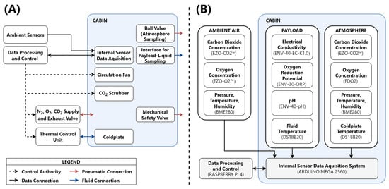
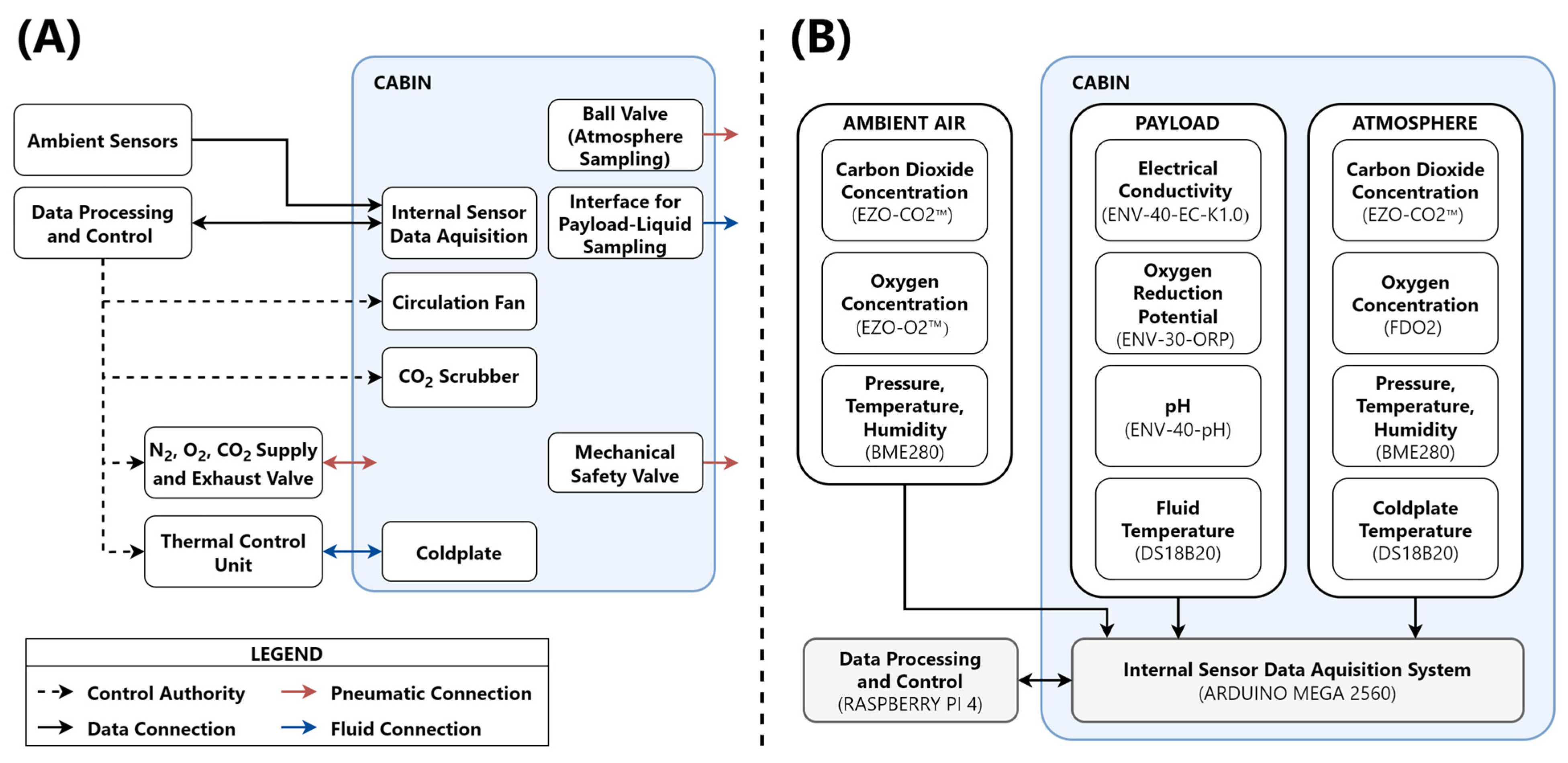
Together, the atmosphere and thermal control systems establish reproducible environmental boundary conditions by minimizing external influences on payload characterization. To support atmosphere management, cabin air circulation is provided by a fan (F14 PWM, ARCTIC GmbH, Braunschweig, Germany) with a maximum airflow rate of 126 m3h−1. CO2 removal is achieved using a calcium hydroxide-based scrubber. Further details are provided in Section Controller and Section 2.3.2. An overview of the system architecture is provided in Figure 1A, with sensor locations given in Figure 1B.
Figure 1.
Overview of the system architecture of the characterization environment. (A) showcases the overall system, where a control unit oversees system operations such as gas injection, CO2 removal and thermal control. This unit gathers housekeeping data from a microcontroller situated within the cabin. (B) provides a closer look at the decentralized sensor array with implemented components in brackets, managed by the microcontroller. Subsequently, the collected data is transferred to the Raspberry Pi for system control and operation.
2.2. Mechanical Design
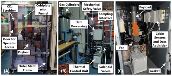
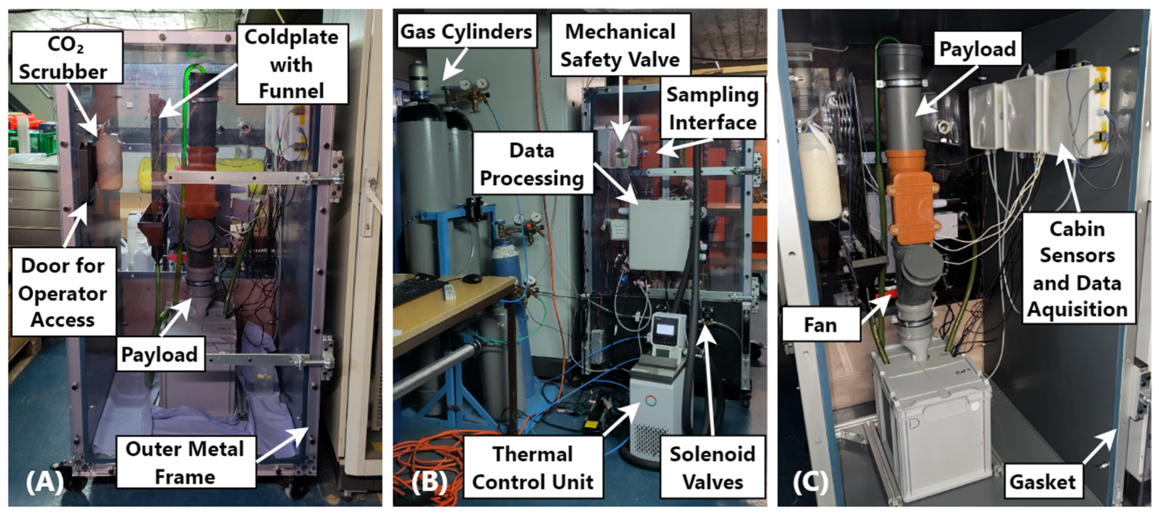
The characterization environment consists of a welded polyvinyl chloride (PVC) cabin (15 mm wall thickness) supported by an aluminum profile frame mounted on casters to facilitate transport and maintenance access. The internal cabin dimensions are 1350 mm × 840 mm × 720 mm, corresponding to an internal volume of 0.816 m3. The cabin dimensions and aspect ratio were selected to accommodate the C.R.O.P.®-system in its intended experimental configuration. However, the platform can accommodate other BLSS technologies that fit within the available cabin envelope. The cabin is enclosed by two transparent 20 mm thick polycarbonate (PC) doors located at the front and rear interfaces. The doors are mounted using a metal frame constructed from aluminum light series profiles (40 mm× 40 mm) with W80 × 80 × 40 corner brackets (both Item Industrietechnik, Germany). The front door provides operator access (Figure 2A), whereas the rear door accommodates the pneumatic, thermal, electrical and safety-related feedthroughs (Figure 2B). Figure 2C provides an insight into the cabin with an exemplary payload within. On the right wall are the electronic boxes that house and protect all measurement electronics from water vapor and uncontrolled condensation.
Figure 2.
Representation of the cabin setup. (A) showcases the cabin structure, which comprises a PVC frame enclosed in a metal profile housing with two PC doors. The image provides a view from the operator access side, featuring an exemplary payload—the DLR C.R.O.P.®-system—inside. The CO2 scrubber is situated on the left wall, while the coldplate with its condensate collection system is positioned next to the payload and the measurement electronics are located on the right wall. (B) presents the rear view of the cabin, with the gas cylinders on the left, the thermal control unit positioned to the front and a mechanical safety valve located on the top left door side. All electronics and sensors are housed within the mounted case for protection. (C) offers a view inside the cabin with the door open. On the right side, electronic boxes are visible, serving to protect the sensors and the microcontroller.
Although the system is not intended for continuous overpressure operation, the structural components were engineered to withstand differential pressures of up to 75 hPa to ensure operational robustness and personnel safety. Because the concept relies on minimizing passive gas exchange (Section 2.1), particular emphasis was placed on the sealing performance of all cabin interfaces. Therefore, closed-cell elastomer gaskets (Armaflex Ultima, 6 mm thickness, Armacell GmbH, Muenster, Germany) were implemented at the door interfaces. These gaskets are compressed to approximately 33% of their original thickness upon closure to ensure reproducible sealing performance.
2.3. Process Subsystems
2.3.1. Atmosphere Control
Safety Hardware Architecture
In order to ensure safe operation under both nominal and fault conditions, the gas supply is implemented as a multi-stage safety architecture. All gas cylinders (N2, O2 and CO2) are equipped with pressure regulators, while downstream flow restrictors and adjustable throttles limit and adjust the supplied gas flow. Normally closed solenoid valves serve as the interface to the characterization environment and provide a fail-safe mechanical shutoff in the event of power loss. In order to prevent excessive pressure buildup during fault conditions, a mechanical safety valve (AV619 1”, Witt-Gastechnik GmbH & Co KG, Witten, Germany) with a differential release pressure of 40 hPa and a flow capacity of 24.5 m3h−1 is implemented. This setup was verified as sufficient, even for a scenario in which gas cylinders are accidentally opened, as verified through simulation. Valve closure occurs at approximately 75% of the nominal release pressure. The exhaust is vented into the surrounding laboratory environment, which is equipped with CO2 and O2 warning systems. An additional solenoid valve enables active depressurization and controlled pressure equalization during operation.
Controller
As outlined in Section 2.1, the atmosphere controller regulates the cabin composition based on operator-defined setpoints for each of the three process gases. Accurate control of O2 and CO2 concentrations is essential because both gases directly reflect biological activity. They constitute the primary variables for payload characterization and gas exchange analysis.
Therefore, they serve as the central parameters of gas exchange rate monitoring and control actuation. In order to reduce system complexity, only O2, CO2 and water vapor concentrations are measured. N2 concentration is calculated using a residual-gas approach, that sums up all unquantified gas fractions according to:
where x denotes the volumetric fraction of each component. The atmosphere control utilizes a proportional controller (P-Controller) that employs pulse-width-modulated gas pulses to measure the input volume necessary for gas composition correction. This procedure was selected based on the anticipated slow metabolic dynamics of the integrated biological systems, which operate on timescales slower than the control interval. As a result, integral or derivative control components are not needed, simplifying the overall controller architecture.
By default, the atmosphere control system is set to the standard atmosphere composition, with the O2 concentration set at 21 ± 0.1% and the CO2 concentration at 0.04 ± 0.01%. These tolerance bands are intended to provide stable, nominal atmospheric boundary conditions for standard payload operation. As setpoints are often payload-specific, they can be adjusted individually. The system supports cabin pressures from ambient pressure up to +75 hPa maximal design pressure, temperatures from approximately 5–40 °C with the lower limit representing non-freezing operating conditions and the upper limit corresponding to the maximum ambient temperature considered in the thermal design (see Section 2.3.2) and relative humidity from ambient conditions up to 90% RH as experimentally verified. Gas-composition setpoints can be configured according to payload requirements within the technical and safety constraints of the system and are subject to prior safety assessment for non-standard operating conditions. The system is capable of maintaining considerable differences from ambient conditions to conduct stress testing and payload characterization under the specific conditions of the intended operation environment. Detailed verification is shown in Section 3.1.
The resulting control actions depend on the process-gas type and the direction of the deviation. Concentrations below the setpoints are uniformly corrected by pulsed injection of the corresponding process-gas. Excessive O2 levels are reduced by dilution with N2. As dilution is not effective for correcting elevated CO2 levels to the usually low setpoints, a scrubber is used for selective CO2 removal (described in Section 2.3.1). Valve opening durations are calculated from the deviation between measured (or calculated) concentrations and their corresponding setpoints. The resulting pulse duration additionally considers the configured mass flow rate of each process gas. The control interval is customizable within a range of 10 to 900 s, typically set to 300 s to reflect the slow payload metabolism and reduce valve wear. In order to further damp the response and limit overshoot, a pulse-duration limit is enforced at 50% of the control interval.
In order to characterize the dynamic response of the atmosphere control system and obtain the parameters required for controller implementation, the concentration change following a finite-duration gas pulse was modeled experimentally. The overall control behavior was characterized as a first order integrator with dead time. The corresponding time-domain response c(t) to a pulse input can be given by:
with
where t denotes time, td the dead time, tp the pulse duration and K the gas specific gain in vol.% s−1. The dead time td represents the total delay of the measurement and control chain. Because experimentally determined dead times varied slightly between measurements, a conservative safety margin was incorporated into the controller. For a pulse duration of tp = 100 s, the evaluated dead times were td (N2) = 12.94 ± 1.43 s and td (O2) = 11.14 ± 2.41 s. The dead time of CO2 could not be determined with similar precision, with discrepancies of up to 40%, owing to the system’s high sensitivity to minor CO2 doses, which can be attributed to the low overall CO2 concentration, the relatively slow sensor dynamics and a high susceptibility to incomplete cabin mixing. To ensure robust operation, a constant software dead time of td = 20 s, corresponding to the sensor acquisition interval, was implemented into the controller logic and experimentally verified to be sufficient for all process-gases. The gain K is determined from the concentration response ∆c induced by a pulse of duration tp.
CO2 Scrubbing
Because the target CO2 concentration represents only a small fraction of the cabin atmosphere, CO2 level reduction by dilution with O2 or N2 would require a comparatively large gas volume and unnecessarily increase the demand on the pressure-relief system. In order to efficiently lower CO2 concentrations, a CO2 scrubbing system was implemented to keep the cabin concentration within predefined operational thresholds. The scrubber consists of a container filled with a calcium hydroxide-based indicator lime and a rotary vane pump (G 12/02 EB, 12 VDC, 3.6 Lmin−1, Gardner Denver Thomas, LLC (Thomas Pumps), Sheboygan, WI, USA). Calcium hydroxide was selected because it provides passive, energy-efficient CO2 removal without requiring regeneration during the characterization experiments. The pump is installed downstream of the sorbent bed and continuously draws cabin air through the absorber, where CO2 is chemically bound. The treated air is returned into the cabin atmosphere, maintaining closed-loop operation.
In this process, CO2 is chemically bound according to:
The carbonation reaction is exothermic, with a standard reaction enthalpy of approximately ΔH°298K = −113 kJmol−1 CO2 [31]. The scrubber can be operated either in a threshold-based control mode, in which circulation is activated until a user-defined CO2 concentration is reached, or in a continuous mode to maximize CO2 removal. Its functional verification is presented in Section 3.2.
2.3.2. Thermal Control
The thermal control system ensures controlled condensation of water vapor and regulates the cabin air temperature. It deliberately conditions only the cabin atmosphere, while process-temperature regulation remains under the control of the individual payload. Uncontrolled condensation on internal surfaces and sensitive electronic components is prevented by maintaining the surface temperature of an internal coldplate below the dew point temperature of the cabin atmosphere. Directing condensation to the coldplate as a defined collection surface is particularly relevant with respect to payloads that involve aqueous process streams with associated evaporation. Examples include the DLR C.R.O.P.®-system envisioned to be characterized within the presented framework, as well as systems involving microbial cultures, algae, or higher plants. Condensed water is collected via a funnel system and returned to the payload-liquid reservoir, closing the internal water loop.
As outlined in Section 2.1, cabin air temperature has to be maintained below the payload-specific operating temperature to enable payload operations. There are two cases that the thermal system has to deal with. First, the payload target temperature lies below the cabin temperature. This would be achieved through a dedicated heat-transfer path to the coldplate, such as a heat strap. Meanwhile, condensation under high-humidity conditions remains controlled by the coldplate. This is a rather uncomplicated case for the thermal system.
The worst-case condition is thus defined by case two, in which the payload operates above cabin temperature, which increases evaporation and hence the risk of uncontrolled condensation. In this scenario, the thermal control system must dissipate sufficient heat to preserve the control authority of the payload-integrated heating systems.
The coldplate has a surface area of 0.37 m2 (HE500-S, RöHa Kellereibedarf, Gollhofen, Germany). Distilled water is used as the heat-transfer fluid. The required heat-removal capacity was determined using a steady state thermal model based on the finite difference method (FDM), employing 20 nodes to represent the dominant heat-transfer paths within the system. The model was implemented in MATLAB R2022a, ODEbox Version 1.1, Solver ode45 (The MathWorks, Inc., Natick, MA, USA). It was used to estimate the heat-removal rate required to preserve payload-integrated heater control authority under a worst-case ambient temperature of up to 40 °C, using a payload setpoint temperature of 28 °C. Under the conservative assumption of forced convective heat transfer across all external cabin walls and assuming a coldplate setpoint of 5 °C, the model yielded a maximum required heat-removal rate of 71 W. The implemented coldplate and thermal control system provide a cooling capacity of 200 W, corresponding to a safety factor of approximately 2.8 relative to the calculated worst-case requirement.
Via an USB-interface, the thermal control unit is connected to a single-board computer as the central data processing and control instance of the characterization environment. Cabin air temperature and water vapor concentration are continuously monitored. Thermal regulation is achieved by automated updates to the temperature setpoint of the thermal control unit.
2.4. Electrical and Sensor System
The electrical architecture comprises a distributed sensor network with separated systems for sensor data acquisition and supervisory control. Sensor acquisition inside the cabin is performed by a microcontroller. Supervisory control, data processing and long-term data management are executed by a single-board computer. Sensors communicate via I2C, UART and OneWire interfaces. The single-board computer coordinates these communication channels and stores all acquired data in a database to ensure robust storage of heterogeneous sensor data and system logs.
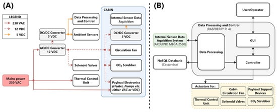
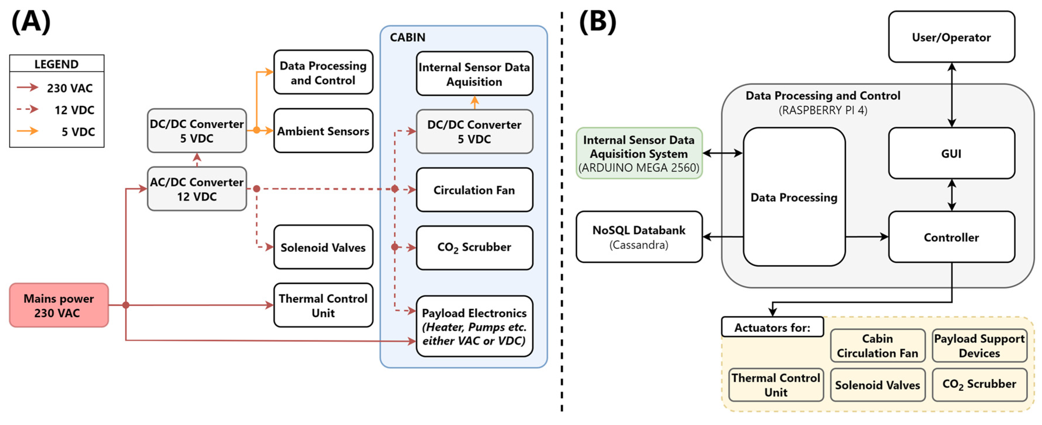
The architecture offers interfaces to electrical rails at voltage levels of 230 VAC, 12 VDC and 5 VDC to power electrical components for both, the characterization environment systems and the payload-specific electrical subsystems.
An overview on the power distribution is provided in Figure 3A.
Figure 3.
Overview of the power distribution and the data processing and control system. (A) Power distribution architecture. The overall system is connected to a 230 VAC mains supply, which feeds a central power-conversion stage generating 12 VDC. From this rail, 5 VDC supply rails are generated both inside and outside the cabin. All available voltage levels are accessible within the cabin for payload operation, providing flexibility for different test campaigns. (B) Schematic of the data-processing and control architecture. Central control is implemented on a Raspberry Pi 4 single-board computer, which receives sensor data from inside and outside the cabin via an Arduino Mega 2560 microcontroller (for a sensor overview, see Figure 1B). The acquired data are stored in a NoSQL database and used by the central control system to command the available actuators. User interaction with the control system is provided through a GUI.
2.4.1. Control Architecture and Data Acquisition
The microcontroller (Arduino Mega 2560, Arduino S.r.l., Monza (MB), Italy) interfaces with all sensors located inside the cabin and in the surrounding environment. The acquired data are locally preprocessed and assembled into timestamped structured data packets containing sensor identifiers and measured values before serial transmission. Central control is implemented on a single-board computer (Raspberry Pi 4 Model B, Raspberry Pi Foundation, Cambridge, UKwhich executes atmosphere control (gas input, CO2 scrubbing), thermal control and overall system supervision. It also handles database interfacing and graphical user interface (GUI) operation. The custom GUI provides real-time monitoring, user defined setpoint adjustment and experiment configuration. Data is stored in a locally hosted, distributed NoSQL database (Cassandra, The Apache Software Foundation, Los Angeles, CA, USA), which reliably supports long-duration experiments and provides efficient access for post-processing and external data analysis. Details are provided in Figure 3B.
The separation of real-time sensor acquisition and supervisory control has several benefits. It provides a robust modular sensor network without placing an excessively demanding computational effort on one processor. Furthermore, easy hardware replacement and integration of additional payload-specific sensors and actuators with minimal software modifications are enabled.
2.4.2. Sensor Array and Environmental Monitoring
The sensor array provides measurements of cabin atmosphere composition, environmental conditions and physicochemical properties of aqueous process solutions. Cabin atmosphere composition is monitored by optical O2 and CO2 sensors, with corresponding reference measurements obtained in ambient air. Cabin O2 concentration is determined from high precision partial pressure sensors (FDO2, PyroScience GmbH, Aachen, Germany). CO2 concentrations and all ambient reference measurements are obtained as volumetric fractions using EZO-O2™ and EZO-CO2™ sensors (Atlas Scientific LLC, Long Island City, NY, USA). These measurements serve as process parameters for the atmosphere control system, quantifying gas exchange between cabin and ambient atmosphere. Additionally, they support payload characterization by quantifying gas exchange between the payload and the cabin atmosphere.
Air temperature, relative humidity and pressure are measured using BME280 sensors (Robert Bosch GmbH, Gerlingen-Schillerhoehe, Germany) installed inside and outside the cabin. They allow the assessment of environmental stability within the cabin and the evaluation of its thermal and atmosphere decoupling from ambient conditions.
The physicochemical properties of aqueous process solutions can be instrumented with sensors measuring oxidation reduction potential (ORP), pH and electrical conductivity (EC), using probes from the ENV series (Atlas Scientific LLC, Long Island City, NY, USA). Fluid and internal housekeeping temperatures are monitored using DS18B20 sensors (Analog Devices Inc., Wilmington, MA, USA), enabling a correlation with the payload operation temperatures. A detailed list of sensors and associated interfaces is provided in Table 1. The corresponding sensor locations are shown in Figure 1B.
Table 1.
Overview of sensors implemented in the characterization environment.
3. System Verification
3.1. Cabin Atmosphere Stability
This section evaluates the ability of the characterization environment to maintain stable atmosphere conditions under near-ambient pressure by minimizing passive gas exchange with the surrounding environment, as described in Section 2.1 and detailed in Section 2.3.1.
In order to assess cabin atmosphere stability with respect to the central process-gases O2 and CO2, two long-duration experiments were conducted. The cabin was sealed and an initial concentration gradient relative to ambient conditions was established using the atmosphere control system.
In experiment 1, only the O2 concentration was reduced, resulting in an initial cabin concentration of 16 vol.% O2 (ambient approx. 20 vol.%). In experiment 2, only the CO2 concentration was increased to 1.15 vol.% (ambient approx. 0.06 vol.%), while the remaining atmosphere composition was otherwise left unchanged.
Subsequently, the exhaust valve was opened to relieve residual overpressure and no further control actuation was applied. The atmosphere control system was intentionally deactivated for the remainder of the experiment, allowing the passive concentration drift of the sealed cabin to be quantified directly.
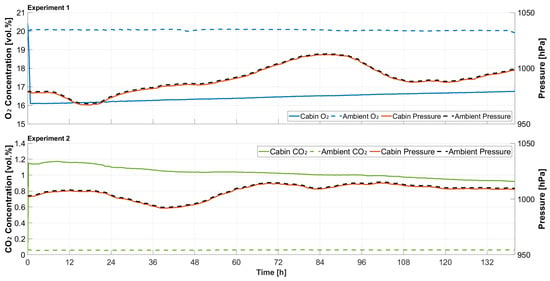
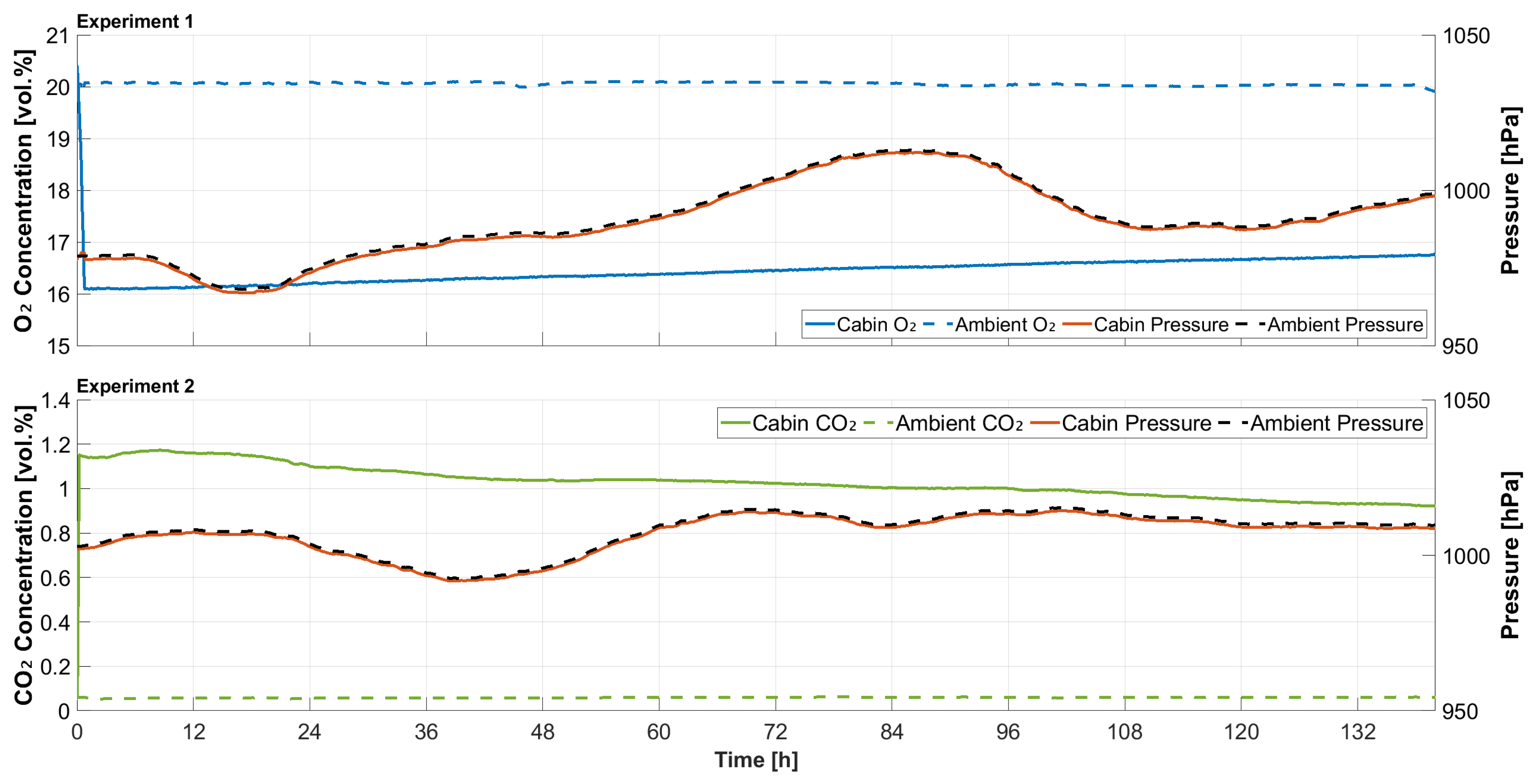
O2 and CO2 concentrations were monitored in their respective test runs for approximately 140 h to evaluate long-term concentration drift under equalized pressure conditions. Environmental parameters were recorded at a sampling interval of 120 s. Results are presented in Figure 4.
Figure 4.
Graphical representation of long-term O2 (experiment 1, top panel) and CO2 (experiment 2, lower panel) concentration evaluations following the introduction of an initial concentration gradient relative to ambient conditions. The comparison includes pressure variations in both the cabin and ambient environment. In each experiment run, the atmosphere control system established the target gradient, followed by pressure relief through the exhaust valve. Concentration changes were monitored passively without further control actuation.
Both experiments demonstrated sufficiently stable atmosphere isolation over the entire observation period, with only a slow, nearly linear change in concentrations. As active atmosphere control was disabled during these experiments, the observed concentration changes reflect passive drift and are consistent with a low gas-exchange rate driven by concentration gradients between the cabin atmosphere and its surroundings. The O2 concentration increased by approximately 0.7 vol.%. The CO2 concentration exhibited a slight initial increase by approximately 0.05 vol.% during the first 24 h, which coincided with a transient pressure variation of about 0.1 hPa, both in the cabin and the ambient conditions. Over the full measurement period, the CO2 concentration decreased by approximately 0.15 vol.%.
Linear regression yielded concentration drift rates of 0.0049 vol.%h−1 for O2 and −0.0016 vol.%h−1 for CO2. The equations are given below, with t expressed in hours and concentrations given in vol.%:
In order to assess the level of atmosphere isolation, the concentration drifts were converted into apparent air-change rates (ACH). These consider the effective exchange of cabin air with the ambient environment, indicating how rapid an imposed cabin atmosphere condition would be diluted by ambient air. Assuming a well-mixed cabin atmosphere and concentration-driven gas exchange, , was estimated from:
where and denote the cabin and ambient volumetric fractions of gas component i, respectively. Because the measured concentration drift was minimal compared to the imposed concentration differences during the 140 h observation period, the gradients were approximated by their initial values:
and
For the cabin volume of 816 L, these values correspond to an apparent air exchange of 1.0 Lh−1 for O2 and 1.2 Lh−1 for CO2, serving as the correction factors to implement in characterizing payload gas exchange. The observed drift rates are substantially slower than the concentration changes expected from biological gas exchange during payload operation. Representative volumetric gas exchange rates reported for an 83 L MELiSSA Pilot Plant photobioreactor operated with the cyanobacterium Limnospira indica correspond to 0.31–1.04 g-O2 L−1d−1 production and 0.29–1.13 g-CO2 L−1d−1 uptake under the investigated steady-state operating conditions [32]. For complete nitrification, the theoretical oxygen demand for the oxidation of ammonium nitrogen (NH4-N) to nitrate nitrogen (NO3-N) is 4.57 g-O2 g-N−1 [33], while experimental measurements reported a similar specific oxygen uptake of 4.23 g-O2 g-N−1 [34] oxidized.
The measured passive cabin drift represents a comparatively small and quantifiable background contribution during payload operation. Only limited corrective actuation is therefore required to compensate for this drift during nominal payload characterization, for which correction factors can be applied when determining effective payload gas-exchange rates.
Overall, the experiments conducted within this work demonstrate that the characterization environment maintains stable atmosphere conditions with only minimal passive gas exchange over at least 140 h. The resulting low apparent air-change rate enables payload-induced gas exchange to be distinguished from passive concentration drift using the drift rates given above, thereby fulfilling one of the principal design objectives of the characterization environment.
3.2. Verification of CO2 Scrubber
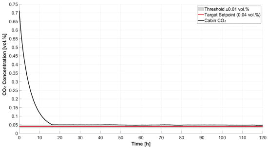
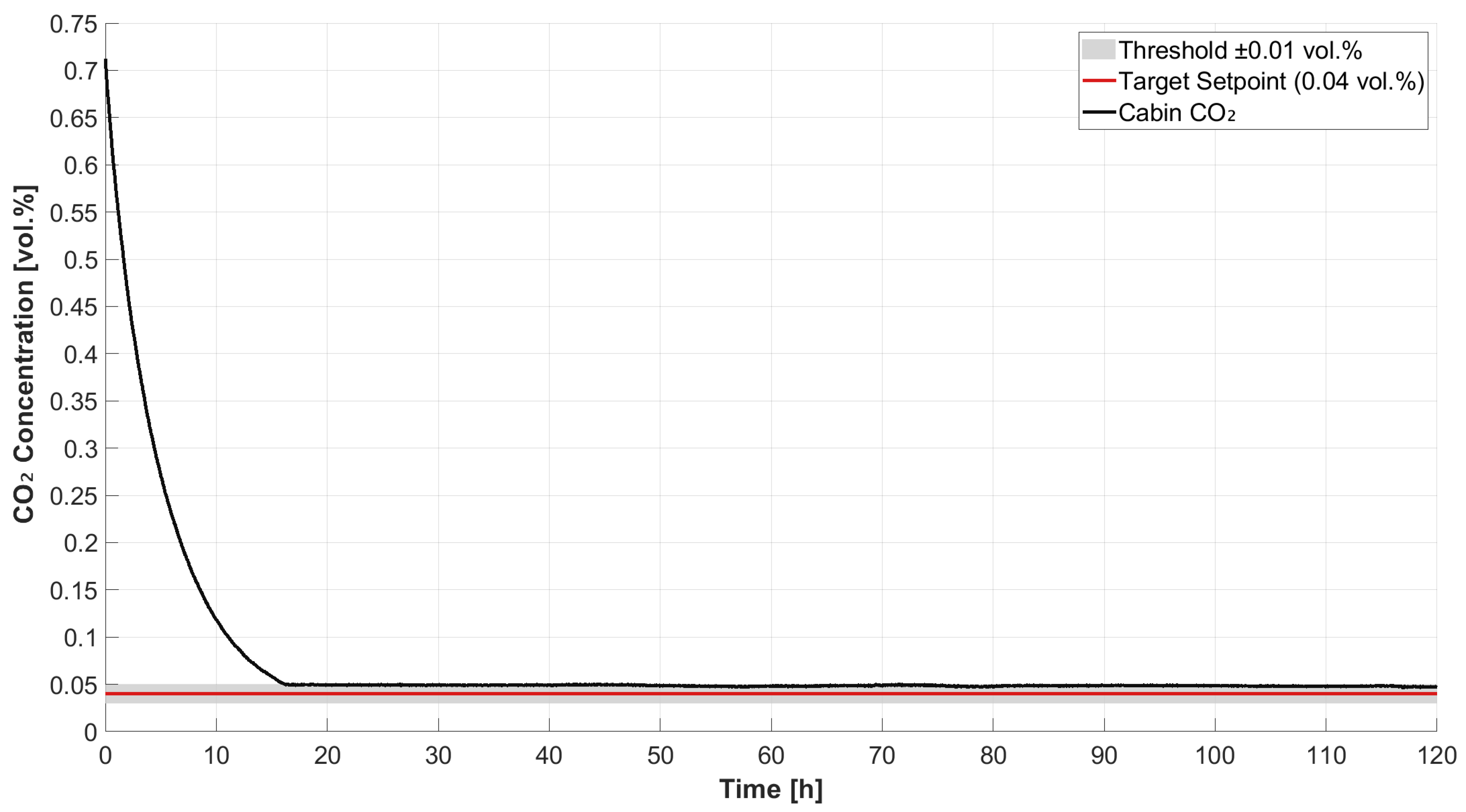
The functionality of the CO2 scrubber was evaluated in a system-level experiment. An elevated cabin CO2 concentration was established by applying a controller-induced step input, resulting in an initial concentration of 0.71 vol.% CO2. Subsequently, the controller setpoint was adjusted to 0.04 vol.% with a tolerance band of ±0.01 vol.% and a control interval of 100 s. Following detection of the elevated CO2 concentration, the controller activated the CO2 scrubber. No N2 and O2 injection was applied, ensuring that the observed concentration decrease resulted exclusively from CO2 removal.
The scrubber reduced the CO2 concentration continuously from 0.71 vol.% to 0.049 vol.% within approximately 16 h, corresponding to a reduction of approximately 93% relative to the initial concentration (Figure 5). Throughout the entire experiment lasting 120 h, the decrease in CO2. concentration corresponded to a mass reduction of 9.86 g-CO2. The majority of the concentration decrease (approximately 75%) took place within the initial 6.5 h. Afterwards, the removal rate gradually decreased as the concentration approached the target range. A first-order exponential approach-to-equilibrium model was fitted to the measured concentration profile:
where t is given in hours, c0 represents the initial concentration in vol.%, c∞ the asymptotic concentration in vol.% and k represents the decay constant in h−1. Curve fitting yielded c∞ = 0.049 vol.%, c0 = 0.71 vol.% and k = 0.22.
Figure 5.
Development of the cabin CO2 concentration (vol.%) as a function of time (h) during the CO2 scrubber verification test. The red line denotes the target CO2 concentration and the shaded area indicates the permissible tolerance band.
Once the CO2 concentration entered the specified tolerance band, the scrubber pump was deactivated automatically. The concentration subsequently remained stable under passive conditions until the experiment was terminated after 120 h. No further control action was required to maintain the target range.
The imposed reduction of 0.67 vol.% represents a worst-case operating scenario that exceeds the concentration deviations expected during routine payload operation. During routine operation, payload-specific threshold values can be configured by the operator, allowing scrubber activation before substantial deviations occur. Overall, the results demonstrate that the scrubber reliably reduces elevated CO2 concentrations within predefined operational limits, thereby validating the proposed atmosphere-control concept.
3.3. Closed-Loop Validation of Controller Performance
The closed-loop performance of the atmosphere control system was evaluated using independent O2 and CO2 setpoint step tests. The experiments were designed to verify the controller performance under closed-loop operation using the controller architecture described in Section 2.3.1.
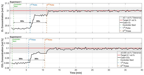
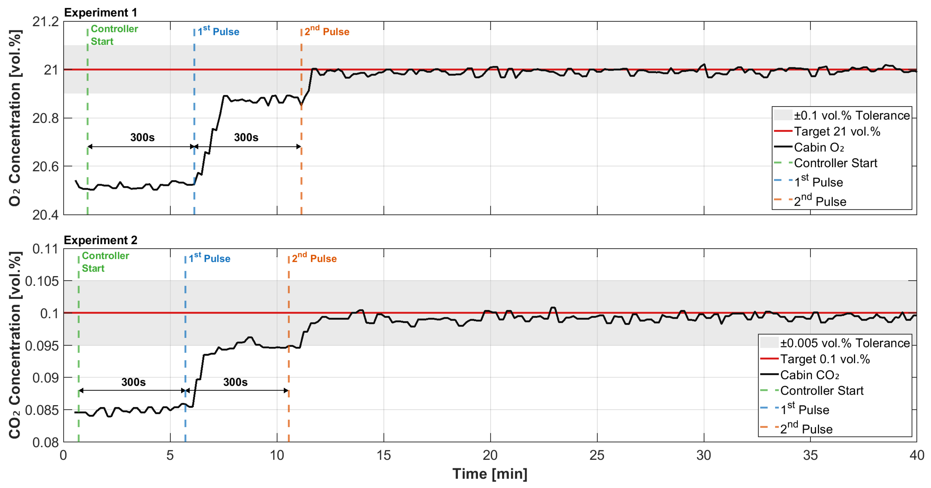
Following an initial steady-state idle phase, the setpoints were modified by +0.5 vol.% for O2 and +0.015 vol.% for CO2. Subsequently, the control system was switched to automatic operation. Concentration deviations were evaluated at control intervals of 300 s. Corrective gas pulses were initiated whenever the measured concentration exceeded the predefined tolerance band of ±0.1 vol.% for O2 or ±0.005 vol.% for CO2.
Figure 6 shows the resulting system response. For both gases, the controller reached the target concentration within two corrective pulses and subsequently maintained the concentration within the specified tolerance band without further actuation. The O2 response (experiment 1, upper panel) required pulses of tp1 (O2) = 88 s and tp2 (O2) = 27.5 s. The CO2 response (experiment 2, lower panel) required pulses of tp1 (CO2) = 93 s and tp2 (CO2) = 20.4 s. The corresponding injected gas masses were 5.32 g-O2 and 0.205 g-CO2.
Figure 6.
Visualization of the setpoint target control for oxygen (experiment 1, top panel) and carbon dioxide (experiment 2, lower panel) in relation to the controller target setpoints. The P-controller adjusts the pulse duration, with a maximum enforced at 50% of the control frequency (here: 300 s), after which the need for another pulse is reassessed. Y-Axes show the gas concentration in vol.%, for O2 and CO2, while the X-Axes show the time in minutes. Target setpoints are given as a red line, with a tolerance band shaded in gray.
No measurable overshoot was observed in either O2 or CO2 responses within the resolution of the integrated sensors. Small fluctuations around the setpoint were observed (Figure 6); however, these remained within the sensor noise band. Additional validation experiments demonstrated convergence within a maximum of three corrective pulses under all investigated operating conditions. Larger initial deviations required additional pulses because of the bounded pulse-width limit at 50% of the control interval. These results confirm that the proportional-control architecture is sufficient for the slow and strongly damped atmosphere dynamics expected for BLSS payloads. If necessary, the control interval can be adjusted depending on payload requirements, as described in Section 2.3.1. Longer intervals reduce actuator wear, while shorter intervals improve responsiveness at the cost of increased waste process-gas. This provides flexibility for adapting the control system to different experimental payloads and higher metabolic gas exchange rates than currently anticipated. These experiments characterize the intrinsic controller dynamics in the absence of biological gas exchange and therefore establish the baseline control performance of the characterization environment.
3.4. Stress Test of Controller Performance
In order to evaluate controller robustness under worst-case atmosphere loading, a continuous disturbance was intentionally introduced, exceeding operational limits. A tea light (12 g plant-based wax and paraffin wax blend, ṁ ~ 3 gh−1) was placed inside the cabin to provide a continuous source of O2 consumption and CO2 production. Although combustion does not reproduce the stoichiometry of biological metabolism, it provides a stable and reproducible worst-case disturbance for evaluating controller robustness. During this experiment, the CO2 scrubber system was deactivated. This configuration, represents a combined atmosphere load exceeding the expected gas exchange rates of biological payloads.
The O2 control system was operated in automated mode with a control interval of 300 s. At each control cycle, the measured O2 concentration was compared to the target setpoint of 20.95 vol.%. An O2 injection pulse was initiated when the concentration deviated beyond the tolerance band of ±0.1 vol.%.
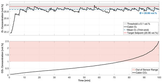
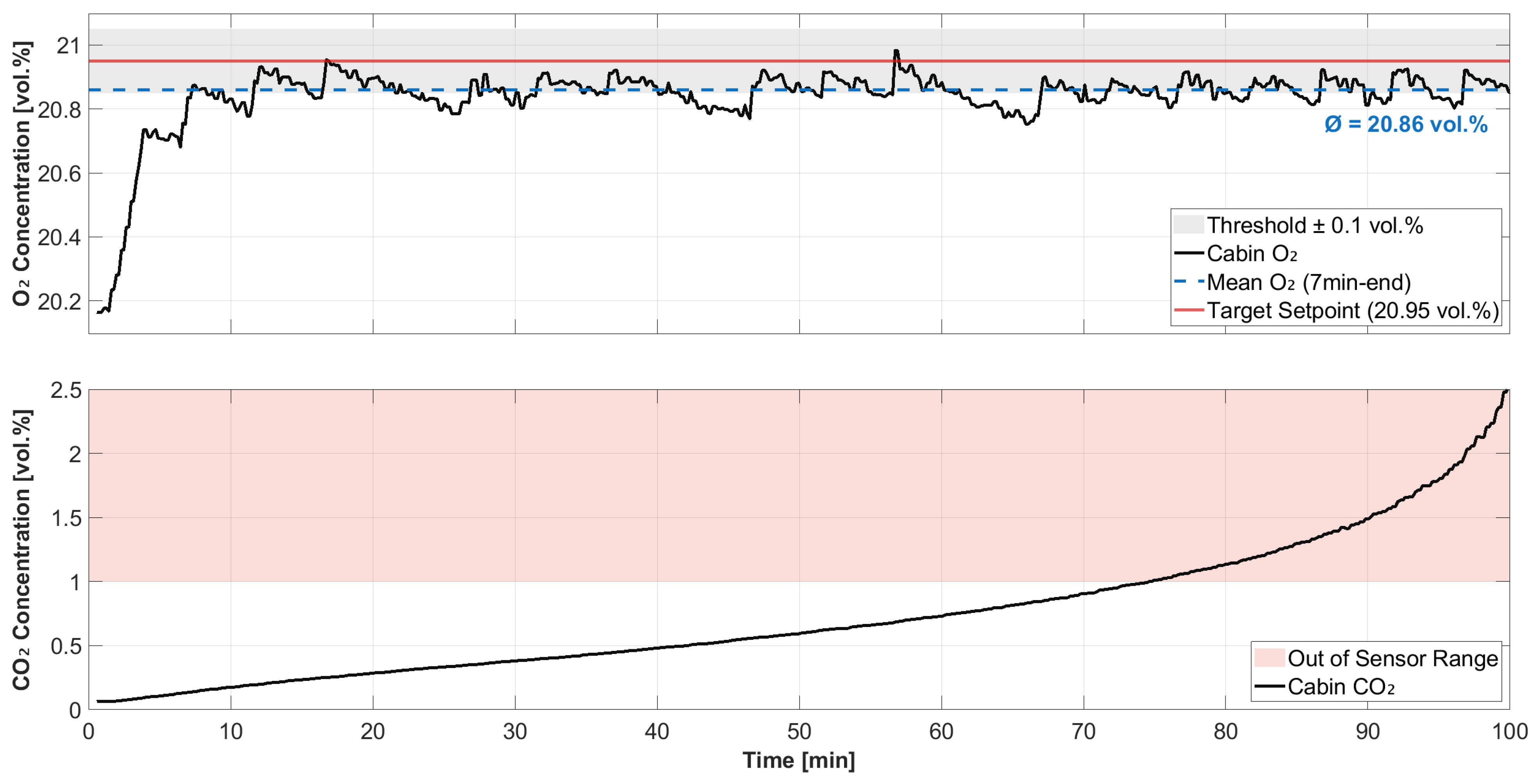
Figure 7 shows the resulting O2 and CO2 concentrations within the cabin over the approximately 100 min experiment. Periodic O2 injection pulses compensated for the continuous O2 consumption, producing sharp concentration increases followed by gradual decreases between control actions. From minute 7 onwards, the mean O2 concentration was 20.86 vol.%, corresponding to a bias toward the lower tolerance boundary. This behavior is attributed to the control setup, which utilizes pulse-width-modulated gas injection based on the deviation between measured or calculated concentrations and their respective target values. Additionally, the implementation of a pulse-duration limit contributes to the tendency towards the lower boundary. However, the concentration remained consistently within the specified tolerance band and no sustained excursions beyond the control limits were observed.
Figure 7.
Evaluation of atmosphere control accuracy under a sustained disturbance. A tea light candle was placed inside the cabin to impose simultaneous O2 consumption and CO2 generation. In order to stress test the atmosphere control system exceeding operational boundaries, the CO2 scrubber was deactivated, resulting in the control system relying solely on an injection-based control approach. The graph displays the O2 concentration in the upper panel and the corresponding CO2 concentration in the lower panel over time. Gas concentrations are represented in vol.% on the Y-Axes, while time is shown in minutes on the X-Axes. The O2 concentration exhibits a lower boundary tendency due to the pulse-width determination process and a corresponding pulse-duration limit. Despite this tendency, the mean O2 level remains within the required target threshold.
The cumulative O2 valve actuation time was approximately 604 s, corresponding to an estimated total O2 injection mass of 16.2 g. The imposed O2 consumption rate was approximately 0.16 gmin−1. The CO2 concentration increased continuously and exceeded the sensor measurement range after approximately 74 min because active CO2 removal was intentionally disabled.
Overall, the controller maintained the O2 concentration close to the targeted setpoint under continuous O2 consumption and simultaneous CO2 accumulation under stress test conditions, supporting system suitability for biological payload operation.
3.5. Thermal Control Verification
The thermal control system was evaluated in a combined experiment addressing its two principal functions. As outlined in Section 2.3.2, the first objective was to provide sufficient heat-removal capacity to maintain the cabin air temperature below the payload-specific operating temperature. The second objective was to provide reliable condensation guidance.
In order to impose simultaneous thermal and humidity loads, an uncovered fluid reservoir containing approximately 10 L of water and equipped with a 100 W bimetallic heater (Hydor, Ferplast S.p.A, Castelgomberto (VI), Italy) was placed inside the sealed cabin as a payload-surrogate. The heater was operated at a setpoint of 30 °C (payload-specific operating temperature) and providing a continuous internal heat load, representative of a thermally active aqueous BLSS payload, while generating water vapor through evaporation. The cabin was closed and the system was operated continuously for 120 h, with ambient laboratory temperatures reaching a daily peak of approximately 27–28 °C. The thermal control unit was operated with a constant temperature setpoint of 10 °C. A collection vessel was positioned beneath the coldplate to quantify the recovered condensate. Cabin air temperature, relative humidity and payload-surrogate fluid temperature were monitored continuously throughout the experiment.
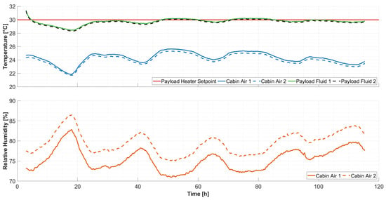
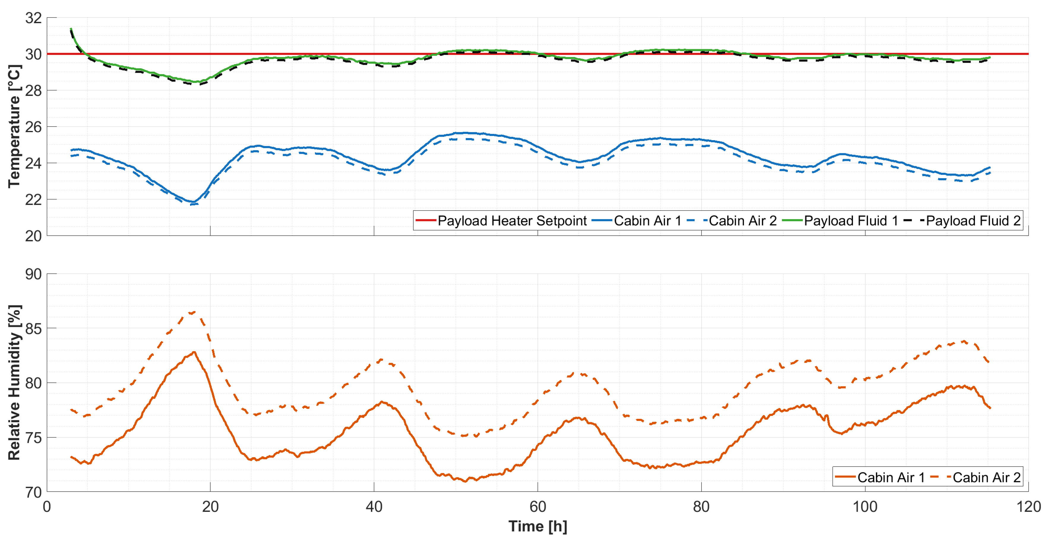
The coldplate remained the principal condensation surface. No uncontrolled condensation formation was observed on the cabin structure, sensors, or internal electronic components. Despite the continuous internal heat input, the cabin air temperature remained between approximately 21.7 °C and 25.5 °C, while the reservoir fluid stabilized at approximately 30 °C under control of the bimetallic heater.
Mean cabin air temperatures were TAir1 = 24.32 °C (σ = 0.83 °C) and TAir2 = 24.03 °C (σ = 0.80 °C). Mean fluid temperatures were TFluid1 = 29.78 °C (σ = 0.50 °C) and TFluid2 = 29.66 °C (σ = 0.51 °C). Relative humidity varied inversely with air temperature, while sustained condensation occurred at the coldplate. Mean relative humidities were RHAir1 = 75.35% (σ = 2.81%) and RHAir2 = 79.45% (σ = 2.77%).
A water mass balance was determined using a laboratory scale (CP4202S, Sartorius AG, Goettingen, Germany) with a maximum capacity of 4.2 kg. Because the measurement range was surpassed by the total water mass, weighing was performed in several fractions, introducing a cumulative weighing error. The initial mass of the payload-surrogate fluid was 10.42 kg, whereas 7.89 kg remained after the experiment, corresponding to a mass reduction of 2.53 kg. The condensate collection vessel contained 2.47 kg of recovered water. The combined final mass was therefore 10.36 kg, resulting in an unaccounted mass difference of 60 g, equivalent to approximately 2.35% of the evaporated water mass. Considering the experimental setup and the multiple weighing steps required, the remaining mass difference is small and confirms effective condensate recovery. The difference is primarily attributed to accumulated weighing uncertainty and residual water adhering to the coldplate and collection surfaces.
As shown in Figure 8, relative humidity remained stable around the mean of about 75–80% RH over the total experiment span despite continuous evaporation from the heated reservoir. Together with sustained condensate recovery at the designated condensation surface, this demonstrates that the thermal control system effectively limited moisture accumulation while maintaining the required cabin temperature below the payload-specific operating temperature, thereby fulfilling the design requirements.
Figure 8.
Thermal control verification experiment over the span of approximately 120 h at a room temperature maximum of approximately 27–28 °C per day. The upper panel shows the cabin air and payload-surrogate fluid temperatures. The fluid was heated using a 100 W bimetallic heater set to 30 °C, while the thermal control system maintained the cabin air temperature below the fluid temperature, thereby preserving the control authority of the payload-integrated heater. The lower panel shows the cabin relative humidity. Despite evaporation of approximately 2.5 kg of water during the experiment, relative humidity exhibited no accumulation and condensation was reliably enforced on the designated coldplate surface, with no relevant condensation observed elsewhere in the cabin. The periodic variations in temperature and relative humidity are attributed to ambient day and night cycle.
4. Discussion and Outlook
The presented platform was developed as a modular characterization environment for BLSS payloads, providing reproducible environmental boundary conditions, long-duration operation stability and independent control of the cabin N2, O2 and CO2 composition within the presented limitations. It addresses an intermediate stage in BLSS system or technology development. Large facilities such as the MELiSSA Pilot Plant, Lunar Palace 1 and the CEEF enable investigation of integrated biological processes, crop production and human-in-the-loop operation. However, their scale and operational complexity make prior subsystem maturation and characterization necessary before integration. The characterization environment serves as a cost-effective precursor, allowing for the preliminary payload characterization in terms of gas exchange rates and responses to non-nominal conditions while substantially reducing the engineering risk associated with integration into larger BLSS facilities. This approach helps bridging the gap between laboratory-scale technology demonstration and integrated BLSS testing.
The verification experiments demonstrated that defined O2 and CO2 concentration offsets relative to ambient conditions can be set and maintained over extended periods up to week(s). The observed passive concentration drift remained small compared with the gas exchange expected from biological payloads (see Section 3.1), confirming that atmosphere leakage is unlikely to interfere with quantitative payload characterization. This indicates that leakage rates are sufficiently low to enable payload gas exchange characterization. The corresponding drift rates were quantified to serve as correction factors for payload gas exchange characterization (see Section 3.1).
The proportional pulse-width controller proved to be sufficient for the slow atmosphere dynamics of the intended application. The absence of measurable overshoot experimentally confirms the design decision to omit integral and derivative control components (see Section 3.3). Future adaptations involving faster dynamics or different payload characteristics may, however, require retuning or extension of the control architecture.
Moreover, stress testing above the operational boundaries confirmed the controller’s ability to maintain the O2 setpoint even under disturbance loads with respect to elevated O2 consumption and simultaneous CO2 accumulation (see Section 3.4). The observed lower boundary bias is attributed to the employed pulse-width modulation of gas injection and the pulse-duration limitation. This configuration damps the control inputs, limiting overshoot and valve actuation but exhibits a conservative control behavior, aggravated by the high disturbance rate imposed by the candle. Balancing competing priorities is necessary, as shorter control intervals or increased proportional gain could improve responsiveness, but would increase valve actuation, process-gas consumption and potentially overshoot.
The verification of the CO2 scrubber demonstrated its capability to actively decrease elevated CO2 concentrations within the specified range, even in a stress test condition of elevated concentrations (see Section 3.2). Although the calcium-hydroxide scrubber exhibits comparatively slow dynamics, its response is well matched to the slow gas exchange expected from BLSS payloads. Consequently, the observed behavior does not constitute a practical limitation for the intended application.
The thermal control system combines two functions that were validated in a common experiment, the preservation of payload-integrated heater control authority and controlled removal of air water vapor to prevent uncontrolled condensation. During the 120 h experiment, the cabin air remained below the heated payload-surrogate temperature, ensuring heater control authority. The experiment confirmed simultaneous preservation of payload heater authority and controlled condensate recovery, thereby validating the integrated thermal-management concept (see Section 3.5).
Together, these verification experiments demonstrated that the platform provides the environmental stability required for quantitative characterization of BLSS payloads under controlled atmosphere conditions.
Several limitations of the current implementation should be acknowledged. First, atmosphere control relies on indirect determination of N2 concentration through a residual gas approach. While suitable for the intended operation conditions, this method assumes that the cabin atmosphere consists of N2, O2, CO2 and water vapor, only. Residual components are attributed to the predominant fraction of N2. Future applications may, therefore, require enhanced sensing capabilities. For example, periodic gas chromatography samples withdrawn through the gas-sampling interface could serve to independently validate the residual-gas approach during future payload experiments. Beyond atmosphere composition control, the gas- and liquid sampling interfaces enable analysis of contaminants in the cabin atmosphere and potentially harmful algal or microbial growth in the payload, particularly with respect to astronaut safety in future BLSS applications. A further limitation is, that the current work primarily focused on engineering validation of the platform itself and did not yet include a systematic characterization of biological payload performance. As an outcome, the reported results demonstrate the controllability of the cabin environment but not yet the payload dynamics.
Beyond its original purpose of supporting qualification of the DLR C.R.O.P.®-system nitrification system, the modular design enables implementation of a broader range of bioregenerative and environmental-control technologies. In the long term, it could be envisioned to establish multiple cabins in decentralized locations for the local validation of various BLSS technologies, for example through virtual coupling via the open-source simulation tool V-HAB [35]. The presented characterization environment provides a reproducible, modular and extensible engineering platform for quantitative BLSS payload characterization. By enabling standardized subsystem qualification prior to integration into larger BLSS facilities, it represents an important enabling technology for future biological life-support development and spaceflight experimentation.
Author Contributions
Conceptualization, I.M.H.; methodology, I.M.H., M.K., S.K. and G.B.; software, I.M.H. and M.K.; validation, I.M.H., M.K. and S.K.; formal analysis, I.M.H.; investigation, I.M.H., M.K. and S.K.; resources, I.M.H.; data curation, I.M.H., M.K. and S.K.; writing—original draft preparation, I.M.H.; writing—review and editing, I.M.H.; visualization, I.M.H.; supervision, J.H. and G.B.; project administration, J.H. and G.B.; funding acquisition, J.H. and G.B. All authors have read and agreed to the published version of the manuscript.
Funding
This research received no external funding.
Data Availability Statement
The data that support the findings of this study are available from the corresponding author upon reasonable request.
Acknowledgments
The authors would like to thank PyroScience GmbH, Germany for the generous donation of the two FDO2 sensors, which enabled the precise data collection for this research. In addition, the authors would like to thank Markus Czupalla, his student Moritz Adams and the entire spaceLab team at Aachen University of Applied Sciences (FH Aachen), as well as the DAISY student project at FH Aachen for their collaboration in the effort to build closed qualification environments for BLSS and for the lively exchange over the past few years. During the preparation of this work the authors used a local instance of ChatGPT-4.0 to improve the readability and language. The authors have reviewed and edited the output and take full responsibility for the content of this publication.
Conflicts of Interest
The authors declare no conflicts of interest.
Abbreviations
The following abbreviations are used in this manuscript:
| ACH | Apparent Air-change Rates |
| BLSS | Bioregenerative Life Support Systems |
| CO2 | Carbon Dioxide |
| CEEF | Closed Ecology Experiment Facility |
| COTS | Commercial off-the-shelf |
| C.R.O.P.® | Combined Regenerative Organic food Production |
| DLR | German Aerospace Center |
| EC | Electrical Conductivity |
| ESA | European Space Agency |
| GUI | Graphical User Interface |
| ISS | International Space Station |
| LEO | Low Earth Orbit |
| MELiSSA | Micro-Ecological Life Support System Alternative |
| NASA | National Aeronautics and Space Administration |
| N2 | Nitrogen |
| O2 | Oxygen |
| ORP | Oxidation Reduction Potential |
| PC | Polycarbonate |
| PVC | Polyvinyl Chloride |
| P-Controller | Proportional Controller |
References
- Mitchell, C.A. Bioregenerative life-support systems. Am. J. Clin. Nutr. 1994, 60, 820S–824S. [Google Scholar] [CrossRef] [Scilit]
- Hendrickx, L.; De Wever, H.; Hermans, V.; Mastroleo, F.; Morin, N.; Wilmotte, A.; Janssen, P.; Mergeay, M. Microbial ecology of the closed artificial ecosystem MELiSSA (Micro-Ecological Life Support System Alternative): Reinventing and compartmentalizing the Earth’s food and oxygen regeneration system for long-haul space exploration missions. Res. Microbiol. 2006, 157, 77–86. [Google Scholar] [CrossRef] [Scilit]
- Wheeler, R.M.; Stutte, G.W.; Subbarao, G.V.; Yorio, N.C. Plant growth and human life support for space travel. In Handbook of Plant and Crop Physiology; CRC Press: Boca Raton, FL, USA, 2001; pp. 947–964. [Google Scholar]
- De Micco, V.; Amitrano, C.; Mastroleo, F.; Aronne, G.; Battistelli, A.; Carnero-Diaz, E.; De Pascale, S.; Detrell, G.; Dussap, C.G.; Ganigué, R.; et al. Plant and microbial science and technology as cornerstones to Bioregenerative Life Support Systems in space. npj Microgravity 2023, 9, 69. [Google Scholar] [CrossRef] [Scilit]
- Zeidler, C.; Woeckner, G.; Schöning, J.; Vrakking, V.; Zabel, P.; Dorn, M.; Schubert, D.; Steckelberg, B.; Stakemann, J. Crew time and workload in the EDEN ISS greenhouse in Antarctica. Life Sci. Space Res. 2021, 31, 131–149. [Google Scholar] [CrossRef] [Scilit]
- Clauwaert, P.; Muys, M.; Alloul, A.; De Paepe, J.; Luther, A.; Sun, X.; Ilgrande, C.; Christiaens, M.E.; Hu, X.; Zhang, D.; et al. Nitrogen cycling in Bioregenerative Life Support Systems: Challenges for waste refinery and food production processes. Prog. Aerosp. Sci. 2017, 91, 87–98. [Google Scholar] [CrossRef] [Scilit]
- Hauslage, J.; Strauch, S.M.; Eßmann, O.; Haag, F.W.M.; Richter, P.; Krüger, J.; Stoltze, J.; Becker, I.; Nasir, A.; Bornemann, G.; et al. Eu:CROPIS—“Euglena gracilis: Combined Regenerative Organic-food Production in Space”—A Space Experiment Testing Biological Life Support Systems Under Lunar And Martian Gravity. Microgravity Sci. Technol. 2018, 30, 933–942. [Google Scholar] [CrossRef] [Scilit]
- Salisbury, F.B.; Gitelson, J.I.; Lisovsky, G.M. Bios-3: Siberian Experiments in Bioregenerative Life Support: Attempts to purify air and grow food for space exploration in a sealed environment began in 1972. BioScience 1997, 47, 575–585. [Google Scholar]
- Nelson, M.; Burgess, T.L.; Alling, A.; Alvarez-Romo, N.; Dempster, W.F.; Walford, R.L.; Allen, J.P. Using a Closed Ecological System to Study Earth’s Biosphere: Initial results from Biosphere 2. BioScience 1993, 43, 225–236. [Google Scholar]
- Nitta, K.; Otsubo, K.; Ashida, A. Integration test project of CEEF—A test bed for closed ecological life support systems. Adv. Space Res. 2000, 26, 335–338. [Google Scholar] [CrossRef] [Scilit]
- Zhao, T.; Liu, G.; Liu, D.; Yi, Y.; Xie, B.; Liu, H. Water recycle system in an artificial closed ecosystem—Lunar Palace 1: Treatment performance and microbial evolution. Sci. Total Environ. 2022, 806, 151370. [Google Scholar] [CrossRef] [Scilit]
- Fu, Y.; Liu, H.; Liu, D.; Hu, D.; Xie, B.; Liu, G.; Yi, Z.; Liu, H. A case for supporting human long-term survival on the moon: “Lunar Palace 365” mission. Acta Astronaut. 2025, 228, 131–140. [Google Scholar] [CrossRef] [Scilit]
- Lasseur, C.; Brunet, J.; De Weever, H.; Dixon, M.; Dussap, G.; Godia, F.; Leys, N.; Mergeay, M.; Van Der Straeten, D. MELiSSA: The European project of closed life support system. Gravitational Space Res. 2010, 23, 3–12. [Google Scholar]
- Wheeler, R. System Development and Early Biological Tests in NASA’s Biomass Production Chamber; National Aeronautics and Space Administration, John F. Kennedy Space Center: Merritt Island, FA, USA, 1990; Volume 103494.
- Feles, S.; Holbeck, I.M.; Hauslage, J. From Lab to Launchpad: A Modular Transport Incubator for Controlled Thermal and Power Conditions of Spaceflight Payloads. Instruments 2025, 9, 21. [Google Scholar] [CrossRef] [Scilit]
- Feles, S.; Keßler, R.; Hauslage, J. Pioneering the Future of Experimental Space Hardware: MiniFix-a Fully 3D-Printed and Highly Adaptable System for Biological Fixation in Space. Microgravity Sci. Technol. 2025, 37, 22. [Google Scholar] [CrossRef] [Scilit]
- Holbeck, I.M.; Sturm, M.; Feles, S.; Schunk, S.; Liemersdorf, C.; Hauslage, J. The LIFT Module: A Modular Fixation Platform for Biological Research on Sounding Rockets. Microgravity Sci. Technol. 2026, 38, 68. [Google Scholar] [CrossRef] [Scilit]
- Gòdia, F.; Albiol, J.; Pérez, J.; Creus, N.; Cabello, F.; Montràs, A.; Masot, A.; Lasseur, C. The MELISSA pilot plant facility as an integration test-bed for advanced life support systems. Adv. Space Res. 2004, 34, 1483–1493. [Google Scholar] [CrossRef] [Scilit]
- Lasseur, C. Melissa: The European project of a closed life support system. In Proceedings of the 37th COSPAR Scientific Assembly, Montreal, QC, Canada, 13–20 July 2008. [Google Scholar]
- Verbeelen, T.; Leys, N.; Ganigué, R.; Mastroleo, F. Development of Nitrogen Recycling Strategies for Bioregenerative Life Support Systems in Space. Front. Microbiol. 2021, 12, 700810. [Google Scholar] [CrossRef] [Scilit]
- Langenfeld, N.J.; Kusuma, P.; Wallentine, T.; Criddle, C.S.; Seefeldt, L.C.; Bugbee, B. Optimizing Nitrogen Fixation and Recycling for Food Production in Regenerative Life Support Systems. Front. Astron. Space Sci. 2021, 8, 699688. [Google Scholar] [CrossRef] [Scilit]
- Volpin, F.; Badeti, U.; Wang, C.; Jiang, J.; Vogel, J.; Freguia, S.; Fam, D.; Cho, J.; Phuntsho, S.; Shon, H.K. Urine Treatment on the International Space Station: Current Practice and Novel Approaches. Membranes 2020, 10, 327. [Google Scholar] [CrossRef] [Scilit]
- Poughon, L.; Farges, B.; Dussap, C.; Godia, F.; Lasseur, C. Simulation of the MELiSSA closed loop system as a tool to define its integration strategy. Adv. Space Res. 2009, 44, 1392–1403. [Google Scholar] [CrossRef] [Scilit]
- Mauerer, M.; Rocksch, T.; Karlowsky, S.; Mewis, I.; Bornemann, G.; Schmidt, U. Mitigating Carbon Footprint: Integrating Nitrified Urine Fertilizer in Two Hydroponic Tomato Cultivation Systems. J. Agric. Food Res. 2026, 30, 103178. [Google Scholar] [CrossRef] [Scilit]
- Vrakking, V.; Philpot, C.; Schubert, D.; Aksteiner, N.; Strowik, C.; Ksenik, E.; Sasaki, K.; Toth, N.; Franke, M.; Bunchek, J.; et al. System design of the EDEN LUNA greenhouse: Upgrading EDEN ISS for future Moon mission simulations. In Proceedings of the 2024 International Conference on Environmental Systems, Louisville, KY, USA, 21–25 July 2024. [Google Scholar]
- Bornemann, G.; Waßer, K.; Hauslage, J. The influence of nitrogen concentration and precipitation on fertilizer production from urine using a trickling filter. Life Sci. Space Res. 2018, 18, 12–20. [Google Scholar] [CrossRef] [Scilit]
- Bornemann, G.; Waßer, K.; Tonat, T.; Moeller, R.; Bohmeier, M.; Hauslage, J. Natural microbial populations in a water-based biowaste management system for space life support. Life Sci. Space Res. 2015, 7, 39–52. [Google Scholar] [CrossRef] [Scilit]
- Fahrion, J.; Dussap, C.G.; Leys, N. Assessment of batch culture conditions for cyanobacterial propagation for a bioreactor in space. Front. Astron. Space Sci. 2023, 10, 1178332. [Google Scholar] [CrossRef] [Scilit]
- Palladino, F.; Marcelino, P.R.F.; Schlogl, A.E.; José, Á.H.M.; Rodrigues, R.d.C.L.B.; Fabrino, D.L.; Santos, I.J.B.; Rosa, C.A. Bioreactors: Applications and Innovations for a Sustainable and Healthy Future—A Critical Review. Appl. Sci. 2024, 14, 9346. [Google Scholar] [CrossRef] [Scilit]
- Walther, I. Space bioreactors and their applications. In Advances in Space Biology and Medicine; Elsevier: Amsterdam, The Netherlands, 2002; pp. 197–213. [Google Scholar]
- Chase, M.W. NIST-JANAF Thermochemical Tables for Oxygen Fluorides. J. Phys. Chem. Ref. Data 1996, 25, 551–603. [Google Scholar] [CrossRef] [Scilit]
- Garcia-Gragera, D.; Peiro, E.; Arnau, C.; Cornet, J.; Dussap, C.; Godia, F. Dynamics of long-term continuous culture of Limnospira indica in an air-lift photobioreactor. Microb. Biotechnol. 2022, 15, 931–948. [Google Scholar] [CrossRef] [Scilit]
- Metcalf, L.; Eddy, H.P.; Tchobanoglous, G. Wastewater Engineering: Treatment, Disposal, and Reuse; McGraw-Hill: New York, NY, USA, 2004; Volume 4. [Google Scholar]
- Liu, G.; Wang, J. Probing the stoichiometry of the nitrification process using the respirometric approach. Water Res. 2012, 46, 5954–5962. [Google Scholar] [CrossRef] [Scilit]
- Czupalla, M.; Zhukov, A.; Schnaitmann, J.; Olthoff, C.; Deiml, M.; Plötner, P.; Walter, U. The Virtual Habitat–A tool for dynamic life support system simulations. Adv. Space Res. 2015, 55, 2683–2707. [Google Scholar] [CrossRef] [Scilit]

Disclaimer/Publisher’s Note: The statements, opinions and data contained in all publications are solely those of the individual author(s) and contributor(s) and not of MDPI and/or the editor(s). MDPI and/or the editor(s) disclaim responsibility for any injury to people or property resulting from any ideas, methods, instructions or products referred to in the content. |
© 2026 by the authors. Licensee MDPI, Basel, Switzerland. This article is an open access article distributed under the terms and conditions of the Creative Commons Attribution (CC BY) license.