


Abstract
Characterizing the highly complex aero-propulsive interaction in distributed electric propulsion (DEP) aircraft may require automated flight-testing procedures with dedicated maneuvers, which introduce specific safety challenges. This paper investigates an accident involving a distributed electric propulsion research demonstrator, named SwitchMaster, during an automated flight-test mission for aerodynamic model identification. The event occurred during a scheduled pitch excitation maneuver and resulted in a loss of control followed by ground impact. The investigation is based on flight logs, telemetry analysis, and structured accident investigation methods, including the ICAO ADREP taxonomy and the Swiss Cheese Model. The results show that the accident resulted from a combination of open-loop control surface fixation, insufficient real-time safety barriers, ineffective maneuver interruption, and delayed recovery authority. Variable wind speeds and asymmetric trim acquisition are considered possible contributing factors to the aircraft drift from equilibrium conditions. This paper concludes with safety recommendations, software improvements and lessons learnt to enhance the reliability of automated flight testing for DEP aircraft.
1. Introduction
Distributed electric propulsion (DEP) is emerging as a promising technological concept for future aircraft configurations. By distributing multiple electrically powered propellers along the wing or airframe, DEP enables strong aero-propulsive coupling, often referred to as the blowing effect, which may significantly modify aerodynamic performance and flight dynamics. Potential benefits include lift augmentation, stall margin extension and improved controllability, all of which can be exploited in novel aircraft architectures [1]. This configuration should be distinguished from conventional propeller-driven aircraft with a limited number of wing-mounted engines. In traditional twin-engine aircraft, the propeller slipstream is mainly a by-product of thrust generation and affects only limited wing regions. In DEP aircraft, instead, the propulsive system is intentionally distributed along the span and can significantly modify the aerodynamics of the entire airplane. Moreover, electric motors provide fast and repeatable changes in propeller operating conditions, allowing the blowing level to be treated as an additional aero-propulsive variable. The relevant flight-test data therefore concern not only lift augmentation, but also the variation in aerodynamic coefficients, stability and control derivatives, trim conditions, and dynamic response characteristics with distributed blowing intensity.
However, most investigations of DEP aerodynamics rely primarily on wind tunnel experiments [2] or numerical simulations. In contrast, the present work adopts a flight-testing approach based on a scaled demonstrator [3], enabling full-aircraft-level analysis of aero-propulsive interaction in real flight conditions. Such experimental campaigns involve specific risks, particularly when automated flight-testing techniques are employed to perform precise excitation maneuvers for aerodynamic model identification.
The SwitchMaster, the DEP demonstrator examined in this work, is a scaled remotely piloted aircraft developed at the Politecnico di Milano as part of experimental research surrounding DEP. Based on the AeroSwitch concept [4], aimed at reducing the cost and complexity of pilot training by simulating both single- and twin-engine aircraft behavior on the same airframe, the SwitchMaster is designed to validate DEP aerodynamics, control laws, and automated flight methodologies.
The aircraft features a 2.1 m wingspan and is equipped with six electrically powered propellers mounted along the wing leading edge, as can be seen in Figure 1. This configuration is intended to exploit aero-propulsive coupling, particularly the blowing effect of the propellers on the wing, to improve aerodynamic performance.
Figure 1.
The SwitchMaster before a test flight.
In early test campaigns, limitations in manual piloting precision highlighted the need for improved trim acquisition and maneuver repeatability [5]. As a result, the team developed an automated flight control architecture based on a customized version of the Total Energy Control System (TECS) [6]. The adopted control also enables accurate execution of predefined test inputs (step, doublet, 3-2-1-1) in steady level flight, climbs and descents, including high-flight-path-angle trajectories (up to 40°), which are essential to stimulate DEP-specific aerodynamic effects.
The performed experimental program focused on testing adaptive control strategies and investigating how stability and control derivatives vary with blowing intensity, here quantified in terms of propeller advance ratio J [7]. The recorded telemetry data exhibit a high level of quality and consistency, as demonstrated by their successful use in system identification studies [5,7], where a properly tuned rigid-body aircraft model was able to accurately reproduce the measured flight responses obtained from multiple independent sensors, including the IMU, magnetometer, air data system, GPS and actuator data. In addition, it has been necessary to design and implement a customized autopilot to execute automated test campaigns for enhanced repeatability and maneuver precision.
The SwitchMaster thus represents a pivotal research platform in the study of novel propulsion–airframe interactions and the development of next-generation flight control techniques for DEP-powered aircraft.
On one hand, the adoption of automated flight-testing methodologies and the use of a scaled research platform such as the SwitchMaster enabled the investigation of DEP aero-propulsive interactions under realistic operating conditions. On the other hand, these experimental activities exposed the aircraft to flight regimes and operational procedures significantly different from conventional piloted flight testing, and contributed to a loss-of-control event during an automated maneuver, ultimately resulting in ground impact. Although no injuries occurred, the accident highlighted several technical and operational aspects that are particularly relevant when conducting experimental flight campaigns on DEP research aircraft.
This work presents the analysis of that event. Through the reconstruction of the accident sequence and the investigation of the underlying technical factors, this paper aims to identify the mechanisms that led to the loss of control and to extract lessons learned that may contribute to improving the safety of future flight activities involving distributed electric propulsion configurations. More broadly, the case highlights the specific safety challenges associated with automated flight-test architectures and open-loop maneuver execution in experimental aircraft platforms.
Finally, this research addresses the limited availability of flight-test-based safety analyses for DEP research demonstrators performing automated open-loop maneuvers. Its novelty lies in the reconstruction of an accident sequence in which trim acquisition, blowing-dependent control effectiveness, software safety barriers, and manual override logic interacted during an experimental flight-test activity. In addition, this paper shows how structured accident-analysis tools can be applied to a small experimental DEP demonstrator to support the identification of technical and systemic contributing factors. The paper contributes to the safety assessment of automated flight testing by deriving practical recommendations for future experimental campaigns of scaled demonstrators.
2. Methods
This section describes the methodology adopted for analyzing the accident event, which is closely related to the definition of the automated testing campaign and the airplane control architecture. For this reason, the flight campaign characteristics and the airplane control system architecture are presented first in Section 2.1 and Section 2.2. Finally, Section 2.3 deals with the description of the methodology employed to perform the accident investigation. The investigation methodology combined engineering analysis of the recorded data with structured accident investigation approaches commonly adopted in aviation safety studies.
2.1. Flight-Testing Campaign Definition
A complete automated testing framework was developed to integrate mission planning, autonomous flight control and maneuver execution into a unified methodology, consistent with standard flight-test engineering practices [8]. A nonlinear simulator incorporating flight dynamics, aerodynamics and autopilot logic, built in MathWorks MATLAB/Simulink (Natick, MA, USA, version R2024a), served as the foundational tool for mission design. This simulator allowed the prediction of trim points across a wide range of airspeeds and climb angles, ensuring feasible steady-state flight conditions. On board, the aircraft relied on a customized autopilot system capable of reaching and maintaining precise trim values of airspeed and climb angle. Once stabilized, the controller executed predefined excitation maneuvers while following programmed flight paths [9].
Mission profiles were designed to span the entire range of propeller advance ratio J relevant for the aero-propulsive characterization of the SwitchMaster. For each airspeed setpoint, several climb and descent angles were selected to investigate the effect of different blowing intensities at similar flight speed, while remaining within the limits of aircraft performance and battery endurance. The simulator was used to estimate the mission duration, the time required to reach the desired trim conditions and the flight path. Figure 2 illustrates a representative mission profile, including straight segments with different climb angles and turns, generated during simulation and neatly designed to account for obstacles and geometric constraints around Mach Aurora airfield, east of Milan, where the flight campaign was executed.
Figure 2.
Example of a simulated mission.
The resulting mission plans were translated into MAVLink-compatible files and uploaded directly to the aircraft, enabling fully autonomous execution with the sole exception of takeoff and landing, which represent the sole phases performed manually. Once the aircraft reached the prescribed trim state, the system evaluated the tolerances on airspeed and climb angle before triggering the selected maneuver. The maneuvers included elevator doublets, aileron and rudder doublets, 3-2-1-1 sequences and combined inputs. Each excitation was parameterized to deliver consistent spectral content close to the natural frequencies of the relevant dynamic modes, in accordance with system identification best practices [10].
During each maneuver, the autopilot temporarily suspended TECS and other control modules, applied the commanded input and waited for the aircraft to settle, ensuring clear observation of both forced and free responses.
2.2. Control System Description
The control system was developed to allow the execution of pitch, roll and yaw doublets to excite the longitudinal and lateral–directional modes of the airplane in different combinations of speed and climb angle. In summary, the requirements that had to be satisfied, which led to significant changes to the pre-existing autopilot software, are described as follows.
The system had to be able to execute climb and descent, following user-defined climb angle γ setpoints, including horizontal flight. Multiple circuits could be executed in automatic flight, following a GPS flight plan, and along each straight leg of the circuit, a single climb angle had to be scheduled. After each climb or descent, the aircraft was required to stabilize at a given altitude, defined in the loaded flight plan. If that altitude could not be reached within the given leg length, then it had to proceed following the next waypoint, loitering to the final altitude if needed. In addition, a Glide Mode had to be available, as a special case of descent, in which the aircraft keeps the motors at zero power and follows only a setpoint, thus ignoring γ. During each leg of the circuit, the system had to check whether trim conditions had been reached and maintained for a minimum time, then executing the scheduled maneuver automatically. For the whole maneuver duration, the autopilot was supposed to remain disengaged, as the system operated in open loop. In addition, the control surfaces not involved in the excitation input at a certain time had to remain locked at a fixed computed trim value. Finally, the system had to be able to execute a wide list of maneuvers to excite the system modes, basically doublets and 3-2-1-1 involving all the control surfaces, selectable from the ground station parameters menu. Each maneuver had to be configurable at runtime, to comply with the parametric identification process and follow the flight campaign planning.
The control system was mainly developed by modifying three modules of PX4 (version 1.15), an open-source professional autopilot which had been used in the previous testing campaigns: Position Control, Total Energy Control System and Control Allocator [11,12]. The Position Control module in the nominal version of PX4 handles the current flight mode to have the airplane follow airspeed, altitude and heading setpoints. Its modified version includes specific features to follow a predefined flight path angle, trigger the gliding flights when needed, check trim conditions, start or abort the maneuver execution and manage minor safety checks. According to the TECS algorithm, the controller receives airspeed and altitude setpoints from Position Control and outputs throttle and pitch angle control values, by using energetic equations to balance the Specific Potential and Kinetic Energy Rates [13]. An extended version of the TECS, with the capability to manage high angles of climb setpoints and gliding flights, was developed. Finally, the Control Allocator module translates all the setpoints coming from the upper layers into actuator inputs and manages maneuver selection and execution independently, acting directly on the actuators, while applying additional safety controls.
In the typical test mission design, the system autonomously executes some circuits composed of two straight legs and two turns. On each leg of the circuit, when the system senses that the trim conditions have been reached, the scheduled maneuver is launched (and aborted in case of a negative outcome of the safety-related routines) by the Position Control. In order to perturb the system in open loop for all system identification purposes, the averaged control values at trim are computed by the Control Allocator for all the control surfaces and motors, immediately prior to the beginning of the maneuver. Those values are used as fixed signals to be maintained for the whole duration of the perturbation. Hence, within this period of time, the Control Allocator ignores all the inputs coming from the upper layers, realizing an open-loop behavior. The main maneuver chosen for longitudinal identification was the elevator doublet (Figure 3), whereas for the lateral–directional identification combined aileron and rudder doublets were used.
Figure 3.
Time history and structure of an elevator doublet input signal.
During the maneuver execution, the autopilot has no authority over the control surfaces and motors until the maneuver ends or it is forced to interrupt. Therefore, it is fundamental to have effective safety checks which can abort the maneuver execution. Similar checks should also be applied to the gliding logic.
2.3. Accident Investigation Methodology
Following the accident, a structured investigation process was conducted to reconstruct the event and identify the factors that contributed to the loss of control. The methodology adopted combined engineering analysis of the flight-test data with established approaches used in aviation accident investigation and system safety analysis.
The first step consisted of the recovery and analysis of the onboard telemetry and flight logs. The aircraft recorded a wide set of flight parameters during the mission, including airspeed, attitude angles, angular rates, position estimates, actuator inputs, propulsion commands and autopilot states. The microcontroller supporting the PX4-based FCS is the Holybro (Tai Po, Hong Kong) PixHawk 4, which features high-performance, low-noise IMUs, designed for stabilization applications and composed of an accelerometer, gyroscope and magnetometer. The Inertial Navigation System (INS) uses IMU, GPS and air data to estimate the aircraft position, speed and attitude through a multi-input EKF-based estimation module. These data, which fortunately remained accessible despite the accident, were used to reconstruct the evolution of the aircraft state throughout the final phase of the flight and to identify the conditions under which the upset began.
In parallel, qualitative information was collected from the flight-test team, including observations from the remote pilot and the engineers supervising the test campaign. These operational observations provided additional context regarding the aircraft’s behavior during the maneuver and the actions taken by the pilot during the final seconds before the impact. Additional evidence was obtained through post-accident inspection of the aircraft and analysis of photographic documentation of the impact site. The inspection allowed the identification of the damage pattern on the airframe and supported the reconstruction of the final flight path, ensuring consistency between telemetry data and the physical evidence observed after the accident. Based on these elements, as suggested in the literature [14,15], the investigation proceeded with the reconstruction of the accident timeline, followed by a detailed analysis of the accident sequence from the recorded telemetry data.
The overall process was conducted in accordance with general principles of aviation accident investigation described in ICAO Annex 13–Aircraft Accident and Incident Investigation, which establishes international standards and recommended practices for the investigation of aviation occurrences [16]. In addition, methodological guidance provided in the ICAO Manual of Aircraft Accident and Incident Investigation (Doc 9756) was considered to structure the collection and interpretation of the available evidence [17]. To further structure the analysis and ensure a systematic identification of contributing factors, the investigation was complemented by the application of established aviation safety frameworks [18]. First, the occurrence was classified using the ICAO Accident/Incident Data Reporting (ADREP) taxonomy, which provides a standardized system for the classification of aviation occurrences and contributing factors. The ADREP framework organizes accident information according to occurrence categories, phases of flight, descriptive factors, explanatory factors, and safety barriers, enabling a consistent description of events and facilitating the identification of systemic safety issues across different aviation contexts [19]. The use of the ADREP taxonomy allowed the accident to be analyzed within a structured framework consistent with international aviation safety reporting practices.
In addition, the accident was interpreted using the Swiss Cheese Model of accident causation, originally proposed by Reason. According to this model, accidents in complex systems rarely result from a single failure but rather from the alignment of multiple weaknesses across different layers of defense. These layers may include technical systems, operational procedures, human actions, and organizational processes. When the protective barriers within these layers contain latent weaknesses, a trajectory of accident opportunity may emerge, allowing hazards to propagate through the system and ultimately lead to an accident [20,21].
Applying the Swiss Cheese Model to the present case allowed the investigation to distinguish between immediate technical causes, such as control system behavior during maneuver execution, and latent contributing factors, including procedural, operational, and system-level vulnerabilities associated with automated flight testing.
The combined use of telemetry analysis, operational observations, physical evidence, and structured safety investigation methodologies enabled a comprehensive reconstruction of the accident and supported the identification of the findings and contributing factors discussed in the following sections.
3. Accident Description
The accident occurred during an automated flight-test mission conducted as part of the experimental research campaign on the SwitchMaster distributed electric propulsion demonstrator. The objective of the flight was to collect dynamic response data for parametric identification of the aircraft aerodynamic model in different flight regimes, following established aircraft system identification methodologies [22]. The mission profile consisted of a sequence of autonomous circuits flown along a predefined GPS trajectory. During each straight leg of the circuit, the aircraft was required to reach a specified trim condition in terms of true airspeed and flight path angle before executing scheduled excitation maneuvers.
Within this experimental framework, the most critical phase of the flight was the transition between closed-loop trim holding and open-loop maneuver execution. During this phase, the autopilot temporarily relinquished corrective authority in order to allow the execution of predefined excitation inputs without feedback interference. At the same time, all control surfaces not directly involved in the maneuver were held fixed at their estimated trim values. This implies that any asymmetry in the trim condition may generate uncompensated aerodynamic moments.
The accident occurred during the second test point of the mission while the aircraft was executing a longitudinal excitation maneuver and led to a loss of control followed by a ground impact. Figure 4 shows images of the aircraft after the accident. Despite the severe structural damage sustained by the airframe, the onboard avionics and instrumentation remained largely intact, allowing the recovery of flight logs and telemetry data used for the reconstruction of the event.
Figure 4.
Post-accident images of the SwitchMaster research demonstrator.
A summary of the main characteristics of the occurrence is provided in Table 1, including the aircraft configuration, operational context, and personnel involved in the flight-test activity.
Table 1.
Summary of the accident.
The accident reconstruction, including the timeline of the events, the accident sequence and the key findings, is presented in the following subsections.
3.1. Timeline of Key Events
The sequence of events reconstructed from the flight logs is summarized in Table 2. The timeline shows that the entire upset sequence developed over only a few seconds. In small remotely piloted demonstrators flying at relatively low altitude, such short time intervals significantly reduce the available margin for recovery.
Table 2.
Timeline of the main accident events.
3.2. Accident Sequence
Following takeoff and stabilization in level flight, the aircraft initiated an automatic pitch excitation maneuver for identification purposes. The maneuver logic froze the control surfaces at values calculated during a trim check.
The recorded trim, however, contained significant asymmetries:
(ailerons), (rudder) and (elevator).
Since the external conditions may have changed during or immediately after the trim check phase, the frozen trim values may no longer have represented an actual equilibrium condition for the aircraft (nearby meteorological information from the closest available airport station was consistent with non-negligible variable wind conditions at the time of the event; however, since no on-site high-frequency wind measurement was available, wind is considered only as a possible contributing disturbance during trim acquisition). Under the corresponding blowing condition, a simplified static rolling-moment estimation based on the recorded aileron and rudder trim values provided a residual rolling moment of approximately Lres = −0.66 Nm, compatible with the roll-rate growth observed in the flight logs, up to about −40°/s. The simplified computation assumes steady conditions, null sideslip angle and null yaw rate, and relies on the roll-axis moment equilibrium , where , and were taken from the SwitchMaster aerodynamic model identified from flight-test data and reported in [5,7]. Evaluating the equation with the recorded aileron and rudder trim values gives the corresponding steady roll rate psteady = Lres/Lp, which is comparable with the measured value. This value was affected by the medium-to-high-blowing condition of the test point, since the aileron rolling-moment effectiveness depends on the blowing intensity, as reported in [7]. Therefore, the DEP-related aerodynamic condition contributed to amplifying the residual roll moment generated by the frozen asymmetric lateral trim.
The maneuver began with a residual roll moment induced by asymmetric trim conditions, probably due to a variable lateral wind, resulting in an uncommanded rotation about the longitudinal axis. Upon disengagement of the autopilot, the aircraft exhibited progressive increase in bank angle, indicative of a sustained left roll motion not counteracted due to fixed control surface positions. The evolution of the main flight parameters is shown in Figure 5, which reports the time histories of roll angle, pitch angle, airspeed, and control surface deflections during the maneuver. The plots clearly show that the roll motion begins immediately after maneuver initiation and increases rapidly while the control surfaces remain fixed. The complete flight-test log used to generate the time histories presented is provided as Supplementary File.
Figure 5.
Time histories of main flight data during the last maneuver before the impact.
To better quantify the lateral–directional upset, Figure 6 reports the time histories of roll rate and yaw rate during the final maneuver. The angular rates were initially limited at maneuver initiation, but rapidly became negative after the beginning of the open-loop phase. Around the pilot intervention, the roll rate had already reached values of the order of to −40 deg/s, while also evolved consistently with the developing lateral–directional departure. When manual control authority was restored, remained close to −40 deg/s, confirming that the aircraft had already entered a rapidly evolving upset condition with limited remaining recovery margin.
Figure 6.
Time histories of roll rate p and yaw rate r during the final maneuver before impact.
The resulting deviation from the planned flight path is illustrated in Figure 7, which shows the reconstructed aircraft trajectory during the final phase of the flight. The figure highlights how the aircraft departs from the nominal straight segment and develops a descending curved trajectory before ground impact.
Figure 7.
Flight path recorded in local navigation frame during flight mission.
As the upset developed, the pilot attempted to interrupt the maneuver using the dedicated maneuver kill switch. However, the command did not take effect because the mapping between the physical RC switch and the autopilot parameter controlling maneuver interruption had been lost following a firmware update.
A second recovery attempt was made by switching to manual flight mode. Although the mode transition occurred correctly, the maneuver logic kept the control surfaces fixed until the end of the predefined free-response time window associated with the identification maneuver. Consequently, manual control authority was not immediately restored.
During this delay, approximately 1.6 s, the aircraft continued rolling and descending without corrective inputs. When manual control was finally regained, after the time a priori-defined to complete the maneuver, the remaining altitude margin was insufficient to arrest the motion and stabilize the aircraft. The aircraft impacted the ground shortly afterwards. Although the aircraft was not intentionally excited in a spiral mode, the trajectory developed into a descending roll motion. The pilot’s corrective input just before impact reduced speed and pitch angle, partially mitigating damage.
3.3. Findings
The investigation identified several key findings related to the dynamic behavior of the aircraft and to the configuration of the flight control system during the maneuver execution.
A first finding concerns the trim condition applied immediately before the maneuver. The trim values computed during the trim acquisition phase contained significant asymmetries in the lateral and directional control surfaces. In particular, the aileron and rudder trim commands were not balanced around the neutral position, indicating that the aircraft was compensating for disturbances or transient deviations during the trim acquisition window. Because the maneuver logic subsequently froze the control surfaces at these values, the asymmetric trim state became a fixed input to the aircraft.
A second finding is that the rolling motion observed after the maneuver initiation was not generated by the maneuver logic itself. The identification maneuver consisted of a longitudinal excitation input and therefore did not intentionally introduce lateral control commands. The initial roll moment was instead a consequence of the asymmetric trim values previously computed and accepted by the system without verification.
Once the maneuver started and the autopilot authority was removed, this residual rolling moment generated an uncommanded roll motion that progressively increased the bank angle of the aircraft. Because the control surfaces remained fixed during the maneuver execution, no automatic correction was applied to counteract this motion, allowing the roll rate to grow and the aircraft to depart from the intended flight condition.
Another finding concerns the safety barrier represented by the maneuver kill switch. Although the maneuver interruption logic was implemented in the software, the physical RC switch intended to activate it was no longer correctly associated with the corresponding autopilot parameter following a firmware update. As a result, the pilot’s attempt to abort the maneuver did not trigger the intended interruption of the open-loop control logic.
Another finding relates to the behavior of the control system during the transition to manual flight mode. When the pilot switched to manual control, the maneuver execution logic continued to hold the control surfaces at the previously computed trim values until the end of the predefined free-response interval associated with the identification maneuver. Consequently, the pilot did not immediately regain full authority over the control surfaces.
Finally, the investigation highlighted the limited altitude margin available at the time of the event. The aircraft was operating at relatively low altitude during the automated maneuver sequence, and once the uncontrolled rolling motion began, the time and height available for recovery were insufficient to stabilize the aircraft before ground impact.
3.4. Contributing Factors
In addition to the findings described above, several contributing factors increased both the probability of the upset and the severity of its outcome. These factors are related to the interaction between environmental disturbances, trim estimation logic, control system architecture, and operational constraints of the flight-test campaign.
The first contributing factor was the asymmetry of the trim condition computed during the trim acquisition phase. The trim values were derived from averaged actuator signals over a short time window, without applying additional filtering or plausibility checks. Under the influence of turbulence, the aircraft experienced oscillatory motion during the trim acquisition process, which likely biased the computed trim values. As a consequence, the trim solution contained significant lateral–directional asymmetries that were accepted by the system and got subsequently frozen at the beginning of the maneuver.
A second factor was the lack of real-time monitoring of aircraft attitude and angular rates during the maneuver execution. At the time of the accident, the safety logic included only a check for minimum airspeed for the considered flight condition, while no abort criteria were implemented based on roll or pitch angles, angular rates, or other indicators of unusual conditions. Therefore, once the rolling motion started to develop, the autopilot did not trigger any maneuver stop.
Another relevant factor was the incomplete safety chain related to maneuver interruption. The maneuver kill switch was implemented in the control software as a safety barrier intended to allow the pilot to immediately stop the maneuver and restore normal autopilot operation. However, a firmware update performed before the flight caused the decoupling between the physical RC switch and the corresponding PX4 parameter responsible for maneuver interruption. As a result, the kill switch command had no effect during the accident sequence.
The altitude margin available for recovery also contributed to the severity of the event. Although the minimum altitude of the automated mission had previously been increased from 30 m to 45 m to mitigate the risks associated with low-speed flight conditions, this margin proved insufficient to allow recovery once the aircraft entered the descending roll motion during open-loop control.
Another factor was the low-airspeed conditions during the maneuver, which reduced the aerodynamic effectiveness of the vertical and horizontal stabilizers. Under these conditions, the aircraft had limited natural stability and reduced control authority, making it more sensitive to disturbances and residual moments generated by asymmetric trim.
Finally, the control logic responsible for fixing the control surfaces during maneuver execution did not include any validation of trim symmetry or plausibility. Once the maneuver was initiated, the system froze the control surfaces at the computed trim values regardless of their magnitude or balance. This design choice allowed the asymmetric trim state to directly generate a rolling moment as soon as the autopilot was disengaged.
Overall, the accident resulted from the combined effect of these contributing factors, which together created conditions in which a residual rolling moment could develop without timely detection or correction by either the automated safety logic or the pilot.
4. Accident Analysis
The accident reconstruction presented in the previous section provides a detailed description of the event sequence and the main technical findings derived from telemetry data and operational observations. However, understanding the broader safety implications of the occurrence requires a structured analytical interpretation of these findings.
For this reason, the accident was further examined using established aviation safety analysis frameworks. The analysis combines a classification of the occurrence according to the ICAO ADREP taxonomy with a systemic interpretation based on the Swiss Cheese Model of accident causation. The objective of this section is therefore not to repeat the reconstruction of the event, but to interpret the identified factors within a structured safety framework, highlighting the interaction between technical conditions, operational procedures, and system-level defenses.
Through this approach, the accident is analyzed both in terms of occurrence categorization and in terms of the alignment of latent weaknesses across different layers of the system. In addition, the analysis also highlights some broader technical considerations emerging from the experimental campaign, particularly regarding the aero-propulsive behavior and dynamic characteristics of distributed electric propulsion configurations. These additional insights, although not representing the direct cause of the accident, provide useful context for interpreting the operational conditions under which the event occurred and contribute to the broader discussion on safety in experimental DEP flight testing. In particular, the medium-to-high-blowing condition is interpreted as an amplifying factor of the residual roll moment, since the control derivatives depend on blowing intensity, as shown in Ref. [7].
These combined perspectives support the identification of the underlying safety mechanisms that allowed the event to develop and provide the basis for the safety recommendations discussed in the following sections.
4.1. ADREP Analysis
To frame the accident within a structured and internationally recognized investigation methodology, it was analyzed using the ICAO ADREP taxonomy. Although the SwitchMaster is a scaled research demonstrator and not a conventional crewed aircraft, the application of ADREP proved useful in organizing the occurrence, events, contributing factors, and failed barriers in a systematic way. This approach also supports traceability between raw evidence, technical interpretation, and safety recommendations.
At the occurrence level, the event is best classified as an accident with primary category LOC-I (Loss of Control—Inflight), since the aircraft departed from the intended flight condition and entered an uncommanded rolling and descending motion that could not be arrested before impact. A secondary occurrence category can be associated with SCF-NP (System/Component Failure—Non-Powerplant), because a critical software-related protection function, namely the maneuver interruption chain via RC switch mapping, was ineffective. Another secondary category is HF-PRO (Human Factors—Procedural/Task Performance), not in the sense of pilot mishandling as the primary cause, but because the procedural safety chain did not include sufficient verification of post-firmware parameter mapping and pre-maneuver trim plausibility. The event also falls within LALT (Low Altitude Operations), as the low available height significantly reduced the possibility of recovery after the upset began. The occurrence classification and the associated ADREP categories identified for this event are summarized in Table 3.
Table 3.
ADREP occurrence.
Regarding the event phase, the accident occurred during Maneuvering, which is consistent with the fact that the aircraft was not in a nominal cruise or transit segment, but in a dedicated test phase involving a purposely scheduled system identification maneuver. The key event within that phase was a loss of roll control, which accurately reflects the dynamic development observed in the data and in the reconstructed sequence. The corresponding phase-of-flight classification is reported in Table 4.
Table 4.
ADREP event phases.
A further level of analysis was performed through the identification of descriptive factors, which characterize the observable conditions under which the event developed. In this case, the descriptive factors include the fixation of control surfaces during open-loop maneuver execution, the asymmetric trim condition acquired during the trim evaluation phase, and the resulting loss of roll control shortly after the maneuver initiation.
In addition to the descriptive factors, the investigation also identified a number of explanatory factors that contributed to the development and escalation of the accident sequence. These factors relate to system design choices, operational constraints, and configuration issues that allowed the upset condition to propagate without timely mitigation. In particular, they include the absence of real-time attitude monitoring during the maneuver, the lack of trim symmetry validation prior to maneuver initiation, and the ineffective maneuver interruption caused by the decoupling between the physical RC switch and the corresponding PX4 parameter following a firmware update. The descriptive and explanatory factors identified for this occurrence are summarized in Table 5.
Table 5.
ADREP descriptive and explanatory factors.
Finally, the accident was analyzed in terms of safety barriers, identifying both the barriers that were expected to mitigate the event and those that proved ineffective during the accident sequence. These barriers include the maneuver interruption logic, the manual override capability, and the safety checks implemented in the autopilot software. The analysis showed that several of these barriers were either unavailable or insufficient to prevent the escalation of the upset condition. The identified safety barriers and their status during the accident are summarized in Table 6.
Table 6.
Safety barriers.
Overall, the ADREP-based analysis highlights that the accident cannot be attributed to a single isolated failure, but rather to the alignment of multiple contributing elements across different layers of the system. Environmental disturbances during trim acquisition, limitations in the automated safety logic, configuration issues introduced by software updates, and limited operational margins collectively contributed to the development of the accident sequence.
4.2. Swiss Cheese Model Analysis
The Swiss Cheese Model provides an effective interpretative framework for this accident because the event did not result from one catastrophic failure alone, but from the alignment of multiple weaknesses across several layers of defense. In the present case, each safety barrier had been conceived with the intention of either preventing unsafe flight conditions or interrupting an upset before impact. However, the barriers were either incomplete, unavailable, or not timely enough to stop the escalation.
The first barrier was represented by the flight-test design logic, namely the assumption that the mission profile, selected maneuver, and minimum altitude were adequate to safely conduct the test. This barrier was only partially effective. The flight plan had already been modified compared to previous campaigns by raising the minimum altitude from 30 m to 45 m, acknowledging the possibility of low-speed or upset-related risk. Nevertheless, this increase was based on engineering judgment rather than on a formal upset-recovery margin analysis. In practice, the available height remained insufficient once the aircraft entered an uncontrolled roll during an open-loop phase. Therefore, this barrier reduced exposure but did not provide a sufficient margin against the specific hazard that materialized.
The second barrier was the trim acquisition process. In principle, this step should ensure that the maneuver begins from a stable and nearly symmetric flight condition. However, at the time of the accident, trim computation relied on averaged actuator demands over a short time window and did not verify whether the resulting values were physically reasonable, symmetric, or compatible with safe maneuver execution. As a consequence, a disturbed trim condition passed unchecked into the next phase of the mission. This barrier therefore contained a latent weakness: it assumed that averaging was enough to filter disturbances, while in reality the aircraft dynamics and wind perturbations could bias the estimated trim values.
The third barrier consisted of the automatic onboard safety checks active during maneuver execution. These checks were intended to abort the maneuver if abnormal conditions arose. Yet, their implementation was incomplete and condition-dependent. In the accident configuration, there was a check on minimum speed, but no active check on excessive bank angle, attitude excursion, vertical path degradation, or altitude loss. Hence, when the aircraft started to roll and descend, the logic did not classify the situation as unsafe. This barrier therefore failed because it monitored the wrong variables for the actual failure mode.
The fourth barrier was the maneuver kill switch, a direct pilot-triggered protection designed to interrupt the open-loop maneuver and return the system to safer control logic. Conceptually, this was a strong barrier because it allowed immediate human intervention. In practice, it was ineffective because the mapping between the physical switch and the PX4 internal parameter had been lost after a firmware update. The barrier was present in design but absent in operation. This is particularly significant from a safety perspective, because hidden unavailability of a barrier is often more dangerous than its declared absence: the operator expects protection to exist and may structure the mission accordingly.
The fifth barrier was the manual mode selection, which should have represented the ultimate recovery mechanism by giving the pilot full direct authority over the aircraft. However, because the maneuver logic kept the control surfaces fixed until the end of the free-response interval, manual selection did not immediately restore control. Thus, even after the pilot correctly reacted, the system architecture continued to prioritize experimental data acquisition logic over immediate recovery authority. This barrier was not completely absent but delayed beyond the timeframe in which it could be effective.
The sixth and final barrier was the pilot’s recovery action after control restoration. The evidence suggests that the pilot did act in the final seconds in a way that reduced the severity of the impact, likely by lowering speed and modifying the pitch attitude. This partial mitigation confirms that the human recovery attempt was not the weak link of the chain. Rather, the pilot received usable authority too late, when the remaining altitude was no longer adequate to arrest the descent and roll motion.
Seen through the Swiss Cheese Model in Figure 8, the accident resulted from the temporary alignment of holes across all these layers: insufficient altitude margin, unsafe trim acceptance, incomplete automatic abort logic, unavailable maneuver kill function, delayed manual override, and very limited recovery time.
Figure 8.
The Swiss Cheese Model representation.
5. Safety Implications and Corrective Actions
This section presents the main post-accident safety lessons and corrective actions derived from the investigation, including operational recommendations, software and control-logic improvements, and DEP-related considerations for future automated flight-test activities. After the accident, it was clear that the previously thought software safety checks and mechanisms were not sufficient to guarantee a sufficiently reliable and safe testing platform; hence, a redefinition of the System Requirements and Safety Features was necessary. Along with several software updates, another important outcome was the definition of procedural checklists for each phase of the test flight, from assembly to landing, in order to avoid gross errors and omissions in the future.
5.1. Safety Recommendations
Several general safety recommendations were formulated as a mitigation action for some of the most representative risks identified for this type of testing activity, following the results of a Test Hazard Analysis. The reference framework for the risk assessment and mitigation process is reported in Appendix B. Since this study focuses on an experimental demonstrator not intended for commercial use, the proposed safety recommendations only represent an attempt to mitigate the risks involved in similar research activities, focusing on the mitigation actions for the major characteristic risks identified.
The first recommendation is the necessity of integrating a real-time abort logic into the autopilot modules, based on the analysis of sensor data and parameters, to avoid or mitigate situations outside of the normal flight envelope that could compromise safe execution of the flight.
Additionally, the system must guarantee that the aircraft sticks to the programmed flight plan, made of coordinates and precise vertical profiles. This means that the system can meet the requirements, not only the safety-related ones, only if the loaded flight plan is feasible and tailored to the aircraft performance, and there is also the need for correct setup of all the numerous system parameters. For example, the climb angles and minimum altitude should be defined to maintain the aircraft in a range of visibility and in the range of the remote control, at least for this type of application and reliability level, while keeping a safe altitude margin and taking into account the aircraft performance.
A pre-flight wind check should also be included as an additional go/no-go criterion before executing automated open-loop maneuvers.
Another fundamental recommendation is to be sure that the pilot is allowed by the system to regain control at any time, through a simple operation like moving a switch on the remote control, or at least to abort the ongoing maneuver and go back to normal automatic flight. This would not be a trivial task if manual and autonomous features are mixed with specific open-loop maneuvers, as in this case.
At the same time, one must be careful that the remote control binding with the flight control system is persistent, or at least regularly checked and maintained, in order to make all the safety-related switches, mapped to a certain frequency channel, recognized by the system and thus effective.
Regarding the autopilot disengagement, which surely was a critical part of this FCS implementation, its logic must embed robust rules to define the time slots when this can happen, as previously said, whereas the input trim value for all the actuators (control surfaces and motors) during this time window must be checked and calibrated. Hence, it is necessary to always check the computed trim values, before going in open-loop mode and turning the autopilot off. This is needed to avoid problems such as trim asymmetry that could start dangerous uncontrolled rolling or pitching moments, which is what happened in the described accident. A safer way to cope with this issue could be letting the automatic lateral–directional control stay active during the longitudinal maneuvers, while the lateral–directional maneuvers work completely in open loop.
Finally, explicit safety checklists should be included in the mission sequence, in each phase of the flight, to standardize and ensure that the right procedures are followed, along with filling out proper test cards throughout the flight-testing activity. These checklists must be available during the flight tests, to be checked by the ground station operator or the test pilot, while being ready to abort the test if evident signals show that checklist adherence is compromised. The checklists developed and used for the SwitchMaster flight testing are available in Appendix A.1.
5.2. Software Improvements
After the accident and its detailed analysis, as described in the previous sections, a process of redefinition of the System Requirements was carried out, leading to an improved implementation of the Safety Features at the software level and a set of design guidelines to improve safety.
The first step was the addition of a new System Requirement oriented to guarantee an acceptable level of safety in the flight-test missions, which represents the starting point for the software updates described later. It is stated as follows:
There must be automatic controls to abort an ongoing maneuver, or to prevent its beginning, whenever anomalous conditions are sensed in flight, such as low airspeed or altitude, critical attitude, high vertical speed or navigation issues. The maneuvers must also be interrupted when the aircraft is near to the altitude setpoint or to the next GPS waypoint. In addition, at any time the Test Pilot must be able to interrupt a maneuver and possibly regain manual control. The Glide Mode should be subjected to similar safety checks.
In the subsequent version of the autopilot software, all the safety checks were enhanced, as a result of the accident analysis and redefinition of the requirements. Numerous automatic Safety Features have been implemented and tested throughout the testing campaign, which in general do not require pilot intervention and give control back to the autopilot, in case critical or upset conditions are sensed during maneuver execution or gliding.
The Position Control schedules these control procedures periodically, through the analysis of altitude, airspeed, sink rate, GPS position and attitude in real time. In particular, the altitude is checked against setpoint proximity; thus, when the aircraft is near the final setpoint, either in climb or descent, the maneuver or glide is aborted within a certain margin and the TECS gradually reduces the vertical speed to stabilize at the final altitude. In addition, a check on minimum altitude represents the last barrier in case of uncontrolled descent.
The control on true airspeed focuses on a certain minimum value, slightly greater than the stall airspeed, while for the sink rate, a maximum value is checked. Also, the horizontal GPS position is considered, as the aircraft approaches the subsequent waypoint, because the maneuver or glide has to be interrupted before the end of the straight leg to avoid problems entering the turn.
Additionally, pitch and roll angles must remain inside fixed thresholds while the maneuver or glide is being executed, independently of the maneuver type, whereas the yaw angle remains unconstrained.
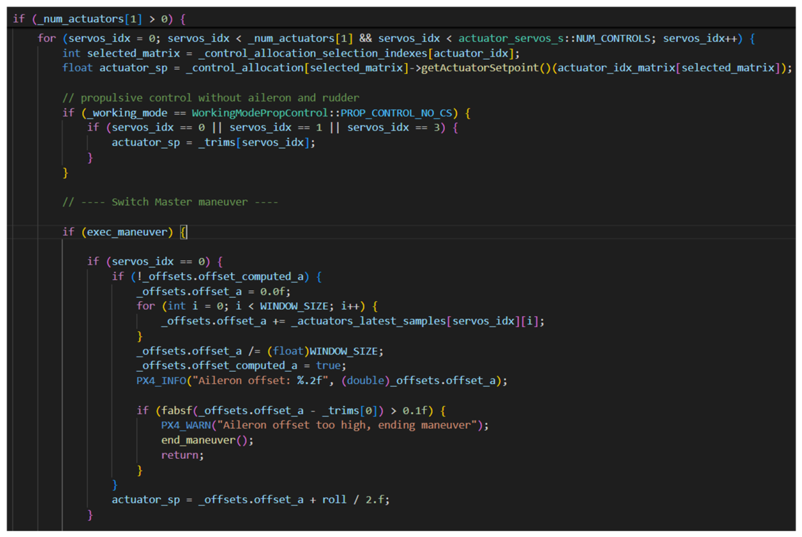
In general, if a maneuver has to be aborted, the Position Control sends a message to the Control Allocator, which interrupts it in case it is still ongoing. For the glides, instead, a message is sent to the TECS, which is responsible for the gliding logic. The Control Allocator can also prevent the maneuver initiation in case of out-of-bounds aileron or rudder trim computation. An example of a source code extract implementing this particular function is illustrated in Appendix A.2.
Lastly, the pilot can use two manual switches mapped on the remote control, one Safety Switch to override the maneuver or glide logic and go back to normal automatic flight and a standard Mode Switch to activate manual flight and regain full control, in which case maneuvers and glides are immediately aborted.
Several console messages have been implemented in PX4 to describe, during the real-time simulations, all the details related to the maneuver execution, control surfaces and motor trim computation, currently scheduled flight path angle and safety checks. In particular, warning messages colored in yellow show whether the Position Control has detected conditions for maneuver or glide abort (when the dedicated message is sent to the other modules), and whether the Control Allocator has actually aborted it, along with a message describing the reason. An example of console messages that appeared during a simulated automatic mission is shown in Figure 9. These messages are equally generated during real flight tests, but they are usually saved in the logs and then retrieved offline.
Figure 9.
PX4 console information messages and warnings during a simulated mission.
Another remarkable feature developed is the Failure Injection, which is able to simulate the failure of one or more motors. In case a motor failure is injected, the Control Allocator automatically redistributes the longitudinal thrust on the other motors, following the allocation algorithm. Instead, for thrust asymmetry compensation, one of the Individual Thrust Control (ITC) modes is activated.
The ITC is a broad set of features being developed which can be used to control the roll and yaw moments using a differential thrust commanded to the motors, together with or in place of the control surfaces. This serves to demonstrate the concept of redundancy and potential increased safety of DEP aircraft, not only due to the presence of multiple motors but also because those motors can be used to enhance or recover degraded control authority in any case of motor, control surface, servo-mechanical or other failures.
These technologies are promising and allow us to expand the use case possibilities of DEP models and increase their overall safety level, as will be discussed in forthcoming publications.
5.3. Safety Lesson from DEP-Related Dynamics
The considerations discussed in this subsection originated from the investigation of a possible contributing mechanism, but they are not intended to identify the spiral mode as a direct cause of the accident. The direct causal chain remains associated with the frozen asymmetric trim condition, ineffective maneuver interruption, and delayed restoration of manual control authority. Nevertheless, the analysis highlighted a relevant safety lesson for future DEP flight-test activities.
After the accident, the SwitchMaster was rebuilt and the testing campaign finalized. This allowed the final quantification of the stability and control derivatives of the airplane, considering the aero-propulsive interaction, in the same flight conditions of the accident, characterized by a high blowing level.
In particular, it was observed that in such conditions, the spiral mode exhibits a lower damping factor, highlighting a tendency of the system to approach instability [23] as the blowing level increases.
Although this effect was not the direct cause of the accident described in this paper, it represents an important dynamic characteristic of blown-wing DEP configurations and must be considered in the interpretation of flight-test data and in the design of safe flight-test envelopes.
These results suggest that, in DEP aircraft, the aero-propulsive interaction may not only influence steady aerodynamic coefficients such as lift and drag, but also modify the dynamic stability characteristics of the aircraft. The presence of propeller slipstream over the wing and tail surfaces alters the effective aerodynamic environment experienced by the aircraft, potentially affecting damping ratios, natural frequencies, and stability margins of the lateral–directional modes.
From a flight-test safety perspective, this observation has important implications. First, the propeller advance ratio should be considered as an additional parameter influencing the dynamic stability of the aircraft during experimental campaigns.
Second, the results highlight the importance of integrating aerodynamic modeling, system identification, and flight-test safety considerations within a unified framework. In experimental campaigns involving DEP aircraft, flight-test planning should account not only for traditional flight envelope parameters such as airspeed, altitude, and attitude, but also for aero-propulsive operating conditions that may alter the aircraft dynamic response.
Finally, the observations obtained during the SwitchMaster campaign suggest that future flight-test architectures for DEP demonstrators should incorporate model-aware safety logic, capable of adapting safety thresholds and abort criteria based on the current aero-propulsive state of the aircraft. Such an approach could improve the robustness of automated flight-test campaigns and reduce the risk associated with open-loop maneuver execution in conditions where the aircraft stability margins may be reduced.
Overall, these additional insights reinforce the need for a holistic approach to DEP flight testing, in which aerodynamic modeling, flight dynamics, control architecture, and safety barriers are considered as interconnected elements of the same experimental system.
6. Discussion and Conclusions
This paper presented the investigation of an accident involving the SwitchMaster, a distributed electric propulsion research demonstrator used for automated flight testing and system identification. The event occurred during the execution of an open-loop pitch excitation maneuver and resulted in a loss of control followed by ground impact. The reconstruction showed that the accident was generated by a combination of multiple factors rather than by a single isolated fault. The variable lateral wind, combined with lateral control surface fixation, is hypothesized to have caused the airplane to drift from its steady-flight condition.
All findings of this investigation are consistent with broader challenges in experimental aircraft flight testing and aerodynamic model identification. Flight-test maneuvers are widely used to obtain informative dynamic responses for aerodynamic modeling, and previous studies have shown that flight data can be used to identify nonlinear aerodynamic models over wide portions of the flight envelope [24,25]. At the same time, DEP demonstrators such as GL-10 and X-57 have highlighted the additional complexity introduced by distributed propulsion, closed-loop control architectures, and unconventional aero-propulsive interactions [26,27]. In this context, the SwitchMaster accident emphasizes the need for robust trim validation, immediate manual override authority, software configuration control, and independent abort criteria during automated open-loop maneuvers.
The accident discussed in this work highlights a central issue in experimental flight testing: when automation is introduced to improve repeatability and data quality, it also changes the hazard structure of the mission. In conventional manually piloted RC test activity, the pilot continuously closes the loop and compensates, at least partially, for disturbances and residual asymmetries. In the automated SwitchMaster campaign, instead, the need for clean excitation data led to an intentional temporary removal of feedback corrections during the maneuver. This created a condition in which even relatively small errors in trim estimation or logic configuration could rapidly escalate into an unrecoverable upset. Therefore, the same architecture that enabled higher-quality identification data also introduced a new and more demanding safety problem.
The structured analysis performed through the ADREP taxonomy and the Swiss Cheese Model confirmed that the accident should be interpreted as a layered systems event involving software logic, operational assumptions, procedural verification gaps, and environmental disturbance effects. This is an important result in itself, because it shows that research flight-test accidents in small demonstrators can benefit from the same disciplined safety analysis methods commonly used in broader aviation contexts.
A first point emerging from the analysis is that the transition between autopilot-controlled trim holding and open-loop maneuver execution must be considered a distinct hazard phase, not merely a technical implementation detail. In the accident flight, the aircraft was not lost during nominal autonomous path following, nor during ordinary manual piloting, but during this transition phase. The findings suggest that such phases should be protected by dedicated barrier logic, including trim plausibility checks, attitude guards, and immediate manual override authority. In other words, safety should not be evaluated only over the global mission profile, but specifically around the control-transition events that may expose the aircraft to latent unsafe states.
A second important element concerns the nature of the trim acquisition itself. In principle, the idea of computing trim values from recent actuator history is reasonable and widely used in practical test environments. However, the accident demonstrates that this method becomes unsafe if not accompanied by validation criteria. A trim state is not merely a numerical average: it is an operational assumption that the aircraft is in a physically acceptable equilibrium. If the environment is disturbed, or the aircraft is oscillating, the averaged controls may reflect the compensation of transient deviations rather than a stable underlying trim. For this reason, future implementations should verify not only the mean actuator values, but also signal dispersion, attitude stability, angular rates, and symmetry conditions before accepting the trim as valid.
The event also shows the importance of distinguishing between the existence of a safety feature and its verified availability. The maneuver kill switch was conceptually present, but functionally absent because of an unnoticed firmware-related mapping issue. This is a classic systems safety problem: latent configuration changes can silently invalidate critical protections. In research campaigns, where software and firmware are updated frequently, the probability of such latent misconfigurations is inherently higher than in mature certified environments. Consequently, pre-flight verification procedures must include explicit checks of all safety-critical channels, not only a generic confirmation that the system powers on and executes the mission logic.
Another major lesson is that manual takeover authority must dominate experimental logic at all times. The delayed restoration of control after manual mode activation was acceptable from an identification perspective, because it preserved the free-response portion of the maneuver, but it was not acceptable from a safety standpoint once an upset had already started. This paper therefore supports a clear design principle: when manual intervention is requested, any identification-related logic should be immediately overridden. In experimental flight testing, data integrity is always subordinate to flight safety and asset preservation.
More broadly, the case illustrates that lightweight research demonstrators used for advanced flight-dynamics studies occupy an intermediate space between hobby-grade RC aircraft and more formal unmanned test systems. They often lack the certification framework, redundancy, and development assurance processes of higher-end aerospace platforms, yet they may execute missions involving highly specialized automation, nonstandard control laws, and narrow safety margins. This mismatch can create a dangerous illusion of simplicity. The SwitchMaster campaign shows that once an aircraft is used as a platform for autonomous maneuver execution, system identification, and DEP-related model validation, it should be managed with a safety culture closer to that of professional flight-test operations than to that of conventional model flying.
The use of ADREP and Swiss Cheese analysis in this context also proved valuable. These frameworks helped translate a technically complex accident into an organized sequence of occurrence categories, contributing factors, failed barriers, and latent conditions. This is especially important in research environments, where accident interpretation can otherwise remain fragmented across software, flight-dynamics, and operational viewpoints. By adopting structured investigation approaches, the team was able not only to explain what happened, but also to derive corrective actions that directly informed software upgrades and procedural reforms.
Finally, the accident must also be read in light of the scientific objectives of the campaign. The broader SwitchMaster activity is devoted to studying how blowing affects aerodynamic coefficients, stability derivatives, and control characteristics. The additional technical findings suggest that some DEP operating conditions may reduce stability margins and modify modal behavior. This means that future safety architectures should become more model-aware and envelope-aware, taking into account not only classical flight parameters but also the evolving aero-propulsive condition of the aircraft. In this sense, the accident is not only a lesson in software safety or procedural rigor; it is also a reminder that research into unconventional configurations demands an equally unconventional and integrated safety methodology.
Beyond the specific case, this work provides a more general lesson for distributed electric propulsion flight testing. DEP demonstrators should not be treated as simple scaled aircraft once they are used to investigate automated maneuvers, open-loop responses, and blowing-sensitive dynamics. Their safety architecture must reflect the complexity of the physical and software interactions involved. In particular, the results suggest that future automated flight-test frameworks should integrate flight-dynamics awareness, trim plausibility assessment, control-transition protection, and stronger pilot override authority as core design principles.
Since the analysis performed in this work refers to a single accident involving a scaled remotely piloted research demonstrator, the conclusions should be interpreted in the context of experimental flight testing and cannot be directly generalized to certified or full-scale aircraft. Nevertheless, these limitations do not affect the main safety lessons identified.
In conclusion, the SwitchMaster accident represents not only a failure event to be documented, but also a valuable source of lessons learned for the development of safer automated flight-testing methodologies. The findings are relevant not only to the specific demonstrator considered here, but more broadly to experimental campaigns involving unconventional propulsion architectures, evolving control systems, and system identification in real flight conditions. More generally, the case suggests that future automated flight-testing architectures should explicitly consider control-transition phases, trim validation mechanisms, and model-aware safety barriers as fundamental elements of the flight-test system design.
Supplementary Materials
The log file generated during the flight test mission, used to realize the accident analysis, is available for download at https://doi.org/10.5281/zenodo.21441555, accessed on 1 April 2026.
Author Contributions
Conceptualization, G.F. and S.C.; Methodology, G.F. and L.T.; Software, B.M.P.; Validation, B.M.P. and N.T.; Formal analysis, G.F.; Investigation, G.F., B.M.P. and N.T.; Data curation, B.M.P.; Writing—original draft, G.F. and B.M.P.; Writing—review & editing, S.C.; Supervision, S.C., C.E.D.R. and L.T. All authors have read and agreed to the published version of the manuscript.
Funding
This research received no external funding.
Institutional Review Board Statement
Not applicable.
Informed Consent Statement
Not applicable.
Data Availability Statement
The log file generated during the flight test mission, used to realize the accident analysis, can be requested via e-mail to the corresponding author.
Acknowledgments
The authors thank Lorenzo Massa for his support in the development and testing activities, and Davide Pasquali for his role as test pilot and flight test engineer during the flight campaign.
Conflicts of Interest
The authors declare no conflicts of interest.
Abbreviations
The following abbreviations are used in this manuscript:
| ADREP | Accident/Incident Data Reporting |
| DEP | Distributed Electric Propulsion |
| FAA | Federal Aviation Administration |
| FCS | Flight Control System |
| GPS | Global Positioning System |
| ICAO | International Civil Aviation Organization |
| IMU | Inertial Measurement Unit |
| INS | Inertial Navigation System |
| ITC | Individual Thrust Control |
| MTOM | Maximum Takeoff Mass |
| PX4 | PX4 Autopilot |
| RC | Remote Control |
| TECS | Total Energy Control System |
| THA | Test Hazard Analysis |
| UAV | Unmanned Aerial Vehicle |
| UTC | Coordinated Universal Time |
Appendix A
Appendix A.1. Checklists
The checklists implemented and used for the flight operations are shown in Figure A1, divided in flight phases from assembly to disassembly, plus an emergency section.
Appendix A.2. Extract from the Improved Source Code
In the following figure, Figure A2, an extract from the improved Control Allocator module source code is presented, where the aileron trim values are computed and the input signal for maneuver execution is added. In particular, a safety check over the computed trim value is performed, which can lead to process interruption and consequent return to the pre-maneuver state.
Figure A1.
The SwitchMaster checklists for testing operations.
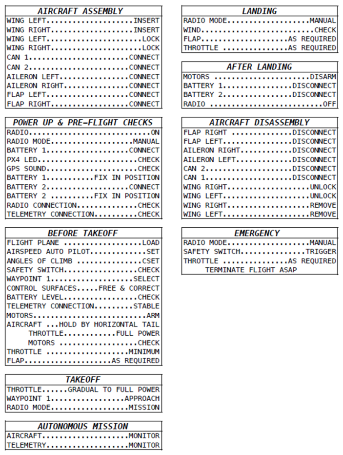
Figure A2.
Extract from the Control Allocator module source code.
Appendix B. Test Hazard Analysis Reference Framework
The reference framework for the Test Hazard Analysis performed is presented in Table A1, Table A2 and Table A3. This framework, taken from [28] and adapted to the research scope, has been used to define the level of risk for each hazard identified and the resulting mitigation procedures.
All the main hazards identified were assigned a high grade of severity and probability (from I-A to III-B), given that the reliability and redundancy level of the system under study is not comparable with that of certified commercial aircraft. In addition, the severity description of the hazards in the framework was rescaled to be compatible with the type of flight-testing activity involved in this study.
Table A1.
Hazard severity reference classification.
Table A2.
Probability reference classification.
Table A3.
Risk Index reference matrix.
References
- Kim, H.D.; Perry, A.T.; Ansell, P.J. A Review of Distributed Electric Propulsion Concepts for Air Vehicle Technology. In Proceedings of the 2018 AIAA/IEEE Electric Aircraft Technologies Symposium (EATS), Cincinnati, OH, USA, 12–13 July 2018. [Google Scholar] [CrossRef] [Scilit]
- Nicolosi, F.; Idioma, D.; Ciliberti, D.; Della Vecchia, P. Experimental Assessment of Aero-Propulsive Effects on a Commuter Aircraft due to Distributed Electric Propulsion. In Proceedings of the 10th CEAS Aerospace Europe Conference/28th AIDAA International Congress, Turin, Italy, 1–4 December 2025. [Google Scholar]
- Trainelli, L.; Riboldi, C.E.D.; Cacciola, S. Design, Implementation and Testing of a Distributed Electric Propulsion Demonstrator. In Proceedings of the 34th Society of Flight Test Engineers European Chapter Symposium, Rome, Italy, 16–18 May 2023. [Google Scholar]
- Pasquali, D.; Santeramo, A.; Alberti, L.; Tombolini, M.; Trainelli, L.; Riboldi, C.E.D. Distributed Electric Propulsion Aircraft Simulating a Single Propeller Aircraft. Patent PCT/EP2021/06217, 14 November 2016. [Google Scholar] [CrossRef] [Scilit] [PubMed]
- Cacciola, S.; Bottà, L.; Riboldi, C.E.D.; Trainelli, L. Identification of the Impact of Blowing on the Aerodynamic Model of an Airplane with Distributed Electric Propulsion. In Proceedings of the 34th ICAS Congress, Florence, Italy, 9–13 September 2024. [Google Scholar]
- Trainelli, L.; Filippoli, G.; Cacciola, S.; Riboldi, C.E.D. Flight Testing of a Distributed Electric Propulsion Demonstrator for Model Identification and Control. In Proceedings of the SFTE-EC 2025 Annual Symposium, Prague, Czech Republic, 3–6 June 2025. [Google Scholar]
- Filippoli, G.; Terzaroli, N.; Perri, B.M.; Massa, L.; Trainelli, L.; Cacciola, S.; Riboldi, C.E.D. Aero-Propulsive Modeling and System Identification of a Distributed Electric Propulsion Flying Model. In Proceedings of the 10th CEAS Aerospace Europe Conference/28th AIDAA International Congress, Turin, Italy, 1–4 December 2025. [Google Scholar]
- Kimberlin, R.D. Flight Testing of Fixed-Wing Aircraft; AIAA Education Series; American Institute of Aeronautics and Astronautics: Reston, VA, USA, 2003. [Google Scholar]
- Cacciola, S.; Filippoli, G.; Perri, B.M.; Riboldi, C.E.D.; Terzaroli, N.; Trainelli, L. Autonomous Flight Tests of a Distributed Electric Propulsion Demonstrator Based on a Total Energy Control System. In Proceedings of the 11th European Conference for Aeronautics and Aerospace Sciences (EUCASS), Rome, Italy, 30 June–4 July 2025. [Google Scholar]
- Trainelli, L.; Filippoli, G.; Terzaroli, N.; Perri, B.M.; Cacciola, S.; Riboldi, C.E.D. Automated Flight Testing of a Distributed Electric Propulsion Flying Model. In Proceedings of the 10th CEAS Aerospace Europe Conference/28th AIDAA International Congress, Turin, Italy, 1–4 December 2025. [Google Scholar]
- PX4 Documentation. Controller Diagrams. Available online: https://docs.px4.io/main/en/flight_stack/controller_diagrams#fixed-wing-position-controller (accessed on 1 April 2026).
- Filippoli, G.; Perri, B.M.; Terzaroli, N.; Trainelli, L.; Cacciola, S.; Riboldi, C.E.D. Development of an Autonomous Flight Control System for a Distributed Electric Propulsion Flying Model. In Proceedings of the 10th CEAS Aerospace Europe Conference/28th AIDAA International Congress, Turin, Italy, 1–4 December 2025. [Google Scholar]
- Lambregts, A.A. TECS Generalized Airplane Control System Design—An Update. In Proceedings of the 2013 CEAS Conference on Guidance, Navigation and Control, Delft, The Netherlands, 10–12 April 2013; Springer: Berlin/Heidelberg, Germany, 2013. [Google Scholar] [CrossRef] [Scilit]
- Stolzer, A.; Halford, C.; Goglia, J. Safety Management Systems in Aviation; Routledge: London, UK, 2016. [Google Scholar]
- Cacciabue, P.C.; Oddone, I.; Rizzolo, I. Sicurezza del Trasporto Aereo; Springer: Berlin/Heidelberg, Germany, 2019. [Google Scholar]
- International Civil Aviation Organization. Annex 13—Aircraft Accident and Incident Investigation; ICAO: Montreal, QC, Canada; Available online: https://www.icao.int/sites/default/files/postalhistory/annex_13_aircraft_accident_and_incident_investigation.htm (accessed on 1 April 2026).
- International Civil Aviation Organization. Manual of Aircraft Accident and Incident Investigation (Doc 9756); ICAO: Montreal, QC, Canada, 2020. [Google Scholar]
- Federal Aviation Administration. System Safety Handbook; FAA Office of System Safety: Washington, DC, USA, 2000.
- International Civil Aviation Organization. ADREP Taxonomy; ICAO Safety Reporting System Documentation; ICAO: Montreal, QC, Canada; Available online: https://www.icao.int/safety/AIG/taxonomy (accessed on 1 April 2026).
- Reason, J. Human Error; Cambridge University Press: Cambridge, UK, 1990. [Google Scholar]
- Reason, J. Managing the Risks of Organizational Accidents; Ashgate: Surrey, UK, 1997. [Google Scholar]
- Klein, V.; Morelli, E.A. Aircraft System Identification: Theory and Practice; American Institute of Aeronautics and Astronautics: Reston, VA, USA, 2006. [Google Scholar]
- Pamadi, B.N. Performance, Stability, Dynamics, and Control of Airplanes; American Institute of Aeronautics and Astronautics: Reston, VA, USA, 2004. [Google Scholar]
- Morelli, E.A. Efficient Global Aerodynamic Modeling from Flight Data. In Proceedings of the 50th AIAA Aerospace Sciences Meeting, Nashville, TN, USA, 9–12 January 2012. [Google Scholar]
- Brandon, J.M.; Morelli, E.A. Real-Time Onboard Global Nonlinear Aerodynamic Modeling from Flight Data. In Proceedings of the AIAA Atmospheric Flight Mechanics Conference, National Harbor, MD, USA, 13–17 June 2014. [Google Scholar]
- Fredericks, W.J.; McSwain, R.G.; Beaton, B.F.; Klassman, D.W.; Theodore, C.R. Greased Lightning (GL-10) Flight Testing Campaign; NASA Technical Memorandum NASA/TM-2017-219643; NASA: Washington, DC, USA, 2017. [Google Scholar]
- Litherland, B.L.; Borer, N.K.; Zawodny, N.S. X-57 “Maxwell” High-Lift Propeller Testing and Model Development. In Proceedings of the AIAA Aviation 2021 Forum, Virtual Event, 2–6 August 2021. [Google Scholar]
- Demsher, K.B. 412th Test Wing Test Safety Handbook; Technical Information Handbook 412TW-TIH-25-01; 412th Test Wing, Air Force Materiel Command, United States Air Force: Edwards Air Force Base, CA, USA, 2025. [Google Scholar]
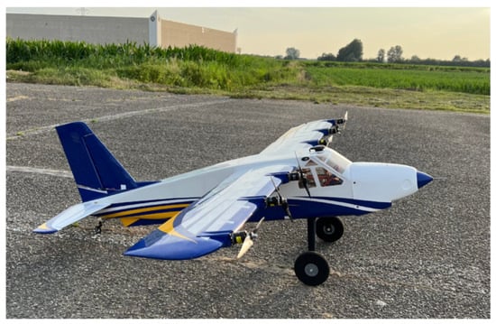
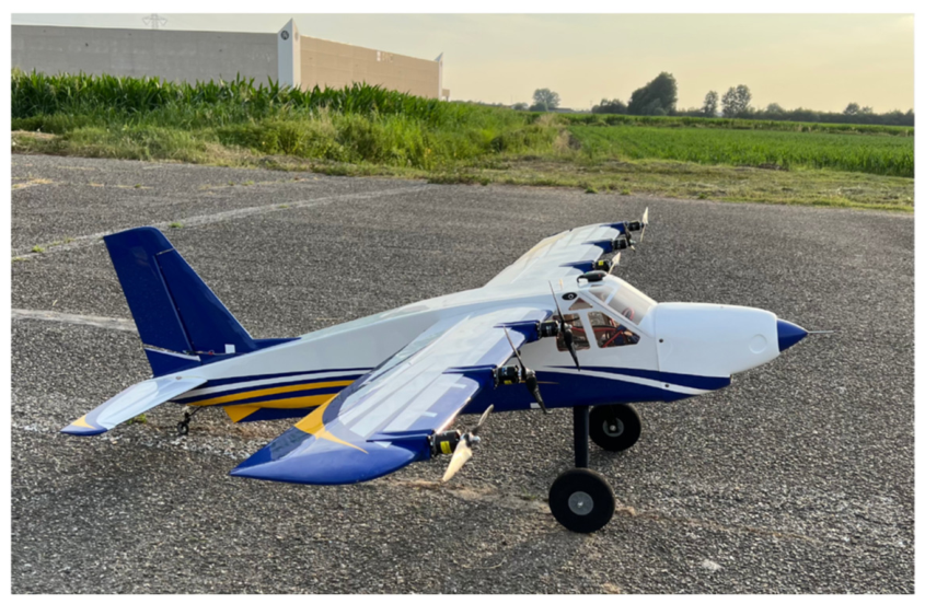
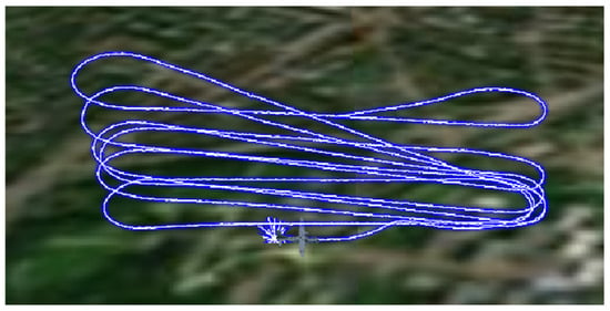
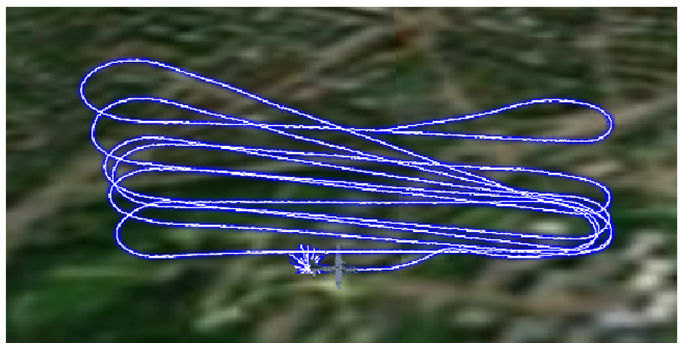
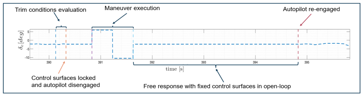
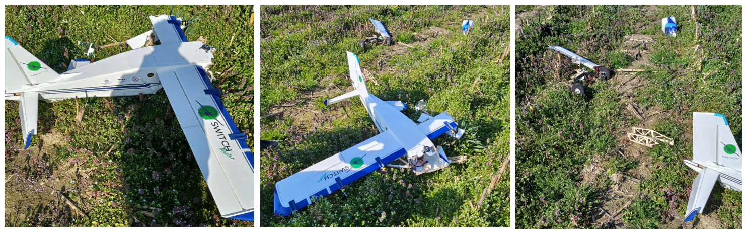
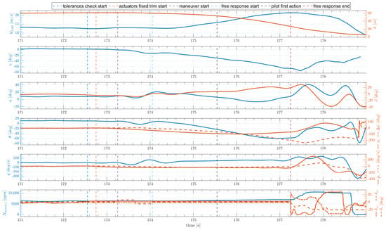
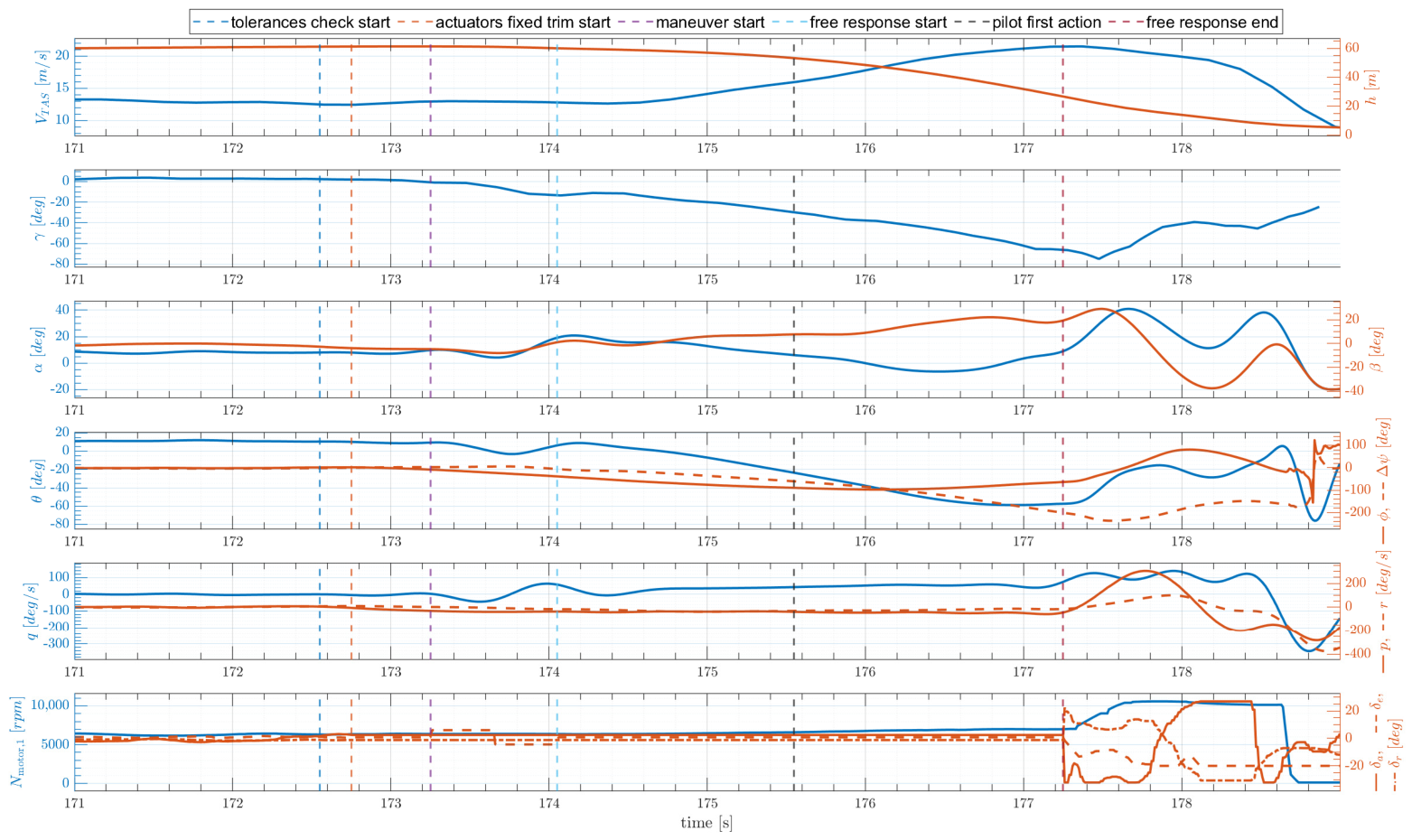
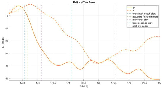
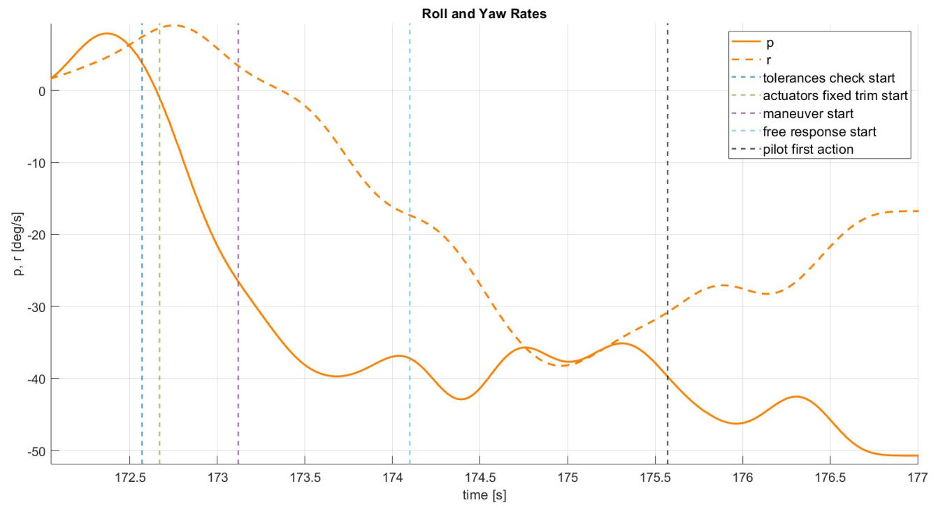
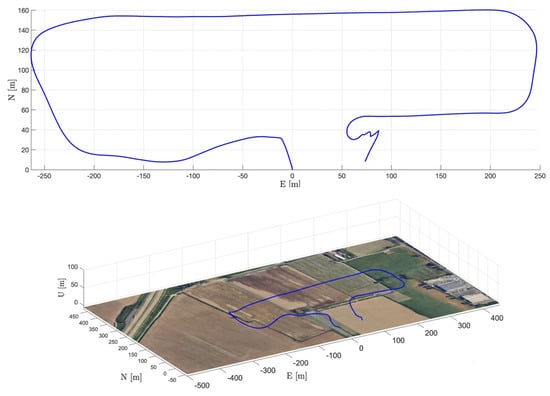
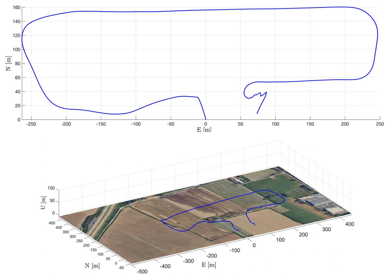
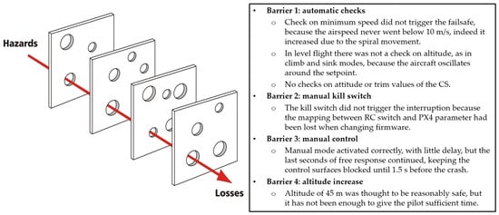
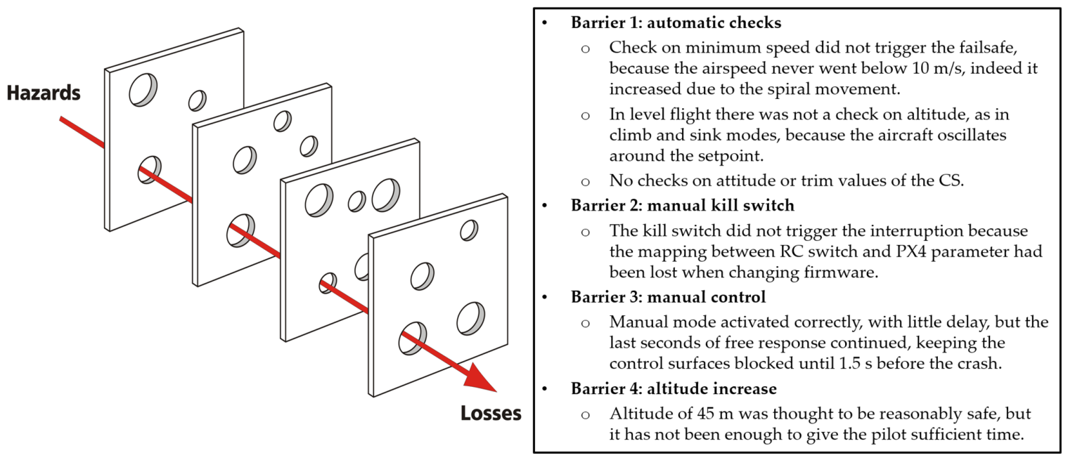
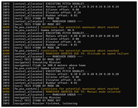
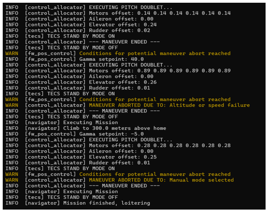

Disclaimer/Publisher’s Note: The statements, opinions and data contained in all publications are solely those of the individual author(s) and contributor(s) and not of MDPI and/or the editor(s). MDPI and/or the editor(s) disclaim responsibility for any injury to people or property resulting from any ideas, methods, instructions or products referred to in the content. |
© 2026 by the authors. Licensee MDPI, Basel, Switzerland. This article is an open access article distributed under the terms and conditions of the Creative Commons Attribution (CC BY) license.