


Abstract
Water-In-Salt (WIS) electrolytes are expected to replace expensive, environmentally harmful organic electrolytes while delivering high voltages and improving system safety. In this study, analysis of the failure modes, mechanisms, and effects of a highly concentrated potassium acetate (KAc) electrolyte was conducted through electrolyte degradation at 2 V in a conventional EDLC carbon-based symmetric configuration. The adopted method provides a simplified yet effective approach for assessing the complexity and interconnectivity of degradation mechanisms in a WIS supercapacitor. The effects analysis included electrochemical stability studies, post-mortem characterizations (SEM-EDS and XPS), low-frequency impedance fitting, and cell reassembly using end-of-life electrodes. Among the failure modes analyzed, electrolyte decomposition and pore blocking exhibit strong physicochemical correlations and high failure rates. Therefore, they should be prioritized in the design of new WIS electrolyte compositions for next-generation energy storage systems.
1. Introduction
Aqueous electrolytes are interesting because of their high ionic conductivity, non-flammability, and environmental friendliness. However, water has a relatively narrow electrochemical stability window of around 1.23 V due to its decomposition into oxygen and hydrogen at the positive and negative electrodes [1]. This limits the maximum operating voltage of batteries and supercapacitors and reduces their energy and power densities compared to organic [2] and ionic [3] liquid electrolytes. Water-In-Salt (WIS) electrolytes [4,5] have been developed to address the primary challenge of replacing expensive and environmentally harmful organic electrolytes. Highly concentrated electrolytes, or solutions with salt-to-water ratios greater than one, by both mass and volume, enable greater energy densities in electrochemical energy storage systems [6]. In WIS electrolytes, the reaction kinetics for water splitting are slower, but this also means the electrolyte conductivity is lower, which limits the system’s power output. Therefore, viscosity, conductivity, and electrochemical stability are essential parameters for designing competitive and more sustainable electrolytes for batteries and supercapacitors [7]. WIS electrolytes have been applied to symmetric and asymmetric supercapacitors [8], hybrid systems [9], and batteries [10] leading to better performance in energy density, efficiency, and cycle life. For instance, the operating voltage of an aqueous symmetric supercapacitor increased to 2.3 V by using a 17 m NaClO4/H2O electrolyte that outperformed the non-aqueous electrolytes [11]. For a battery, the operating voltage was increased by 3.2 V using a potassium acetate WIS electrolyte [10]. Among formulations currently being considered, WIS electrolytes based on potassium are attractive because potassium is an abundant element, so it is cheap [12] and it has a relatively low standard electrode potential compared with Mg, Zn, or Al.
As in any electrochemical storage system, supercapacitors are subjected to various degradation mechanisms [13] that can affect performance and longevity. The degradation mechanisms of supercapacitors are complex and interconnected, often resulting from a combination of mechanical, chemical, and thermal phenomena occurring after prolonged cycling. Electrode materials can suffer swelling and contraction [14], resulting in mechanical stresses, fracturing, and loss of active material. Operating at voltages above the electrolyte’s stability window can cause decomposition [15], leading to gas formation, pressure build-up, and pore-clogging over time [16]. Ions can become trapped in electrode pores or intercalate into the structure beyond the reversible limit, leading to a loss of capacitance and limited kinetics for high-rate performance. Aqueous electrolytes are limited to a narrow operational temperature range [17], and prolonged cycling at high currents can lead to thermal degradation [18], including evaporation and performance limitations at extreme temperatures. Additionally, the separator can degrade over time due to mechanical stress or chemical attack from electrolyte incompatibility, leading to a short circuit if the electrodes make contact [19]. For WIS electrolyte-based supercapacitors, there are reviews [4,5] that describe electrolyte stability and performance, but comprehensive studies on ageing/failure mechanisms are not yet available, to the best of our knowledge. The most critical aspects concerning WIS electrolytes are prolonged cycling and/or floating up to high voltages, which may cause water decomposition, salt precipitation, and/or porosity clogging, as presented in [13], leading to an increase in internal cell resistance and a drop in capacitance.
Given the complexity and interconnectivity of the degradation mechanisms enumerated above, the failure mode and effects analysis (FMEA) can be used to assess causes and effects, identify potential failure modes, and prioritize them by risk. The FMEA was first introduced by reliability engineers in the late 1950s and has since become an accepted method in the military and commercial sectors [20]. It provides a basis for identifying root causes of failure and developing corrective actions, and facilitates the investigation of design alternatives that consider high reliability and enhanced performance. Several government standards require the performance of an FMEA or, alternatively, the failure mode, effects, and criticality analysis (FMECA), including the MIL-STD-785, MIL-STD-1543, and NASA NHB 5300.4. These standards provide guidance on when the task is to be performed and to what depth it should be done, but they do not dictate how the analysis is to be conducted. In the context of electrochemical energy storage systems, it employs a systematic approach to identify and address potential system degradation correlated with failure modes, evaluate their effects through analysis, and classify them by risk or failure level: high, medium, and low. A risk analysis method for potential failure modes in Li-ion battery manufacturing was proposed by J. Dai et al. [21] and C. Hendricks et al. [22] developed a failure modes, mechanisms, and effects analysis (FMMEA) of Li-ion batteries, providing a generic yet detailed framework for reliability assessment and failure mechanism identification. A similar methodology was applied to the safety analysis of lithium-ion cylindrical batteries [23] and to elucidate cell-to-battery fire propagation phenomena [24].
In this work, the potassium acetate (KAc) salt concentration is first optimized with respect to electrolyte viscosity, conductivity, and stability, and then electrochemically tested as a function of voltage to evaluate system performance and ageing. Symmetric cells containing 27 m KAc-based electrolytes were degraded at 2 V, and the components disassembled for post-mortem analysis, failure mechanism identification, and risk prioritization. To our knowledge, this is the first study to develop an FMMEA of a WIS electrolyte in a carbon-based supercapacitor.
2. Materials and Methods
Self-standing electrodes were fabricated using YP-50F (99%, Kuraray, Japan) activated carbon, carbon black Super P (>99%, Alfa Aesar, Germany), and polytetrafluoroethylene, PTFE (60 wt.% dispersion in H2O, Sigma-Aldrich, USA) in the weight ratio (wt.%) 85:10:5, together with ethanol (≥99.8%, Sigma-Aldrich, UK) as the solvent for the processing. The final paste was mixed using magnetic stirring at 60 °C until ethanol evaporation, and then rolled on a glass surface until a self-standing film of about 50–60 µm was obtained. The films were dried at 110 °C in a vacuum oven for 24 h and then stored at 60 °C until use. The final electrode discs of 8–12 mm in diameter (and 1–4 mg) were used for the coin-cell assembly. Electrolytes were prepared using milli-Q ultra (18.2 MΩcm) pure water degassed with nitrogen to remove any dissolved oxygen content. Stoichiometric amounts of CH3COOK salt (≥99%, Alfa Aesar, USA) were weighted and mixed with the ultra-pure degassed water using a magnetic stirrer to obtain 1, 21, 25, 27, 30, and 32 molality (mols of the substance of solute/kg of the solvent) electrolyte concentrations. The electrolytes were sealed to prevent oxygen contamination, using a flexible cap that allowed syringe-based extraction for physicochemical and coin-cell characterizations.
Standard CR2032-type stainless steel coin cells were used for electrochemical testing and system degradation. Symmetric electrodes were used in addition to the Celgard 3501 monolayer microporous membrane (PP) or the Whatman glass microfiber GF/C separators and the above electrolytes. The electrochemical stability of the electrolytes was evaluated in a three-electrode Swagelok cell using 3 mm glassy carbon (Sigma-Aldrich) as the working electrode, oversized YP50 as the counter electrode, and Ag wire as the pseudo-reference electrode. Electrochemical tests, including cyclic voltammetry (CV), galvanostatic charge/discharge (GCD), and electrochemical impedance spectroscopy (EIS), were conducted using a VMP-3 potentiostat (Biologic, France) and a battery cycler BSC-800 (Biologic, France). EIS measurements were conducted by applying an ac voltage of 10 mV amplitude in the frequency range of 10 kHz to 10 mHz in the discharge state. The activation of the supercapacitors was carried out by performing five cyclic voltammetry (CV) cycles at a scan rate of 5 mV s−1. The procedure began with a potential of 0.5 V, which was then increased by 0.1 V per five-cycle sequence until the desired operating voltage was reached. For cell degradation, including the electrolyte, electrode, and cell components, Swagelok cells were considered since they facilitate sample recovery for post-mortem analyses.
Regarding the electrolytes’ physicochemical properties, viscosity was measured at room temperature using a Brookfield DV2T viscometer. Measurements were taken three times at ramp speeds between 0 and 200 rpm, and the averages were computed. The ionic conductivity was measured at room temperature using a Lutron CD-4309 conductivity meter. For the solid components, a Field Emission Scanning Electron Microscopy (FE-SEM) Zeiss Series Auriga 60, equipped with SE2 and In-Lens secondary electron detectors, as well as a coupled Energy Dispersive Spectroscopy (EDS) detector model INCA from Oxford Instruments, was used to study electrode particle morphology and electrode structure for the fresh and degraded samples. X-Ray Photoelectron Spectroscopy (XPS) data sets were measured using an XPS-UPS system equipped with a Analyzer hemispherical Phoibos 150 from SPECS with a mean radius of 150 mm (total energy resolution of 2.9 meV) using an X-Ray source with dual anode (Al Ka 1486.74 eV and Ag La 2984.3 eV) and a monochromator.
3. Results and Discussion
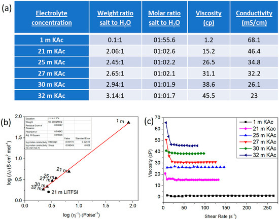
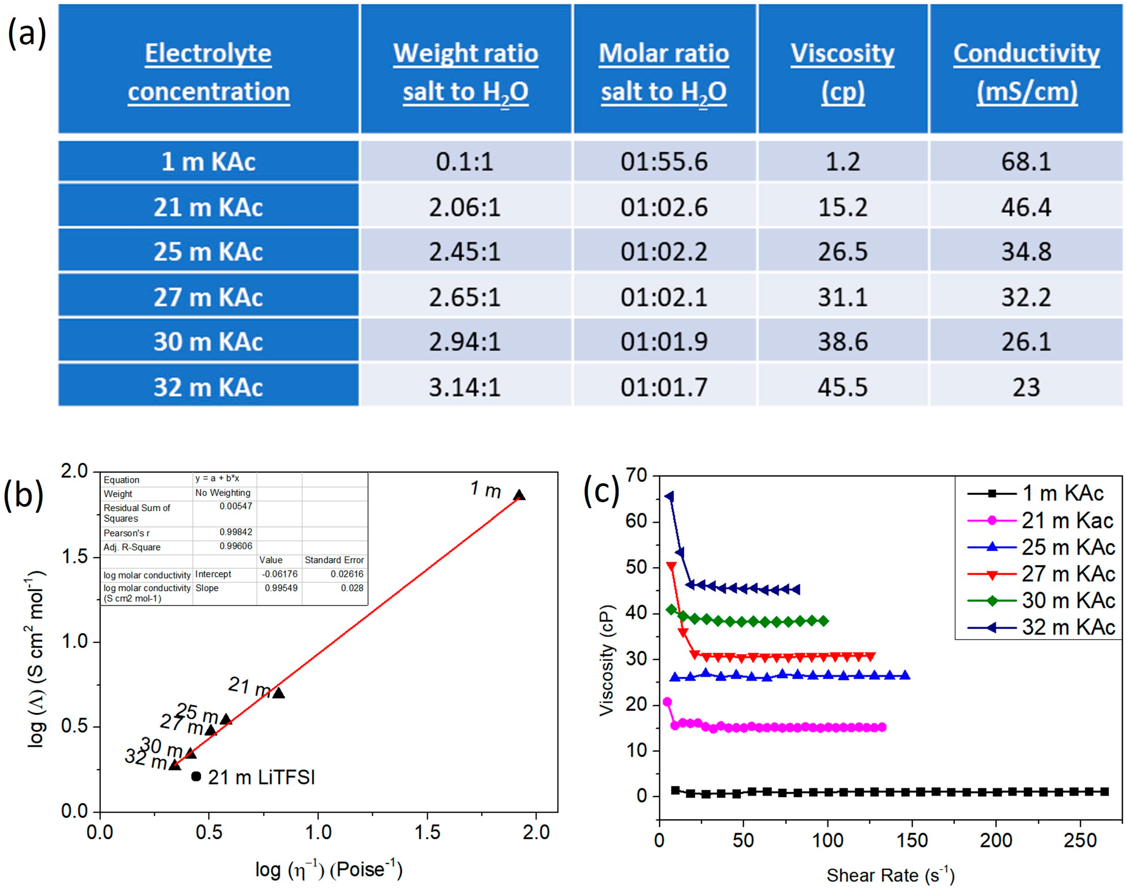
KAc-based WIS electrolytes were prepared and first characterized using viscosity and conductivity measurements. A table summarizing the main results for concentrations between 1 and 32 mol/Kg is presented in Figure 1a. Walden plot relating the molar conductivity to its viscosity and a plot of the electrolyte’s viscosity as a function of shear rate are presented in Figure 1b and Figure 1c, respectively. The ionic conductivity of electrolytes gradually decreases as the formulation changes from dilute (68.1 mS cm−1 for 1 m) to highly concentrated electrolytes (23 mS cm−1 for 32 m KAc). Viscosity behaves oppositely; it increases as the electrolyte concentration increases from 1.2 cp for 1 m KAc to 45.5 cp for 32 m KAc. At higher salt concentrations, the decrease in conductivity is mainly due to an increase in viscosity of the electrolyte, which is not compensated for by the number of charge carriers [25]. The Walden plot [26] displays a straight line indicating that the ion mobilities are strongly coupled to viscosity. Additionally, the viscosity is independent of the shear rate, indicating that the electrolytes behave like Newtonian fluids.
Figure 1.
(a) Table summarizing the conductivity and viscosity of KAc-based WIS electrolytes measured at RT; (b) Walden plot representation of molar conductivity vs. viscosity; and (c) viscosity vs. shear rate of selected electrolytes.
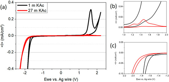
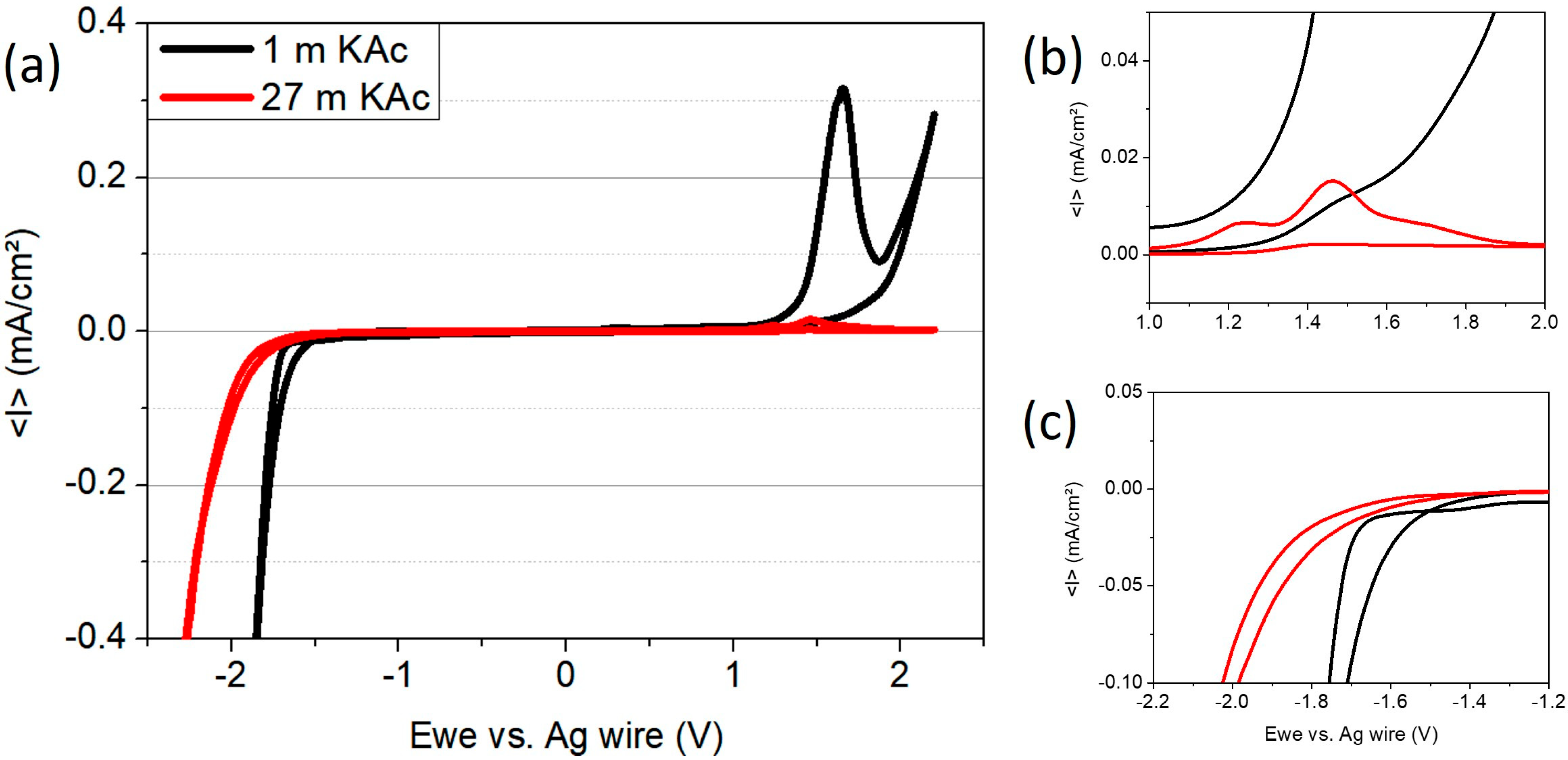
The electrochemical stability of WIS electrolytes was studied in a three-electrode cell using cyclic voltammetry (CV) with a scan rate of 0.2 mV/s. Figure 2a presents the typical cathodic and anodic scans for concentrations of 1 and 27 m KAc. Plot magnifications for the anodic and cathodic currents at selected voltages are shown in Figure 2b,c, respectively. The electrochemical stability window expands as the salt concentration increases; the cathodic current is pushed well beyond the thermodynamic stability of water, from −1.4 V to −1.7 V vs. Ag wire, and the anodic current response decreases from 0.315 mA/cm2 to 0.011 mA/cm2 at 1.4 V vs. Ag as the salt concentration increases from 1 m to 27 m KAc. Therefore, the electrochemical stability window for the WIS electrolyte is significantly larger than that of 1 m KAc: 4.1 V and 3.1 vs. Ag wire for 27 and 1 m KAc electrolytes, respectively, and this correlates very well with the fact that there are hardly any free water molecules in the 27 KAc electrolyte for oxidation or reduction, as shown in Figure 1a (molar ratio KAc:H2O). The increased stability of WIS electrolytes has been attributed to pH and to sluggish water transport at interfaces, reducing both OER and HER kinetics [15]. The cathodic current response controls the electrolyte stability window, as first observed by Tian et al. [27].
Figure 2.
Electrochemical stability window of 1 m and 27 m KAc electrolytes measured in a three-electrode cell using cyclic voltammetry (CV) with a scan rate of 0.2 mV/s; (a) overall stability vs. Ag wire; zoom-in of the (b) anodic current response, and (c) cathodic current response.
WIS electrolytes were tested in symmetric cells using self-standing YP50 electrodes fabricated with PTFE. Impedance data for the coin cells after activation are presented in the form of Nyquist plots in Figure S1a,b. The Nyquist plots display the typical shape and impedance magnitude observed for symmetrical self-standing electrodes measured in coin cells. Basically, it can be deconvoluted into an Equivalent Series Resistance (ESR), corresponding to the first Z′ intercept at high frequencies, which is between 0.5 and 3 Ω; the mid-frequency region associated with the charge transfer resistance (CTR) that corresponds to a non-ideal RC semicircle; and the low-frequency region corresponding to a straight line whose impedance is mainly imaginary. Impedance data plots considering the total cell resistance (RT) vs. electrolyte molality, and RT vs. ω−0.5 plots are presented in Figure S1c,d. The use of RT is convenient since there are no significant differences in the magnitudes of ESR and CTR among the samples. The average RT value is ~5 Ω. The plot of RT vs. ω−0.5 displays straight lines with slopes in the order of 1–10. The slope or Warburg coefficient (σ) is related to the adsorption/desorption of the active K+ and [C2H3O2]− at the electrode-electrolyte interface(s) in the symmetrical supercapacitor. Since there is no significant variation in the Warburg coefficient, the kinetics of charge storage at the interface are of the same order of magnitude.
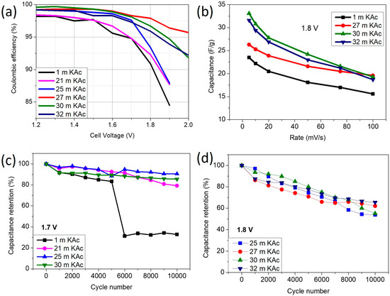
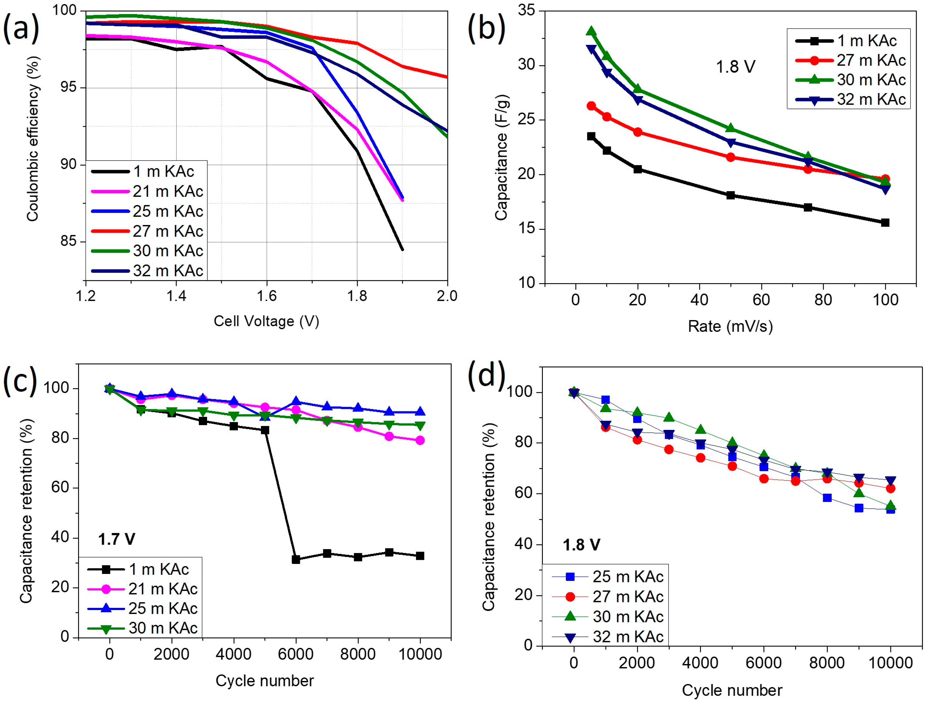
Cyclic voltammetry (CV) results for 27 m KAc in symmetric coin cells are shown in Figure S2. CVs were measured as a function of cell voltage up to 2 V at a scan rate of 50 mV/s. Within a 2 V voltage window, the recorded profile at 2 V is no ideal, indicating the presence of irreversible reactions. Electrochemical test results for the WIS electrolytes using CV analysis are shown in Figure 3. Figure 3a summarizes coulombic efficiencies calculated from the CV scans at 5 mV/s from 1.2 to 2 V. Efficiencies are greater than 95% for all electrolytes up to 1.7 V. At a higher voltage of 2 V, only 27, 30, and 32 KAc electrolytes have coulombic efficiencies greater than 90%. Figure 3b shows the specific capacitance versus rate performance at 1.8 V. The electrolytes exhibit lower capacitance at higher scan rates, decreasing from 23.2 to 15.6 F/g for the 1 m and from 26.3 to 19.6 F/g for the 27 m KAc, corresponding to capacitance retention of 67.2% and 74.5%, respectively. WIS electrolytes with concentrations 30 and 32 m KAc display a lower capacity retention of 59% as a function of scan rate, probably due to the decrease in ionic conductivity (Figure 1a). A series of 10,000 CVs at 20 mV/s was conducted to evaluate the long-term stability of the electrolyte at 1.7 V (Figure 3c) and 1.8 V (Figure 3d). Cycling results show that the retained capacitance after 10,000 cycles at 1.7 V is 90% for 25 m, 85% for 30 m, and 79% for 21 m KAc. At 1.8 V, the retained capacitance is 55% for both 25 m and 30 m, 62% for 27 m, and 65% for both 32 m and 32 m KAc.
Figure 3.
Electrochemical results obtained from CV analysis: (a) coulombic efficiencies as a function of cell voltage; (b) specific capacitance vs. scan rate from 5 to 100 mV/s at 1.8 V; (c) long-term stability at 1.7 V measured at scan rate 20 mV/s; (d) long-term stability at 1.8 V measured at scan rate 20 mV/s.
Overall, WIS electrolytes with salt concentrations of 25–32 m KAc demonstrate better performance at high operating voltages, including reduced irreversible reactions, enhanced coulombic efficiencies, higher specific capacitance, and improved stability compared to 1 m KAc. However, the electrolytes undergo degradation after 5000 cycles at 1.8 V. These results align well with previously reported performances of 1–27 m KAc at 1.7 V by J. Park et al. [28].
The degradation and failure mechanisms of the KAc WIS electrolyte-based supercapacitor were investigated using the FMMEA method. To our knowledge, no studies have addressed the identification and characterization of the main failure modes of water-in-salt electrolytes to date. Swagelok cells were also used for the degradations to facilitate sample recovery for post-mortem analyses and end-of-life component reassembly. The FMMEA method evaluated the following cell components: self-standing YP-50 electrodes, Whatman glass microfiber GF/C separator, stainless steel (SS304) or glassy carbon current collectors, and a 27 m KAc electrolyte. Results for coin cells using SS304 current collectors are presented in Figure S3a–d. To accelerate degradation, the samples were subjected to high-stress conditions via GCD at 1 A/g within a 2 V voltage window. The GCD curves for the 27 m KAc electrolyte show a distorted triangular shape with an ohmic drop (IR) of 0.35 V after activation up to 2 V (Figure S3a). As galvanostatic cycling proceeds, the ohmic drop increases (Figure S3b) in correspondence to CTR degradation (Figure S3c). From cycle 10 to 20,000 cycles, the ohmic drop increases from 0.35 V to 0.93 V, and the CTR from 25 Ω to 167 Ω. As a result, the plot of capacitance versus cycle number shows accelerated capacity decay (Figure S3d). The supercapacitor’s State-of-Health (SoH) was <50% of its total energy storage capacity (after 20,000 cycles) prior to cell dismantling for post-mortem analysis. The cell components were separated, and the positive and negative electrodes were preserved for SEM-EDS and XPS analyses.
Figures S4 and S5 show the SEM images of the fresh and degraded electrodes, respectively. The samples show no significant changes; the cycled samples retain their original structure, with no cracks, swelling, or other physical alterations. At the particle level, both negative and positive carbon materials display similar morphologies to the fresh samples; no agglomeration nor particle breaking is observed. Chemical maps, as determined by EDS analysis (Figure S6), demonstrate no chemical segregation and/or precipitation of potassium for the cycled 27 m KAC electrodes. Overall, the samples have preserved their morphological characteristics after accelerated ageing at 2 V.
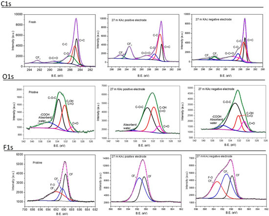
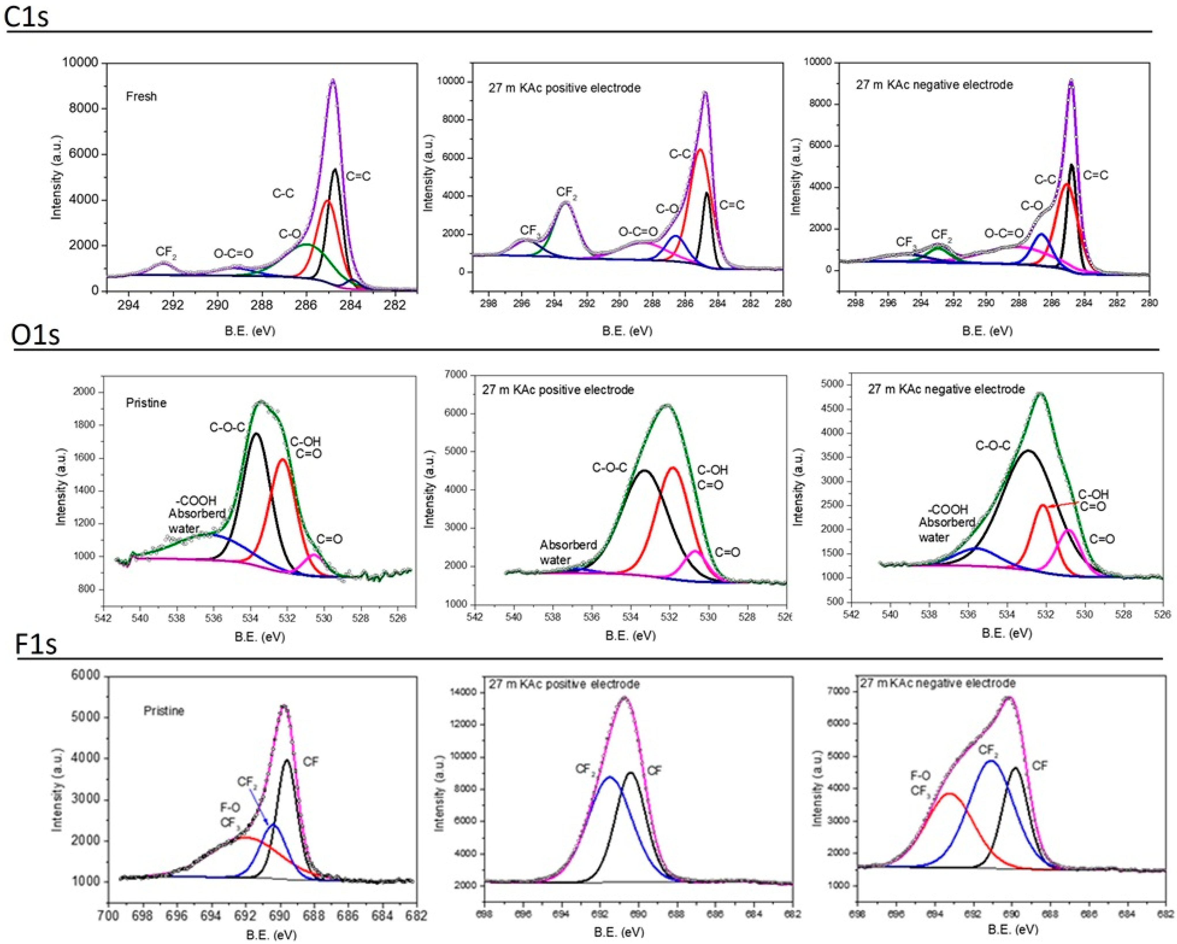
XPS was used to investigate the surface chemistry of the aged electrodes, and the results are presented in Figure 4. Given a penetration depth of approximately 10 nm, XPS is an ideal technique for identifying the elemental composition and chemical bonds of functional groups at the surface of the samples, which play an important role in the device performance [29] including durability [30]. Figure 4 shows the C1s, O1s, and F1s spectra of fresh and 27 m KAc degraded positive and negative electrodes. The fresh/pristine positive and negative electrodes were analyzed as-prepared, without exposure to the electrolyte.
Figure 4.
XPS C1s, O1s, and F1s spectra of fresh and 27 m KAc cycled positive and negative electrodes subjected to accelerated ageing via GCD at 1 A/g within a 2 V voltage window.
The deconvoluted C1s spectrum shows the characteristic PTFE corresponding to various carbon-fluorine bonding environments; CF2 and CF3 at 295–296 eV [31]. Regarding the main C=C peak, it shows broadening around 286–290 eV, mainly corresponding to an increase in the O-C=O group for the degraded samples, both positive and negative. The O1s spectra were deconvoluted using four components, including the signal of COOH, C-O-C, C-OH, and C=O [32]. The first becomes residual for the cycled samples, and the 27 m KAc negative electrode exhibits a reduction in the C-OH signal. For the XPS analysis of the F1s spectrum, the samples display significant changes in peak shape. The spectrum of the fresh sample can be deconvoluted into three peaks, ranging from the lowest to the highest energy, with CF, CF2, and CF3/F-O bonds [33]. The positive electrode cycled in 27 m KAc only needs two peaks corresponding to the CF and CF2 of the PTFE, probably due to the elimination of practically all the absorbed water and the -COOH groups observed in the O1s spectrum. The negative electrode exhibits significant peak broadening relative to the fresh and positive samples, and the CF3/F-O contribution is required to fit the spectrum.
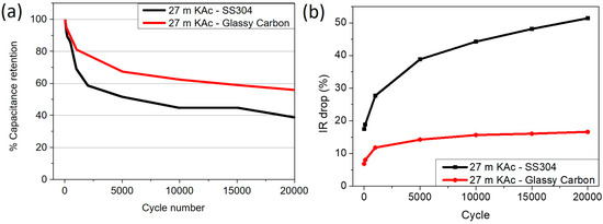
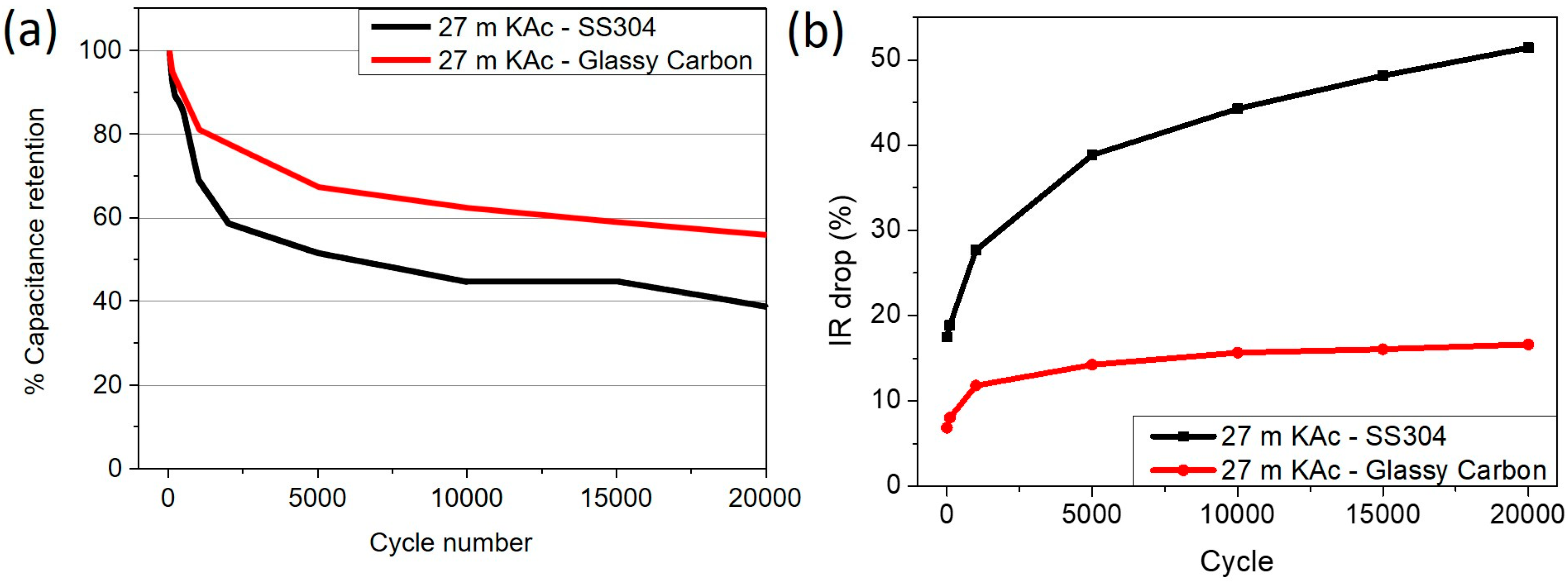
The effect of the current collector was evaluated within the FMMEA framework by assembling cells with either stainless steel (SS304) or glassy carbon current collectors. Electrochemical results are presented in Figure 5 in the form of specific capacitance and IR drop (%) vs. cycle number. The accelerated ageing process shows clear differences in the evolution of capacitance and IR drop with cycle number between the two types of current collectors. The use of SS current collectors has a detrimental effect on cell performance; capacitance rapidly decreases from 100% to ~50% after 5000 cycles, correlating with a 40% increase in IR drop. As cycling progresses, the capacitance further degrades to <80% by cycle 10,000, with an increase in IR drop of 45%. The case of glassy carbon current collectors is different and delivers a significantly improved performance. Glassy carbon is a material with high hardness, low chemical reactivity, and high electrical conductivity, which prevents the appearance of parasitic reactions that mask the faradaic and capacitive surface processes. The cell with glassy carbon current collectors exhibits a lower degradation rate and enhanced cycling stability, with SOH > 50% and an IR drop increase of <15% after 20,000 cycles.
Figure 5.
Electrochemical results in the form of (a) capacitance retention (%) and (b) IR drop (%) of the cells with either stainless steel (SS304) or glassy carbon current collectors. The other components were maintained for comparison purposes: the self-standing electrodes, the Whatman glass microfiber GF/C separator, and the 27 m KAc electrolyte. The accelerated ageing protocol via GCD at 1 A/g within a 2 V voltage window was applied after activation.
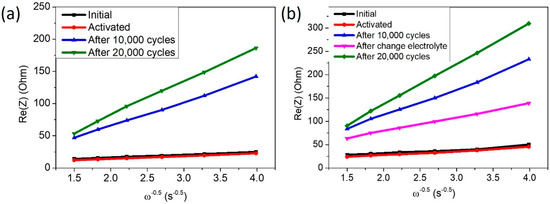
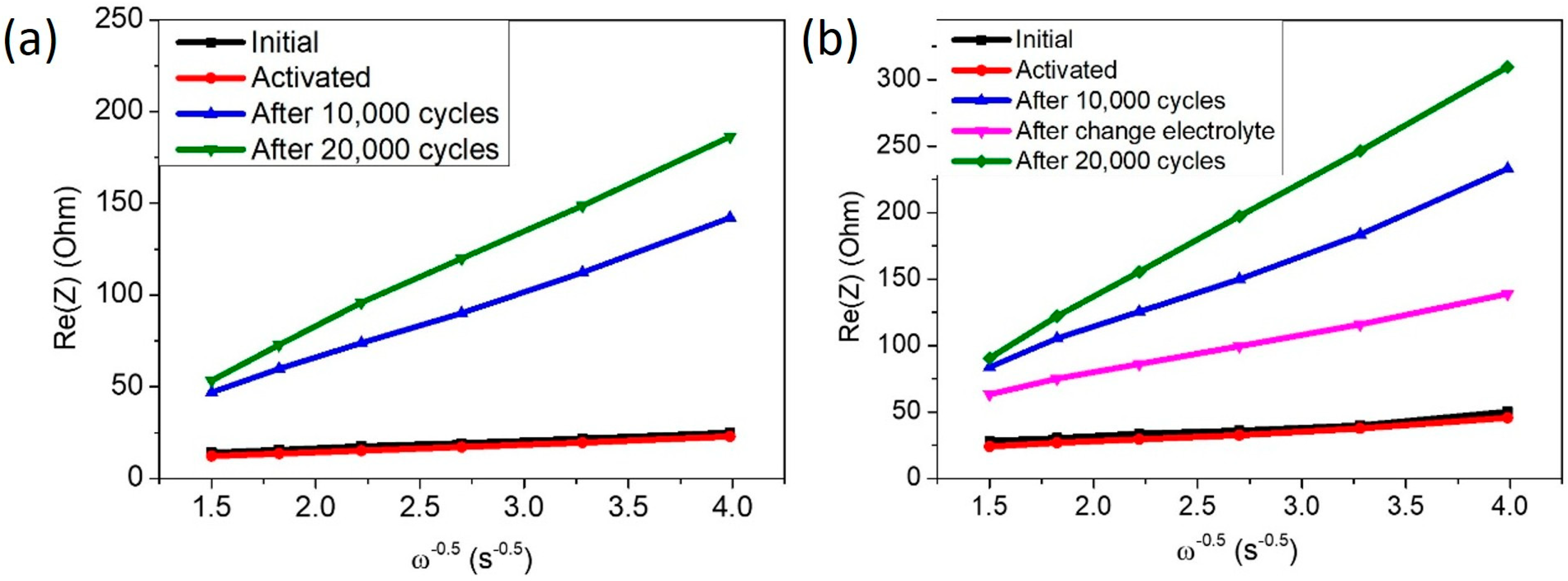
Swagelok cells equipped with glassy carbon current collectors were used to complement our electrochemical studies by reassembling cells. Basically, accelerated ageing was applied to a cell, and after 10,000 cycles, it was dismantled, electrodes recovered and washed using Milli-Q water and then reassembled using a new Whatmann separator and fresh 27 m KAc electrolyte. Following the accelerated degradation protocol previously described, EIS measurements were conducted during cell cycling and after component reassembly. The low-frequency impedance data provide information on the resistance to the absorption/desorption of the active K+ and [C2H3O2]− at the electrode-electrolyte interface(s) in a characteristic electrical-double-layer capacitive process [34,35]. The Warburg coefficient is proportional to the inverse of the square root of ion diffusion. The smaller Warburg slope indicates lower resistance to ion transport to the pores. Figure 6 shows Re vs. ω−0.5 plots for (a) the reference Swagelok cell, and (b) the reassembled Swagelok cell. In Figure 6a, the Warburg slope is small ~4 for the fresh and after activation, and it increases to ~35 and eventually to ~60 as a function of cycling, 10,000 and 20,000 cycles, respectively. The increase in the Warburg coefficient is associated with an increased resistance to ion absorption/desorption at the electrode pore level. However, if the cell is dismantled after 10,000 cycles and the washed electrode is reassembled using fresh electrolyte, a smaller Warburg coefficient (Figure 6b, pink trace) and a higher specific capacitance (Figure S7) are obtained. This indicates that the ions partially recover access to the pores after cell reassembly. The improvement in diffusivity could not be maintained beyond 20,000 cycles, as the Warburg coefficient increased (green trace in Figure 6b) and the system capacitance degraded (Figure S7).
Figure 6.
Plot of the real impedance part Re vs. ω−0.5 of (a) the reference Swagelok cell, (b) the reassembled Swagelok cell: cycled to 10,000 cycles, dismantled and reassembled, and then cycled 10,000 cycles more. The cell components were self-standing YP-50 electrodes, a Whatman glass microfiber GF/C separator, and a 27 m KAc electrolyte, all supported by glass carbon current collectors. The accelerated ageing protocol was GCD at 1 A/g and 2 V.
Overall, the FMMEA method was applied to a potassium acetate water-in-salt electrolyte-based supercapacitor to evaluate failure modes and associated mechanisms, and to conduct local and system-effect analyses via electrochemical and post-mortem analyses, including SEM, XPS, and cell reassembly, to determine the failure level (low, medium, or high) for risk prioritization. Table 1 summarizes the FMMEA results obtained after applying an accelerated ageing protocol consisting of GCD cycles at 1 A/g and 2 V in ambient, room temperature conditions.
Table 1.
Failure modes, mechanisms, and effects analysis (FMMEA) of a potassium acetate (KAc) water-in-salt electrolyte-based supercapacitor.
The electrode structure can undergo swelling and contraction [14], including mechanical degradation of the carbon and binder due to prolonged cycling or peak power demands, reducing the system-specific capacitance and increasing the charge-transfer resistance, and ultimately leading to a shorter cycle life. The SEM-EDS analysis demonstrated that the cycled samples retained their original structure, with no cracks, swelling, or other physical alterations at both particle and electrode levels after accelerated ageing. Therefore, a low failure level is assigned to the electrode’s mechanical degradation.
Pore blocking is a failure mode that affects carbon electrodes [36]. It can occur via the reaction of YP-50F with oxygen generated by electrolyte decomposition or oxygen gas evolution (OER) at the positive electrode [37]. The system’s operating voltage determines this failure mode. The generation of CO2, CO, O2, and H2, along with solid decomposition products and passivation layers [38] leads to pore blockage, thereby degrading supercapacitor performance. The XPS analysis revealed an increase in oxygen-containing functional groups in the cycled electrodes. Additionally, it was demonstrated that if the supercapacitor is dismantled after 10,000 cycles and the washed electrodes are reassembled with fresh electrolyte, ionic access to the pores and the system-specific capacitance substantially recover. A high failure level was assigned to pore blocking.
The WIS electrolyte decomposes primarily into hydrogen gas at the anode, oxygen gas at the cathode, and various salt-derived degradation products when the operational voltage exceeds its stability window. Water-in-salt electrolytes are expected to minimize water splitting [15], thereby enhancing energy storage by pushing the system’s voltage limits. However, electrochemical stability studies conducted in 3-electrode cells demonstrated residual parasitic currents even at a high salt concentration of 27 mM KAc, which increased system pressure and promoted pore blocking, ultimately leading to system degradation and failure. Therefore, a high failure level is assigned to electrolyte decomposition.
Corrosion of the current collector(s) is also a primary failure in energy storage systems [39]. It depends mainly on the materials and their reactivity with the liquid electrolyte. For highly corrosive interfaces in aqueous media, e.g., Al, passivation layers are required to improve internal cell conductivity while minimizing the formation of inactive insulating phases at the interphases [40]. Using Swagelok cells, in which components are readily interchangeable, two types of current collectors were considered: 304 stainless steel and glassy carbon. Electrochemical results demonstrate that glassy carbon-supported cells exhibit a significantly lower degradation rate, resulting in an enhanced cycle life under accelerated ageing conditions. A medium failure level is assumed for the corrosion of the current collector(s).
A short circuit in an energy storage system is considered the worst-case failure mode. This failure mode is associated with mechanical alteration, shrinkage, or the formation of holes/cracks, usually at high temperature [41]. This would place the positive and negative electrodes in direct contact, resulting in rapid electron flow and a strong electric discharge between the plates. A low failure probability is assigned to the separator fracture because any short-circuit sample response was observed during system degradation at room temperature.
4. Conclusions
WIS electrolytes are interesting because they enable higher energy densities than conventional aqueous electrolytes, which are limited by water-splitting reactions. In this paper, the physicochemical, electrical, and electrochemical properties of highly concentrated potassium acetate (KAc) electrolytes for high-voltage applications. Among the compositions evaluated, the 27 m KAc was selected for failure modes, mechanisms, and effects analysis since it demonstrates better electrochemical stability and electrochemical performance in terms of coulombic efficiency, specific capacitance, and improved cyclability as a function of rate and voltage (up to 1.8 V) with respect to a 1m KAc-based electrolyte.
The 27 m KAc WIS electrolyte-based supercapacitor was subjected to accelerated ageing using galvanostatic charge/discharge at 1 A/g and 2 V in ambient, room-temperature conditions, and the components recovered, analyzed, and reassembled to assess failure modes, mechanisms, and causes, while prioritizing them by failure risk level: high, medium, and low. The use of the FMMEA provided a simplified yet effective methodology for assessing the complexity and interconnectivity of the degradation mechanisms in the WIS supercapacitor. The method identified five failure modes: electrode degradation, pore blocking, electrolyte decomposition, corrosion of the current collector(s), and separator shrinkage/fracture, through material and system analyses, including electrochemical stability studies, post-mortem characterizations (SEM-EDS and XPS), low-frequency impedance fitting, and cell reassembly. Among the modes analyzed, pore blocking and electrolyte decomposition are considered to have high failure rates. These two failure modes are interconnected because parasitic chemical reactions lead to gas evolution, material passivation, and, ultimately, pore blockage. This was reversed by reassembling washed electrodes in a fresh water-in-salt electrolyte using Swagelok cells: the system significantly recovered its performance, including pore access and specific capacitance.
Overall, although water-in-salt electrolytes are engineered to mitigate water-splitting reactions and thereby maximize the system’s energy density by increasing the operational voltage window, the primary failure modes arise from the electrolyte’s stability window and from interactions between decomposition reaction products and the carbon electrode.
Supplementary Materials
The following supporting information can be downloaded at: https://www.mdpi.com/article/10.3390/batteries12040111/s1. Figure S1: Impedance data plots of coin cells containing WIS electrolytes (1, 21, 25, 27, 30, and 32 m KAc); (a) Nyquist plots measured after cell activation; (b) zoom-in of the charge transfer resistance; (c) RT vs. electrolyte molality (KAc); (d) RT vs. ω-0.5; Figure S2: Typical CV plot of a highly concentrated WIS electrolyte, i.e., 27 m KAc, measured in a symmetric coin-cell; Figure S3: Accelerated ageing of 27 m KAc WIS electrolyte at 1 A/g within a 2 V voltage window; (a) GCD plot after activation; (b) IR drop and (c) CTR evolution as a function of cycling, and (d) long-term electrolyte stability in a symmetric coin-cell configuration (standard KOH electrolyte is added for comparison); Figure S4: SEM pictures of carbon components of the self-standing electrode; (a,b) YP50 activated carbon; (c) Super P conductive carbon; (d) fresh self-standing electrode of YP50: SuperP: PTFE with 85:10:5 wt.%; Figure S5: SEM pictures of degraded YP50 electrodes, positive and negative, in a symmetric cell using 27 m KAc liquid electrolyte for 20,000 cycles at 1 A/g in the voltage window 0–2 V. Different magnifications (3 K and 5 K, 20 K, 50 K) for both electrodes are shown; Figure S6: EDS analysis for the cycled YP50 electrodes in 27 m KAc electrolyte, positive and negative, respectively; Figure S7: Capacitance retention of reference Swagelock cell (red trace) and reassembled Swagelok cell (black trace). The cell components were self-standing YP-50 electrodes, a Whatman glass microfiber GF/C separator, and a 27 m KAc electrolyte, all supported by glass carbon current collectors. The accelerated ageing protocol was GCD at 1 A/g and 2 V.
Author Contributions
Conceptualization, J.M.D.; Methodology, J.M.D.; Formal analysis, J.M.D. and J.J.B.; Investigation, J.M.D. and J.J.B.; Resources, J.J.B. and J.M.D.; Writing—original draft, J.J.B.; Writing—review & editing, J.J.B.; Visualization, J.J.B.; Supervision, J.R.M. and J.J.B.; Project administration, J.J.B.; Funding acquisition, J.J.B. All authors have read and agreed to the published version of the manuscript.
Funding
This research received no external funding.
Data Availability Statement
The original contributions presented in this study are included in the article/Supplementary Materials. Further inquiries can be directed to the corresponding author(s).
Acknowledgments
Jordi Jacas Biendicho acknowledges the fellowship RYC2021–034994-I, funded by MICIU/AEI/10.13039/501100011033 and the European Union «NextGenerationEU/PRTR».
Conflicts of Interest
The authors declare no conflict of interest.
References
- Zang, X.; Shen, C.; Sanghadasa, M.; Lin, L. High-Voltage Supercapacitors Based on Aqueous Electrolytes. ChemElectroChem 2019, 6, 976–988. [Google Scholar] [CrossRef] [Scilit]
- Acharjee, A.; Saha, B. Organic electrolytes in electrochemical supercapacitors: Applications and developments. J. Mol. Liq. 2024, 400, 124487. [Google Scholar] [CrossRef] [Scilit]
- Wang, Y.; Xue, K.; Yan, C.; Li, Y.; Zhang, X.; Su, K.; Ma, P.; Wan, S.; Lang, J. Tuning of Ionic Liquid–Solvent Electrolytes for High-Voltage Electrochemical Double Layer Capacitors: A Review. Batteries 2024, 10, 54. [Google Scholar]
- Suo, L.; Borodin, O.; Gao, T.; Olguin, M.; Ho, J.; Fan, X.; Luo, C.; Wang, C.; Xu, K. “Water-in-salt” electrolyte enables high-voltage aqueous lithium-ion chemistries. Science 2015, 350, 938–943. [Google Scholar]
- Lannelongue, P.; Bouchal, R.; Mourad, E.; Bodin, C.; Olarte, M.; le Vot, S.; Favier, F.; Fontaine, O. “Water-in-Salt” for Supercapacitors: A Compromise between Voltage, Power Density, Energy Density and Stability. J. Electrochem. Soc. 2018, 165, A657–A663. [Google Scholar] [CrossRef] [Scilit]
- Mishra, R.N.; Madikere Raghunatha Reddy, A.K.; Goulet, M.A.; Zaghib, K. Water-in-Salt Electrolytes: Advances and Chemistry for Sustainable Aqueous Monovalent-Metal-Ion Batteries. Batteries 2025, 11, 120. [Google Scholar] [CrossRef] [Scilit]
- Liang, T.; Hou, R.; Dou, Q.; Zhang, H.; Yan, X. The Applications of Water-in-Salt Electrolytes in Electrochemical Energy Storage Devices. Adv. Funct. Mater. 2021, 31, 2006476. [Google Scholar]
- Avireddy, H.; Byles, B.W.; Pinto, D.; Miguel, J.; Galindo, D.; Jacas, J.; Wang, X.; Flox, C.; Crosnier, O.; Brousse, T.; et al. Nano Energy Stable high-voltage aqueous pseudocapacitive energy storage device with slow self-discharge. Nano Energy 2019, 64, 103961. [Google Scholar]
- Deng, W.; Wang, X.; Liu, C.; Li, C.; Chen, J.; Zhu, N.; Li, R.; Xue, M. Li/K mixed superconcentrated aqueous electrolyte enables high-performance hybrid aqueous supercapacitors. Energy Storage Mater. 2019, 20, 373–379. [Google Scholar] [CrossRef] [Scilit]
- Leonard, D.P.; Wei, Z.; Chen, G.; Du, F.; Ji, X. Water-in-Salt Electrolyte for Potassium-Ion Batteries. ACS Energy Lett. 2018, 3, 373–374. [Google Scholar] [CrossRef] [Scilit]
- Bu, X.; Su, L.; Dou, Q.; Lei, S.; Yan, X. A low-cost “water-in-salt” electrolyte for a 2.3 V high-rate carbon-based supercapacitor. J. Mater. Chem. A Mater. 2019, 7, 7541–7547. [Google Scholar] [CrossRef] [Scilit]
- Vedhanarayanan, B.; Seetha Lakshmi, K.C. Beyond lithium-ion: Emerging frontiers in next-generation battery technologies. Front. Batter. Electrochem. 2024, 3, 1377192. [Google Scholar]
- Pameté, E.; Köps, L.; Kreth, F.A.; Pohlmann, S.; Varzi, A.; Brousse, T.; Balducci, A.; Presser, V. The Many Deaths of Supercapacitors: Degradation, Aging, and Performance Fading. Adv. Energy Mater. 2023, 13, 2301008. [Google Scholar] [CrossRef] [Scilit]
- Menzel, J.; Slesinski, A.; Galek, P.; Bujewska, P.; Kachmar, A.; Frąckowiak, E.; Washio, A.; Yamamoto, H.; Ishikawa, M.; Fic, K. Operando monitoring of activated carbon electrodes operating with aqueous electrolytes. Energy Storage Mater. 2022, 49, 518–528. [Google Scholar] [CrossRef] [Scilit]
- Gomez Vazquez, D.; Ingenmey, J.; Trapp, K.; Ciliak, D.; Salanne, M.; Lukatskaya, M.R. Extended Stability Window in Water-in-Salt Electrolytes: Understanding the Origins. J. Am. Chem. Soc. 2025, 147, 35953–35961. [Google Scholar]
- Phadke, S.; Amara, S.; Anouti, M. Gas Evolution in Activated-Carbon-Based Supercapacitors with Protic Deep Eutectic Solvent as Electrolyte. ChemPhysChem 2017, 18, 2364–2373. [Google Scholar] [CrossRef] [Scilit]
- Omori, T.; Nakanishi, M.; Tashima, D. High-temperature degradation tests on electric double-layer capacitors: The effect of residual voltage on degradation. Materials 2021, 14, 1520. [Google Scholar] [CrossRef] [Scilit]
- Mazloomian, K.; Dore, T.R.; Buckwell, M.; Bird, L.; Shearing, P.R.; Miller, T.S. Supercapacitor safety: Temperature driven instability and failure of electrochemical double layer capacitors. Energy Storage Mater. 2025, 76, 104115. [Google Scholar] [CrossRef] [Scilit]
- Yuan, C.; Wang, L.; Yin, S.; Xu, J. Generalized separator failure criteria for internal short circuit of lithium-ion battery. J. Power Sources 2020, 467. [Google Scholar] [CrossRef] [Scilit]
- Borgovini, R.; Pemberton, S.; Rossi, M. Failure Mode, Effects and Criticality Analysis (FMECA). 1993. Available online: https://s3vi.ndc.nasa.gov/ssri-kb/static/resources/a278508.pdf (accessed on 20 February 2026).
- Dai, J.; Pang, J. A risk analysis method for potential failure modes in the lithium-ion battery assembly process based on optimized FMEA and DHHFLTS. Sci. Rep. 2025, 15, 28327. [Google Scholar] [CrossRef] [Scilit]
- Hendricks, C.; Williard, N.; Mathew, S.; Pecht, M. A failure modes, mechanisms, and effects analysis (FMMEA) of lithium-ion batteries. J. Power Sources 2015, 297, 113–120. [Google Scholar] [CrossRef] [Scilit]
- Maddipatla, S.; Kong, L.; Pecht, M. Safety Analysis of Lithium-Ion Cylindrical Batteries Using Design and Process Failure Mode and Effect Analysis. Batteries 2024, 10, 76. [Google Scholar] [CrossRef] [Scilit]
- Held, M.; Brönnimann, R. Safe cell, safe battery? Battery fire investigation using FMEA, FTA and practical experiments. Microelectron. Reliab. 2016, 64, 705–710. [Google Scholar] [CrossRef] [Scilit]
- Abu-Lebdeh, Y.; Davidson, I. High-Voltage Electrolytes Based on Adiponitrile for Li-Ion Batteries. J. Electrochem. Soc. 2009, 156, A60. [Google Scholar] [CrossRef] [Scilit]
- Xu, W.; Cooper, E.I.; Angell, C.A. Ionic liquids: Ion mobilities, glass temperatures, and fragilities. J. Phys. Chem. B 2003, 107, 6170–6178. [Google Scholar] [CrossRef] [Scilit]
- Tian, Z.; Deng, W.; Wang, X.; Liu, C.; Li, C.; Chen, J.; Xue, M.; Li, R.; Pan, F. Superconcentrated aqueous electrolyte to enhance energy density for advanced supercapacitors. Funct. Mater. Lett. 2017, 10, 1750081. [Google Scholar] [CrossRef] [Scilit]
- Park, J.; Kim, J.; Lee, S.; Kim, J.H.; Yoon, M.H.; Lee, D.; Yoo, S.J. Unraveling concentration-dependent solvation structures and molecular interactions in water-in-salt electrolytes for enhanced performance of electric double-layer capacitors. Energy Storage Mater. 2024, 65, 103137. [Google Scholar] [CrossRef] [Scilit]
- Qiu, C.; Jiang, L.; Gao, Y.; Sheng, L. Effects of oxygen-containing functional groups on carbon materials in supercapacitors: A review. Mater. Des. 2023, 230, 111952. [Google Scholar] [CrossRef] [Scilit]
- Yang, C.H.; Nguyen, Q.D.; Chen, T.H.; Helal, A.S.; Li, J.; Chang, J.K. Functional Group-Dependent Supercapacitive and Aging Properties of Activated Carbon Electrodes in Organic Electrolyte. ACS Sustain. Chem. Eng. 2018, 6, 1208–1214. [Google Scholar] [CrossRef] [Scilit]
- Asrafali, S.P.; Periyasamy, T.; Kim, S.C.; Lee, J.W. Enhanced Wettability and Adhesive Property of PTFE Through Surface Modification with Fluorinated Compounds. Materials 2024, 17, 3051. [Google Scholar] [CrossRef] [Scilit]
- Pletincx, S.; Trotochaud, L.; Fockaert, L.L.; Mol, J.M.C.; Head, A.R.; Karslloǧlu, O.; Bluhm, H.; Terryn, H.; Hauffman, T. In situ characterization of the initial effect of water on molecular interactions at the interface of organic/inorganic hybrid systems. Sci. Rep. 2017, 7, srep45123. [Google Scholar] [CrossRef] [Scilit]
- Wijaya, O.; Hartmann, P.; Younesi, R.; Markovits, I.I.E.; Rinaldi, A.; Janek, J.; Yazami, R. A gamma fluorinated ether as an additive for enhanced oxygen activity in Li-O2 batteries. J. Mater. Chem. A Mater. 2015, 3, 19061–19067. [Google Scholar] [CrossRef] [Scilit]
- Azizpour, A.; Bagovic, N.; Ploumis, N.; Mylonas, K.; Hoxha, D.; Kienberger, F.; Al-Zubaidi-R-Smith, N.; Gramse, G. Electrochemical Analysis of Carbon-Based Supercapacitors Using Finite Element Modeling and Impedance Spectroscopy. Energies 2025, 18, 1450. [Google Scholar] [CrossRef] [Scilit]
- Hakamy, A. Investigation of double-layer capacitance, Warburg finite-length impedance and AC conductivity of PVA/MWCNT nanocomposite films for supercapacitor applications. J. Power Sources 2025, 656, 238032. [Google Scholar]
- Chen, X.; Wu, Y.; Holze, R. Ag(e)ing and Degradation of Supercapacitors: Causes, Mechanisms, Models and Countermeasures. Molecules 2023, 28, 5028. [Google Scholar] [CrossRef] [Scilit] [PubMed]
- Hahn, M.; Würsig, A.; Gallay, R.; Novák, P.; Kötz, R. Gas evolution in activated carbon/propylene carbonate based double-layer capacitors. Electrochem. Commun. 2005, 7, 925–930. [Google Scholar] [CrossRef] [Scilit]
- Hema, R.K.; Varzi, A. Aqueous Solid Electrolyte Interphases in Water-in-Salt Electrolytes and Beyond. ChemElectroChem 2025, 12, e202500129. [Google Scholar] [CrossRef] [Scilit]
- Gabryelczyk, A.; Ivanov, S.; Bund, A.; Lota, G. Corrosion of aluminium current collector in lithium-ion batteries: A review. J. Energy Storage 2021, 43, 103226. [Google Scholar] [CrossRef] [Scilit]
- Chomkhuntod, P.; Iamprasertkun, P.; Chiochan, P.; Suktha, P.; Sawangphruk, M. Scalable 18,650 aqueous-based supercapacitors using hydrophobicity concept of anti-corrosion graphite passivation layer. Sci. Rep. 2021, 11, 13082. [Google Scholar] [CrossRef] [Scilit]
- Li, H.; Li, J.; Zhao, C.; Zhao, F. Research on the Preparation of Supercapacitor Separators with High Wettability and Excellent Temperature Adaptability Through In Situ Deposition of Nano-Barium Sulfate on Regenerated Cellulose. Polymers 2025, 17, 842. [Google Scholar] [CrossRef] [Scilit]

Disclaimer/Publisher’s Note: The statements, opinions and data contained in all publications are solely those of the individual author(s) and contributor(s) and not of MDPI and/or the editor(s). MDPI and/or the editor(s) disclaim responsibility for any injury to people or property resulting from any ideas, methods, instructions or products referred to in the content. |
© 2026 by the authors. Licensee MDPI, Basel, Switzerland. This article is an open access article distributed under the terms and conditions of the Creative Commons Attribution (CC BY) license.