


Abstract
High-energy-density Li-ion batteries demand highly graphitized graphite anodes, yet elevated graphitization inevitably amplifies structural anisotropy, obstructing Li+ intercalation and compromising rate capability. To resolve this trilemma, we establish a precursor–structure–performance framework for pitch-based artificial graphites, revealing that this performance trade-off is governed by impurity content, ordered domains, and micropores: low-impurity precursors facilitate crystallite growth along the c-axis to realize high graphitization; ordered domains promote in-plane crystallite growth; and intrinsic micropores restrain excessive in-plane crystallite enlargement, lowering the orientation index and maintaining structural isotropy. Purified coal-based needle coke emerges as the optimal matrix, featuring a high graphitization degree of 94.89% alongside a moderate orientation index of 10.25. A resin-derived hard-carbon coating, with markedly higher disorder than its pitch-derived counterpart, is applied to construct an isotropic core–shell architecture (AG-R). The disordered surface layer acts as a Li+ transfer station, preserving low-rate capacity while boosting the Li+ diffusion coefficient by ~2.2-fold. In 2.5 Ah 18,650 full cells, AG-R achieves an energy density exceeding 430 Wh kg−1 (based on the total active material mass), retains 92.3% capacity at 10 C discharge and 81.6% at 3 C charge, and sustains over 80% capacity retention after 4600 cycles at 1 C. This work validates that precursor-directed bulk isotropy regulation, coupled with surface disordering engineering, offers a viable pathway toward fast-charging, high-energy graphite anodes.
1. Introduction
Carbonaceous anode materials, particularly pitch-derived artificial graphite, have long dominated the commercial Li-ion battery industry as the preferred anode for Li-ion batteries (LIBs), owing to their high theoretical lithium-storage capacity (372 mAh g−1) and moderate volume expansion (~10%) upon lithiation [1,2]. Nevertheless, the growing market demand for next-generation high-performance LIBs has exposed intrinsic bottlenecks in simultaneously achieving high-energy-density and fast-charging capability [3]. Although the highly graphitized layered crystal structure grants graphite excellent electronic conductivity, it introduces pronounced anisotropy for intrinsic solid-state Li+ transport inside crystallites [4]. The first-principles parameters widely adopted in mesoscale electrode simulations demonstrate that Li+ diffusion is nearly six orders of magnitude faster in the direction parallel to graphene basal planes (4.4 × 10⁻¹⁰ m2 s−1) than in the direction perpendicular to these planes (8.7 × 10⁻¹⁶ m2 s−1) [5]. Such inherent structural anisotropy imposes fundamental kinetic limits on fast-charging operation and gives rise to the graphite trilemma for high-energy-density lithium-ion batteries.
To address these kinetic limitations, three categories of post-synthesis modification strategies have been developed: bulk-structure remodeling, interfacial regulation, and electrolyte engineering [6,7]. Bulk-structure remodeling aims to alleviate solid-state diffusion barriers within graphite particles. Representative examples include introducing electron-accepting AlCl3 bridges between graphite interlayers to raise Li+ solid-state diffusivity by two orders of magnitude [8], and designing dual-gradient anodes with hierarchical particle size and porosity gradients to boost rate capability without compromising energy density [9]. Interfacial-regulation strategies rely on functional surface coatings to tune SEI-mediated ion conduction and mitigate parasitic side reactions. A highly selective MoON nanocoating realizes a reversible capacity of 340.3 mAh g−1 after 4000 cycles at 6 C [10], whereas an in situ lithiated anti-perovskite nitride (LiCo3ZnN) interlayer homogenizes Li+ flux and revives electrochemically inactive dead lithium, yielding 88.64% capacity retention after 400 cycles under 4 C cycling [11]. Carbon-based surface modification stands out for its industrial prospects: micro-expanded graphite encapsulated by a disordered carbon shell delivers faster Li-intercalation kinetics [12], and scalable graphitic aggregate coatings derived from liquid polyacrylonitrile bring remarkable performance improvements along with favorable manufacturing feasibility [13]. As another effective complementary approach, rational electrolyte formulation, optimizes Li+ desolvation prior to intercalation and enables ultra-fast charging at 50 C [14].
By contrast, far less attention has been devoted to the intrinsic regulation of bulk anisotropy, and it remains poorly understood how precursor intrinsic features govern the critical trade-off between high graphitization and fast charging performance [15]. Recent precursor-dependent studies have clarified several critical precursor effects: sulfur impurities in petroleum coke significantly tailor graphite microstructure and fast-charging kinetics via a short-range promotion and long-range inhibition mechanism [16], non-uniform thermal graphitization pathways determine the Li+ storage transition from capacitive to diffusion-dominated behavior [17], and coke-derived particle morphology and interparticle spacing further regulate electrode polarization and rate performance [18]. Nevertheless, systematic quantitative investigations correlating precursor intrinsic features, bulk isotropy, and electrochemical performance are still insufficient [19]. Given the rapidly growing market share of coke-derived artificial graphite anodes (projected to reach 70% by 2030 [20]), precursor-oriented structural optimization is urgently required to achieve effective intrinsic bulk-anisotropy regulation.
In this work, we systematically analyzed the differences among common pitch-based precursors for artificial graphite through a comparative investigation of four industrially relevant materials (petroleum coke, coal tar pitch coke, petroleum needle coke, and coal-based needle coke) under identical graphitization conditions. Coke-derived artificial graphite exhibits huge development potential, and its microstructure is more controllable than that of mineral-derived graphite [20,21,22]. The four selected precursors cover typical industrial variants, allowing us to establish a comprehensive precursor–structure–performance evaluation framework. Purified coal-based needle coke was identified as the optimal matrix, achieving the best compromise between high graphitization and structural isotropy. On this basis, a phenolic resin-derived hard carbon coating with expanded interlayer spacing was applied to form a core–shell structure (AG-R), in which the disordered outer layer functions as a Li+ “transfer station” that lowers charge-transfer resistance and accelerates Li+ transport kinetics. The electrochemical benefits of this combined strategy were validated through half-cell measurements and practical 18,650 full-cell tests. Collectively, this work establishes a rational design paradigm integrating precursor-directed bulk isotropy regulation with surface disordering engineering, directly addressing the trade-off between graphitization and fast-charging capability toward the development of high-energy and fast-charging LIBs.
2. Materials and Methods
2.1. Material Synthesis
For precursor preparation and graphitization, four pitch-based carbon precursors were investigated in this study: petroleum coke (PC), coal tar pitch coke (CC), petroleum-based needle coke (PNC), and coal-based needle coke (CNC). All precursors were crushed and sieved to obtain powders with a median particle size (D50) of approximately 10 μm. Graphitization was conducted in a medium-frequency induction heating furnace under an argon atmosphere. The precursors were heated to 2400 °C at 10 °C min−1, then further heated to 3000 °C at 2 °C min−1, and held at 3000 °C for 2 h in graphite crucibles to prepare synthetic graphites denoted as G-PC, G-CC, G-PNC, and G-CNC, respectively. The graphite derived from CNC was selected as the core material for further modification and is hereafter referred to as AG.
For core–shell anode fabrication, for the amorphous carbon coating, 99 g of AG powder was mixed with 1 g of either phenolic resin or coal-tar pitch in a planetary ball mill at 400 rpm for 1 h using polyurethane balls, with an agate ball-to-powder weight ratio of 1:1. Prior to mixing, phenolic resin and coal-tar pitch were jet-milled to a particle size of approximately 2 μm. The resulting homogeneous mixtures were then heated to 1150 °C at 10 °C min−1 and held at this temperature for 2 h under an argon flow to obtain the final core–shell materials. The samples coated with pitch-derived carbon and resin-derived carbon are denoted as AG-P and AG-R, respectively.
2.2. Material Characterization
The thermal decomposition behavior of the four precursors was analyzed by thermogravimetric analysis (TGA) under a nitrogen atmosphere with a heating rate of 1.5 °C min−1. The crystalline structure of the graphitized samples was characterized by X-ray diffraction (XRD) using Cu Kα radiation (λ = 1.5406 Å) over the 2θ range of 10–80°, with a scan rate of 2° min−1. Prior to measurement, powder samples were loaded into the sample holder and flattened by vertical compression without unidirectional shearing to avoid artificial preferred orientation. The interlayer spacing (d(002)) was calculated from the (002) diffraction peak using Bragg’s equation [Equation (1)], and the graphitization degree (G) was determined following the method of Maire and Mering [Equation (2)] [23]. The crystallite sizes perpendicular (Lc) and parallel (La) to the graphene layers were calculated using the Scherrer equation [Equations (3) and (4)] [24]. The orientation index (OI) was obtained from the intensity ratio of the (004) to (110) diffraction peaks [Equation (5)], where a higher OI value corresponds to stronger preferred orientation and more pronounced structural anisotropy [25].
Raman spectroscopy with a 532 nm laser excitation was employed to evaluate the defect density and structural homogeneity of the graphite samples. The microstructure and morphology were observed by scanning electron microscopy (SEM) and transmission electron microscopy (TEM) operated at 5 kV and 200 kV, respectively. Powder tap density and electrical conductivity were measured using a powder resistivity meter under varying applied pressures. Electrode compaction density was determined after calendering at 12 MPa, and electrolyte uptake was evaluated by measuring the weight gain of the electrodes after immersion in the electrolyte for a specified duration.
2.3. Electrochemical Measurements
For half-cell assembly, the working electrodes were prepared by mixing the active material (94.5 wt%), Super P conductive carbon (3 wt%), sodium carboxymethyl cellulose (CMC, 1.2 wt%), and styrene-butadiene rubber (SBR, 1.3 wt%) in deionized water. The resulting slurry was coated onto a copper foil with a coating thickness of 200 μm (an areal mass loading of approximately 100 g m−2) and dried under vacuum at 80 °C for 12 h. CR2032 coin cells were assembled in an argon-filled glovebox (H2O, O2 < 0.1 ppm) using lithium metal as the counter/reference electrode, a polypropylene separator (Celgard 2500), and an electrolyte consisting of 1.0 M LiPF6 in a mixture of ethylene carbonate (EC) and diethyl carbonate (DEC) (1:1 by volume).
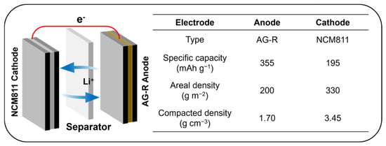
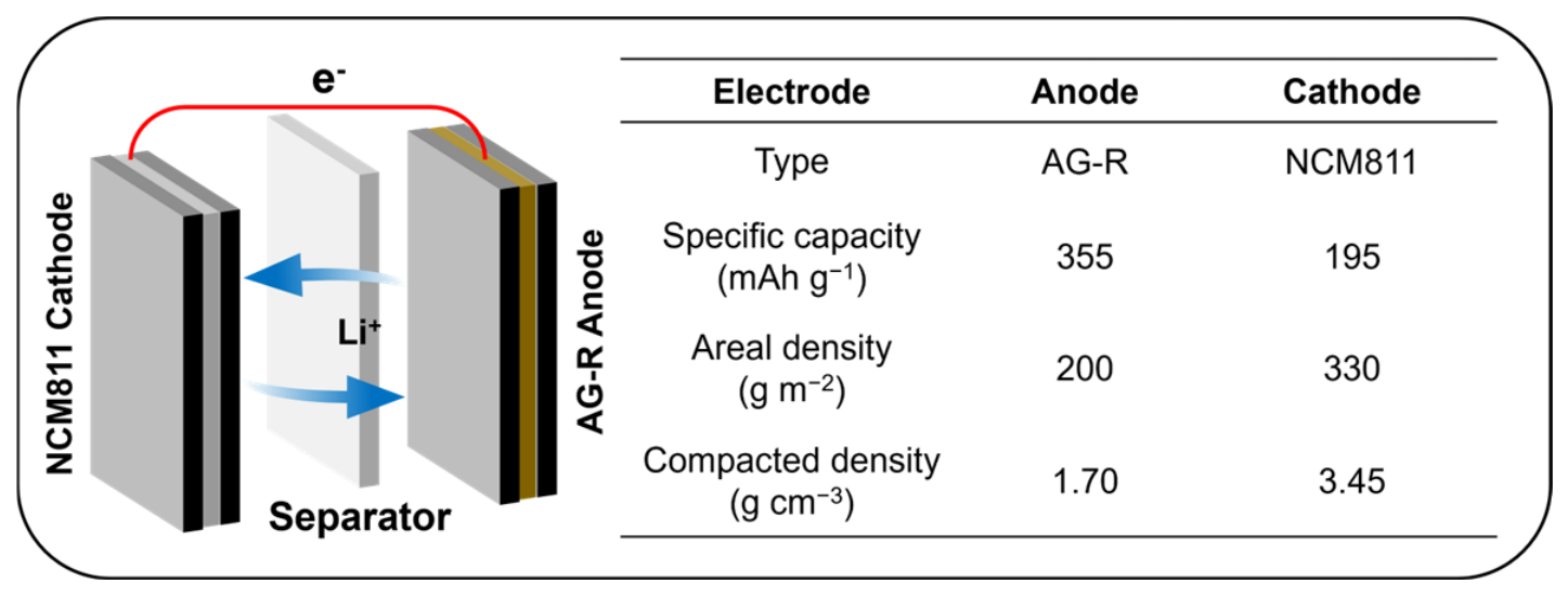
In full-cell assembly, for practical evaluation, 18,650 cylindrical full cells with a nominal capacity of 2.5 Ah were assembled using the prepared AG or AG-R anodes paired with a commercial LiNi0.8Co0.1Mn0.1O2 (NCM811) cathode. The negative-to-positive capacity ratio was controlled at approximately 1.1. The cathode slurry was prepared by mixing NCM811, Super P, and polyvinylidene fluoride (PVDF) at a mass ratio of 95:2.5:2.5 in N-methyl-2-pyrrolidone (NMP). The electrolyte used was identical to that used in half-cells, with an electrolyte amount of 3 g Ah−1 in full cells. Detailed electrode formulations and assembly parameters are provided in Figure 1.
Figure 1.
Detailed electrode formulations and assembly parameters of 18,650 full cells.
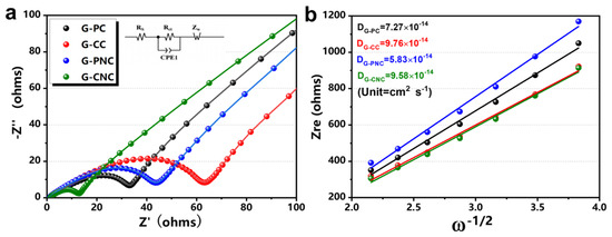
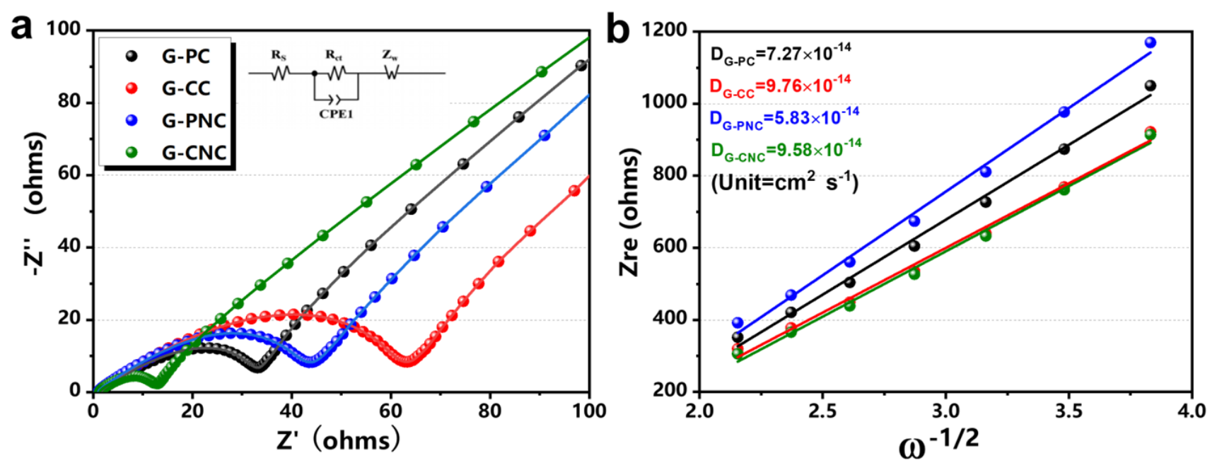
For electrochemical testing, galvanostatic charge–discharge cycling of the half-cells was performed on a LAND CT2001A battery testing system at room temperature. The current density for the initial two cycles was set to 30 mA g−1 (approximately 0.1 C), and subsequent rate capability tests were conducted at 0.1 C, 0.2 C, 0.5 C, 1.0 C, 1.5 C, and 2.0 C (1 C = 300 mA g−1). For full-cell testing, the 18,650 cells were cycled at various charge/discharge rates (0.5 C to 10 C; 1 C = 2.5 A) at 25 °C using a NEWARE CT-4008T battery testing system. Electrochemical impedance spectroscopy (EIS) measurements were performed over a frequency range of 100 kHz to 10 mHz with an AC amplitude of 5 mV. The Li+ diffusion coefficient (DLi+) was calculated from the Warburg region of the EIS spectra using the following equation [26]:
where R is the gas constant (8.314 J mol−1 K−1), T is the absolute temperature (298.15 K), A is the electrode area (1.13 cm2), n is the number of electrons transferred per molecule during intercalation (n = 1), F is the Faraday constant (96,485 C mol−1), C is the molar concentration of Li+ in the graphite electrode, and σ is the Warburg factor obtained from the slope of the linear plot of Z′ versus ω−1/2 in the low-frequency region.
For electrode properties, compaction density was measured by calendaring at different pressures. Electrolyte wettability was evaluated by recording the absorption time of a 1 μL electrolyte droplet on the electrode surface in an argon-filled glovebox (H2O and O2 < 0.1 ppm, 25 °C), with results averaged over three repeated measurements.
3. Results and Discussion
3.1. Precursor-Driven Tuning of Bulk Structural Isotropy for Pitch-Derived Graphites
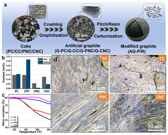
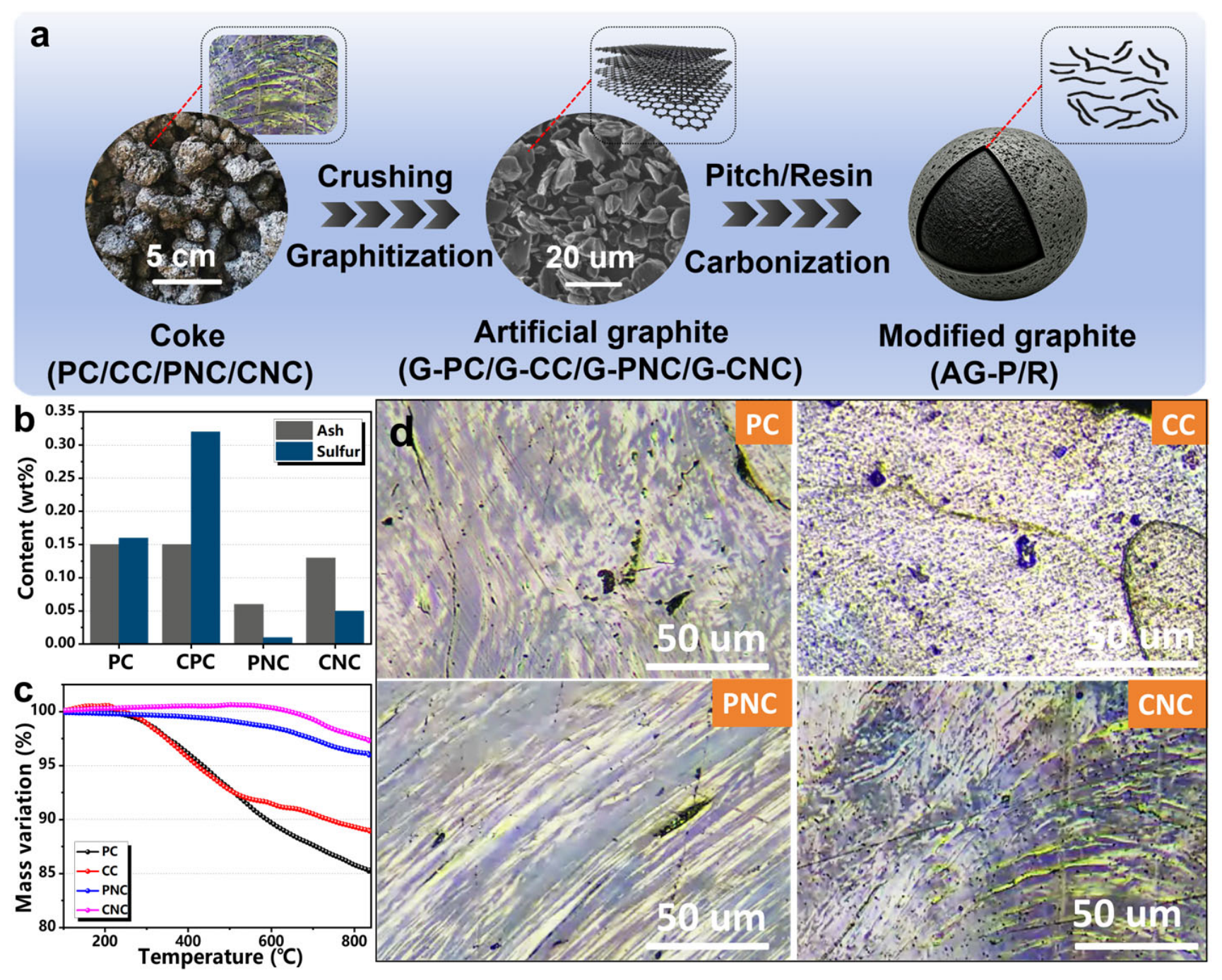
Figure 2a illustrates the fabrication workflow for high-graphitization graphite anodes with mitigated structural anisotropy. Four representative pitch-based coke precursors were screened, followed by high-temperature graphitization and surface amorphous-carbon modification to obtain fast-charging, high-energy-density anode materials for LIBs. The ash and sulfur impurity contents of different coke feedstocks are summarized in Figure 2b. Compared with coal-derived feedstocks, petroleum-origin cokes contained fewer mineral impurities, delivering lower ash and sulfur levels for PC relative to CC. After purification, both PNC and CNC exhibited greatly reduced impurity contents. In particular, sulfur content decreased from 0.16 wt% (PC) and 0.32 wt% (CC) to 0.01 wt% (PNC) and 0.05 wt% (CNC). Such distinct impurity levels play a critical role in governing both the thermal decomposition behavior and the internal micro-textures of the precursors [27,28].
Figure 2.
(a) Schematic illustration of fabrication procedure for core–shell AG-R anode. (b) Ash and sulfur contents, (c) thermogravimetric analysis curves, and (d) polarized-light micrographs of four precursors.
Thermogravimetric analysis (TGA, Figure 2c) was performed under a N2 atmosphere to trace thermal decomposition behavior. PC and CC showed obvious mass loss starting near 300 °C due to their higher volatile content. The carbon yields at 850 °C reached 85.3% for PC and 88.9% for CC. In contrast, needle-coke precursors experienced negligible weight loss below 600 °C, benefiting from their highly condensed aromatic structures, and achieved carbon yields above 95% with superior thermal stability. Polarized-light micrographs (Figure 2d) further reveal the influence of precursor chemistry on internal microstructure. All cokes contain internal pores, yet their domain textures differ substantially. PC exhibited large domain-like regions with sparse but large pores, whereas CC displayed fine mosaic domains with densely distributed small micropores. Subjected to shear force, thermal gradient, and gravitational force during coking, needle cokes form highly aligned striated “needle-like” textures [29]. PNC possessed the highest chemical purity but suffered from the most severe structural anisotropy. In contrast, CNC retained the needle-like oriented texture while also inheriting the abundant micropores characteristic of the CC precursor, offering a distinctive combination of structural order and porosity that is expected to facilitate electrolyte penetration and accommodate volume changes during cycling.
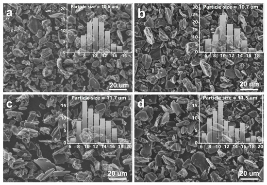
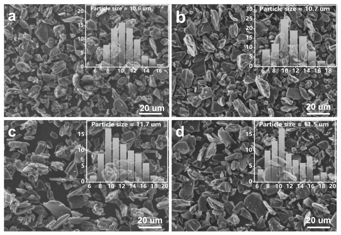
All precursors were crushed and classified to particle sizes near 10 um, then graphitized at 3000 °C for 2 h under an Ar atmosphere. The corresponding SEM images are presented in Figure 3. The oriented texture inherited from needle-coke precursors resulted in a higher proportion of flaky particles formed by the fracture of oriented lamellae during graphitization, compared with PC and CC-derived graphites. In addition, G-PNC and G-CNC exhibited much smoother particle surfaces than G-PC and G-CC. The smoother surface of needle coke-derived graphites is expected to reduce side reactions with the electrolyte and facilitate uniform coating in subsequent modification, both of which are beneficial for improving electrochemical performance [30].
Figure 3.
SEM images of (a) G-PC, (b) G-CC, (c) G-PNC, and (d) G-CNC. Insets show corresponding particle-size distribution histograms.
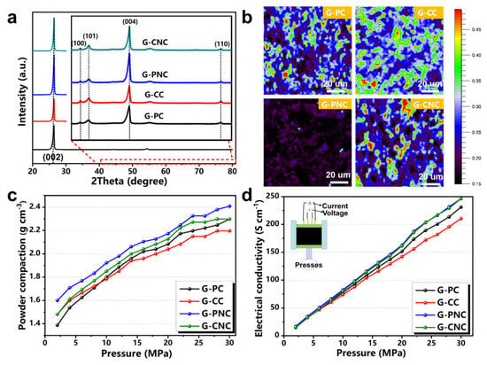
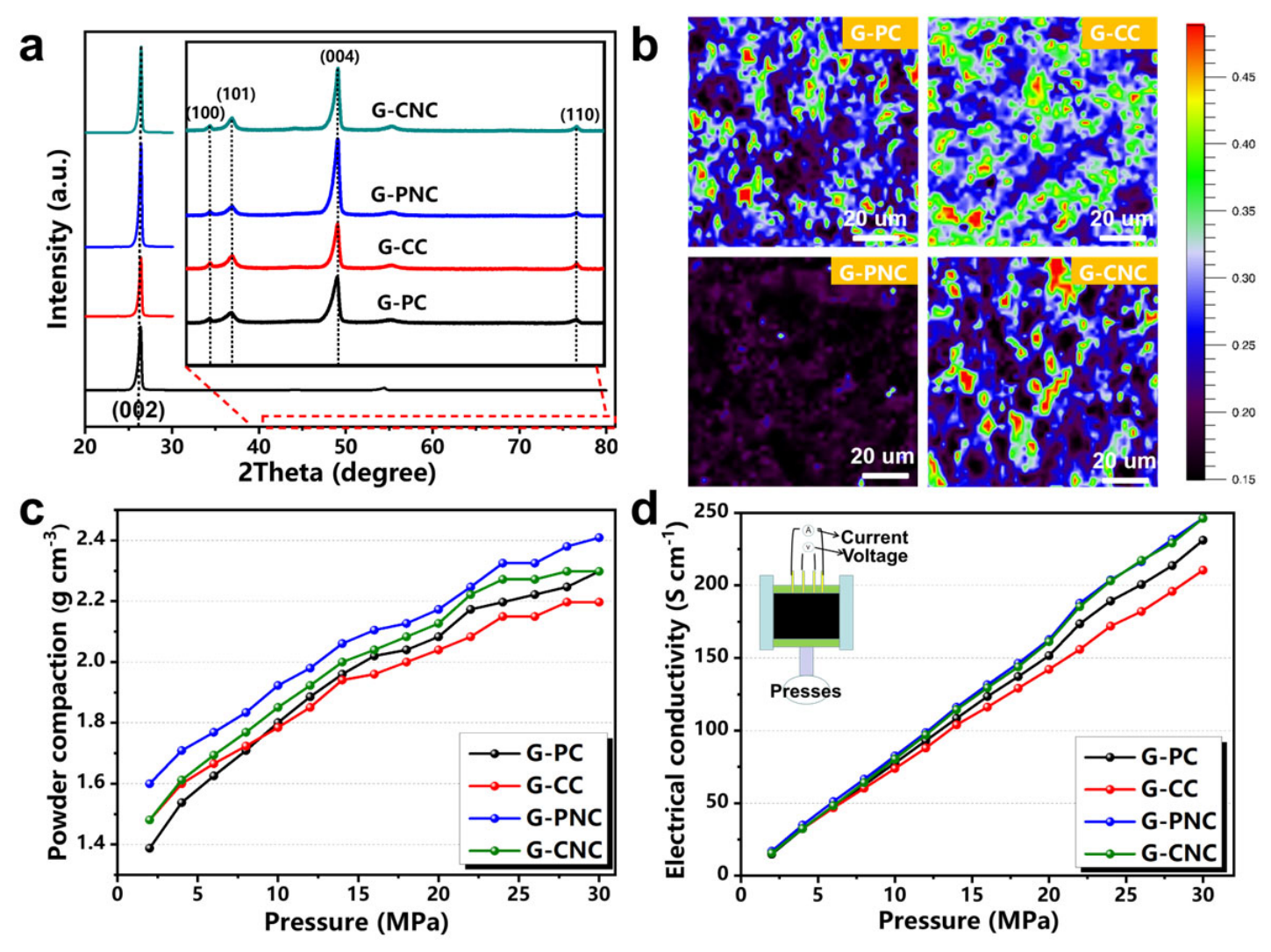
X-ray diffraction (XRD) was employed to investigate crystallographic differences among graphitized samples (Figure 4a). Distinct diffraction peaks assigned to the (002), (100), (101), (004), and (110) crystal planes of graphite were observed at 2θ of about 26°, 42°, 44°, 54°, and 77°, respectively [25,31]. Interlayer spacing d(002), graphitization degree (G), crystallite sizes Lc and La, and orientation index (OI) were calculated and are compiled in Table 1. The lower defect content of PC results in higher graphitization than CC (93.60% vs. 92.29%), confirming that impurities impede crystallite growth. After purification, both needle cokes showed significantly enhanced graphitization: G-PNC achieved the highest G (95.94%) with enlarged Lc and La (2.15 nm and 14.05 nm), while G-CNC also exhibited high G (94.89%) with the largest Lc (2.38 nm) among all samples, indicating that impurity removal effectively promoted carbon atom rearrangement. However, G-CNC had a notably smaller La (13.89 nm) than G-PNC, attributed to the abundant micropores inherited from the CC precursor that physically hinder basal-plane crystallite growth. Consequently, the restricted La suppressed excessive crystallite orientation, yielding a substantially lower OI (10.25) for G-CNC compared to G-PNC (14.82). Thus, G-CNC achieves a favorable compromise: low impurity content enables crystallite growth along the c-axis (high G, large Lc), while inherited micropores restrain excessive in-plane crystallite enlargement (smaller La, low OI), combining high graphitization with improved structural isotropy.
Figure 4.
(a) XRD patterns, (b) Raman mapping images, (c) powder compaction density, and (d) electronic conductivity of graphites derived from four pitch-based precursors.
Table 1.
Structural parameters of graphites derived from four pitch-based precursors.
The Raman mapping results (Figure 4b) visualize the spatial distribution of the structural defects. This false-color map as generated by calculating ID/IG from point-by-point Raman spectra for each pixel. Higher ID/IG values correspond to bright red regions (higher defect density), while lower ID/IG values yield dark blue domains (higher crystallinity and fewer defects) [32]. Pixel-wise averaged ID/IG ratios extracted from mapping are 0.27 for G-PC, 0.32 for G-CC, 0.19 for G-PNC, and 0.22 for G-CNC. G-PNC displays predominantly dark blue signals, consistent with its high graphitization and low defect content. By contrast, G-CC shows widespread red features originating from abundant structural defects. Notably, the low color contrast in the Raman map of G-CC indicates improved structural isotropy, which aligns well with the XRD-derived OI trends. The differences in structural order among the four graphites also manifested in their powder-level physical properties (Figure 4c,d). Higher graphitization generally improves both powder compaction and electronic conductivity. At 30 MPa, the powder compaction density increased from 2.2 g cm−3 (G-CC, lowest G) to 2.4 g cm−3 (G-PNC, highest G), while the electrical conductivity rose from 210.50 S cm−1 to 246.31 S cm−1. Notably, G-CNC achieved electronic conductivity (246.19 S cm−1) comparable to G-PNC (246.31 S cm−1) despite its slightly lower graphitization degree, indicating that precursor purification effectively compensates for the marginal loss in crystallinity.
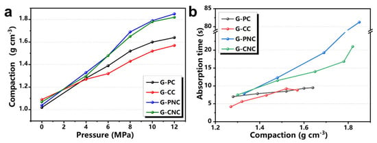
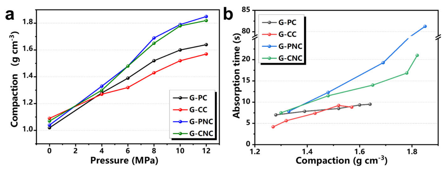
The electrode compaction and electrolyte wettability were further evaluated using electrode sheets prepared under practical full-cell fabrication conditions (Figure 5). The lower graphitization degrees of G-PC and G-CC limited their electrode compaction to approximately 1.6 g cm−3, whereas G-PNC and G-CNC, benefiting from superior crystallinity, attained values exceeding 1.8 g cm−3. Nevertheless, the pronounced anisotropy of G-PNC (OI = 14.82) induced ordered particle alignment during calendering, which enhanced densification at the cost of electrolyte accessibility, as reflected by an electrolyte absorption time exceeding 80 s. In contrast, G-CNC struck an optimal balance between high compaction density and adequate electrolyte wettability.
Figure 5.
(a) Electrode compaction and (b) electrolyte wettability of graphites derived from four pitch-based precursors.
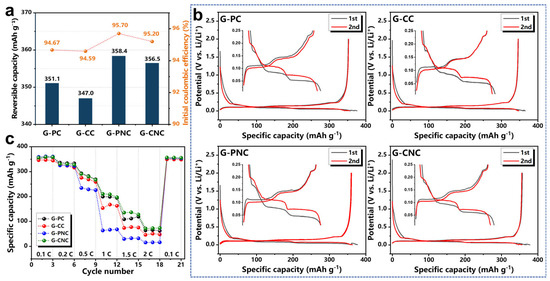
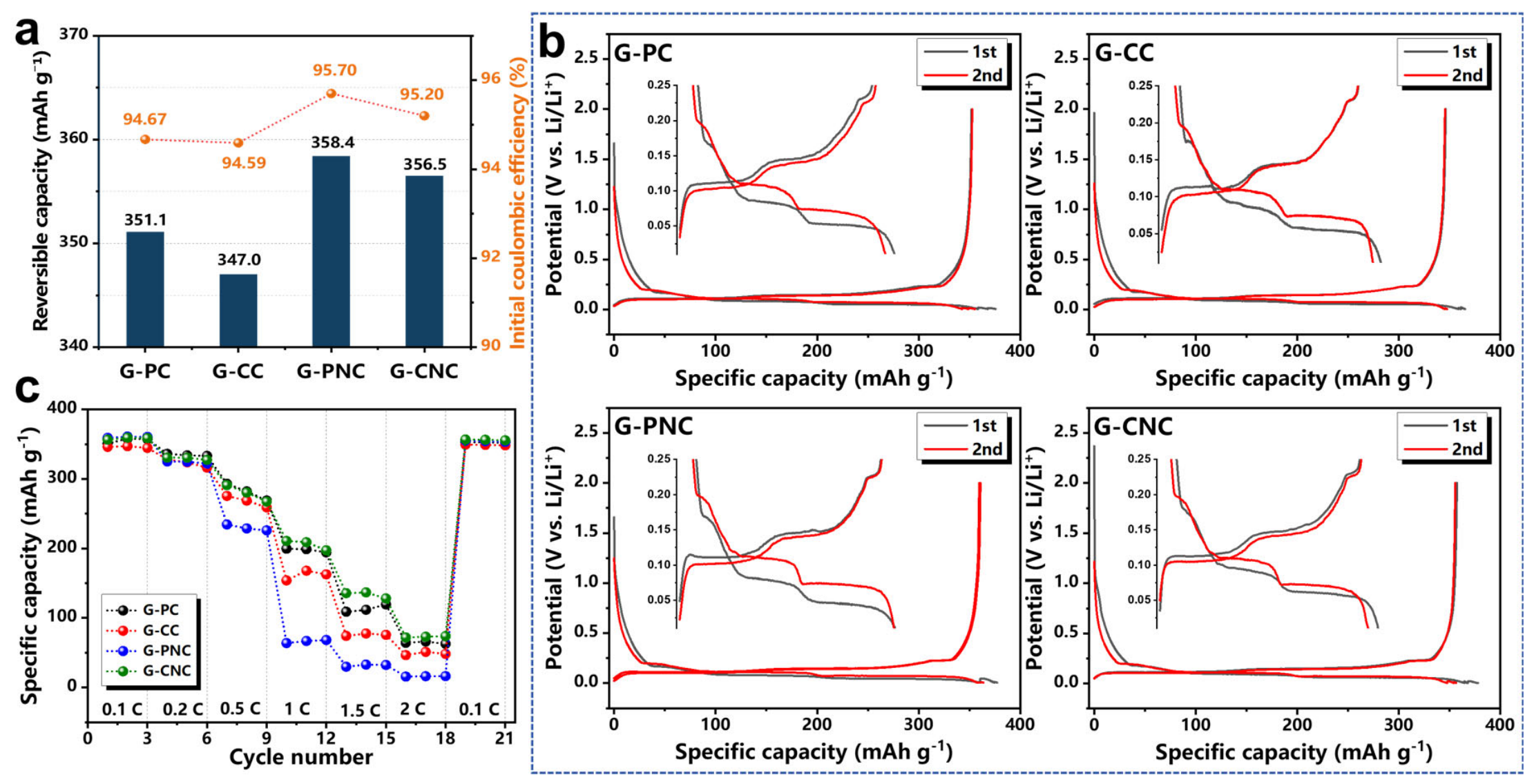
Electrochemical performance was evaluated in CR2032 coin half-cells. At 0.1 C (30 mA g−1), G-PC, G-CC, G-PNC and G-CNC deliver reversible capacities of 351.1, 347.0, 358.4 and 356.5 mAh g−1, with initial Coulombic efficiencies (ICE) of 94.67%, 94.59%, 95.70% and 95.20%, respectively (Figure 6a). Capacity and ICE increase with graphitization degree: a more perfect graphite crystal structure facilitates the formation of LiC6 corresponding to the theoretical specific capacity of 372 mAh g−1, while higher-quality graphite crystallinity suppresses parasitic side-reactions and favors formation of a stable solid-electrolyte interphase (SEI) film. The galvanostatic profiles for the initial two cycles are supplied in Figure 6b. All four graphite samples exhibit three characteristic Li+ intercalation plateaus, corresponding to the stage transitions of graphite during lithiation [26,31]. For the first cycle, these plateaus appear near 0.17 V, 0.08 V, and 0.05 V, which shift to ~0.20 V, 0.12 V, and 0.08 V in the second cycle. Such voltage evolution originates from SEI film formation, which optimizes inter-particle contact and mitigates ohmic polarization. Rate measurements were performed from 0.1 C to 2.0 C (Figure 6c). Capacity divergence became prominent above 0.5 C. Although G-PNC possessed the highest graphitization, severe structural anisotropy impeded cross-plane Li+ migration and yielded poor rate retention. Benefiting from balanced graphitization and moderate isotropy, G-CNC exhibited the optimal rate performance. All samples fully recovered their capacity when switching back to 0.1 C after high-rate cycling, confirming good structural reversibility.
Figure 6.
(a) Reversible specific capacity and initial Coulombic efficiency, (b) charge–discharge curves of first two cycles, and (c) rate performance of G-PC, G-CC, G-PNC and G-CNC in CR2032 half-cells.
EIS measurements were conducted on fresh half-cells to interpret the kinetic differences (Figure 7), and the corresponding fitted parameters are listed in Table 2. The ohmic resistance (Rs) of all samples remained within a narrow range of 1.30–1.71 Ω, indicating similar electrolyte and cell assembly conditions. The higher graphitization degree and electrical conductivity of G-PC led to its markedly lower charge-transfer resistance (Rct) of 33.2 Ω, compared with 59.6 Ω for G-CC. Nevertheless, merely pursuing high graphitization cannot guarantee improved electrochemical performance, as exemplified by G-PNC. Benefiting from its high graphitization, G-PNC possessed fewer surface defects and enabled the growth of uniform and stable SEI films, which tend to lower Rct. However, its excessive crystallographic preferred-orientation (high OI) strongly impeded Li+ transport, producing the lowest DLi+ of 5.83 × 10⁻¹⁴ cm2 s−1 and severe electrode polarization, which accounted for its relatively large Rct of 44.6 Ω. In contrast, G-CNC displayed the lowest Rct of 11.6 Ω and a relatively high DLi+ of 9.58 × 10⁻¹⁴ cm2 s−1, ultimately delivering optimal rate and cycling performance (Figure 6c). Therefore, G-CNC was selected as the preferred graphite matrix balancing high graphitization and acceptable structural isotropy for subsequent surface modification.
Figure 7.
(a) Nyquist plots and (b) plots of Zre versus ω−1/2 in low-frequency region of G-PC, G-CC, G-PNC and G-CNC in CR2032 half-cells.
Table 2.
Fitted EIS parameters of various graphite anodes before cycling.
3.2. Construction of Isotropic Core–Shell Architecture via Amorphous-Carbon Coating
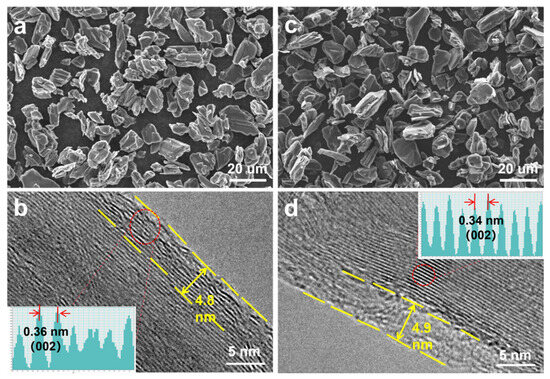
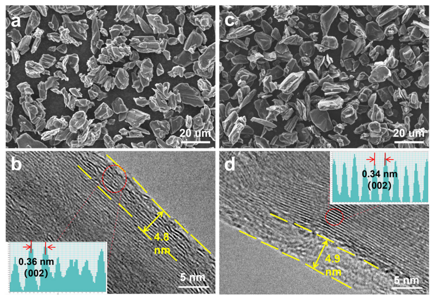
To further promote Li+ transport kinetics, the optimized G-CNC matrix (denoted as AG hereafter) was modified via carbon coating using pitch and phenolic resin as precursors to produce AG-P (pitch-derived soft-carbon shell) and AG-R (resin-derived hard-carbon shell), respectively. SEM and TEM characterizations are displayed in Figure 8. Particle morphology was well-preserved after ball milling and carbonization. HRTEM images verified uniform surface carbon layers with a thickness of approximately 5 nm for both composites. The AG core showed long-range ordered graphite fringes with an interlayer spacing of 0.34 nm. The AG-P shell exhibited relatively ordered carbon fringes (~0.36 nm), whereas AG-R possessed a highly disordered amorphous outer layer. The disordered structure of the resin-derived shell is consistent with the typical hard-carbon microstructure, which is known to contain abundant micropores [33].
Figure 8.
SEM and HRTEM characterizations of (a,b) AG-P, and (c,d) AG-R. Insets in HRTEM panels display lattice spacing profiles.
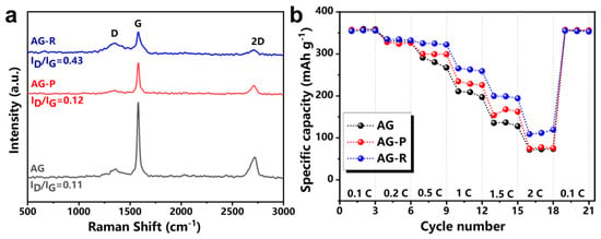
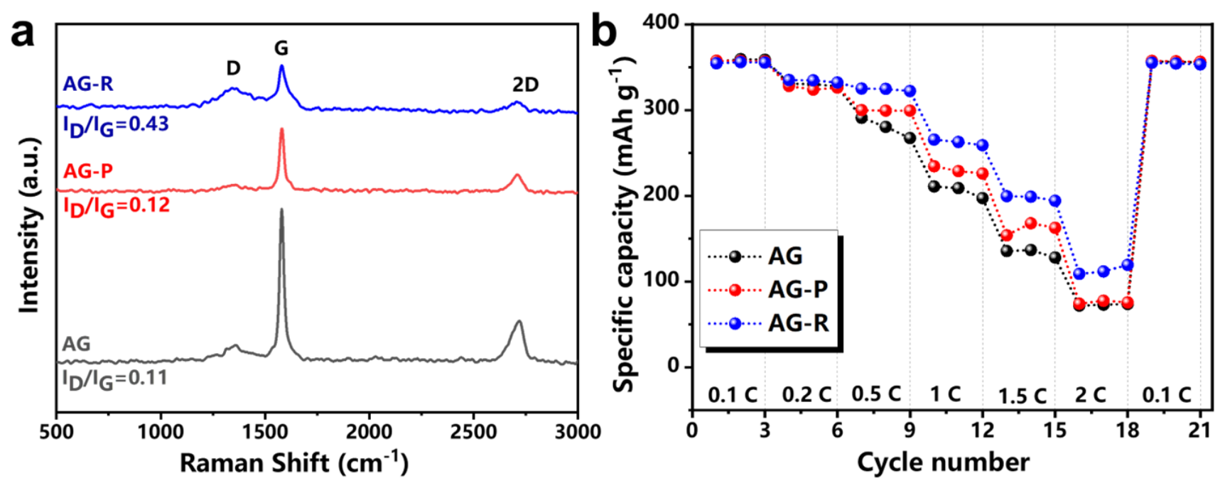
Raman spectra (Figure 9a) probe surface defect levels. The D band (~1350 cm−1) is associated with structural defects and disorder in the carbon lattice, while the G band (~1580 cm−1) corresponds to the in-plane stretching vibration of sp2-hybridized carbon atoms in ordered graphitic domains [34]. The intensity ratio of these two bands (ID/IG) is therefore widely used as a quantitative indicator of structural disorder. The ID/IG ratios are 0.11 for bare AG, 0.12 for AG-P and 0.43 for AG-R. The substantially higher ID/IG ratio of AG-R confirms that resin-derived hard carbon introduces significantly more structural defects than pitch-derived soft carbon under identical carbonization conditions, indicating a more disordered surface structure that is expected to improve the structural isotropy of the graphite surface. The half-cell testing in Figure 9b shows that the amorphous carbon coating does not compromise the intrinsic capacity of AG at low rates (~355 mAh g−1 at 0.1 C). At 2 C, AG-R delivered 119.4 mAh g−1, approximately 1.6 times that of bare AG (73.8 mAh g−1), while AG-P showed only marginal improvement (75.8 mAh g−1). This enhancement is attributed to the role of the resin-derived hard carbon shell as a Li+ transfer station: its disordered and porous structure allows Li+ to be rapidly captured and intercalated into the hard carbon layers. The interconnected channels within the disordered shell then guide Li+ to intercalate preferentially along the basal planes of the ordered graphite core, leveraging the intrinsically faster in-plane diffusion. This two-step process effectively lowers the energy barrier for Li+ intercalation and accelerates overall transport kinetics.
Figure 9.
(a) Raman spectra and (b) rate-performance of AG before and after coating.
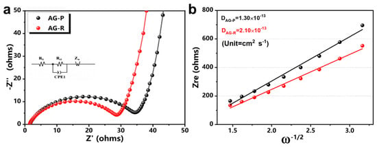
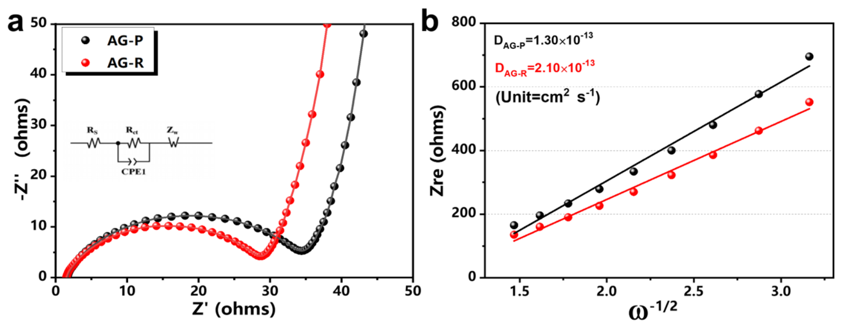
To validate this transfer station mechanism, EIS measurements were performed on fresh half-cells (Figure 10), and the corresponding fitted parameters are listed in Table 3. EIS results revealed that AG-P and AG-R exhibited larger Rct values than bare AG, reaching 33.7 Ω and 27.9 Ω, respectively, a phenomenon stemming from the lower intrinsic electronic conductivity of the carbon coating layer compared with graphite. Nevertheless, resin-derived hard carbon was more favorable for Li+ storage than pitch-derived soft carbon, rendering AG-R not only a lower Rct relative to AG-P but also a substantially higher DLi+ of 2.10 × 10⁻¹³ cm2 s−1 (approximately 2.2-fold that of bare AG and 1.6-fold that of AG-P). These results collectively confirm that the resin-derived hard carbon shell acts as an efficient Li+ transfer station, accelerating both interfacial charge transfer and bulk diffusion.
Figure 10.
(a) Nyquist plots and (b) plots of Zre versus ω−1/2 of AG-P and AG-R.
Table 3.
Fitted EIS parameters of AG-P and AG-R anodes before cycling.
3.3. Performance Evaluation in 18,650 Practical Full-Cells
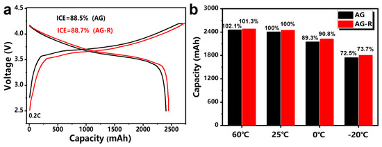
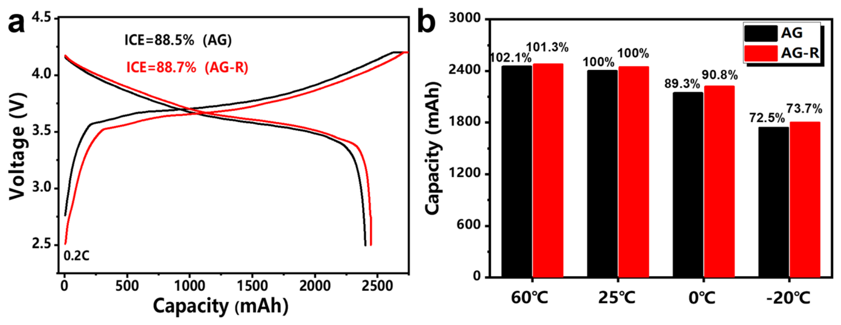
Practical-scale 18,650 cylindrical full-cells (2.5 Ah) were assembled using NCM811 cathodes paired with AG or AG-R anodes. Initial charge–discharge profiles are compared in Figure 11a. NCM811||AG-R delivered a reversible capacity of 2446.2 mAh with an ICE of 88.7%, while NCM811||AG delivered a reversible capacity of 2402.7 mAh with an ICE of 88.5%. AG-R exhibited smaller voltage hysteresis than AG, consistent with its lower cell impedance. The cell achieved an energy density exceeding 430 Wh kg−1 based on the total mass of cathode and anode active materials (median voltage: 3.65 V).
Figure 11.
(a) Initial galvanostatic charge–discharge profiles at 0.2 C and (b) discharge capacity retention at varied temperatures for AG and AG-R.
Temperature-dependent discharge performance is presented in Figure 11b. After being fully charged at 25 °C, the cells were discharged at 0.2 C at −20 °C, 0 °C, 25 °C, and 60 °C. For NCM811||AG, discharge capacity retentions were 72.5% (−20 °C), 89.3% (0 °C), and 102.1% (60 °C). NCM811||AG-R yielded superior low-temperature retentions of 73.7% (−20 °C) and 90.8% (0 °C), demonstrating accelerated ion transport enabled by the resin-derived carbon shell. Meanwhile, the slightly suppressed over-capacity at high temperature (101.3% at 60 °C) indicated mitigated electrolyte side reactions. These results support the proposal that a resin-derived hard carbon shell not only enhances interfacial Li+ transport kinetics but also improves the thermal robustness of the graphite anode, making AG-R a promising candidate for practical high-energy and fast-charging LIBs.
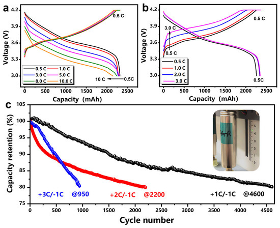
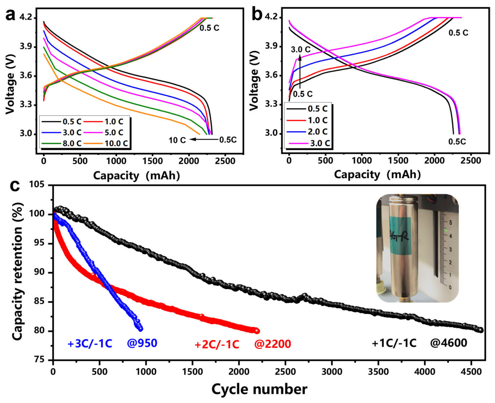
To further validate the impact of the resin-derived hard carbon shell on Li+ transport kinetics, the rate capability of NCM811||AG-R was systematically evaluated. Relative to the capacity at 0.5 C, the cell retained 98.7% of its capacity at 1 C, 98.6% at 3 C, 98.7% at 5 C, 96.7% at 8 C, and 92.3% at 10 C during discharge (Figure 12a). For constant-current charging, the capacity retentions reached 96.9% at 1 C, 87.8% at 2 C, and 81.6% at 3 C (Figure 12b). These results demonstrate that the isotropic and porous nature of the hard carbon shell effectively facilitates rapid Li+ intercalation and de-intercalation, enabling superior rate performance under extreme current densities.
Figure 12.
(a) Rate–discharge curves, (b) rate–charge curves, and (c) long-term cycling stability of NCM811||AG-R.
The long-term cycling stability of NCM811||AG-R was further examined under various charging rates with a fixed 1 C discharge rate (Figure 12c). The 18,650 full-cell retained over 80% of its initial capacity after 4600 cycles at 1 C charge (the slight retention rise near the 2600th cycle was a reversible capacity recovery from the resting interval caused by an unexpected power outage during long-term testing [35]) and after 2200 cycles at 2 C charge and 950 cycles at 3 C charge. Such exceptional durability arises from the synergistic effect of the highly disordered hard carbon shell and the structurally stable graphite core: the shell accommodates interfacial Li+ flux while the core preserves long-range structural integrity. Collectively, the rate and cycling data confirm that the isotropic core–shell architecture not only enhances Li+ transport kinetics but also ensures robust long-term structural stability, positioning AG-R as a promising anode material for high-energy and fast-charging LIBs.
4. Conclusions
In summary, we established a comprehensive precursor–structure–performance evaluation framework for pitch-based artificial graphites, revealing that impurity content, ordered domains, and micropores are the intrinsic factors governing graphite crystallite growth: low impurity content promotes crystallite growth along the c-axis to secure high graphitization; ordered domains facilitate in-plane crystallite growth; and inherited micropores restrain excessive in-plane crystallite enlargement, lowering the orientation index and preserving structural isotropy. Through this systematic analysis, purified coal-based needle coke was identified as the optimal matrix, uniquely combining high graphitization (94.89%) with moderate OI (10.25). Building on this optimized core, a phenolic resin-derived hard carbon coating with substantially higher disorder than its pitch-derived counterpart was applied to construct an isotropic core–shell architecture (AG-R) that preserved the low-rate capacity (~355 mAh g−1 at 0.1 C) while enhancing the Li+ diffusion coefficient by approximately 2.2-fold. In practical 18,650 full-cells, AG-R delivered an energy density exceeding 430 Wh kg−1 (based on the total active material mass), retained 92.3% of its capacity at 10 C discharge and 81.6% at 3 C charge, and sustained over 80% capacity retention after 4600 cycles at 1 C.
Collectively, this work validates that precursor-directed bulk isotropy regulation, enabled by systematic structure–property analysis, combined with surface disordering engineering, provides a viable strategy for developing high-energy and fast-charging graphite anodes for LIBs.
Author Contributions
Methodology, B.K.; investigation, S.L., K.D. and Y.Z.; data curation, L.L.; writing—original draft preparation, L.L.; writing—review and editing, L.L.; formal analysis, W.H.; resources, B.K. and Y.Z. All authors have read and agreed to the published version of the manuscript.
Funding
This work was supported by the Key Research and Development Program of Jiangxi Province (grant No. 20243BBG71031) and the Major Science and Technology R&D Special Project of Jiangxi Province (grant No. 20223AAE02004).
Data Availability Statement
Data will be made available on request.
Conflicts of Interest
Author Wenliang Hu was employed by the company Sunrise (Guizhou) New Energy Materials Co., Ltd. Author Yongcheng Zou was employed by the company Shanggao County Long Time Technology Co., Ltd. The remaining authors declare that this research was conducted in the absence of any commercial or financial relationships that could be construed as a potential conflict of interest.
References
- Besenhard, J.O. The electrochemical preparation and properties of ionic alkali metal-and NR4-graphite intercalation compounds in organic electrolytes. Carbon 1976, 14, 111–115. [Google Scholar] [CrossRef] [Scilit]
- Nikgoftar, K.; Madikere Raghunatha Reddy, A.K.; Reddy, M.V.; Zaghib, K. Carbonaceous materials as anodes for Li-ion and sodium-ion batteries. Batteries 2025, 11, 123. [Google Scholar] [CrossRef] [Scilit]
- Wu, Y.P.; Huang, X.K.; Huang, L.; Chen, J. Strategies for rational design of high-power lithium-ion batteries. Energy Environ. Mater. 2020, 3, 410–437. [Google Scholar] [CrossRef] [Scilit]
- Weng, S.; Yang, G.; Zhang, S.; Liu, X.; Zhang, X.; Liu, Z.; Cao, M.; Ateş, M.N.; Li, Y.; Chen, L.; et al. Kinetic limits of graphite anode for fast-charging Li-ion batteries. Nano-Micro Lett. 2023, 15, 215. [Google Scholar] [CrossRef] [Scilit] [PubMed]
- Abucide-Armas, Á.; Mushtaq, F.; Zulueta, E.; Arcelus, O.; Carrasco, J. Mesoscale heterogeneities in graphite electrodes: Modeling the effect of microstructure and non-ideal anisotropic diffusion on the electrochemical response. J. Energy Storage 2026, 152, 120772. [Google Scholar] [CrossRef] [Scilit]
- Hu, W.; Pan, Y.; Zhong, M.; Wang, L.; Jiang, W.; He, X. Multiscale design strategies for fast-charging graphite anodes in lithium-ion batteries. Small 2026, 22, 73273. [Google Scholar] [CrossRef] [Scilit] [PubMed]
- Dong, Y.; Liu, C.; Rui, M.X.; Zhang, X.; Guan, Y.; Chen, L.; Huang, Q.; Wang, M.; Su, Y.; Wu, F.; et al. Review on graphite anodes for fast-charging Li-ion batteries: Mechanism, modification and characterizations. Adv. Funct. Mater. 2025, 35, 2506190. [Google Scholar] [CrossRef] [Scilit]
- Wang, F.; Lu, A.; Liu, Z.; Zhang, W.; Gao, Y.; Zhao, Q.; Sun, J.; Zhang, C.; Liu, Q.; Liu, H.; et al. Tailoring graphite interlayers with electron-acceptor bridges raises ion diffusion kinetics for ultrafast charging batteries. Adv. Mater. 2025, 37, 2509207. [Google Scholar] [CrossRef] [Scilit] [PubMed]
- Lu, L.; Lu, Y.; Zhu, Z.; Shao, J.; Yao, H.; Wang, S.; Zhang, T.; Ni, Y.; Wang, X.; Yu, S. Extremely fast charging lithium ion battery enabled by dual gradient structure design. Sci. Adv. 2022, 8, eabm6624. [Google Scholar] [CrossRef] [Scilit] [PubMed]
- Niu, M.; Dong, L.; Yue, J.; Li, Y.; Dong, Y.; Cheng, S.; Lv, S.; Zhu, Y.; Lei, Z.; Liang, J.; et al. A fast-charge graphite anode with a Li-ion-conductive, electron/solvent-repelling interface. Angew. Chem. Int. Ed. 2024, 63, e202318663. [Google Scholar] [CrossRef] [Scilit] [PubMed]
- Huang, X.; Ou, Z.; Tu, Y.; Li, G.; Zhang, T.; Ran, F. In situ lithiated anti-perovskite nitride-mediated Li-ion redistribution enabling fast-charging graphite anodes. ACS Nano 2026, 20, 5120–5130. [Google Scholar] [CrossRef] [Scilit] [PubMed]
- Wei, H.; Liu, X.; Pan, H.; Shao, W.; Ju, C.; Yang, Z. Interface modification resolves the fast-charging and thermal stability dilemma of graphite anodes. Compos. Part B 2025, 295, 113238. [Google Scholar]
- Hu, J.; Liu, P.; Ye, S.; Peng, C.; Huang, T.; Mei, R.; Yang, X.; Li, L.; Piao, J.; Jin, B. Scalable synthesis of graphitic aggregates for high-rate battery anode. Nat. Sustain. 2026, 9, 813–817. [Google Scholar] [CrossRef] [Scilit]
- Sun, C.; Ji, X.; Weng, S.; Li, R.; Huang, X.; Zhu, C.; Xiao, X.; Deng, T.; Fan, L.; Chen, L.; et al. 50C fast-charge Li-ion batteries using graphite anode. Adv. Mater. 2022, 34, 2206020. [Google Scholar] [CrossRef] [Scilit] [PubMed]
- Ha, S.J.; Lee, H.C.; Jo, M.S.; Jeon, Y.P. Synthesis and evaluation of petroleum-based impregnating pitch for production of high-performance artificial graphite. J. Ind. Eng. Chem. 2023, 128, 404–411. [Google Scholar] [CrossRef] [Scilit]
- Zhao, L.; Wang, W.; An, X.; Liang, Y.; Liu, R.; Zhou, H.; He, P.; Li, Z.; Ren, J.; Huang, Y.; et al. Short-range promotion and long-range inhibition mechanism of sulfur release in high-sulfur petroleum coke for fast-charging graphite anodes. Chem. Eng. Sci. 2025, 302, 120849. [Google Scholar] [CrossRef] [Scilit]
- Bao, C.; Yang, Z.; Zhan, S. Non-homogeneous graphitization process of petroleum coke enabling distinguished lithium storage. Chem. Eng. J. 2025, 499, 161984. [Google Scholar] [CrossRef] [Scilit]
- Lee, S.H.; Park, C.R. Correlation between graphite morphology and interparticle space affecting rate performance in li-ion battery anodes. Carbon Lett. 2024, 34, 627–636. [Google Scholar] [CrossRef] [Scilit]
- Wu, H.; Si, W.; Zhang, P.; Ji, S.; Yin, B. Intrinsic structural design of graphite anodes for fast-charging lithium-ion batteries: Strategies, trade-offs, and perspectives. Front. Chem. 2026, 14, 1869263. [Google Scholar] [CrossRef] [Scilit] [PubMed]
- Lower, L.; Dey, S.C.; Vook, T.; Nimlos, M.; Park, S.; Sagues, W.J. Catalytic graphitization of biocarbon for lithium-ion anodes: A minireview. ChemSusChem 2023, 16, e202300729. [Google Scholar] [CrossRef] [Scilit] [PubMed]
- Bhattacharyya, S.; Roy, S.; Lin, X.; Campagnol, N.; Vlad, A.; Ajayan, P.M. Graphite: The new critical mineral. Nat. Rev. Mater. 2026, 11, 65–78. [Google Scholar] [CrossRef] [Scilit]
- Zhu, Y.; Liu, H.; Xu, Y.; Hu, C.; Zhao, X. Preparation and characterization of coal-pitch-based needle coke (part III): The effects of quinoline insoluble in coal tar pitch. Energy Fuels 2020, 34, 8676–8684. [Google Scholar] [CrossRef] [Scilit]
- Qiu, T.; Yang, J.; Bai, X. Insight into the change in carbon structure and thermodynamics during anthracite transformation into graphite. Int. J. Miner. Metall. Mater. 2020, 27, 162–172. [Google Scholar] [CrossRef] [Scilit]
- Frank, O.; Tsoukleri, G.; Riaz, I.; Papagelis, K.; Galiotis, C. Development of a universal stress sensor for graphene and carbon fibres. Nat. Commun. 2011, 2, 255. [Google Scholar] [CrossRef] [Scilit]
- Liang, J.; Qin, Z.; Liang, H.; Qin, X.; Li, B.; Kang, F. Polarization reduction through p-doped carbon coatings for fast-charging graphite anodes. Carbon 2026, 260, 121890. [Google Scholar] [CrossRef] [Scilit]
- Xiao, P.; Wang, Z.; Long, K.; Yang, J.; Liu, X.; Ling, C.; Chen, L.; Mei, L. Stable cycling and low-temperature operation utilizing amorphous carbon-coated graphite anodes for lithium-ion batteries. RSC Adv. 2024, 14, 13277–13285. [Google Scholar] [CrossRef] [Scilit] [PubMed]
- Im, J.S.; Lee, C.W.; Halim, H.P. Preparation of needle coke from petroleum by-products. Carbon Lett. 2013, 14, 152–161. [Google Scholar] [CrossRef] [Scilit]
- Rudko, V.A. Needle coke anisotropic structure formation of different structural-group composition petroleum feedstock during carbonization with polymer modification by polystyrene. Colloids Surf. A 2026, 728, 138679. [Google Scholar] [CrossRef] [Scilit]
- Li, X.; Wang, L.; Xie, Y.; Yao, Q.; Sun, M. Preparation of needle coke from low-temperature coal tar pitch based on modification, component separation and component blending. Carbon 2024, 230, 119686. [Google Scholar] [CrossRef] [Scilit]
- Ghosh, S.; Bhattacharjee, U.; Dutta, J.; Sairam, K.; Korla, R.; Martha, S.K. Ultrathin, flexible and smooth carbon coating extends the cycle life of dual-ion batteries. J. Power Sources 2023, 584, 233585. [Google Scholar] [CrossRef] [Scilit]
- Choi, S.; Yang, I.; Lee, B.; Kim, T.H.; Park, S.M.; An, J.C. Toward circular carbon: Upcycling coke oven waste into graphite anodes for Li-ion batteries. Batteries 2025, 11, 365. [Google Scholar] [CrossRef] [Scilit]
- Graf, D.; Molitor, F.; Ensslin, K.; Stampfer, C.; Jungen, A.; Hierold, C.; Wirtz, L. Spatially resolved Raman spectroscopy of single-and few-layer graphene. Nano Lett. 2007, 7, 238–242. [Google Scholar] [CrossRef] [Scilit] [PubMed]
- Liu, L.; Yang, X.; Zhou, N. Highly crosslinked resin prepares hard carbon anode for enhanced sodium storage performance and reduced cost. Chem. Eng. J. 2024, 498, 155876. [Google Scholar] [CrossRef] [Scilit]
- Manno, D.; Orlando, M.M.; Gabriele, A.; Carbone, G.G.; Buccolieri, A.; Calcagnile, L.; Bibi, A.; Benedictis, D.D.; Capitanio, G.; Rasmo, D.D. Optimized synthesis and characterization of highly reproducible carbon dots for bioimaging applications. Colloids Surf. B 2025, 255, 114951. [Google Scholar] [CrossRef] [Scilit] [PubMed]
- Epding, B.; Rumberg, B.; Jahnke, H.; Stradtmann, I.; Kwade, A. Investigation of significant capacity recovery effects due to long rest periods during high current cyclic aging tests in automotive lithium ion cells and their influence on lifetime. J. Energy Storage 2019, 22, 249–256. [Google Scholar] [CrossRef] [Scilit]

Disclaimer/Publisher’s Note: The statements, opinions and data contained in all publications are solely those of the individual author(s) and contributor(s) and not of MDPI and/or the editor(s). MDPI and/or the editor(s) disclaim responsibility for any injury to people or property resulting from any ideas, methods, instructions or products referred to in the content. |
© 2026 by the authors. Licensee MDPI, Basel, Switzerland. This article is an open access article distributed under the terms and conditions of the Creative Commons Attribution (CC BY) license.