


Abstract
Efficient liquid-fuel combustion in micro-combustors strongly depends on fuel atomization, evaporation, and fuel-air mixture preparation. However, conventional straight vaporizer tubes often provide limited droplet breakup and insufficient gas liquid heat and mass transfer. In this study, a honeycomb-corrugated vaporizer tube was proposed to enhance fuel atomization and evaporation before combustion. A computational fluid dynamics model combined with an orthogonal design was employed to investigate the effects of corrugation height, corrugation radius, honeycomb-hole diameter, and number of honeycomb plates on gas–liquid two-phase flow, the Sauter mean diameter (SMD), and fuel evaporation rate. The results showed that corrugation height and the number of honeycomb plates were the dominant factors affecting atomization and evaporation performance. The optimized tube, with a corrugation height of 1.0 mm, a corrugation radius of 4.0 mm, three honeycomb plates, and a honeycomb-hole diameter of 0.6 mm, reduced the outlet SMD from 79.0 μm to 42.6 μm and increased the fuel evaporation rate from 1.5% to 42.0%. These findings provide a feasible structural approach for improving fuel atomization, evaporation, and mixture preparation in small-scale liquid-fuel combustors.
1. Introduction
Micro turbojet engines (MTEs) represent an important class of aerospace propulsion systems. Owing to their compact size and high power-to-weight ratio, they have attracted considerable interest for applications in cruise missiles, intelligent unmanned aerial vehicles, and civilian aeromodels [1,2,3]. Micro gas turbines also show considerable potential for distributed energy systems, including combined cooling, heating, and power generation, range extenders, and hybrid power systems [4,5,6,7]. Compared with large aeroengines, MTEs retain the fundamental multidisciplinary characteristics of gas-turbine systems while offering shorter development cycles and greater flexibility in design iteration.
Aviation kerosene is commonly used as the liquid fuel in MTEs, and combustor efficiency and stability depend strongly on the quality of fuel atomization and evaporation. Poor atomization leads to the formation of large droplets, which increases the probability of droplet–wall impingement, flame displacement, nonuniform outlet temperature distributions, and unstable heat release [8]. Because the minimum ignition energy of a fuel spray increases sharply with droplet size, droplet size reduction is essential for reliable ignition [9]. Spray droplet-size distribution also affects overall engine performance, as well as the reliability and service life of hot-section components [10].
For liquid-fuel combustion, atomization and evaporation are not merely auxiliary processes; instead, they directly determine the rate at which combustible fuel–air mixtures can form prior to the onset of chemical heat release. Because the surface-area-to-volume ratio decreases as droplet diameter increases, larger droplets provide less interfacial area for heat and mass transfer per unit volume of liquid. Consequently, such droplets undergo slower heating and evaporation and are more prone to wall-film formation, resulting in the emergence of local fuel-rich regions. In small-scale combustors featuring short residence times and compact flow passages, inadequate spray evaporation may lead to delayed ignition, flame instability, incomplete combustion, and nonuniform temperature distributions. Therefore, enhancing atomization, evaporation, and heat and mass transfer within the vaporizer tube is essential for improving mixture preparation in micro-combustion systems. Recent reviews and numerical studies have similarly highlighted that atomization quality, droplet size distribution, and vaporization rate exert a profound influence on subsequent evaporation, fuel–air mixing, and combustion efficiency in high-speed turbulent combustion systems [11,12,13].
The vaporizer tube is a key component for fuel atomization and evaporation in a micro turbojet combustor. By promoting fuel–air mixing, droplet breakup, wall interaction, and phase change inside the tube, it directly influences the fuel evaporation rate and Sauter mean diameter (SMD). Accordingly, improving the atomization and vaporization performance of the vaporizer tube is essential to intensify heat and mass transfer, optimize fuel–air mixture preparation, and achieve efficient and stable combustion. Recent studies of liquid-fuel gas-turbine combustors and micro-combustors indicated that injection pressure, spray-combustion chemistry, droplet vaporization, vaporizer-tube arrangement, combustor reference velocity, and airflow distribution among the vaporizer tubes influence mixture preparation, heat release, combustion efficiency, and outlet temperature distribution [14,15,16,17,18,19,20].
Early investigations into micro-vaporizer tubes mainly focused on fundamental physical mechanisms and critical aerodynamic parameters. Zhu and Lin experimentally investigated small T-type and Γ-type vaporizer tubes and demonstrated that the air–fuel ratio, inlet-air temperature, and wall temperature jointly influence evaporation performance [21,22]. Qin developed an integrated cold-spray and hot-evaporation test platform for a 40 daN-class micro turbojet annular combustor and systematically examined the effects of operating parameters on atomization quality and evaporation efficiency [23]. Olivier performed experimental and numerical investigations into gas–liquid flow in vaporizer tubes for micro gas turbines. Collectively, these studies elucidate the fundamental heating, evaporation, and atomization behavior of fuel droplets within vaporizer tubes and lay a foundation for subsequent structural and performance optimization [24].
As demands for higher evaporation efficiency have increased, the drawbacks of conventional straight vaporizer tubes have become increasingly prominent. Therefore, Recent studies have focused on complex internal geometries capable of expanding the heat-transfer area and intensifying airflow disturbance. Zhou optimized corrugated vaporizer tubes, including straight-corrugated and L-type corrugated configurations, and found that their atomization and evaporation performance was significantly improved compared to conventional straight tubes [25]. Wei introduced additive manufacturing into advanced combustor design and developed a vaporizer tube incorporating a helical flow-disturbance structure, demonstrating that the helical inner-wall configuration can significantly improve vaporizer-tube performance [26]. Zhang et al. proposed biomimetic honeycomb-plate and parallel leaf-vein-groove structures for micro turbojet vaporizer tubes, demonstrating that these designs enhance airflow disturbance and increase the effective heat-transfer area, thereby improving fuel evaporation and atomization performance [27,28]. Recent investigations into biomimetic vaporizer tubes and vaporizer-tube micro-combustors have confirmed that optimized internal surface structures and flow-distribution strategies can improve fuel evaporation, atomization quality, and combustion.
Overall, conventional straight vaporizer tubes feature a simple structure and are easy to manufacture, but they generate relatively weak internal flow disturbance and limited secondary droplet breakup, leading to comparatively large SMD values and poor atomization and evaporation performance. Compared with the straight vaporizer tubes, corrugated structures expand the heat-transfer area, modify the near-wall flow, and enhance local flow disturbance, thereby improving fuel evaporation to a certain degree. However, their principal advantage lies in heat-transfer enhancement, while their ability to refine droplets and reduce SMD remains limited. In contrast, honeycomb plates can split and redistribute the airflow, generate localized jets, and facilitate droplet redistribution and secondary breakup. Therefore, integrating honeycomb plates within corrugated tube could simultaneously boost heat transfer and droplet breakup, yielding improved evaporation and atomization performance.
In this study, a honeycomb-corrugated vaporizer tube is proposed to overcome the limited atomization and evaporation performance of conventional straight vaporizer tubes used in micro turbojet combustors. A numerical model combined with an L9(34) orthogonal design was employed to investigate the effects of corrugation radius, corrugation height, honeycomb-hole diameter, and number of honeycomb plates on gas–liquid two-phase flow, fuel-droplet SMD, and evaporation rate. The optimal structural parameters were identified through range analysis, and the performance of the optimized configuration was compared with that of a conventional straight vaporizer tube. The effects of the air–fuel ratio, inlet-air velocity, and wall temperature on the optimized configuration were subsequently evaluated. The results provide a basis for the structural design and performance optimization of vaporizer tubes in micro turbojet combustors.
2. Methods
2.1. Design of the Honeycomb-Corrugated Evaporator Tube
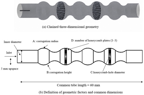
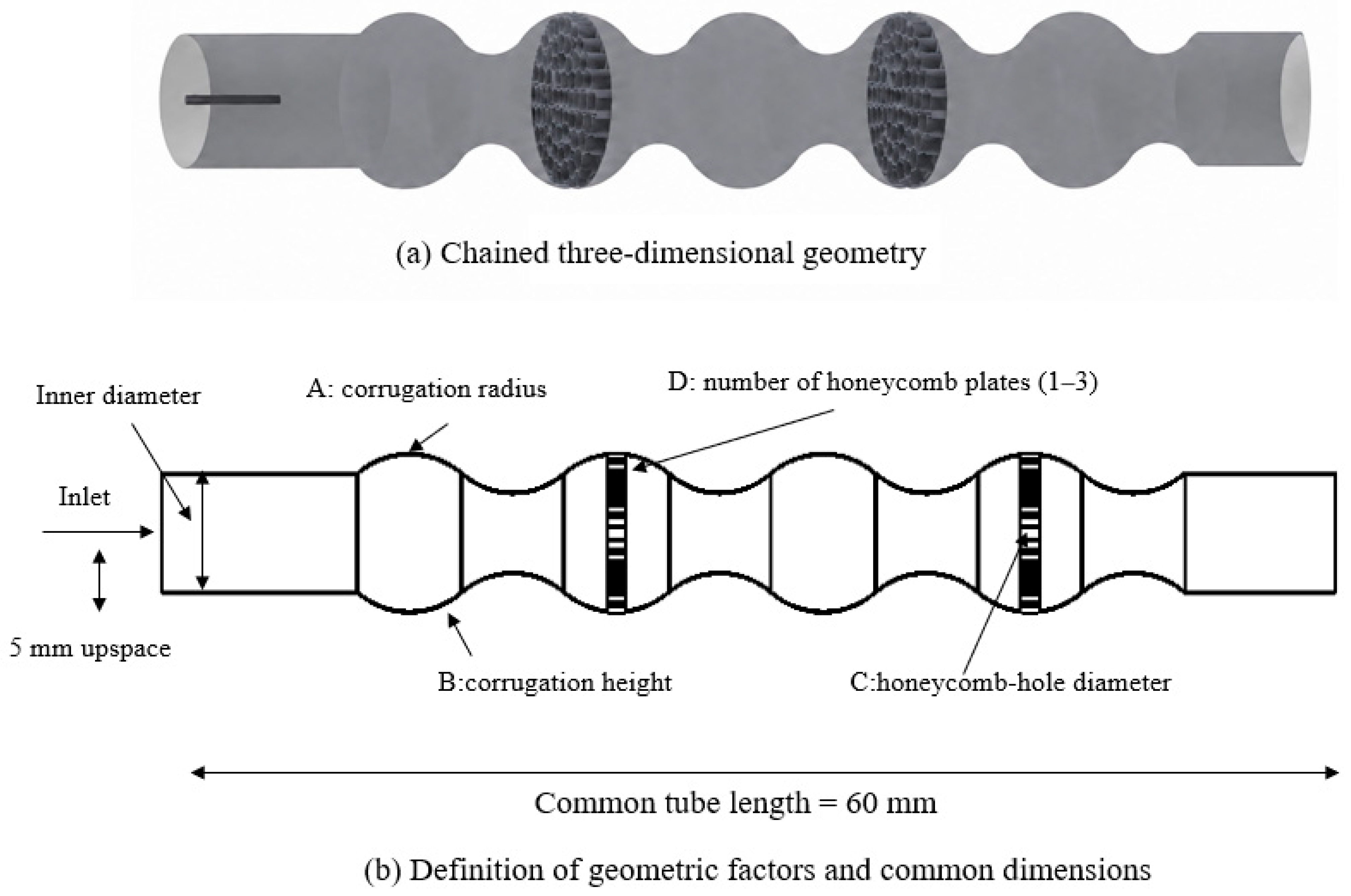
A honeycomb-corrugated vaporizer tube was developed by integrating honeycomb plates into a corrugated passage, as shown in Figure 1a. The honeycomb plates locally partition and accelerate the gas flow, whereas the corrugated wall increases the heat-transfer area and alters the near-wall flow path. Figure 1b defines the four geometric factors used in the orthogonal design and identifies the dimensions held constant across all geometries.
Figure 1.
Geometry and parameter definitions: A, corrugation radius; B, corrugation height; C, honeycomb-hole diameter; D, number of honeycomb plates.
The main analytical framework of this paper is presented as follows: Firstly, an orthogonal test is used to evaluate the influence of geometric parameters and identify the key factors controlling evaporator-tube performance. Secondly, range analysis is carried out to obtain the optimal design. Thirdly, the optimized honeycomb-corrugated tube is compared with a conventional straight tube. Finally, the performance of the optimized tube is evaluated under different operating conditions.
2.2. Numerical Models for Two-Phase Flow, Heat Transfer, and Fuel Evaporation
The flow and fuel spray processes within the vaporizer tube involve turbulent gaseous flow, droplet motion, aerodynamic breakup, droplet heating, liquid evaporation, transport of fuel vapor, droplet–wall impingement, and liquid-film formation. An Eulerian-Lagrangian framework is adopted in this work. The gaseous phase, composed of air and evaporated fuel vapor, is solved within the Eulerian frame, whereas the droplets are tracked as Lagrangian parcels. Two-way coupling is implemented to consider interphase momentum, heat, and mass transfer.
The governing equations for the flow in the evaporator tube include the continuity equation for three-dimensional incompressible flow with constant physical properties, the Navier–Stokes equations for momentum conservation, and the energy-conservation equation.
where u, v, and w are the velocity components in the x, y, and z directions, respectively.
Momentum-conservation equation:
where ρ is the fluid density, P is pressure, ν is the kinematic viscosity, and is the velocity component in the i direction.
Energy-conservation equation:
where α is the thermal diffusivity and T is the fluid temperature.
The continuous gas phase was solved using the steady Reynolds-averaged Navier–Stokes equations because the inlet, outlet, wall-temperature, and injection conditions were time-invariant. Turbulence closure was provided by the Realizable k-ε model with standard wall functions. This choice is consistent with recent comparative evaluations of eddy-viscosity RANS models, which show that standard and realizable k-ε formulations remain a reliable and computationally affordable option for predicting wall-bounded turbulent heat transfer across a wide range of Reynolds and Prandtl numbers [29]. The fuel was represented by Lagrangian parcels using an unsteady, two-way-coupled discrete phase model. Parcel trajectories were determined from the particle force balance, aerodynamic breakup was modeled using the Wave model, and droplet evaporation was coupled to the gas-phase species-transport equation, with C12H23 used as a single-component surrogate for kerosene. The model accounted for gas-droplet convective heat transfer and latent-heat consumption during evaporation, while wall impingement and wall-film transport were handled using the Lagrangian wall-film model.
2.3. Boundary Conditions
Calculations were conducted in Ansys Fluent with a pressure-based solver. The SIMPLE algorithm was employed for pressure–velocity coupling, and second-order upwind discretization for the momentum, turbulence, energy, and species transport equations. The Plain-Orifice Atomizer with 50 injection streams was adopted in this simulation. Liquid kerosene was selected as the injected fuel, and C12H23 was defined as the evaporating species. Fuel injection started at the coordinate (0.005, 0, 0) m along the positive x-direction. The fuel temperature and mass flow rate were set to 300 K and 3.33 × 10⁻⁴ kg/s, respectively. For this atomizer model, constant values of initial droplet diameter and velocity were not specified. Instead, these parameters were computed within Ansys Fluent according to the injector geometry, fuel flow rate and operating conditions. The scaled residual convergence criterion for all transport equations was set to 10−5.
A pressure-inlet boundary condition was applied at the tube inlet, with an inlet gauge pressure of 8000 Pa and inlet-air temperature of 430 K. The outlet was set as a pressure outlet with 0 Pa gauge pressure. The reference pressure was 290 kPa to represent the combustor operating pressure. The fuel temperature was 300 K, the fuel mass-flow rate was 0.333 g/s, and the wall temperature was 800 K.
The total tube length was 60 mm, the nominal inner diameter was 6 mm, and the nozzle outlet was located 5 mm upstream of the vaporizer-tube inlet. These dimensions were identical for all geometries, as summarized in Figure 1b.
Based on the nominal tube diameter and the calculated air mass-flow rates, the bulk Reynolds numbers of the honeycomb-corrugated configurations ranged from approximately 1.32 × 10⁴ to 2.99 × 10⁴, while that of the conventional straight tube was approximately 3.29 × 10⁴. These values support the use of a turbulence model for the present calculations. At these bulk Reynolds numbers, a steady Reynolds-averaged closure remains an appropriate and cost-effective choice, since fully resolving eddy-simulation approaches would substantially increase computational cost without a commensurate gain in predictive accuracy for the present engineering-scale geometry [30].
2.4. Grid-Independence Verification
A hybrid unstructured mesh was employed, with hexahedral cells in the central flow region and tetrahedral cells in the near-wall and geometrically complex regions. Local refinement was applied at the nozzle outlet, honeycomb apertures, corrugation transitions, and the vaporizer-tube wall.
The central-region target size was 0.12–0.15 mm, with minimum and maximum element sizes of 0.03 and 0.20 mm, respectively. The target sizes were 0.04 mm at the nozzle outlet, 0.04–0.06 mm around the honeycomb apertures, 0.06–0.08 mm in the corrugation regions, and 0.06 mm near the wall. The mesh growth rate was limited to 1.20.
Conventional prism inflation layers were omitted. Instead, tetrahedral cells were adopted to refine the near-wall region, ensuring the maximum wall y+ in the calculations remained below 30. The same meshing strategy and local-sizing criteria were applied to all the configurations.
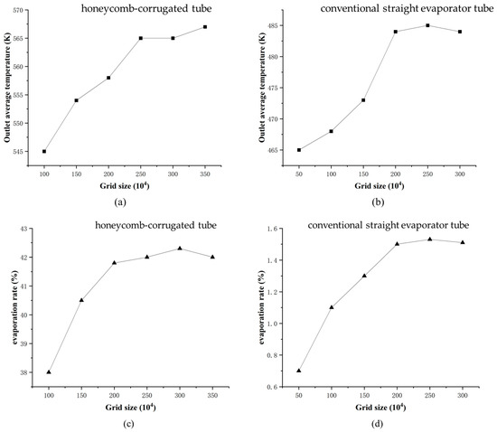
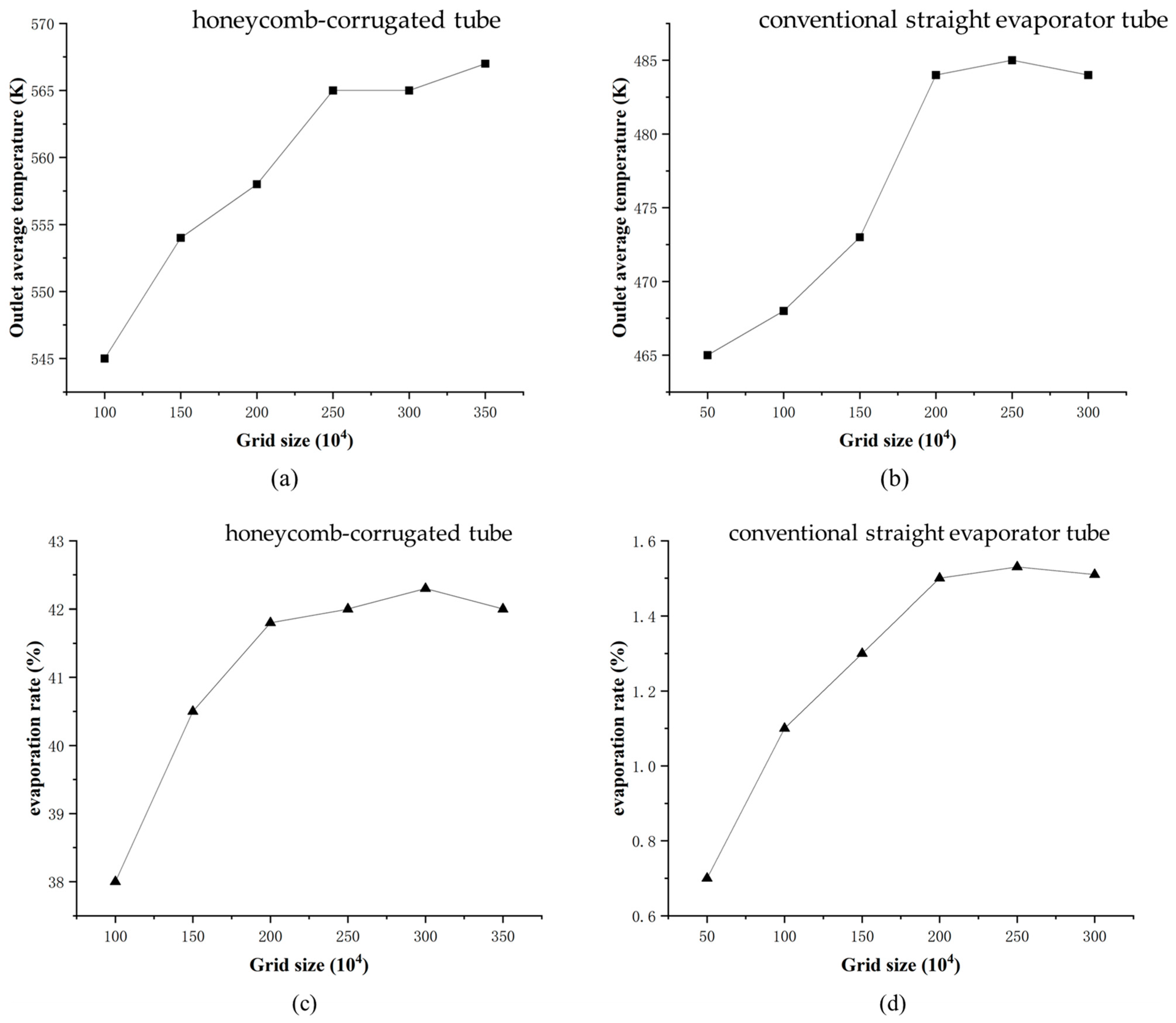
Coarse, medium, and fine meshes were generated by systematically varying the global and local element sizes while maintaining the same refinement regions. Based on the grid-independence results, meshes containing approximately 2.0 × 10⁶ cells for the conventional straight tube and 2.5 × 10⁶ cells for the honeycomb-corrugated tube were selected for subsequent simulations. Grid-independence verification was then performed, as shown in Figure 2.
Figure 2.
Grid-independence verification for the honeycomb-corrugated and conventional straight evaporator tubes: (a,c) honeycomb-corrugated tube; (b,d) conventional straight evaporator tube.
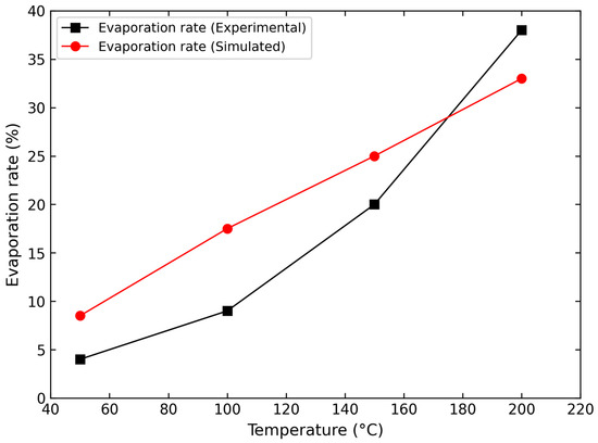
To verify the reasonableness of the selected numerical model and the reliability of the computational methodology, this section compares the present results against the vaporizer-tube atomization and evaporation experimental data reported by Wang et al. [31]. In the validation case, aviation kerosene was used as the fuel, and a single-hole plain-orifice nozzle with an orifice diameter of 0.6 mm was employed. The air pressure difference between the vaporizer-tube inlet and outlet was 4000 Pa, the inlet-air temperature was 150 °C, the inlet fuel-to-air mass ratio was 0.34, and the vaporizer-tube lengths were 80 mm and 120 mm, respectively. In the numerical simulations, the geometric model, boundary conditions, and fuel injection parameters were kept consistent with the experimental setup. The comprehensive applicability of the model adopted in this study was assessed by comparing the trends in evaporation rate under different temperature conditions.
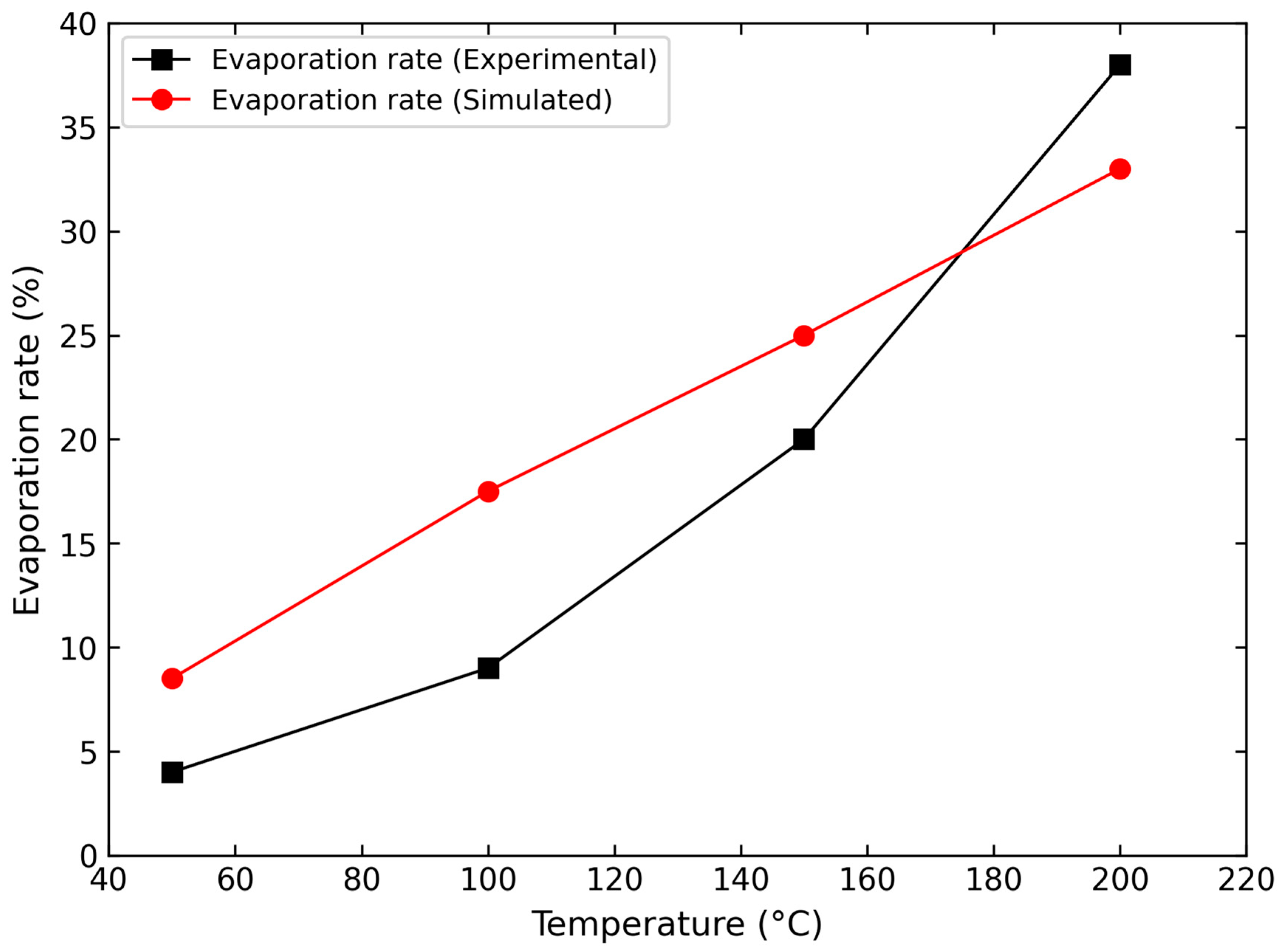
Figure 3 presents the comparison between the experimental and simulated evaporation rates as a function of temperature. Overall, as the temperature increased from 50 °C to 200 °C, both the experimental and numerical results exhibited a pronounced upward trend, indicating that the established model can capture the promoting effect of elevated temperature on fuel heating and evaporation. In the low-temperature range, the simulated values were somewhat higher than the experimental values. This discrepancy is likely attributable to the use of a single surrogate component to represent the evaporation process of aviation kerosene in the numerical simulations, whereas real aviation kerosene is a multi-component mixture whose various fractions differ in initial boiling point, final boiling point, and diffusion characteristics. In addition, wall heat losses, injection fluctuations, and droplet-collection errors in the experiments may also have contributed to the lower measured evaporation rates under low-temperature conditions. As the temperature increased to the 150–200 °C range, the deviation between the simulated and experimental values decreased markedly, and the two datasets exhibited consistent trends, demonstrating that the numerical method adopted in this study achieves good predictive capability in the high-temperature evaporation regime. Because the vaporizer tube of a micro turbojet engine typically operates under relatively high wall temperatures and strong convective heat transfer during actual service, the present model is considered adequate for the comparative analysis and parameter optimization of atomization and evaporation performance among different vaporizer-tube configurations investigated in this study.
Figure 3.
Variation in evaporation rate with temperature.
2.5. Selection of Characteristic Cross-Sections
A mid-plane cross-section was selected for analysis when evaluating the effects of evaporator-tube geometry and inlet-flow parameters on fuel atomization and evaporation. The main performance metrics were fuel droplet SMD and fuel evaporation rate. SMD values at each cross-section were extracted directly from the numerical simulation. The evaporation rate was calculated from the simulated evaporated fuel mass and was defined as the ratio of evaporated fuel to total injected fuel.
2.6. Orthogonal Test Design
To investigate the effects of geometric parameters on evaporator-tube performance, an orthogonal design of experiments (DOE) was adopted. This method reduces the number of numerical simulations while providing reliable factor-effect analysis. Based on an L9 (34) orthogonal array, four geometric control parameters were selected, each with three levels, as listed in Table 1. A denotes corrugation radius, B denotes corrugation height, C denotes honeycomb-hole diameter, and D denotes the number of honeycomb-plate layers. For example, A1 represents a corrugation radius of 3 mm and B1 represents a corrugation height of 0.5 mm. Case a has the combination A1B1C1D1, corresponding to a corrugation radius of 3 mm, corrugation height of 0.5 mm, honeycomb-hole diameter of 0.4 mm, and one honeycomb plate.
Table 1.
Orthogonal test arrangement for geometric control factors.
3. Results
3.1. Effect of Geometric Parameters on Air Velocity in the Evaporator Tube
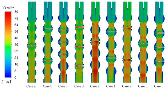
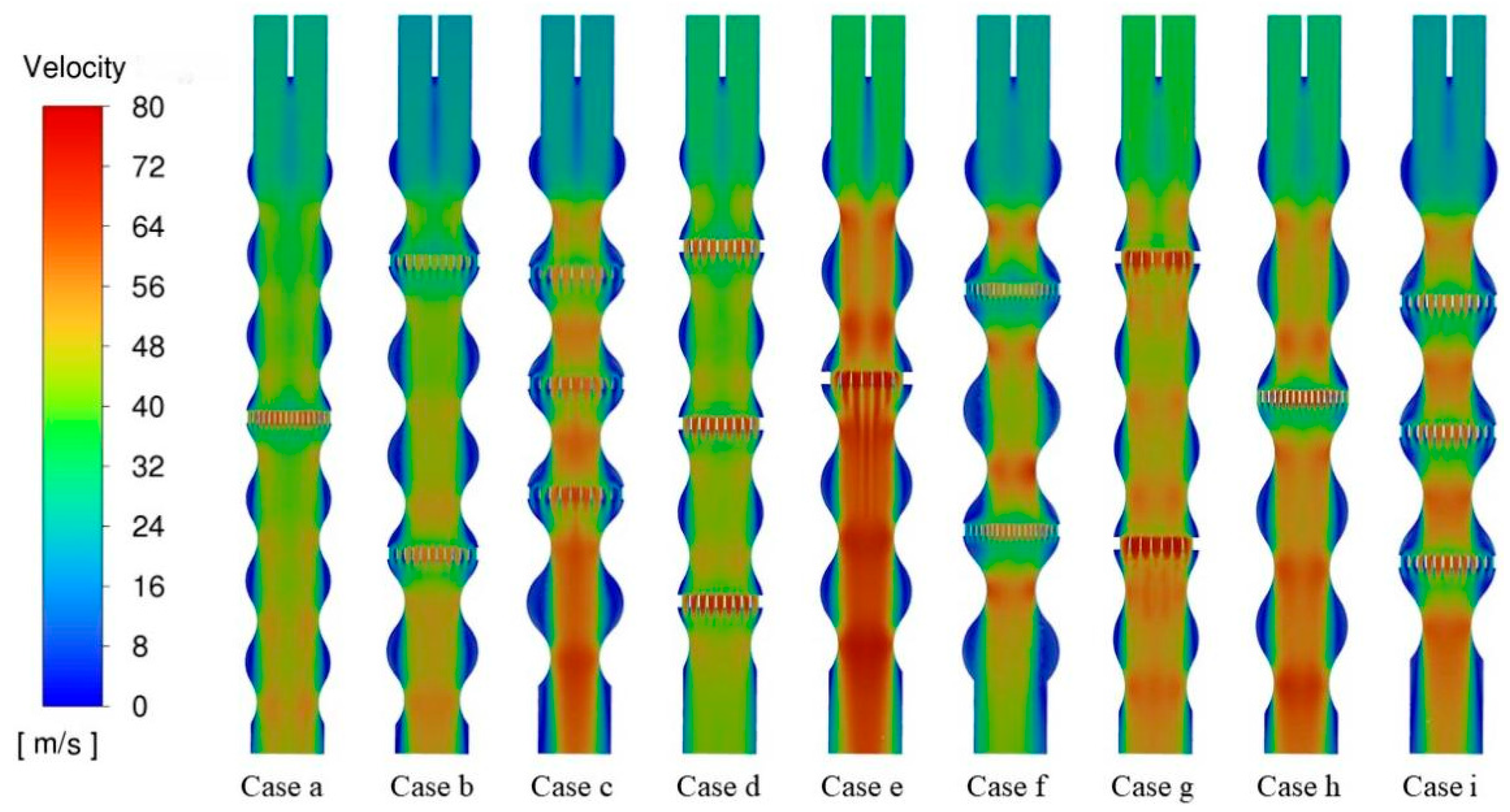
Figure 4 shows the comparison of the air-velocity distributions at the middle cross-section of the evaporator tube, while Table 2 provides the corresponding outlet mean temperature and evaporation-performance parameters. The periodic contraction and expansion of the corrugated tube continuously modulates the flow-channel area along the axial direction. Airflow undergoes compression and acceleration in constricted segments and near honeycomb holes to generate strip-like high-speed regions, while reduced flow velocity and low-speed recirculation zones occur within expanded sections and corrugation troughs.
Figure 4.
Comparison of air-velocity distributions at the middle cross-section of the evaporator tube.
Table 2.
Performance comparison among the honeycomb-corrugated evaporator-tube cases.
Figure 4 shows that the corrugated passage and honeycomb apertures produce repeated local acceleration and deceleration along the flow direction. Cases c, d, and i exhibit distinct localized high-velocity regions near and downstream of the honeycomb apertures.
According to Table 2, Case i maintains an air mass flow rate of 2.56 g/s and exhibits repeated airflow redistribution along the corrugated passage. It achieves the highest outlet mean temperature of 565 K, the highest evaporation rate of 42%, and the smallest outlet SMD of 42 μm. Cases c and f also show relatively favorable performance, with evaporation rates of 30% and 34% and outlet SMD values of 49 and 47 μm, respectively.
Collectively, Figure 3 and Table 2 indicate that repeated acceleration and deceleration arising from honeycomb plates and corrugated walls facilitate improved atomization and evaporation. Among all the configurations, Case i exhibits the most favorable flow organization and the best overall performance.
3.2. Effect of Geometric Parameters on Air Temperature in the Evaporator Tube
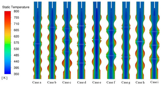
Figure 5 compares the air temperature distributions on the middle cross-section of the vaporizer tube, and Table 2 provides the corresponding outlet mean temperature and evaporation-performance parameters. For all the configurations, a high-temperature zone exists adjacent to the heated wall, alongside a relatively low-temperature region within the central flow passage. However, the scale of the low-temperature core and the inward penetration of the high-temperature zone toward the tube center vary substantially across different configurations.
Figure 5.
Comparison of air-temperature distributions at the middle cross-section of the evaporator tube.
Cases a, d, and g with a corrugation height of 0.5 mm maintain relatively large low-temperature core regions. Their average temperatures of outlet are 475 K, 490 K, and 479 K, respectively, corresponding to evaporation rates of 18%, 22%, and 18%. By contrast, Cases c, f, and i, featuring a corrugation height of 1.0 mm, show a more pronounced temperature rise within the central region. Their outlet mean temperatures increase to 525 K, 543 K, and 565 K, with the corresponding evaporation rates reaching 30%, 34%, and 42%, respectively.
According to the factor level averages obtained from the orthogonal design, increasing the corrugation height from 0.5 mm to 1.0 mm raises the average outlet temperature from approximately 481.3 K to 544.3 K and the average evaporation rate from approximately 19.3% to 35.3%. Meanwhile, the average outlet SMD decreases from approximately 71.3 μm to 46.0 μm. As illustrated in Figure 4, Case i exhibits the smallest central low-temperature region. It also delivers the maximum outlet average temperature of 565 K, the highest evaporation rate of 42%, and the minimum outlet SMD of 42 μm. These results indicate that the radial redistribution of gas temperature observed in Figure 4 agrees well with the quantitative evaporation-performance results listed in Table 2. A higher and more uniform gas-temperature field provides a more favorable thermal environment for droplet heating and evaporation.
3.3. Effect of Geometric Parameters on Fuel-Droplet Atomization and Evaporation
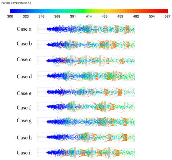
Figure 6 compares the temperature distributions of fuel droplets. After being injected from the nozzle, fuel droplets initially have a low temperature and absorb heat downstream through two main mechanisms: radiation and conduction from the hot wall, and convective heat transfer from the hot gas. Since convective heat-transfer intensity is proportional to the gas–liquid relative velocity and temperature difference, the high-speed jets adjacent to the honeycomb plates deliver important local enhancement to droplet heating.
Figure 6.
Comparison of fuel-droplet temperature distributions.
In Cases a and e with fewer honeycomb plates, the droplet temperature distribution retains a clear center-jet pattern. Driven by inertia, droplets move mainly downstream along the centerline with limited radial spreading. Many droplets therefore remain concentrated in the central mainstream region and fail to fully enter the near-wall and corrugation-crest regions, diminishing their opportunity for direct wall-contact heat transfer.
By contrast, Cases c, f, and i adopt multi-stage honeycomb plates. The honeycomb plates disrupt the continuity of the center jet and induce intense disturbance and secondary flow, forcing droplets to migrate radially outward from the center toward the wall. This substantially improves droplet distribution near the corrugation crests and enables more efficient utilization of the corrugated tube geometry for heat transfer.
Combining the observations in Figure 5 and data in Table 2, large corrugation height effectively disrupts the near-wall laminar thermal boundary layer and strengthens radial mixing. The strengthened radial heat transport removes the low-temperature core and increases the temperature gradient around the central droplet cloud, facilitating rapid droplet heating. Multiple honeycomb plates also create multi-stage shear interfaces. Intense aerodynamic shear promotes secondary atomization and accelerates the dissipation of the saturated vapor layer at the droplet surface, thereby reducing mass transfer resistance.
Table 3 shows the numerical results for the nine honeycomb-corrugated evaporator-tube configurations. The data show that internal structural parameters significantly affect flow resistance, heat-transfer capability, and fuel evaporation behavior. Obvious discrepancies exist among all the cases with respect to air mass flow rate, outlet mean temperature, evaporation rate, and outlet droplet SMD.
Table 3.
Orthogonal range analysis based on fuel evaporation rate.
Case a yields the minimum air mass flow rate of merely 1.5 g/s, with an average temperature of 475 K, an evaporation rate of only 18%, and the maximum SMD of 82 μm at the outlet. This indicates that the configuration strongly blocks the internal flow channel and reduces flow capacity. Owing to unfavorable flow organization, effective gas–liquid heat transfer and mixing cannot be realized, leading to weak atomization and evaporation.
Case g achieves the maximum air mass flow rate of 3.4 g/s, which corresponds to the lowest internal flow resistance and the strongest through-flow capacity. However, its outlet average temperature is merely 479 K with an evaporation rate of only 18%, leading to inferior overall evaporation performance. Although low flow resistance improves flow capacity, excessive gas velocity shortens droplet residence time and weakens radial disturbance and local mixing. As a result, droplets are swept out before absorbing sufficient wall heat, limiting the improvement in evaporation performance.
Case f features a relatively low air mass flow of 1.8 g/s, indicating high internal flow resistance. Meanwhile, intensified flow disturbance promotes local mixing and prolongs droplet residence in high-temperature zones, raising the outlet mean temperature to 543 K and the evaporation rate to 34%. It follows that an appropriate increase in flow resistance can reinforce heat transfer and evaporation within a reasonable range, even though the sacrifice of through flow capacity.
Overall, Case i provides the best combined performance. It reaches the highest outlet average temperature of 565 K and the highest evaporation rate of 42%, together with the minimum outlet SMD of 42 μm. Its air mass flow is 2.56 g/s. Its moderate air mass flow rate of 2.56 g/s realizes a good balance between flow resistance and through-flow capacity. Therefore, Case i effectively strengthens internal heat transfer, extends droplet residence time, and improves gas–liquid mixing while maintaining sufficient air flow.
3.4. Orthogonal Test Analysis
In the orthogonal analysis, evaporation rate was selected as the single evaluation index, and the corresponding range analysis results are summarized in Table 3. Rows K1, K2, and K3 represent the sums of evaporation rates corresponding to levels 1, 2, and 3 of factors A, B, C, and D, respectively. The rows k1, k2, and k3 are the average values of the corresponding K rows (e.g., k1 = K1/3). The range value is defined as the difference between the maximum and minimum k values for each factor. A larger range indicates a greater influence on evaporation rate, and the factor with the maximum range serves as the dominant parameter.
Table 3 shows that the influence of the geometric parameters on evaporation rate follows the order B (corrugation height), D (honeycomb-plate layers), C (honeycomb-hole diameter), and A (corrugation radius). From the orthogonal analysis, the optimal parameter combination is A3B3C2D3, which corresponds to Case i and is fully consistent with the best numerical-simulation result. This agreement indicates that the orthogonal-analysis method is reliable for optimizing the evaporator-tube structural parameters.
3.5. Comparison Between the Honeycomb-Corrugated Tube and a Conventional Straight Tube
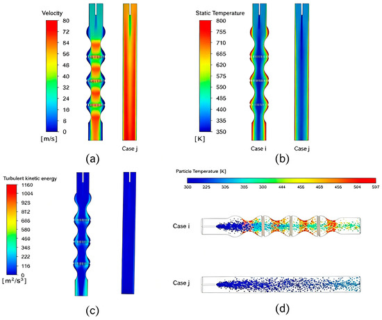
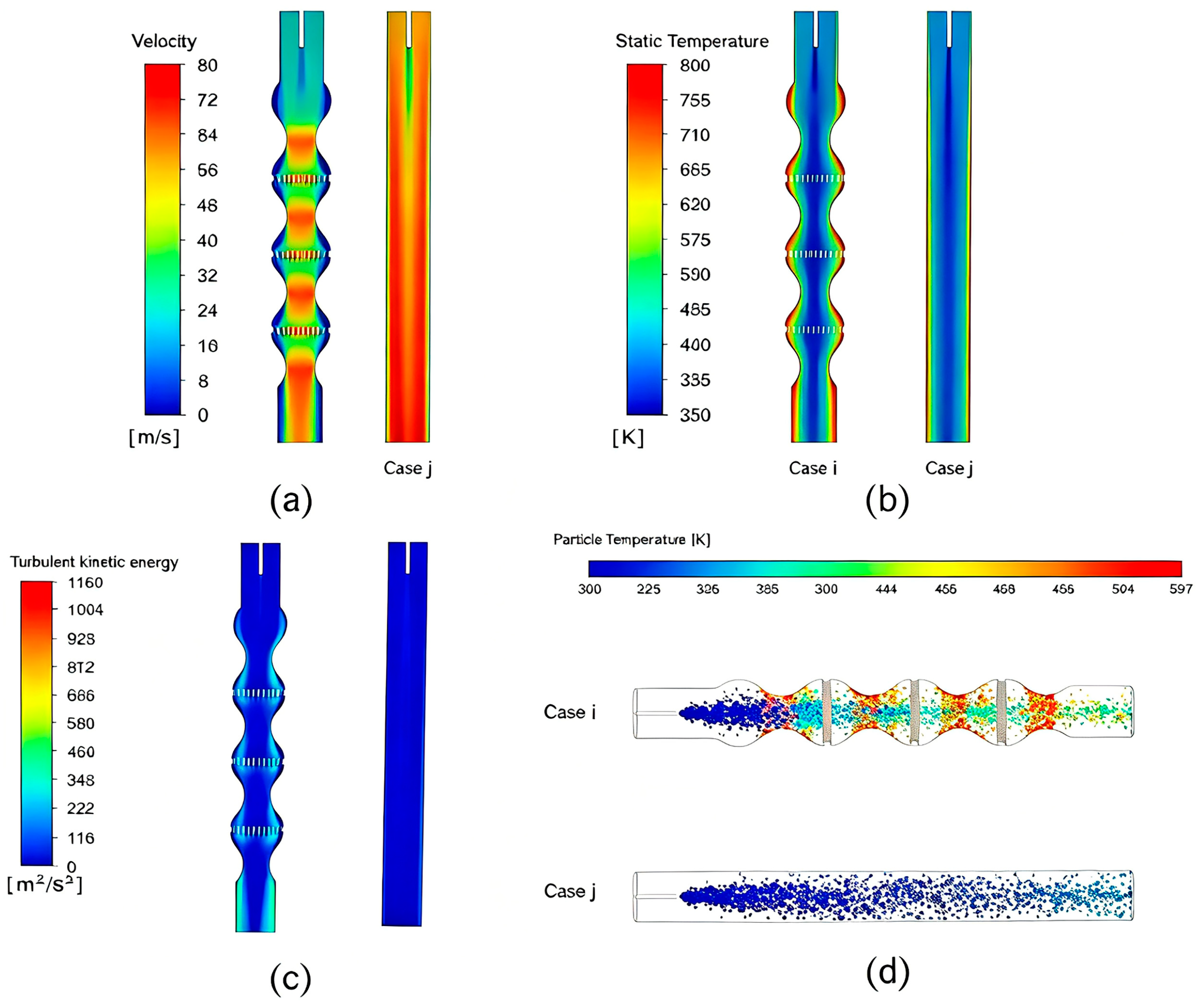
A conventional straight evaporator tube, denoted as Case j, was simulated by the same numerical model and boundary conditions for comparison with the optimized Case i. The results are shown in Table 4 and Figure 6. Table 4 shows that the evaporation rate of the conventional straight tube merely reaches 1.5%, while the optimized honeycomb-corrugated tube achieves 42%. This large improvement is mainly attributed to improved flow field organization and heat-transfer enhancement. Firstly, the outlet turbulent kinetic energy increases from 24.57 m2/s2 (Case j) to 182.37 m2/s2 (Case i), indicating stronger modeled turbulent fluctuations and more intensive flow redistribution. Secondly, the heat absorbed per unit mass of air increases from 95 kJ/kg to 201 kJ/kg, and the outlet average air temperature rises from 484 K to 565 K. Thirdly, under the combined action of aerodynamic shear and wall impingement, the outlet SMD decreases from 79 μm to 42.6 μm, confirming the marked improvement in atomization quality.
Table 4.
Performance comparison between the optimized honeycomb-corrugated tube and the conventional straight tube.
Figure 7 shows that Case j exhibits a relatively uniform velocity field and substantially lower modeled turbulent kinetic energy than Case i. In Case i, the periodic contraction and expansion of the corrugated passage alter the local flow area, producing repeated acceleration in the constricted sections and deceleration in the expanded regions. The honeycomb plates further redistribute the airflow and generate localized regions of elevated turbulent kinetic energy downstream. These flow-field characteristics are consistent with the higher outlet mean temperature and evaporation rate and the smaller outlet SMD obtained for Case i. Therefore, the honeycomb-corrugated configuration provides more favorable aerodynamic and thermal conditions for fuel atomization and evaporation than the conventional straight tube.
Figure 7.
Comparison between the optimized honeycomb-corrugated tube (Case i) and the conventional straight tube (Case j): (a) velocity field; (b) temperature field; (c) turbulent kinetic energy; (d) fuel-droplet temperature.
The air temperature increases gradually along the flow direction. In the straight tube, the high-temperature region expands slowly from the wall toward the center. Nevertheless, weakened heat transfer between the heated wall and airflow means that only the near-wall gas is heated, while the temperature within the central core barely changes. Fuel droplets are predominantly confined to this low-temperature core and receive thermal energy from relatively cool gas, leading to low droplet heating rates. Numerous droplets fail to reach boiling conditions, which explains the low evaporation rate.
By contrast, Case i exhibits a higher mean temperature in the central region and at the outlet, together with a more uniform temperature distribution. The honeycomb plates and corrugated passage also promote airflow and droplet redistribution toward the heated near-wall region, providing more favorable conditions for droplet heating and evaporation. Although the straight tube has lower flow resistance and a higher air mass-flow rate, its velocity field is relatively uniform. In Case i, the repeated contraction and expansion of the passage, together with the honeycomb plates, generate localized acceleration, deceleration, and recirculation. These flow and thermal characteristics are consistent with the higher evaporation rate and smaller outlet SMD obtained for the honeycomb-corrugated tube.
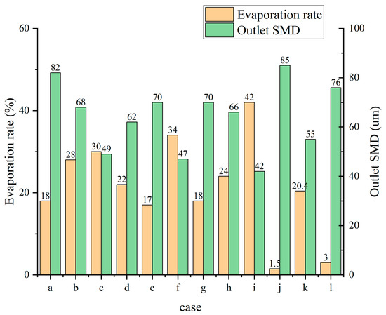
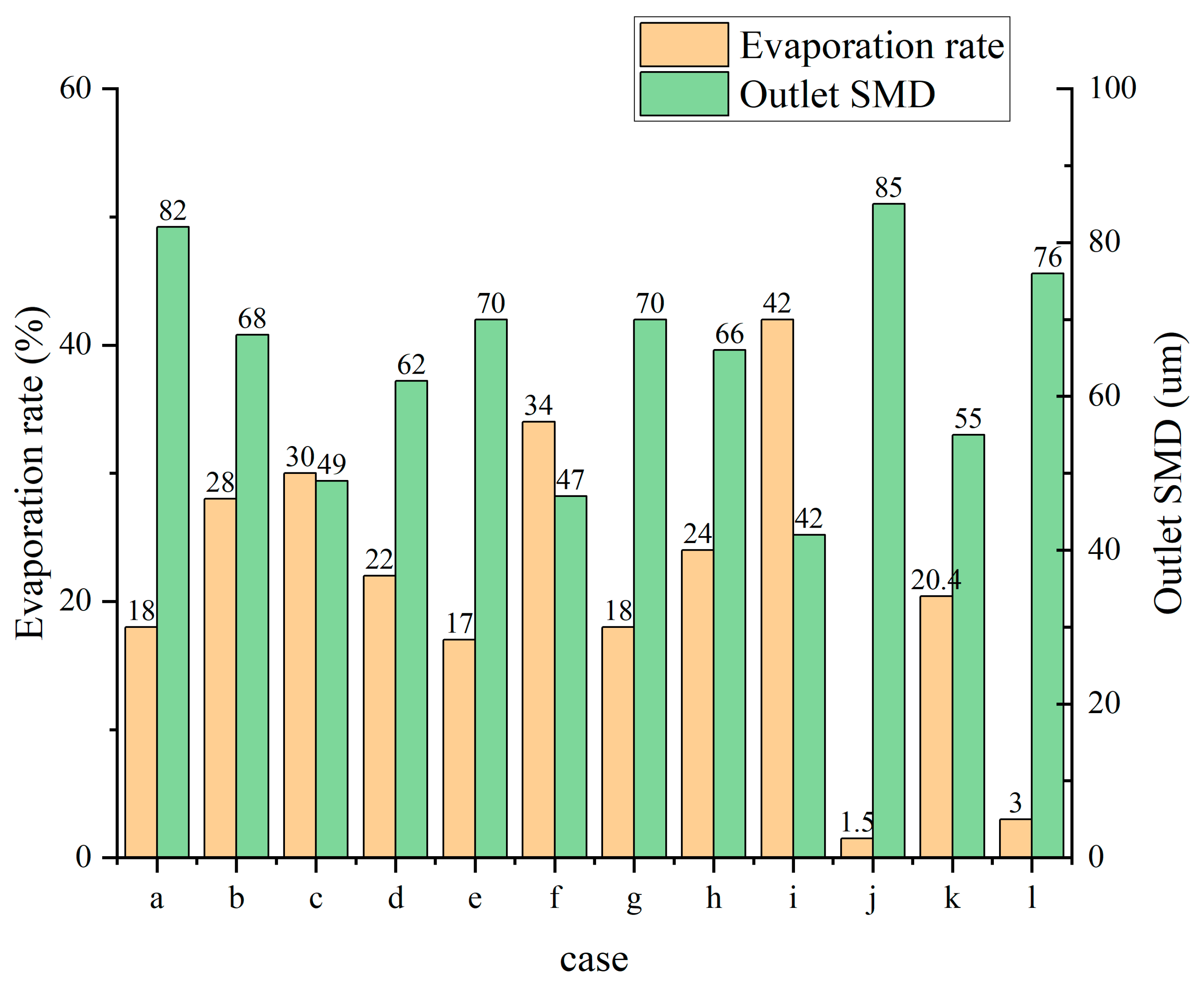
Figure 8 compares the outlet evaporation rate and SMD for all the cases. All the honeycomb-corrugated cases a~i outperform the conventional straight-tube Case j. Among all the cases, Case i has the highest evaporation rate and the lowest SMD, so this case is the best configuration. The comparison demonstrates that the proposed structure can improve evaporator tube performance and that an optimal geometric combination exists for the honeycomb-corrugated design.
Figure 8.
Comparison of outlet evaporation rate and SMD among all cases.
3.6. Performance of the Optimized Evaporator Tube Under Different Operating Conditions
To further investigate the operating characteristics of the optimized tube, Case i was selected for additional numerical simulations. For evaporator tube performance investigations, inlet temperature, air velocity, wall temperature, and air–fuel ratio are generally regarded as key operating factors. Because the inlet temperature was fixed by the boundary conditions used to represent the combustor environment, it was not treated as an independent variable. The following discussion therefore considers air–fuel ratio, inlet-air velocity, and wall temperature.
3.6.1. Influence of Air-Fuel Ratio on Fuel Evaporation and SMD
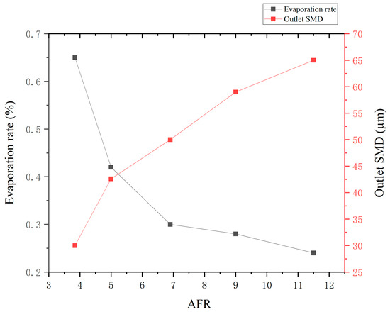
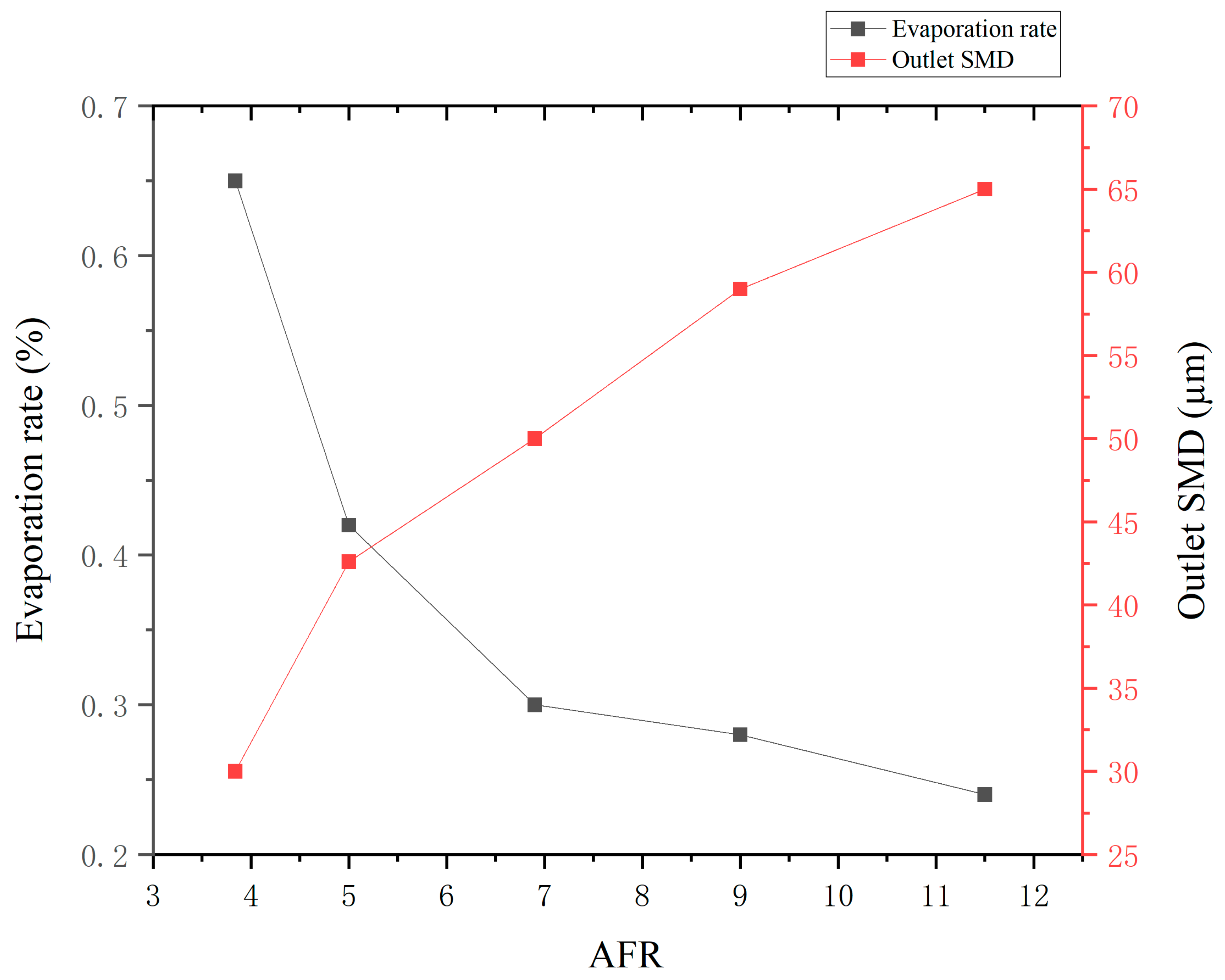
The air–fuel ratio was defined as , is the ratio of air mass flow and is the fuel mass flow, which was varied to evaluate the evaporation performance of Case i. The wall temperature was 800 K, the inlet-air temperature was 430 K, the inlet–outlet pressure difference was 8000 Pa, and the reference pressure was 290 kPa. The relationships of evaporation rate and SMD with air-fuel ratio is shown in Figure 9.
Figure 9.
Effect of air–fuel ratio on evaporation performance.
In these calculations, the inlet–outlet pressure difference in the evaporator tube was kept constant, so the air flow rate remained unchanged and only the fuel-injection flow rate was varied. AFR ranged from 3.84 to 11.5, corresponding to fuel flow rates from 0.222 to 0.666 g/s. This approach simulates non-uniform fuel distribution among tubes or fuel-supply fluctuations under realistic combustor operation. Figure 8 shows that, at constant air flow and air velocity, increasing AFR raises the evaporation rate and reduces outlet SMD. A higher AFR therefore strengthens evaporation mass transfer and improves fuel vaporization efficiency, highlighting the importance of an appropriate AFR for fuel preparation and subsequent combustor operation.
3.6.2. Influence of Inlet-Air Velocity on Fuel Evaporation and SMD
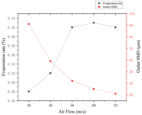
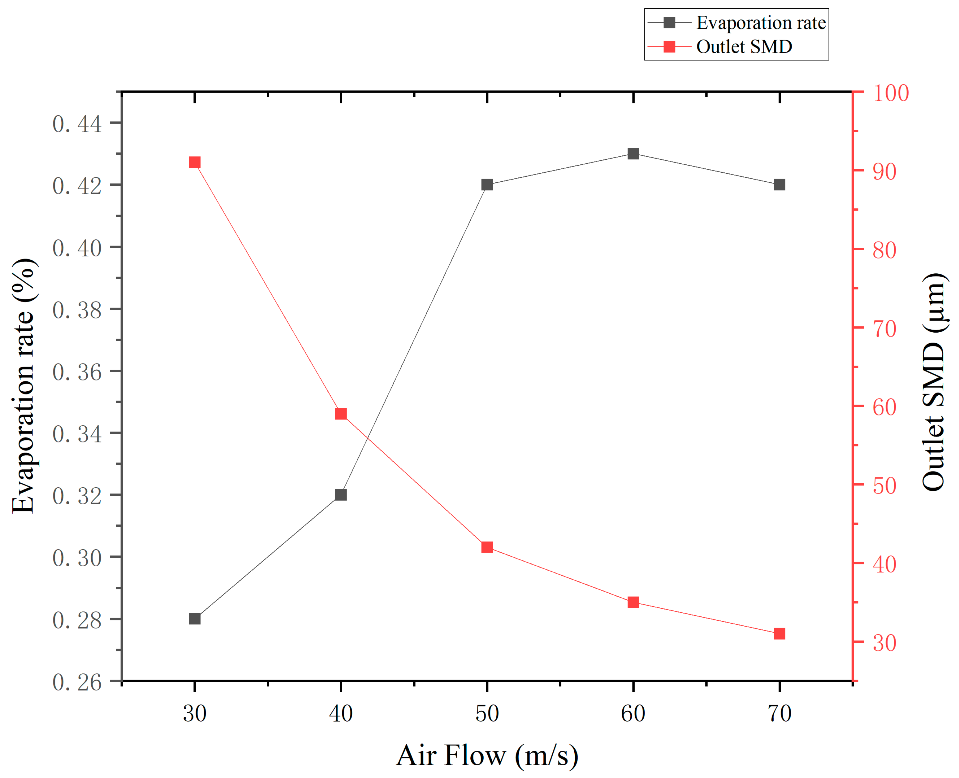
Inlet-air velocity was varied from 30 m/s to 70 m/s to evaluate its effect on the evaporation performance of Case i. The inlet-air temperature remained constant at 430 K, the fuel flow rate was fixed at 0.333 g/s, and the reference pressure was maintained at 290 kPa. The corresponding variations in evaporation rate and SMD are shown in Figure 10.
Figure 10.
Effect of inlet-air velocity on evaporation performance.
As inlet-air velocity increases from 30 m/s to 70 m/s, fuel atomization improves substantially and SMD decreases from 91 μm to 32 μm. The evaporation rate rises rapidly within the velocity range of 30~50 m/s. When the inlet-air velocity exceeds 60 m/s, atomization continues to be optimized, yet the residence time of droplets in the tube becomes shorter, slowing the growth of the evaporation rate. Therefore, an appropriately elevated inlet velocity should be adopted in combustor design, while guaranteeing sufficient droplet residence time for evaporation.
3.6.3. Influence of Wall Temperature on Fuel Evaporation and SMD
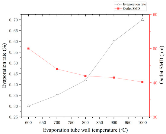
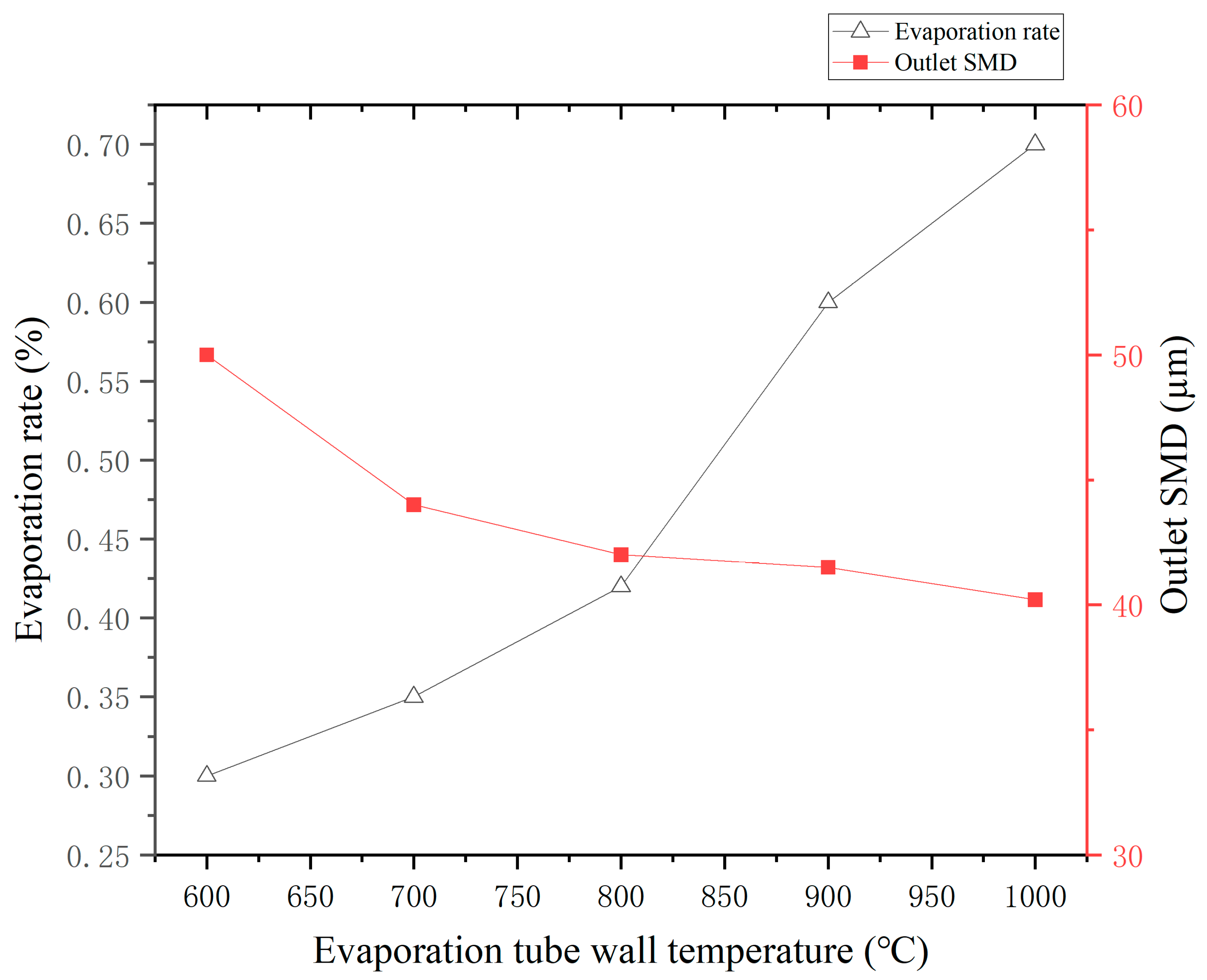
The wall temperature was varied from 600 K to 1000 K to evaluate its influence on Case i. The inlet–outlet air pressure difference was fixed at 8000 Pa, the inlet-air temperature remained 430 K, the fuel flow rate was 0.333 g/s, and the reference pressure was set to 290 kPa. The variations in evaporation rate and SMD with wall temperature are shown in Figure 11.
Figure 11.
Effect of wall temperature on evaporation performance.
As illustrated in Figure 11, the evaporation rate increases with increasing wall temperature, whereas outlet SMD decreases only slightly. This demonstrates that wall temperature exerts a significant impact on the evaporation rate yet imposes a limited effect on fuel atomization. Its effect on evaporation arises from two reasons. Firstly, increasing wall temperature raises the average air temperature in the tube. As wall temperature increases from 600 K to 1000 K, the outlet average air temperature increases from 466 K to 563 K, which intensifies thermal heating of droplets by the gas phase. Secondly, higher wall temperatures facilitate enhanced direct heat transfer to droplets impacting the heated wall. Compared with the conventional straight tube, the honeycomb-corrugated vaporizer tube achieves stronger convective heat transfer between the heated wall and airflow, rendering the effect of wall temperature on evaporation more remarkable. The slight variation in SMD implies that wall temperature barely alters the flow-field structure governing atomization.
3.7. Implications for Liquid-Fuel Combustion
The optimized honeycomb vaporizer tube enhances combustion preparation by simultaneously addressing the aerodynamic and thermal constraints governing liquid-fuel conversion. A reduction in outlet SMD increases droplet surface-area-to-volume ratio and shortens the characteristic heating and evaporation time, while the higher outlet gas temperature and more uniform cross-sectional temperature field raise the thermal readiness of the fuel–air mixture. Collectively, these effects can reduce liquid carryover into the primary zone, restrain wall wetting, and generate a more spatially uniform vapor-air mixture before ignition and flame propagation.
Furthermore, the results also reveal a practical design trade-off for liquid-fuel combustors. Increasing flow resistance alone is not beneficial, and maximizing air flow alone is also insufficient. Optimal combustion-preparation performance is achieved through a balanced combination of local shear, secondary flow, wall-contact heat transfer, and droplet residence time. Therefore, the optimized geometry provides a compact passive strategy for improving ignition reliability, flame stability, and combustion efficiency in micro-scale combustors without extra active atomization equipment.
4. Conclusions
This study combines a corrugated structure with honeycomb plates to develop a honeycomb-corrugated evaporator tube and investigates fuel atomization and evaporation inside the tube. The influence of geometric parameters on fuel atomization and evaporation efficiency is analyzed, leading to the following conclusions:
(1) The results of L9 (34) orthogonal analysis show that the geometric parameters exhibit distinct hierarchical effects on the fuel evaporation rate of the evaporator tube, with the influence magnitude ranked as corrugation height > honeycomb-plate layers > honeycomb-hole diameter > corrugation radius. The optimal parameter combination is determined as a corrugation height of 1 mm, three honeycomb plate layers, a honeycomb hole diameter of 0.6 mm, and a corrugation radius of 4 mm (Case i).
(2) The periodic contraction and expansion of the corrugated passage, together with the honeycomb plates, produce repeated local acceleration and deceleration, airflow redistribution, and recirculation within the tube. These flow-field characteristics promote radial heat and droplet transport and increase droplet interaction with the heated near-wall region. The resulting flow and temperature distributions are consistent with the higher evaporation rate and smaller outlet SMD obtained for the honeycomb-corrugated tube.
(3) Under the same boundary conditions, the optimized honeycomb-corrugated tube achieves remarkable improvements in fuel atomization and evaporation performance compared with the conventional straight tube. The fuel evaporation rate is greatly increased from 1.5% to 42%, the outlet SMD is reduced from 79.0 μm to 42.6 μm, and the average outlet-air temperature is elevated by 81 K. Although the composite structure causes a 31.6% reduction in air mass flow rate, the substantial enhancements in core atomization and evaporation performance fully demonstrate the technical superiority of the newly designed tube.
(4) Further parametric analysis of the optimal Case i indicates that increasing inlet-air velocity and air–fuel ratio (AFR) can effectively improve the comprehensive performance of the evaporator tube, characterized by improved evaporation efficiency and refined droplet atomization quality (reduced SMD). Tube wall temperature is identified as a critical thermodynamic parameter dominating the fuel evaporation process. Increasing the wall temperature from 600 K to 1000 K can significantly enhance the fuel evaporation rate, while it exerts a negligible effect on the outlet droplet SMD.
Author Contributions
Conceptualization, T.Z. and Z.W.; methodology, T.Z. and P.W.; software, P.W.; formal analysis, T.Z. and P.W.; investigation, P.W. and D.Z., resources, D.Z. and S.L.; data curation, T.Z. and P.W.; writing—original draft preparation, T.Z. and P.W.; writing—review and editing, T.Z. and P.W.; visualization, T.Z., S.L., B.L., W.L. and L.X.; supervision, Z.W.; project administration, T.Z. and Z.W.; funding acquisition, T.Z., Z.W., D.Z., S.L., B.L., W.L. and L.X. All authors have read and agreed to the published version of the manuscript.
Funding
This work was supported by the fundamental research funds for Liaoning province/[NO.2025JH2/101800305/NO.2026JH2/102700021]; and the Science and Technology Department project for Guangxi Zhuang Autonomous Region [NO. AA24263071/JF2503980005/AA24263077].
Institutional Review Board Statement
Not applicable.
Informed Consent Statement
Not applicable.
Data Availability Statement
The original contributions presented in this study are included in the manuscript. Further inquiries can be directed to the first author.
Conflicts of Interest
Authors Delin Zeng, Shengyou Liao, Weizhi Liang and Liang Xue, were employed by Guangxi Yuchai Machinery Co., Ltd., while Baoquan Liang was employed by Guangxi Yuchai Special Equipment Co., Ltd. The remaining authors declare that the research was conducted in the absence of any commercial or financial relationships that could be construed as a potential conflict of interest.
Abbreviations
The following abbreviations are used in this manuscript:
| MTEs | Micro Turbojet Engines |
| SMD | Sauter Mean Diameter |
| DPM | Discrete Phase Model |
| DOE | Orthogonal Design of Experiments |
| ARF | Air–Fuel Ratio |
References
- De Campos, A.P.V.; Sacomano Filho, F.L.; Krieger Filho, G.C. Design analysis of a micro gas turbine combustion chamber burning natural gas. In Proceedings of the ASME Turbo Expo 2012: Turbine Technical Conference and Exposition, Copenhagen, Denmark, 11–15 June 2012. [Google Scholar] [CrossRef] [Scilit]
- Çatori, C.; Topal, A.; Uslu, S.; Tuncer, O.; Çağan, L.; Özkan, S.A.; Kaynaroğlu, B.; Çelik, E. Exit temperature profile measurement and CFD comparisons on small-scale turbojet combustor with air-blast atomizer configuration. In Proceedings of the 50th AIAA/ASME/SAE/ASEE Joint Propulsion Conference, Cleveland, OH, USA, 28–30 July 2014. [Google Scholar] [CrossRef] [Scilit]
- Yang, C.; Wu, H.; Du, J.; Zhang, H.; Yang, J. Full-engine simulation of micro gas turbine based on time-marching throughflow method. Appl. Therm. Eng. 2022, 217, 119213. [Google Scholar] [CrossRef] [Scilit]
- De Paepe, W.; Montero Carrero, M.; Bram, S.; Parente, A.; Contino, F. Toward higher micro gas turbine efficiency and flexibility—Humidified micro gas turbines: A review. J. Eng. Gas Turbines Power 2018, 140, 081702. [Google Scholar] [CrossRef] [Scilit]
- Xie, Z. Development and application promotion of micro gas turbines in China at the current stage. Sci. Technol. Innov. 2018, 8, 160–161. [Google Scholar]
- Mao, L. Application of micro gas turbines in distributed energy supply. Intern. Combust. Engine Parts 2017, 19, 99. [Google Scholar]
- Xie, Z.; Zhao, Z. Simulation analysis of micro gas turbine operation fueled by biomass gas. Energy Conserv. 2018, 37, 21–24. [Google Scholar]
- Kulshreshtha, D.B.; Channiwala, S.A. Design and Development of Combustion Chamber for Small Gas Turbine Power Plant; SAE Technical Paper 2005-26-317; SAE International: Warrendale, PA, USA, 2005. [Google Scholar] [CrossRef] [Scilit]
- Nonnenmacher, S.; Piesche, M. Design of hollow cone pressure swirl nozzles to atomize Newtonian fluids. Chem. Eng. Sci. 2000, 55, 4339–4348. [Google Scholar] [CrossRef] [Scilit]
- Saddawi, S.D.; Kipouros, T.; Savill, M. Computational engineering design for micro-scale combustion devices: A thermally improved configuration. In Proceedings of the ASME Turbo Expo 2013: Turbine Technical Conference and Exposition, San Antonio, TX, USA, 3–7 June 2013. [Google Scholar] [CrossRef] [Scilit]
- Zhang, Y.; Tian, Y.; Le, J. Review of atomization characteristics of liquid jets in crossflow. Phys. Fluids 2024, 36, 021302. [Google Scholar] [CrossRef] [Scilit]
- Zhou, D.; Chang, J.; Shan, H. Investigations of the atomization characteristics and mechanisms of liquid jets in supersonic crossflow. Aerospace 2023, 10, 995. [Google Scholar] [CrossRef] [Scilit]
- Abedinejad, M.S. Analysis of spray evaporation in a model evaporating chamber: Effect of air swirl. J. Therm. Sci. 2023, 32, 837–853. [Google Scholar] [CrossRef] [Scilit]
- Kim, J.C.; Yoo, E.; Sung, H.G. Influence of liquid-fuel swirl injection pressure on the flow dynamics characteristics in a lean direct injection gas turbine combustor using Eulerian–Lagrangian large eddy simulations. J. Mech. Sci. Technol. 2024, 38, 691–701. [Google Scholar] [CrossRef] [Scilit]
- Akerblom, A.; Fureby, C. LES modeling of the DLR generic single-cup spray combustor: Validation and the impact of combustion chemistry. Flow Turbul. Combust. 2024, 112, 557–585. [Google Scholar] [CrossRef] [Scilit]
- Ghiyasi, M.; Bazdidi-Tehrani, F. Turbulence–radiation interaction effects on liquid fuel droplet evaporation in spraying combustion flow using large eddy simulation. Flow Turbul. Combust. 2025, 114, 323–358. [Google Scholar] [CrossRef] [Scilit]
- Cavalieri, D.; Liberatori, J.; Blandino, M. Evaluation of non-ideal fluid modeling for droplet evaporation in jet-engine-like conditions. Flow Turbul. Combust. 2025, 114, 857–885. [Google Scholar] [CrossRef] [Scilit]
- Yang, X.; Fan, W.; Huang, X.; Zhang, R. Influence of evaporation tube scheme on the flow field and combustion characteristics in a micro gas turbine combustor. Propuls. Energy 2025, 1, 17. [Google Scholar] [CrossRef] [Scilit]
- Gong, C.; Zhao, S.; Chen, W.; Li, W.; Zhou, Y.; Qiu, M. Numerical study on the combustion process in a gas turbine combustor with different reference velocities. Adv. Aerodyn. 2023, 5, 24. [Google Scholar] [CrossRef] [Scilit]
- Fu, Y.; Lin, H.; Yu, J.; Song, A.; Guo, Q.; Wen, Z.; Wu, W. Study on influence of evaporation tube flow distribution on combustion characteristics of micro combustion chamber. Processes 2025, 13, 1691. [Google Scholar] [CrossRef] [Scilit]
- Zhu, J.; Guo, X.; Lin, Y.; Ma, H. Experimental study on evaporation rate of micro T-type vaporizer tubes. J. Aerosp. Power 2007, 22, 1273–1278. [Google Scholar]
- Lin, Y.; Liu, J.; Xu, Q.; Guo, X. Evaporation rate of a micro Gamma-type vaporizer tube under atmospheric pressure. J. Aerosp. Power 2006, 21, 843–847. [Google Scholar]
- Qin, W.; Fan, W.; Zhang, T.; Yan, P. Performance test of vaporizer tubes and numerical simulation of a combustor in a micro turbojet engine. J. Aerosp. Power 2012, 27, 861–867. [Google Scholar]
- Olivier, A.J. An Experimental and Numerical Investigation of Vaporizer Tubes Associated with Micro Gas Turbines. Ph.D. Thesis, Stellenbosch University, Stellenbosch, South Africa, 2015. [Google Scholar]
- Zhou, Q. Research on a New Vaporizer Tube and Its Application in a Micro Combustor. Master’s Thesis, Nanjing University of Aeronautics and Astronautics, Nanjing, China, 2009. [Google Scholar]
- Wei, C. Design and Research of Advanced Combustor for Micro Aeroengines. Master’s Thesis, Harbin Institute of Technology, Harbin, China, 2019. [Google Scholar]
- Zhang, X.; Zhang, Q.; Li, G.; Hu, J. Numerical study on atomization characteristics of biomimetic evaporation tube in micro turbine engine. iScience 2024, 27, 109144. [Google Scholar] [CrossRef] [Scilit]
- Zhang, Q.; Zhang, X.; Hu, J.; Li, G. Research on the heat transfer characteristics of evaporator tubes in micro turbine engines based on biomimetic parallel leaf vein structure. Sci. Rep. 2025, 15, 30574. [Google Scholar] [CrossRef] [Scilit] [PubMed]
- Fagbade, A.; Heinz, S. Continuous Eddy Simulation vs. Resolution-Imposing Simulation Methods for Turbulent Flows. Fluids 2024, 9, 22. [Google Scholar] [CrossRef] [Scilit]
- Liu, L.; Ahmed, U.; Chakraborty, N. A Comprehensive Evaluation of Turbulence Models for Predicting Heat Transfer in Turbulent Channel Flow across Various Prandtl Number Regimes. Fluids 2024, 9, 42. [Google Scholar] [CrossRef] [Scilit]
- Wang, L.; Jiang, L.J.; Xu, J.Q.; Qiu, S.H.; Xu, B.L.; Xie, L.C. Effects of evaporator tube length on fuel atomization and evaporation characteristics. J. Propuls. Technol. 2026, 1–10. Available online: https://link.cnki.net/urlid/11.1813.V.20260129.1504.003 (accessed on 27 August 2026).

Disclaimer/Publisher’s Note: The statements, opinions and data contained in all publications are solely those of the individual author(s) and contributor(s) and not of MDPI and/or the editor(s). MDPI and/or the editor(s) disclaim responsibility for any injury to people or property resulting from any ideas, methods, instructions or products referred to in the content. |
© 2026 by the authors. Licensee MDPI, Basel, Switzerland. This article is an open access article distributed under the terms and conditions of the Creative Commons Attribution (CC BY) license.