


Abstract
In stirred tank reactors, especially without using baffles, the liquid surface can deform, which in stirring technology is referred to a vortex. These vortices can be advantageous for some mixing tasks, such as obtaining emulsions, they can also impair a consistent product quality. Therefore, it is important for the production and process industry, to know whether a vortex occurs or not. Prediction is only possible with an outdated dimensionless baffle index and research on vortex formation with baffles is limited. In this study, two industrially important axial stirring systems—Propeller and Pitched-blade turbine—with different baffle geometries (rectangular, cylindrical, triangular) and numbers are assessed in regard to power input, vortex characteristics (depth, width, volume) and baffle state prediction. Power is recorded using strain gauges, while vortices are evaluated using an optical image evaluation method. The final vortex result is made dimensionless, accessible to the industry to enable improved predictions about the size of the vortices on an industrial scale in order to make the stirred tanks more economical and sustainable. Furthermore, an initial improvement of the baffle index for the investigated stirrers is given, because the original index incorrectly predicts the baffle state in 12.5% of cases.
1. Introduction
According to the literature [1,2], vortices in stirred tank reactors occur in single-stage stirring systems without the use of baffles. These vortices can be disruptive, for example, with regard to homogenization reaction mixtures or heat exchange [3] and may damage the stirring drive unit [1,2]. But, they also have advantages, for example, to get floating particles into a reaction system [4] or to obtain a complete and stable emulsion [5]. Installing baffles prevents these vortices because the baffles break up the tangential flow component and convert it into a radial or axial flow in a targeted manner [1,2,6,7,8,9].
Whether a vortex forms or not is nowadays determined using an outdated, dimensionless baffle index number, proposed by Liepe et al. [6]. This dimensionless baffle index concept involves the following two equations.
Equation (1) for the calculation of the “dimensionless baffle index” BW includes the appearance of the baffles (shape cF, width bS, immersion depth HS,eff) as well as the configuration of the reactor (reactor inner diameter D, number of baffles N). The value 0.8 describes the wake effects of the baffle and is, according to Liepe et al. [6], assumed to be the same for each type of baffle [6].
Equation (2) is additionally used to compute the “dimensionless fully baffled index” BWvb. This number takes into account some agitator characteristics and includes the stirrer diameter (dR) and the Newton number (Ne). The value 0.36 seems to be a hypothetical value of an origin that is not further described in the literature [6].
If Equation (2) delivers a higher value than Equation (1) (BW < BWvb) the whole system is considered as partly baffled or unbaffled and therefore vortices are supposed to occur. However, if the value obtained from Equation (1) is bigger than that from Equation (2), a fully baffled system is assumed, implying the absence of vortices. This means that in this case only slight surface turbulences with or without air entry should be found. This statement is supported when BW ≥ 0.2, while the further literature [1,2] predicts fully baffled state with four baffles with a width of D/10 and a wall distance of D/50 [6].
The knowledge about vortices from scientific studies is very limited. There have been only a few studies about the formation and the appearance of the vortices and they are based almost exclusively on radial stirring systems with unvalidated simulation results [10,11] or experimental results without baffles [3,12,13,14,15,16], in which only the vortex depth (cf. Figure 3 right side) is dealt with, or the coupled simulation and experimental results [4,17,18,19]. A comprehensive experimental description of vortices, including width and volume (cf. Figure 3 right side), as well as with the use of baffles has so far only been carried out by the research group of Schultz [20,21,22,23,24,25].
Even though vortices are usually initially associated with radially acting stirrers, the tangential flow component of axial stirrers are often underestimated [26], which is incorrect and can lead to incorrect designs of stirred tank reactors. Therefore, the data available on axial stirring systems, which also have important relevance and application in industrial reactors, has not yet been sufficiently investigated in regard to vortex formation with baffles. Investigations found in the field of vortex formation often deal with the stirring elements Propeller and Pitched-blade turbine. However, in these literature data only the vortex depth is assessed when using no baffles, like with radial stirring systems [3,4,12,13,14].
Three studies dealing with vortex formation are particularly noteworthy, as they largely use the same stirrers and geometric properties as in this study. In the investigation by Karcz et al. [27], a flat-bottom reactor (H = D = 0.6 m) with the Propeller, three-blade Pitched-blade turbine and Rushton turbine (dR = 1/3D and installation height hR = 1/3D) is experimentally investigated in combination with different lengths, numbers and positions of four planar baffles with a width of D/10. With regard to the formation of vortices, however, only a statement when a vortex occurs or not was made, and whether the vortex is advantageous or disadvantageous for the fate of floating particles has been a specific objective of that study.
The investigation by Komarov et al. [4] also deals with floating particles and investigates the resulting vortices experimentally and numerically using Computational Fluid Dynamics (CFD). A flat-bottom reactor (D = 94 mm) with a Pitched-blade turbine (dR = 50 mm, hR = 80 mm) without a baffle was used. In that publication, only the vortex depth is considered too, as it is relevant for the particle entry into the liquid.
The last investigation that should be highlighted deals with the prediction of whether a vortex occurs or not. Heyter et al. [28] looked at a 45° four-blade Pitched-blade turbine (dR = 0.605D, hR = 0.33–1.92) and a Rushton turbine (dR = 1/3D, hR = 1/5D) in a dished-bottom reactor (D = 400 mm, H/D = 1–1.5). Rectangular baffles are used with a width of bS = 0.08D and D/10 in the numbers of one to four. The baffles are attached in the angles of 60 and 90 with a bottom distance of D/5 and a wall distance of D/50. For a single-stage Pitched-blade turbine, it was found that the Pitched-blade turbine is fully baffled with a dimensionless baffle index of 0.24.
There is consequently a knowledge gap in the description and prediction of vortices, which has only recently begun to be addressed in more detail. In particular, this contribution aims to focus and discuss the previously insufficient or missing investigations of axially stirred systems. The aim of this work is therefore a comprehensive investigation of the power input and the vortex characteristics (depth, width and volume) in single-stage axial stirring reactors with the Propeller and Pitched-blade turbine. In addition, the prediction of the vortices with different baffle geometries and numbers as well as without baffles is considered. Above that, the latest vortex results determined are presented in a transparent manner for the production and process industry in order to enable the design of more sustainable reactors with better implementation of level measurements, etc.
2. Materials and Methods
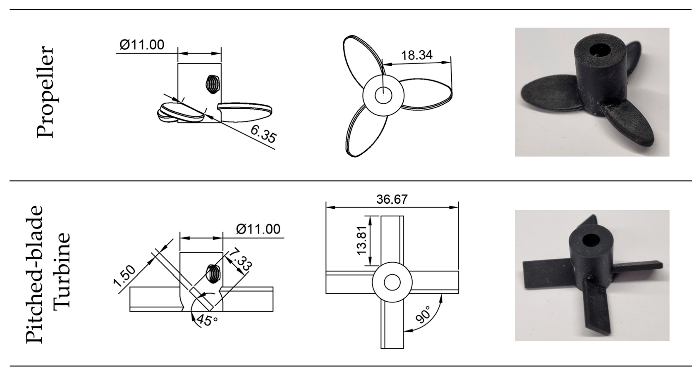
The investigations of the power input and vortex characteristics were carried out with 3D-printed Propeller (PR) and Pitched-blade turbine (PBT) stirrers (see Figure 1), manufactured according to DIN 28131 [29]. Both parameters, the diameter of the stirrers dR = D/3 and the installation height hR = D/3, were defined in relation to the reactor inner diameter D. The stirrer was attached to the stirrer shaft in a practical manner with the help of a Marden screw [30]. The used flat-bottom reactor was made of polymethyl methacrylate (PMMA) (D = 110 mm, wall thickness w = 5 mm, H = D, with H = liquid filling height) and the fluid used was water 22 °C ( 998.21 kg/m3, = 1.003∙10−6 m2/s).
Figure 1.
Used stirrers, dimensions given in [mm]. Left: Geometric properties, side view. Middle: Geometric properties, top view. Right: Photograph of the used 3D-printed stirrers. Figure inspired by [31].
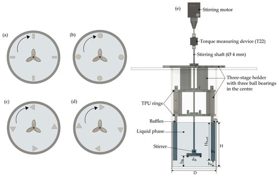
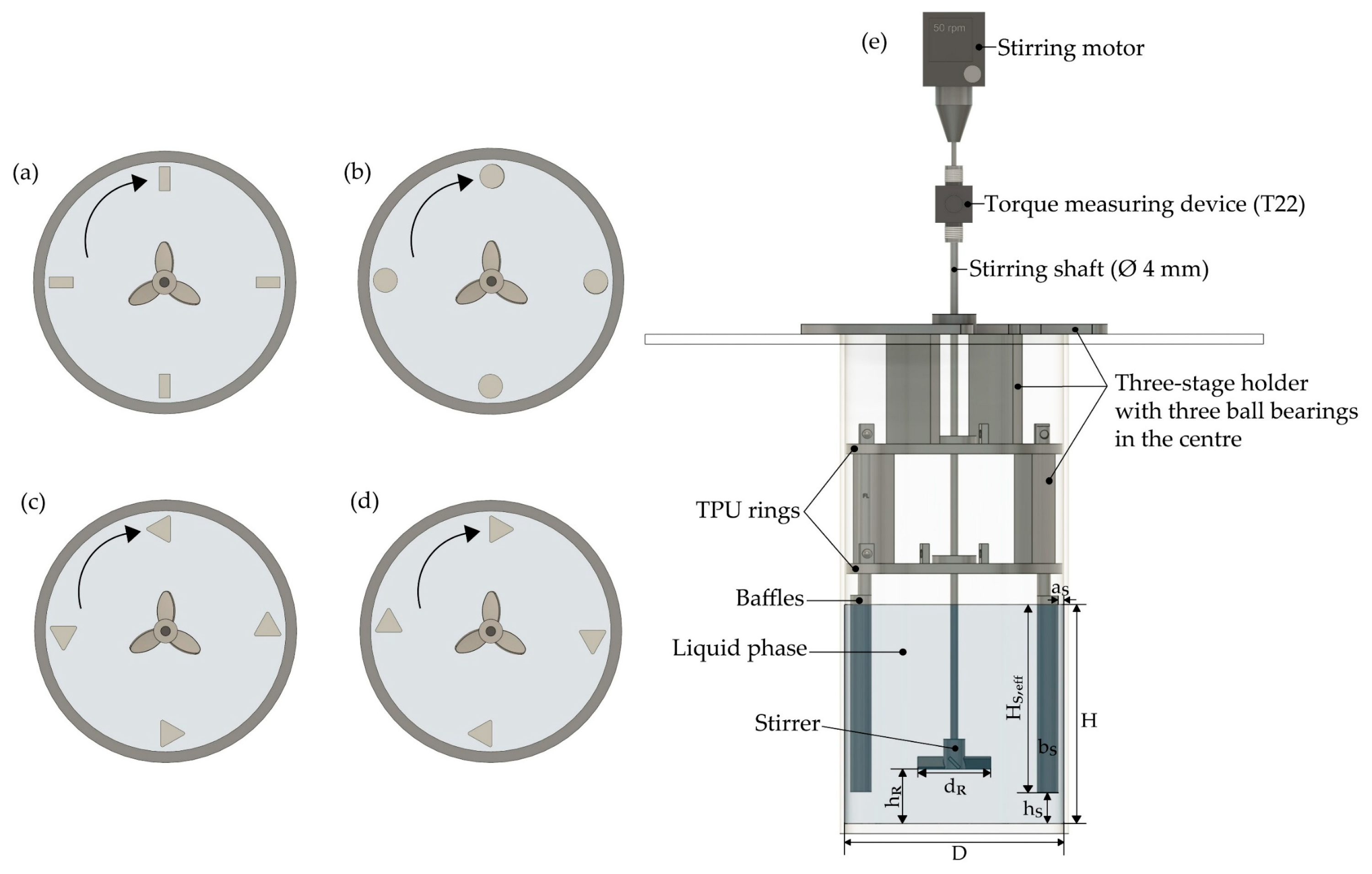
In addition to measurements without baffles, different types and numbers (one to six) of 3D-printed baffles were examined in the width (bS = D/10) and wall distance (aS = D/50) designed according to the DIN standard (see Table 1) [29]. The types of baffles examined were rectangular, cylindrical and triangle baffles. In the case of triangle baffles, the flow hit the tip in the first, or the plane side in the second measurement series. The flow towards the different types of baffles is marked with an arrow in Figure 2a–d. The baffles were mounted using a three-stage 3D-printed holder device made of polylactic acid (PLA) (see Figure 2e) with rivet bodies so that both the average distance of the baffles to the reactor bottom (hS) from the literature and the wall distance according to the DIN standard [29] were observed. The immersed length of the baffles (HS,eff) was grinded and painted with a clear coat for optical measurement purposes, making the dimensions and ends of the vortices visible as well.
Table 1.
Dimensions of the used baffles and shape effects of the different baffle geometries.
Figure 2.
Flow towards (a) rectangular, (b) cylindrical, (c) triangle tip, (d) triangle plane baffles. (e) Exemplary sketch of the stirring set-up without PMMA aquarium around the reactor.
Furthermore, thermoplastic polyurethane (TPU) rings (see Figure 2e) were attached around the holder so that the holder was strictly fixed in the reactor and the baffles did not move or even rotate while stirring. There was a ball bearing on each step in the middle of the holder construction to ensure that the stirrer shaft was installed and held in the middle.
The reactor with baffle holder device and stirrer was additionally placed in a PMMA aquarium filled with water, to eliminate light reflections on curved surfaces. The stirring shaft was painted black and attached to the T22 torque measuring device (measurement accuracy of 0.5%) from Hottinger Brüel & Kjaer (Darmstadt, Germany), which was mounted accordingly on the Microstar 7.5 digital stirring motor from IKA, Staufen im Breisgau, Germany (range 50 to 2000 rpm). The power input was determined from 3000 torque measurements, which were generated in 30 s via strain gauges. The torque measuring device was calibrated in still water and the measurement was carried out by increasing the speed in 50 rpm steps until there was a strong entry of gas into the water.
The vortices were observed and measured with the Canon EOS 600D camera, Tokyo, Japan (with EF-S 18–55 mm lens; exposure time 1/60, aperture 5.6, focal length 18 mm). The resulting vortices were illuminated with an LED (Veritas truth in light) and a black 3D-printed background in the PMMA aquarium improved the contrast. Before each measurement, a calibration photo was taken with graph paper within the reactor so that every measurement had an individual conversion factor of pixel/mm. With this conversion factor it was possible to describe the vortices in mm during the evaluation. The vortices were measured after calibration with 8-second videos (24 fps, 192 images) for each rotational frequency.
2.1. Evaluation of the Experimental Torque Measurements
To determine the power input for the stirred reactor, the results of the 3000 torque measurements were averaged and used to calculate the Newton number (see Equation (3)). To determine the power characteristics, the Reynolds number was also determined using Equation (4). The values of the Newton and Reynolds numbers were then plotted double logarithmically in a diagram. In both equations, the rotational frequency was converted from rpm to rps by a factor of 60 [25].
2.2. Determination of the Vortex Characteristics
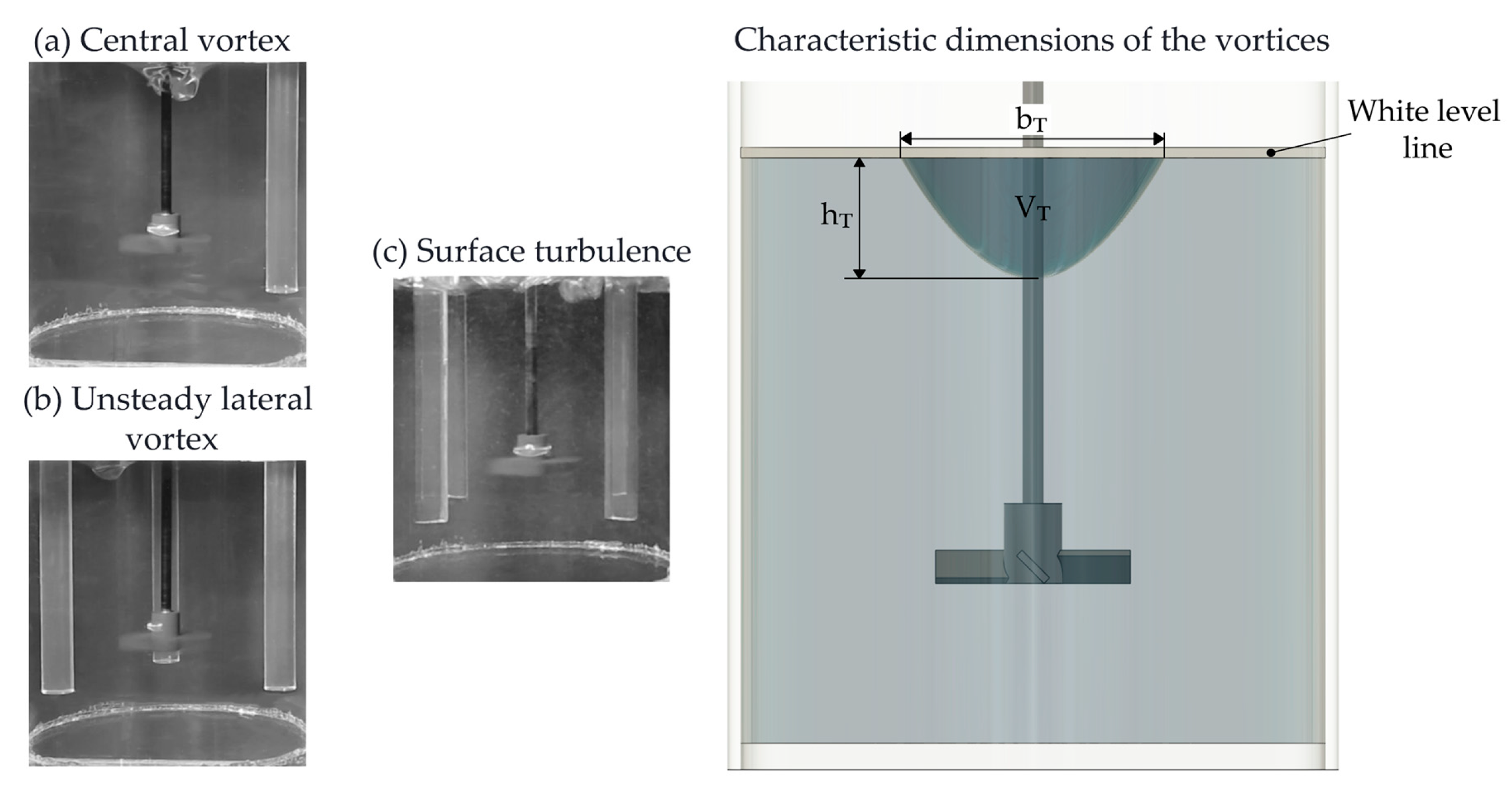
In the literature [1,2,6], vortices are described as deformation of the liquid surface. It is not described exactly when this phenomenon should be called a vortex. Furthermore, the literature only speaks of vortices that cause the liquid to deepen on the stirring shaft. With the diverse measurements in this study, however, it was possible to determine that there were not only central vortices (see Figure 3a left) but also unsteady lateral vortices were seen (see Figure 3b left). In addition to these two variants of vortices, surface turbulence was also shown (see Figure 3c left), which is the wavy movement of the surface without creating a distinct vortex in the liquid. The number of baffles in these three pictures differs because only one of the three existing phenomena can occur at any given time.
Due to the lack of available definitions in the literature, the selected criteria for classifying the vortex characteristics in this study are based on operational experience and contributions from partner companies. These criteria are consistent with own findings from practical mixing experience on various scales, in reactors with volumes of 100 m3 or more. Thus, a vortex is defined as a central vortex if they have the dimensions of 0.1% referring to the liquid reactor volume as vortex volume (VT) [25]. If this volume is reached after step-wise increasing stirring speed, evaluations of changes are carried out at 100 rpm intervals. For an industrial reactor volume of 50 m3, this already corresponds to 50 L, which increases further as the rotational frequency increases and means high mechanical stress on the stirrer drive unit.
Unsteady lateral vortices are referred to as a vortex starting from a volume of 0.05% referring to the liquid reactor volume [25], since this shape and behavior of the vortex leads to air entry very early. When the vortices reach this volume, they are evaluated again every 100 rpm, in the same way as the central vortices.
Figure 3.
(Left side): Possible surface phenomena (central vortex, unsteady lateral vortex, surface turbulence). (Right side): Characteristic dimensions of a vortex.
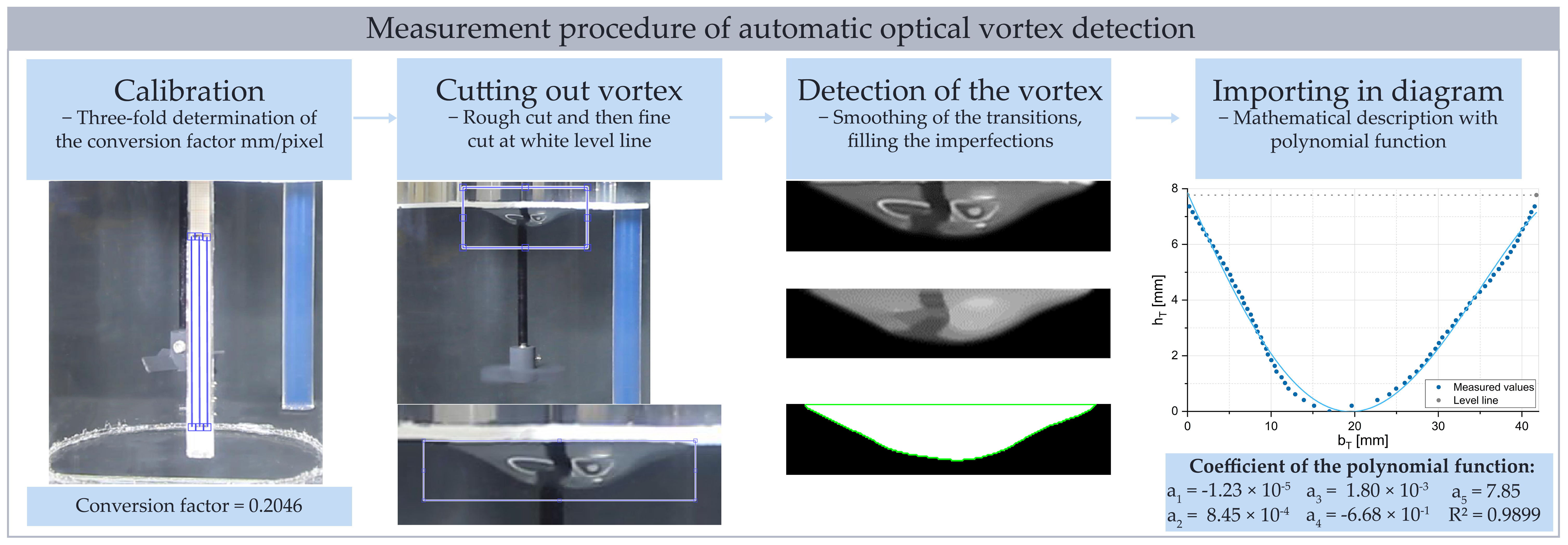
The vortices found were evaluated using MATLAB® (version R2022b) macros [24]. To do this, at first a calibration is carried out using graph paper in order to describe the dimension of the vortices in millimeter and not in pixels. Then the vortex videos are cut and in the next step, the vortex is cut roughly and then finely at the original unstirred level line and the recognized dimensions are identified by smoothing functions and converted into an x-y diagram. The evaluation algorithm can be seen as an example in Figure 4 and the following results are given as in the literature [1,33,34] on the unstirred level line.
Many mathematical functions (polynomial functions two- to fourth-degree, sine and cosine functions, exponential functions and normal distribution functions) to describe the vortices have already been tested in preliminary work, and it has been shown that the fourth-degree polynomial function (cf. Equation (5)) reflects the vortex data very well, achieving the best coefficient of determination.
With the help of this polynomial function, the vortex width (bT, cf. Figure 3 right side) is determined by calculating it with regard to the unstirred level line (linear function) and determining the intersection points. The vortex depth (hT, cf. Figure 3 right side) is analyzed using the first derivative of the polynomial function by assigning the zero point and then inserting the point in the polynomial and linear function. The results of the polynomial and linear function are then added together to the vortex depth. With the specified low point value, the curve is shifted to the origin (0/0) by subtracting the original bT values with the low point value. The values of hT are the same, so the vortex is only shifted on the x axis. With this curve, the vortex volume is determined by a new polynomial function, which is integrated with the rotational integral around the y-axis and the trapezoidal integration (see Equation (6)). For the rotational integral, the first derivation of the new polynomial function (hT′) must be calculated [25].
As part of a worst-case assessment, the four largest vortices were selected from the recorded 8-second videos and analyzed. From the four analyzed vortices, the mean values and standard deviations in terms of depth, width and volume were evaluated for each rotational frequency and are presented in Section 3.2. Evaluation of more than four vortices did not lead to any significant changes with regard to the examined vortex characteristics. It can generally be observed that the central vortex exhibited fairly stationary behavior with few fluctuations, which is why the error bars shown are small. Using random vortices did not lead to any significant changes either. In the case of the unsteady lateral vortices, there were more fluctuations due to their fluctuating nature of this vortex, which is why the error bars shown are slightly larger, but still within reasonable limits.
Figure 4.
Exemplary evaluation of a vortex with a pitched-blade turbine and one cylindrical baffle at ReR ≈ 12,000.
3. Results and Discussion
3.1. Power Measurements
The different reactor systems require different power inputs. This is important for the reactor design and also plays a role in predicting vortices (cf. Equation (2)). For this reason, the data from 3000 torque measurements, which are recorded via the strain gauges measuring device, are averaged and the Newton number is calculated using Equation (3). In addition to determining the power, the flow behavior is also evaluated using the Reynolds number (see Equation (4)) and is presented as a power characteristic by plotting the Re and the Ne numbers in a double logarithmic diagram.
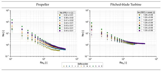
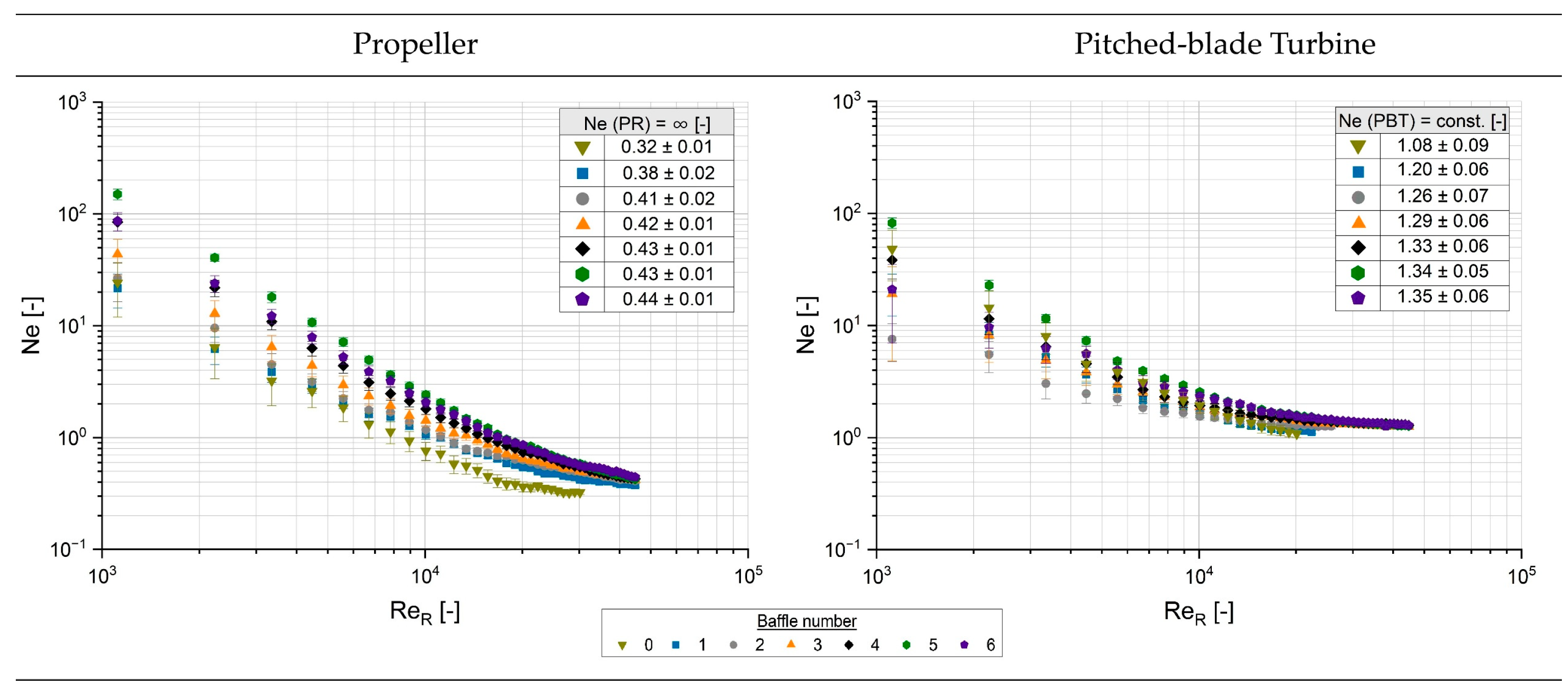
Figure 5 shows two examples of such a power characteristic diagram for the two stirrers examined with different numbers of rectangular baffles and without baffles. The results for the Propeller are shown on the left side, while those for the Pitched-blade turbine are shown on the right side. The same color represents the same number of baffles for both stirrers.
Figure 5.
Power characteristics of PR (left side) und PBT (right side) with no baffles and with one to six rectangular baffles.
At first view it is noticeable that the power input of the Pitched-blade turbine is higher than that of the Propeller and that installing baffles increases the power. In addition, it can be seen that the power characteristics for the Propeller increase with the number of baffles but they continue to decrease in the turbulent Reynolds number range (Re > 104). The curves for the Pitched-blade turbine with baffles turn constant in this turbulent area and also increase with the number of baffles. Furthermore, in the turbulent area the error bars, i.e., the standard deviations, become increasingly smaller for both stirring systems, which is significant because the fully turbulent case is particularly relevant for industrial applications, while the laminar case can often be neglected.
The definition of the “final” Newton numbers (cf. table in Figure 5) is taken from the last measured value for the Propeller, because the curves do not reach a constant range (Ne = ∞). For the Pitched-blade turbine, a value is determined from the constant range (Ne = const.) or, if there are no baffles, from the last value as this curve decreases like the Propeller curves too. When looking at the data (cf. table in Figure 5), it seems that although the values increase for both stirrers, they do not show a significant change from four baffles onwards within the limits of measurement accuracy. Furthermore, it should be noted that the measurements were stopped at the last evaluated vortex (cf. Figure 8) or when there was only minimal gas entry. The Newton numbers shown therefore correspond to those of the plateau in the turbulent range of the power characteristics before vortex formation and the associated gas entry, which subsequently changes the overall fluid density and viscosity and leads to a kink in the power characteristic as a result of the gas entry [25].
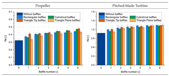
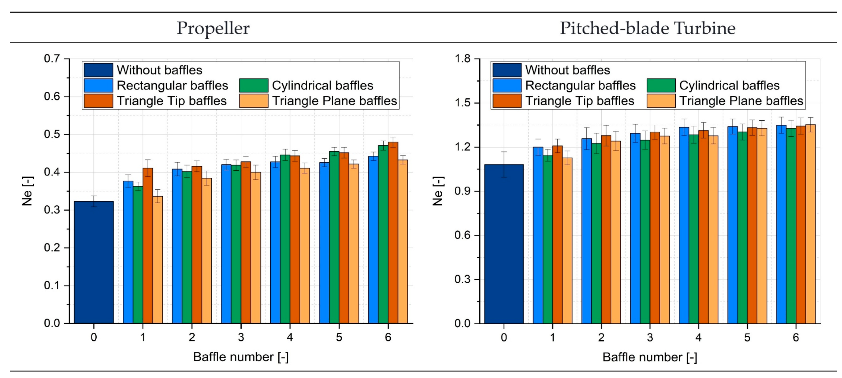
The calculated Ne values for both stirrers and the various baffle geometries and numbers are shown as bar charts with the corresponding standard deviation in Figure 6. If the error bars are not considered for now, it can be seen that the power for both stirrers is lowest without the use of baffles, which is due to the fact that these systems have no relevant flow resistance, resulting in lower power consumption than in case of baffle-usage. With baffles, a minimal increase in power can be seen for each stirrer, depending on the type and number of baffles.
Figure 6.
Calculated Ne values with standard deviations as error bars. (Left): Propeller (without baffles: Re ≈ 30,000 and with baffles Re > 29,000). (Right): Pitched-blade turbine (without baffles: Re ≈ 20,000 and with baffles Re > between 17,000 and 42,000).
Excluding the error bars, it can be seen that for the Propeller the triangular tip baffles require the highest power input and the triangular plane baffles the lowest. In the case of the Pitched-blade turbine, the rectangular baffles require the highest power input and the cylindrical baffles the lowest. Taking the error bars into account, these differences cannot be identified precisely anymore. So the interpretation above is qualitative here.
When the determined Ne values are compared with the literature data presented in Table 2, it can be seen that the value for the Propeller without a baffle is higher than the one in the literature. This could be due to the different measurement technologies used, or because the literature does not use a completely flat bottom reactor. If the values for the Propeller with baffles are compared with the literature values, it can be noticed that they are within the range of the literature data or are even higher. This could possibly be due to the fact that not all of the literature specifies the design of the stirrer, the installation height, the measured fluid or the type and number of baffles. It is clearly a drawback that many literature sources [1,2,33] in the past provide inadequate system descriptions, which is why comparability is rarely given. This work aims to change that, and therefore the system configurations are described in a transparent manner so that they can be used as a reference.
For the Pitched-blade turbine without baffles, the literature value presented is a little bit lower than that found in this study. However, the values with baffles are within the range of the available literature data. Again, it should also be noted that many publications [33,35,36,37] are not transparent and therefore not fully comparable with this study in terms of stirring design, baffle type and number, fluid and reactor design and measurement technology.
Table 2.
Newton number (Ne) data of the used stirrers from the literature.
If the determined Ne data are calculated with help of Equation (2) using the corresponding stirrer diameter and reactor diameter from Section 2 (see Figure 1) and compared with the BW values (Equation (1) with the values from Table 1), the following theoretical predictions for vortex formation are found (see Table 3). In Table 3, a “+“ sign represents surface turbulence, while a “−“ sign means appearing vortices. Not included in this table is the system without a baffle, because in that case BW = 0 and thus BWvb is always higher and therefore vortices will always be present according to the theoretical prediction.
Table 3.
Theoretical prediction (+ Surface turbulence; − Vortex) according to Liepe [6] with dimensionless baffle index (BW) and experimental Ne values obtained from data shown in Figure 6.
Table 3 thus theoretically states that most cases of vortex formation should be found with both types of stirrers with cylindrical baffles (PR approx. 50%; PBT approx. 83%), while the rectangular baffles are expected to have the lowest number of cases (PR approx. 17%; PBT approx. 17%). With triangular baffles, the Propeller with one baffle (tip and plane approx. 17%) should produce vortices, while the Pitched-blade turbine should also produce vortices with two triangular baffles (tip and plane approx. 33%). In summary, Table 3 shows that approx. 25% of vortices are predicted with a Propeller, while the Pitched-blade turbine has a prediction of 42%. This means, according to theory, the Pitched-blade turbine is more susceptible to the formation of vortices.
The following Section 3.2 shows whether these theoretical predictions correspond to practice or whether an adjustment of this dimensionless baffle index is necessary.
3.2. Characteristics of the Vortices and Baffle State
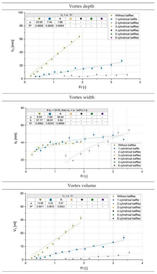
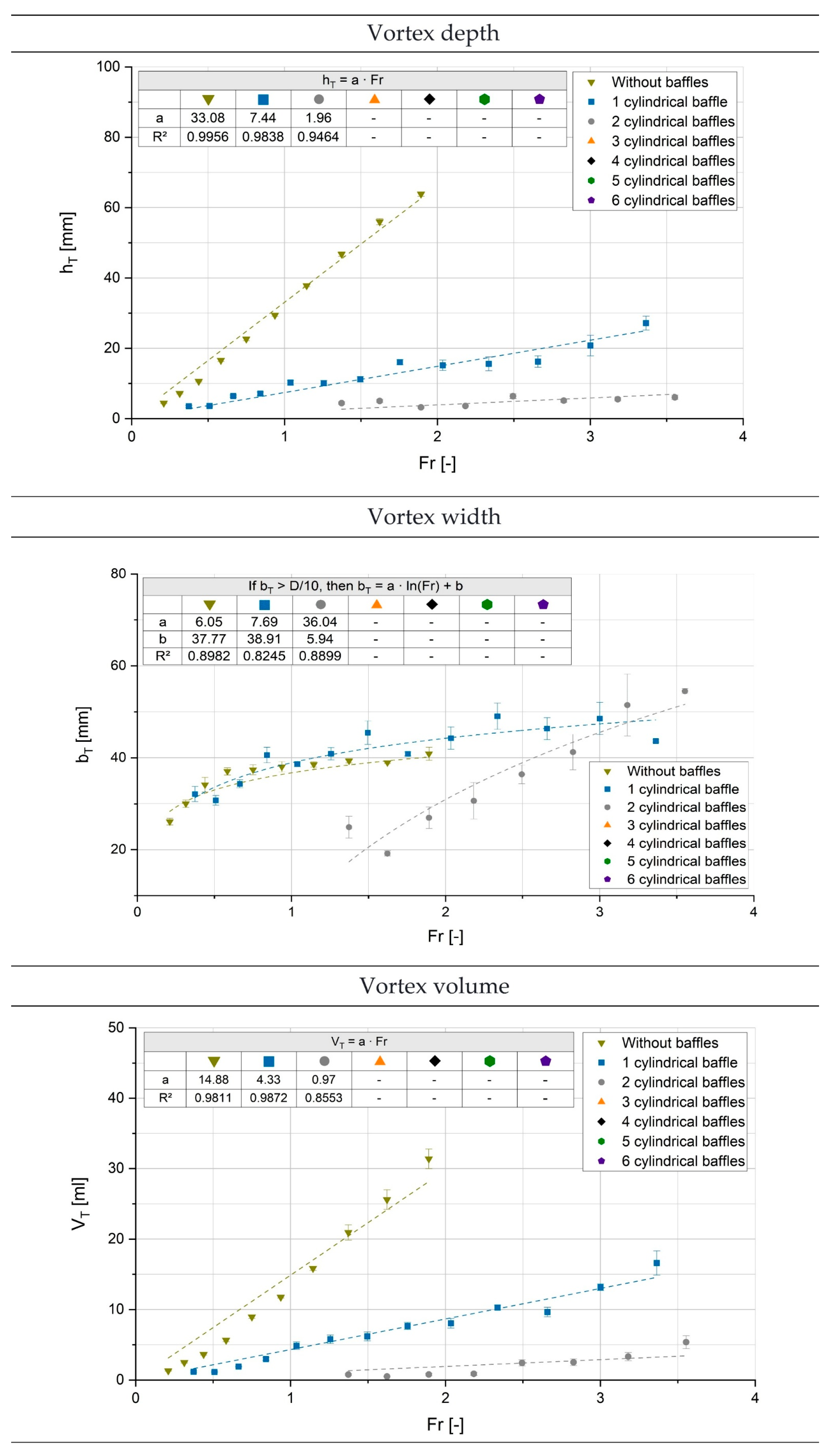
The vortex characteristics, depth, width and volume, are determined using the fourth-degree polynomial function as described in Section 2.2. These characteristics depend on the Froude number (see Equation (7)), as this number takes into account the processes occurring at the liquid surface [33].
Figure 7 shows examples of the depth, width and volume plotted against the Froude number with mathematical descriptions for the Propeller with one to six cylindrical baffles and without baffles. It can be seen that the Propeller no longer produces vortices when there are three or more cylindrical baffles installed.
Figure 7.
Results of mathematical description of vortex depth, width and volume from the investigation of a PR without and with one to six cylindrical baffles. The 3–6 baffles no longer produce vortices, so no data are given here.
The vortex depth can be represented very well with a linear function (R2 > 0.94) through the origin (0/0), a result that authors Zlokarnik [3] and Markopoulos et al. [12,14] were already able to determine for the relative vortex depth. The curve is placed through the origin because no vortex can exist at 0 rpm. The slope values show a significant decrease with an increase in baffle number, which clearly indicates a reduction in the size of the vortices. The slope value without baffles is reduced by more than a factor of four with just one baffle, and between one and two baffles, the value is minimized again by almost the same factor. This shows that the installation of baffles results in a significant reduction in vortex depth but in terms of power (cf. Section 3.1) it means higher power input.
A description of the vortex width can only be found in papers from the research group of Schultz [20,21,22,23,24,25], although the vortex width is particularly relevant for the installation of, for example, level measuring devices. The widths in the Propeller system can be described very well logarithmically (R2 > 0.82), but this can only be assumed if the vortices have a width above D/10. Moreover, without the use of baffles and with one baffle, the width tends towards a final value in the end of the results. This is because these vortices are central vortices and the evaluation method intersects the vortices at the original unstirred level line (cf. Figure 3) and the vortices above the level line are larger in width. In contrast, the vortex width with two baffles continues to increase, which is due to the fact that lateral vortices are present in this system. Overall, for the three vortex-producing stirring systems it can be concluded that the vortex width is between 20 mm and 60 mm, corresponding to approx. 18% and approx. 55% of the reactor inner diameter, respectively. Measuring devices in the reactor should therefore primarily be installed outside this bandwidth, i.e., closer to walls.
The vortex volume is also an important characteristic that has so far only been investigated by the research group of Schultz [20,21,22,23,24,25]. For the Propeller system, there is a linear correlation (R2 > 0.85), which allows the vortex volume to be predicted very accurately. As with the vortex depth, it can be seen that the volume decreases significantly with an increase in baffle number. Referring to a system without the use of baffles, a reduction of more than a factor of three is realized by only one baffle and more than a factor of four by two baffles.
Mathematical descriptions related to the ones in Figure 7 can also be found for the systems with other types and numbers of baffles, as well as for the Pitched-blade turbine system. However, these mathematical descriptions only apply to the reactor diameter of 110 mm and therefore a presentation of the remaining stirring systems does not generate any added value for the industry. Hence, dimensionless values are generated from the last measured and determined vortex data points representing the largest vortices, which can be transferred to industrial reactor sizes. These values enable the industry to design reactors more efficiently, thereby becoming more sustainable in the production of products.
In terms of scale-up considerations, the characteristics dimensionless vortex depth hTE, vortex width bTE and dimensionless vortex volume VTE are determined using Equations (8)–(10) below and can be calculated for different reactor sizes by rearranging them.
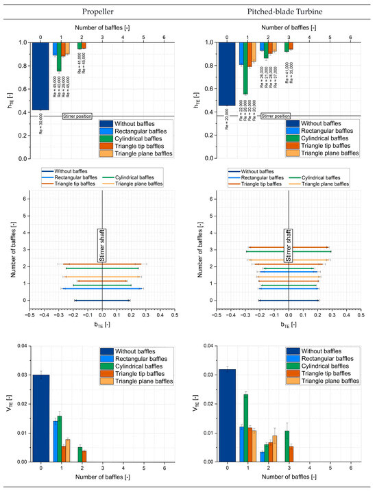
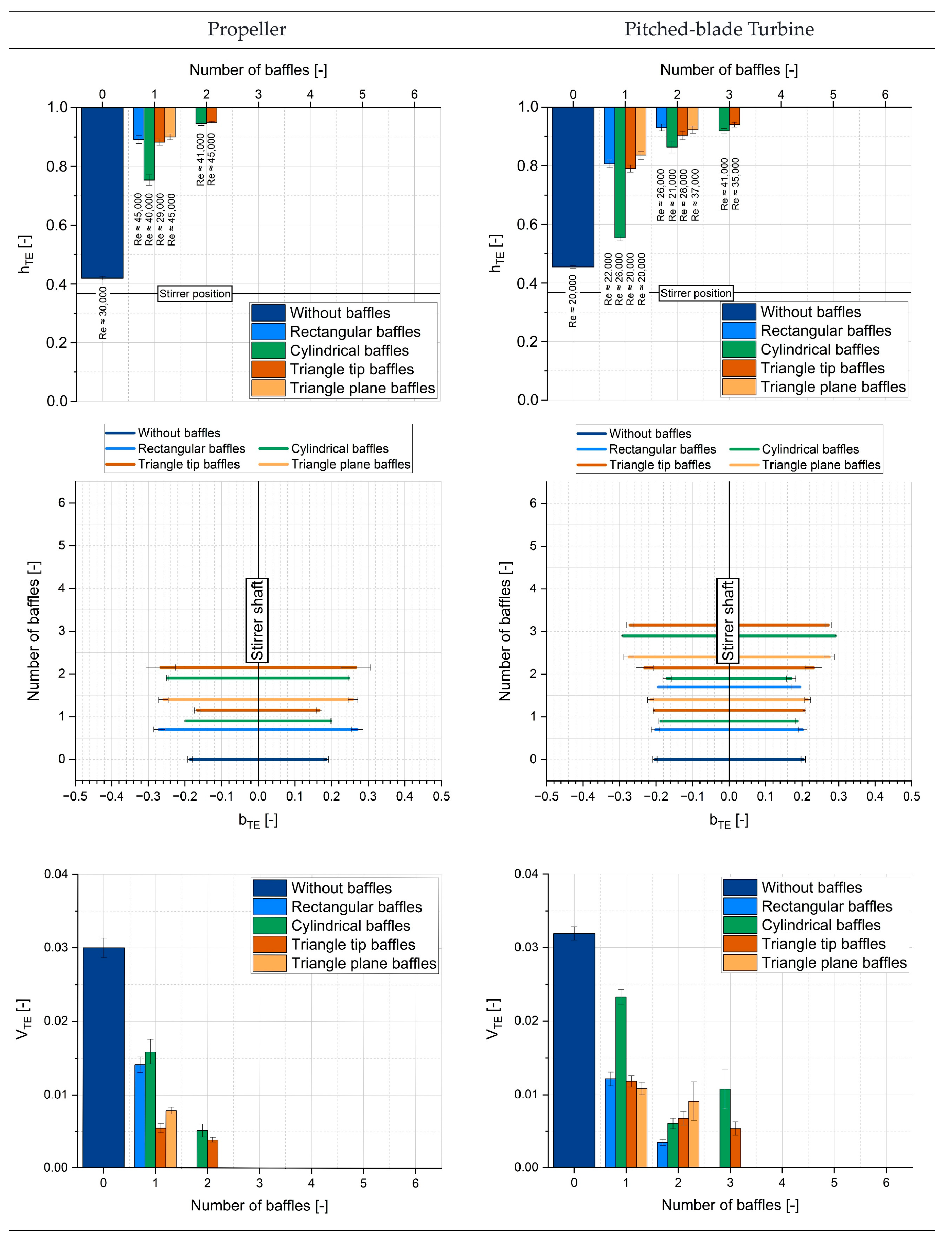
Figure 8 shows the dimensionless vortex characteristics against the number of baffles with the same color representing the same type of baffles. The Reynolds number at which these vortex characteristics occur can be found in the diagram along with the dimensionless vortex depth and the vortex type can be found in Table 4. When looking at the Reynolds numbers, it is noticeable that the Pitched-blade turbine system ceases much sooner than the Propeller system because air is introduced much sooner with the Pitched-blade turbine. This also corresponds to the power inputs found. Due to the higher power input, air bubbles can detach from the vortices much earlier and faster, which leads to the measurements being interrupted. In addition, it can be seen that, unlike with other types of baffles and with the Propeller, the Reynolds number for cylindrical baffles with the Pitched-blade turbine does not increase with two cylindrical baffles. This is due to the vortex shape changing from central to an unsteady lateral vortex (cf. Table 4), which occurs earlier with this baffle geometry and quickly produces a large amount of air entering the system. This is why the measurement had to be stopped at a lower Reynolds number.
Figure 8.
Dimensionless vortex depth, width and volume for PR and PBT for various baffles types and numbers.
Furthermore, it is clear that the Propeller system is already baffled with three baffles, regardless of the type of baffle, which is only possible with the Pitched-blade turbine with four baffles. For both stirrers, the rectangular and triangle plane baffles already show a fully baffled state with the number of baffles being one less than the numbers mentioned above.
The dimensionless vortex depth (see Figure 8, cf. Equation (8)) shows at first view how far the vortex extends from the stirrer position. A comparison of the two stirrers examined without the use of baffles shows that the vortex for the Propeller is slightly deeper than for the Pitched-blade turbine. For both stirrers, the error bars for data in these stirring systems are very small, because the central vortex moves little and constantly around the stirrer shaft. When used with baffles, the vortex depth of the Propeller system is significantly reduced by half or more. The depth is still very high with a cylindrical baffle, while with the other types of baffles the depth is very low and when two baffles are used, the vortex is completely eliminated or the vortex depth is very low.
For the Pitched-blade turbine system with baffles, the vortex depth cannot be reduced by half with a cylindrical baffle; as is the case with the Propeller system, it remains very deep with a cylindrical baffle. However, as with the Propeller system, it can be seen that the depth decreases further as the number of baffles increases and with three baffles the depth is very low or the vortex is completely eliminated with rectangular and triangular plane baffles.
The dimensionless vortex width (cf. Equation (9)) can be found in the middle of Figure 8 for both stirrers. It can be seen that the width of the vortices is subject to bigger fluctuations (see error bars) with baffles. This is because the baffles suppress the tangential component and avoid vortices, which means that the vortices are not constant and show more movement. Additionally, with a higher number of baffles, these vortices change from central to lateral ones. Without baffles, the error bars are very small, because these vortices are constantly centered, but this stirring system would have the widest vortices. Due to the evaluation method, the data appear to be different since the vortices rise from the width above the unstirred level line, so that the vortex without baffles is limited in width.
When comparing the stirrers in terms of vortex width, it can be seen that both stirrers yield values in the same size range. Overall, it can therefore be concluded that the vortices for Propeller and Pitched-blade turbine systems are on average at a maximum of approximately 1/3–3/5% of the reactor’s inner diameter.
The dimensionless vortex volume (cf. Equation (10)) can be seen in Figure 8 below. A comparison of the two stirrers without baffles shows that the Pitched-blade turbine system has a larger vortex volume and thus the width, which is slightly larger for the Pitched-blade turbine than for the Propeller system, appears to be decisive. Even with baffles, the Pitched-blade turbine has a larger vortex volume than the Propeller system. Furthermore, it is noticeable that the vortex volume is minimized as the number of baffles increases. Only with the Pitched-blade turbine is this not the case with three cylindrical baffles and with triangular plane baffles. This is due to the widths of the vortices found.
Overall, it appears that cylindrical baffles are the least effective at preventing vortices for the two axial stirrers examined, while rectangular baffles are the most effective in preventing vortices. This means that the flow around the baffles must be different and thus the disruptive effect must also be different. This will be investigated in following studies using Particle Image Velocimetry (PIV).
Table 4 below shows the types of vortices found with the different types and number of baffles compared with the theoretical calculations (cf. Table 3). The table also shows an initial optimization of Equation (2) and a comparison with the theory. A “−“ sign represents a central vortex, “o“ a lateral vortex and a “+“ sign a surface turbulence. If the theoretical predictions from Table 3 match with the vortices found in Table 4, it is indicated with a green hook ✓, and if they do not match, with a red cross ⨯. The predictions for the state without baffles are not listed, because BW = 0 and BWvb is bigger, meaning that the prediction of a vortex corresponds with the measurements.
Table 4.
Real conditions of the stirring configurations examined (−, central vortex; o, unsteady lateral vortex; +, surface turbulence) with the agreement with theoretical predictions of the baffle state (✓ theory and practice agree, ⨯ theory and practice do not agree) and the agreement with theoretical predictions of the baffle state with adjusted values for Equation (2) (PR: 0.33; PBT: 0.29).
It is clear in Table 4, in the entry “Baffle geometries—Liepe et al. [6] Equations (1) and (2)“, that 6 cases out of 48 measurements with baffles are not correctly predicted, which means an incorrect prediction rate of 12.5%. These predictions are therefore not useless. In fact, with 87.5% correct predictions, at least for the investigated axial, single-stage stirrers, they are surprisingly accurate, considering the age of the proposed equations and the limited measurement methods available at the time, although it could be optimized by today’s standards. Since there is currently no other way to predict vortices than with the dimensionless baffle index or with time-consuming experiments, the calculation method for axial stirring systems does not seem to be bad.
Looking at each type of baffles, the false prediction rate is ~8% for rectangular baffles, ~25% for cylindrical baffles, ~17% for triangular tip baffles and 0% for triangular plane baffles. For both stirrers, the cylindrical baffle thus has the highest false-prediction rate, while the predictions for the triangular plane baffles are completely correct. It is also noticeable that the prediction for the Propeller system with rectangular baffles is correct. For this reason, less incorrect predictions (approximately 8%) are shown with the Propeller than with the Pitched-blade turbine system, which yields twice as many incorrect predictions as with the Propeller.
If the baffle index is examined more closely and a dimensional analysis is performed, it becomes apparent that Equations (1) and (2) were originally determined from geometric parameters. In Equation (1), the shape factor of the baffles, the number of the baffles and the wake effects (0.8) of the baffles were added. How the authors considered the shape factors and wake effects specifically is not described in the literature. The same applies to the factor of 0.36 in Equation (2). Neither the origin or the function of this factor is transparent.
According to Table 4, every eighth prediction is wrong, which is still a relatively high rate of false predictions. Hence, at first view it might be reasonable to modify the factor 0.36 in Equation (2). If a value of 0.33 is assumed for the Propeller system, half of the false predictions are turned into correct ones (see Table 4 “Baffle geometries-adjusted Equation (2)”). An improvement with the Pitched-blade turbine system is obtained with the value 0.29, which also corrects half of the false statements. The thereby adjusted values halve the false predictions very effectively and in a simple way. However, it is also obvious that it is not possible by such a rudimentary optimization cycle to generate a completely correct prediction; there was only improvement for the predictions with cylindrical baffles. This means that it is also very likely that the wake effects and shape factors of the baffles will need to be adjusted. To this end, a subsequent study will examine the exact flow behavior around the baffles using Particle Image Velocimetry (PIV). It is expected that this will allow a comprehensive adaptation/optimization of these parameters to be carried out.
Nevertheless, the initial adaptation appears to be a first step toward the long-term goal of optimizing the baffle index in order to make industrial reactors more economical and sustainable. In this context, it should not be forgotten that axial stirrers are in principle less susceptible to vortex formation and therefore optimization studies must subsequently be carried out for radial stirrers and multi-stage systems in order to make a holistically improved prediction for a wide variety of stirring elements and thus provide users with improved design options and recommendations.
4. Conclusions
In summary, this study presents, for the first time, comprehensive results on the power input and vortex characteristics (depth, width and volume) of the industrially important axial stirring systems, Propeller and Pitched-blade turbine, with different baffle geometries and numbers, as well as without baffles. In addition, to our knowledge it provides the first definition of when a deformation of the liquid/gas interface can be called a vortex in stirred systems and which different types of vortices can occur. Furthermore, the geometric properties of vortices are made accessible with dimensionless values for scale-up considerations in industry.
In terms of power input, as expected it was found that the Pitched-blade turbine requires more power than a Propeller and that the power characteristic curves tend to higher values with an increasing number of baffles. For both stirrers, differences in power characteristics were observed depending on the geometry of the baffles. The Propeller with triangular plane baffles has the highest power input and the triangular tip baffle consumes the least, while the Pitched-blade turbine with rectangular baffles requires the most power and the cylindrical baffle requires the least. A comparison of the determined Ne values with the literature can only be made to a limited extent, as there is often a lack of transparency regarding stirrer and reactor design as well as measurement methods in the literature so far.
The results of the vortices display that the installation of baffles significantly minimizes the vortex characteristics as their number increases. For both axial stirrers, the statement from the literature that the systems are sufficiently baffled with four baffles [1,2,6] is accurate. For the Propeller, a fully baffled system was already observed with two rectangular and triangular plane baffles, as well as with three cylindrical or triangular tip baffles. The same findings were obtained for the Pitched-blade turbine but with a higher number in each case. Furthermore, the cylindrical baffles produced the highest vortex depth, width and volumes for both stirrers after those systems without baffles, which suggests that they allow a better tangential flow around and thus the baffles do not specifically prevent the tangential component, as is the case with rectangular baffles, for example. Cylindrical baffle geometries are therefore only recommended to a limited extent and are significantly less efficient than the other geometries tested.
The predictions of vortices using the baffle index number have shown that, although the outdated index still provides relatively good predictions, optimization is needed because not all predictions are correct and it is expected that the false forecasts will be significantly more critical for radial agitators. Furthermore, no prediction is currently possible at all for multi-stage stirring systems. Initial and simple adjustment attempts in this study have already been successful and minimizes false predictions by half (to ~6%), but 3 out of 48 predictions are still incorrect. For this reason, a follow-up study will comprehensively optimize considering the wake effects and shape factors and ultimately adapt also the constant factor in formula (current value 0.36).
Overall, a comprehensive analysis of axial stirring systems was successfully carried out and practical results were provided for the production and process industry in order to enable the design of reactors more sustainable and economical.
Author Contributions
Conceptualization, L.L., M.U. and H.J.S.; methodology, L.L. and H.J.S.; software, L.L.; validation, L.L., M.U. and H.J.S.; formal analysis, L.L., M.U. and H.J.S.; investigation, L.L. and H.J.S.; resources, H.J.S.; data curation, L.L.; writing—original draft preparation, L.L. and H.J.S.; writing—review and editing, L.L., M.U. and H.J.S.; visualization, L.L.; supervision, M.U. and H.J.S.; project administration, M.U. and H.J.S.; funding acquisition, H.J.S. All authors have read and agreed to the published version of the manuscript.
Funding
This research received no external funding.
Institutional Review Board Statement
Not applicable.
Informed Consent Statement
Not applicable.
Data Availability Statement
The data presented in this study are available on request from the corresponding author.
Acknowledgments
The authors acknowledge support for the publication costs by the Open Access Publication Fund of Hochschule Niederrhein as well as the Institute for Coatings and Surface Chemistry (ILOC).
Conflicts of Interest
The authors declare no conflicts of interest.
Abbreviations
The following abbreviations are used in this manuscript:
| a1–a4 | [-] | Coefficient of the polynomial function fourth-degree |
| aS | [mm; m] | Wall distance of the baffles |
| a | [mm; m; ml; m3] | Slope factor of the linear functions and logarithmic function |
| b | [mm; m] | Intercept of the logarithmic function |
| bS | [mm; m] | Width of the baffles |
| bT | [mm; m] | Vortex width |
| bTE | [-] | Dimensionless vortex width of the last evaluated vortex result |
| [mm; m] | Beginning of the vortex width (left side) | |
| [mm; m] | End of the vortex width (right side) | |
| BW | [-] | Dimensionless baffle index (German: dimensionslose Bewehrungskennzahl) |
| BWvb | [-] | Dimensionless fully baffled index (German: dimensionslose Bewehrungskennzahl der Vollbewehrung) |
| CFD | Computational Fluid Dynamics | |
| cF | [-] | Baffle geometry coefficient |
| dR | [mm; m] | Stirrer diameter |
| D | [mm; m] | Reactor inner diameter |
| Fr | [-] | Froude number |
| G | s−2] | Gravitational acceleration |
| hT′ | [mm; m] | First derivative of the polynomial function |
| [mm; m] | Polynomial function | |
| hT | [mm; m] | Vortex depth |
| hTE | [-] | Dimensionless vortex depth of the last evaluated vortex result |
| hR | [mm; m] | Bottom distance from the stirrer to the reactor bottom |
| hS | [mm; m] | Bottom distance from the baffles to the reactor bottom |
| H | [mm; m] | Liquid filling height |
| HS,eff | [mm; m] | Immersion depth of the baffles |
| LED | Light-emitting diode | |
| M | s−2] | Torque value |
| N | [-] | Number of baffles |
| Ne | [-] | Newton number |
| n | [rpm; s−1] | Rotational frequency |
| P | s−3] | Power |
| PBT | Pitched-blade turbine | |
| PIV | Particle Image Velocimetry | |
| PMMA | Polymethylmethacrylate | |
| PLA | Polylactic acid | |
| PR | Propeller | |
| ReR | [-] | Stirrer Reynolds number |
| R2 | [-] | Coefficient of determination |
| TPU | Thermoplastic Polyurethane | |
| V | [ml; m3] | Reactor volume |
| VT | [ml; m3] | Volume of the vortex |
| VTE | [-] | Dimensionless vortex volume of the last evaluated vortex result |
| w | [mm; m] | Wall thickness of reactor |
| s−2] | Kinematic Viscosity | |
| m−3] | Density |
References
- Zlokarnik, M. Rührtechnik; Springer: Berlin/Heidelberg, Germany, 1999; ISBN 3-540-64639-6. [Google Scholar]
- Kraume, M. Mischen und Rühren: Grundlagen und Moderne Verfahren; Wiley-VCH: Weinheim, Germany, 2007; ISBN 978-3-527-30709-8. [Google Scholar]
- Zlokarnik, M. Trombentiefe beim Rühren in unbewehrten Behältern. Chem. Ing. Tech. 1971, 43, 1028–1030. [Google Scholar] [CrossRef] [Scilit]
- Komarov, S.V.; Yamamoto, T.; Arai, H. Incorporation of Powder Particles into an Impeller-Stirred Liquid Bath through Vortex Formation. Materials 2021, 14, 2710. [Google Scholar] [CrossRef] [Scilit]
- Urban, K.; Wagner, G.; Schaffner, D.; Ulrich, J. Visualization of Vortices in Emulsification Processes. Chem. Eng. Res. Des. 2006, 84, 1081–1085. [Google Scholar] [CrossRef] [Scilit]
- Liepe, F.; Sperling, R.; Jembere, S. Rührwerke: Theoretische Grundlagen, Auslegung und Bewertung, 1st ed.; Eigenverl: Berlin, Germany, 1998; ISBN 3-00-003195-2. [Google Scholar]
- Płusa, T.; Talaga, J.; Duda, A.; Duda, P. Modeling mixing dynamics in uncovered baffled and unbaffled stirred tanks. AIChE J. 2021, 67, e17322. [Google Scholar] [CrossRef] [Scilit]
- Fan, Y.; Sun, J.; Jin, J.; Sun, K.; Zhang, H.; Chen, W.; Li, Y. Effects of baffle on flow structure and cyclic variation in stirred tanks with Rushton turbine. AIP Adv. 2022, 12, 015202. [Google Scholar] [CrossRef] [Scilit]
- Fan, Y.; Sun, J.; Jin, J.; Zhang, H.; Chen, W. The effect of baffle on flow structures and dynamics stirred by pitch blade turbine. Chem. Eng. Res. Des. 2021, 168, 227–238. [Google Scholar] [CrossRef] [Scilit]
- Glover, G.C.M.; Fitzpatrick, J.J. Modelling vortex formation in an unbaffled stirred tank reactors. Chem. Eng. J. 2007, 127, 11–22. [Google Scholar] [CrossRef] [Scilit]
- Rajavathsavai, D.; Khapre, A.; Munshi, B. Numerical Study of Vortex Formation Inside A Stirred Tank. Int. J. Chem. Mol. Eng. 2015, 8, 1437–1442. [Google Scholar] [CrossRef]
- Markopoulos, J.; Kontogeorgaki, E. Vortex depth in unbaffled single and multiple impeller agitated vessels. Chem. Eng. Technol. 1995, 18, 68–74. [Google Scholar] [CrossRef] [Scilit]
- Rieger, F.; Ditl, P.; Novák, V. Vortex depth in mixed unbaffled vessels. Chem. Eng. Sci. 1979, 34, 397–403. [Google Scholar] [CrossRef] [Scilit]
- Markopoulos, J.; Kontogeorgaki, E. Trombenbildung in unbewehrten Rührbehältern mit ein- und zweistufiger Rühreranordnung. Chem. Ing. Tech. 1993, 65, 839–841. [Google Scholar] [CrossRef] [Scilit]
- Busciglio, A.; Grisafi, F.; Scargiali, F.; Davi, M.L.; Brucato, A. Vortex shape in unbaffled stirred vessels: Experimental study via digital image analysis. Chem. Eng. Trans. 2011, 24, 1387–1392. [Google Scholar] [CrossRef] [Scilit]
- Scargiali, F.; Busciglio, A.; Grisafi, F.; Tamburini, A.; Micale, G.; Brucato, A. Power Consumption in Uncovered Unbaffled Stirred Tanks: Influence of the Viscosity and Flow Regime. Ind. Eng. Chem. Res. 2013, 52, 14998–15005. [Google Scholar] [CrossRef] [Scilit]
- Prakash, B.; Bhatelia, T.; Wadnerkar, D.; Shah, M.T.; Pareek, V.K.; Utikar, R.P. Vortex shape and gas-liquid hydrodynamics in unbaffled stirred tank. Can. J. Chem. Eng. 2019, 97, 1913–1920. [Google Scholar] [CrossRef] [Scilit]
- Deshpande, S.S.; Kar, K.K.; Walker, J.; Pressler, J.; Su, W. An experimental and computational investigation of vortex formation in an unbaffled stirred tank. Chem. Eng. Sci. 2017, 168, 495–506. [Google Scholar] [CrossRef] [Scilit]
- Li, L.; Xu, B. Numerical simulation of hydrodynamics in an uncovered unbaffled stirred tank. Chem. Pap. 2017, 71, 1863–1875. [Google Scholar] [CrossRef] [Scilit]
- Lenters, L.; Matzke, M.; Ranft, E.; Schultz, H.J. Dependencies of the vortex formation in multistage stirring systems. Chem. Ing. Tech. 2022, 94, 1359. [Google Scholar] [CrossRef] [Scilit]
- Lenters, L.; Ulbricht, M.; Schultz, H.J. Influence of baffle number and type on the vortex formation in various one- and two-stage stirring systems. In Proceedings of the Jahrestreffen DECHEMA/VDI-Fachgruppen Mischvorgänge, Hochdruckverfahrenstechnik und Mehrphasenströmungen, Hamburg, Germany, 19–21 March 2025. [Google Scholar]
- Lenters, L.; Asvand, A.; Braun, V.; Ulbricht, M.; Schultz, H.J. Vortex Formation of Combined Two-Stage Stirring Systems. In Proceedings of the Jahrestreffen DECHEMA/VDI-Fachgruppen Mischvorgänge, Hochdruckverfahrenstechnik und Mehrphasenströmungen, Hamburg, Germany, 19–21 March 2025. [Google Scholar] [CrossRef]
- Lenters, L.; Greeff, K.d.; Dominkovic, L.; Ulbricht, M.; Schultz, H.J. Trombenuntersuchungen eines 6-Blattscheibenrührers in Medien unterschiedlicher Viskosität. In Proceedings of the Jahrestreffen der Dechema/VDI-Fachgruppe Mischvorgänge, Schopfheim, Germany, 6–7 March 2024. [Google Scholar] [CrossRef]
- Lenters, L.; Ulbricht, M.; Schultz, H.J. Algorithm for detecting the formation of vortices in single- and multi-stage stirring systems. In Proceedings of the 14th European Congress of Chemical Engineering and 7th European Congress of Applied Biotechnology, Berlin, Germany, 17–21 September 2023. [Google Scholar] [CrossRef]
- Lenters, L.; Ulbricht, M.; Schultz, H.J. Impact of baffle geometry and baffle number on vortex formation in single-stage radial stirring systems. Int. J. Chem. Eng. 2026, 269, 7811583. [Google Scholar]
- Kögel, L.; Gieseking, A.; Zierberg, C.; Ulbricht, M.; Schultz, H.J. Intensification of Mixing Processes in Stirred Tanks Using Specific-Power-Matching Double-Stage Configurations of Radially and Axially Pumping Impellers. ChemEngineering 2026, 10, 17. [Google Scholar] [CrossRef] [Scilit]
- Karcz, J.; Major, M. An Effect of a Baffle Length on the Power Consumption in an Agitated Vessel. Chem. Eng. Process. Process Intensif. 1998, 37, 249–256. [Google Scholar] [CrossRef] [Scilit]
- Heyter, A.; Wollny, S. Influence of Different Baffle Variations on the Effectiveness of Multi-Stage Agitated Vessels. Chem. Ing. Tech. 2017, 89, 416–423. [Google Scholar] [CrossRef] [Scilit]
- Deutsches Institut für Normung. DIN 28131: Rührer und Stromstörer für Rührbehälter; Beuth-Verlag: Berlin, Germany, 1992. [Google Scholar]
- EKATO. The Book, 3rd ed.; EKATO: Schopfheim, Germany, 2012; ISBN 978-3-00-037510-1. [Google Scholar]
- Matzke, M.; Behrens, C.; Jongebloed, N.; Steins, D.; Ulbricht, M.; Schultz, H.J. Investigation and Visualization of Flow Fields in Stirred Tank Reactors Using a Fluorescence Tracer Method. Chem. Ing. Tech. 2022, 94, 1131–1140. [Google Scholar] [CrossRef] [Scilit]
- Wollny, S.; Sperling, R. Rührtechnologische Forschung zum Suspendieren und Dispergieren. Chem. Ing. Tech. 2021, 93, 117–128. [Google Scholar] [CrossRef] [Scilit]
- VDI-Gesellschaft Verfahrenstechnik und Chemieingenieurwesen. VDI-Wärmeatlas; Springer: Berlin/Heidelberg, Germany, 2013; ISBN 978-3-642-19980-6. [Google Scholar]
- Liepe, F. Verfahrenstechnische Berechnungsmethoden, Teil 4 Stoffvereinigen in Fluiden Phasen; VCH Verlagsgesellschaft: Weinheim, Germany, 1988; ISBN 3-527-26205-9. [Google Scholar]
- Ma, Z. Impeller Power Draw Across The Full Reynolds Number Spectrum. Master’s Thesis, University of Dayton, Dayton, OH, USA, 2014. [Google Scholar]
- Wu, J.; Zhu, Y.; Pullum, L. Impeller Geometry Effect on Velocity and Solids Suspension. Chem. Eng. Res. Des. 2001, 79, 989–997. [Google Scholar] [CrossRef] [Scilit]
- Christen, D.S. Praxiswissen der chemischen Verfahrenstechnik; Springer: Berlin/Heidelberg, Germany, 2010; ISBN 978-3-540-88974-8. [Google Scholar]
- Bliem, V. Untersuchung des Einflusses der Strömungsverhältnisse auf den Wärmeübergang in Rührreaktoren mit Rohrschlangeneinbauten Mittels Particle Image Velocimetry und Laser Induced Fluorescence. Doctoral Dissertation, Universität Duisburg-Essen, Essen, Germany, 2016. [Google Scholar]

Disclaimer/Publisher’s Note: The statements, opinions and data contained in all publications are solely those of the individual author(s) and contributor(s) and not of MDPI and/or the editor(s). MDPI and/or the editor(s) disclaim responsibility for any injury to people or property resulting from any ideas, methods, instructions or products referred to in the content. |
© 2026 by the authors. Licensee MDPI, Basel, Switzerland. This article is an open access article distributed under the terms and conditions of the Creative Commons Attribution (CC BY) license.