


Abstract
With the global energy transition and large-scale renewable integration, thermal power units are shifting from base-load to peak-shaving roles, but deep peak shaving may cause combustion instability and increased emissions. High-temperature solid-particle thermal storage offers a low-cost and wide-temperature-range solution for enhancing unit flexibility. This study proposes a flue-gas-driven solid-particle thermal storage system in which high-temperature flue gas extracted from the furnace directly heats solid particles through a multi-stage suspension preheating process. An industrial-scale suspension preheater was modeled using the Computational Particle Fluid Dynamics (CPFD) method to investigate gas–solid flow and heat transfer for quartz sand with different particle sizes and cement raw meal. The effects of particle size and thermophysical properties on particle motion, temperature evolution, gas–solid heat transfer coefficient, and flow-field characteristics were systematically analyzed. The results show that the outlet flue-gas temperature was approximately 705–725 K under the investigated conditions. For quartz sand, the particle outlet temperature decreased from approximately 715 K to 660 K as the particle size increased from 0.45–0.55 mm to 1.45–1.55 mm. The gas–solid heat transfer coefficient of quartz sand remained relatively stable, mainly ranging from approximately 450 to 900 W/(m2·K), whereas that of fine raw meal was approximately 1750–2600 W/(m2·K). Larger quartz sand particles also exhibited more pronounced wall attachment because of their higher inertia. These results demonstrate the potential applicability of suspension-preheater-based direct flue-gas heating for high-temperature solid-particle thermal energy storage and provide quantitative information for the design and operation of such systems.
1. Introduction
Driven by China’s “dual carbon” goals, the integration of a high proportion of renewable energy into the grid has created an unprecedentedly urgent demand for large-scale, low-cost energy storage in the power system [1,2,3]. China has elevated this to a national strategic priority. The 15th Five-Year Plan explicitly proposes vigorously developing new-type energy storage, with plans to reach an installed capacity of over 180 million kilowatts by 2027, driving approximately 250 billion yuan in direct investment, and projections that installed capacity could reach 300 million kilowatts by the end of the 15th Five-Year Plan period.
Against this background, thermal power units responsible for base-load and peak-shaving tasks urgently need to achieve deep flexible regulation by coupling with energy storage [4]. Using the high-temperature flue gas generated by the thermal power plant itself to directly heat thermal storage particles can form a deep “generation–storage” coupling, providing a highly promising technical pathway for the synergistic operation of thermal power and energy storage [5,6].
Currently, the relatively mature molten salt thermal storage technology still faces challenges such as corrosion, solidification, and limited high-temperature stability [7]. Meanwhile, considerable research has been devoted to developing advanced thermal energy storage materials and improving their thermal storage and stability characteristics [8]. In contrast, solid-particle thermal storage employs inexpensive, non-corrosive, and high-temperature-resistant materials, such as quartz sand and alumina particles. Compared with molten salts, these materials offer substantially lower storage-medium costs while providing high thermal energy storage capacity and excellent thermal and chemical stability [9,10]. However, the heating strategy adopted for the storage particles plays a critical role in determining the overall system efficiency and operational lifetime In existing studies, the mainstream electric heating approach suffers from uneven temperature distribution and excessively high local heat flux when scaled up, which may cause particle sintering and agglomeration [11,12]. Although direct heating of storage particles with high-temperature flue gas can overcome some of these limitations, conventional fixed-bed configurations are susceptible to non-uniform temperature distributions due to limited particle movement, whereas fluidized-bed systems introduce additional engineering challenges associated with high-temperature gas distribution and particle fluidization [13,14]. Therefore, developing a heating method that enables efficient and uniform heat exchange between particles and high-temperature flue gas has become the key to the industrial application of solid-particle thermal storage.
The well-established multi-stage suspension preheating technology in the cement industry provides a promising technical route for addressing this challenge, owing to its efficient gas–solid heat transfer and staged heat recovery characteristics [15,16]. By suspending particles in a gas stream to form a dilute-phase or dense-phase flow regime, this technology promotes direct gas–solid contact and rapid convective heat transfer, enabling efficient and relatively uniform particle heating. The long-standing industrial application of suspension preheaters also demonstrates their suitability for operation under high-temperature and dust-laden conditions [17,18]. By integrating this principle into high-temperature solid-particle thermal energy storage systems, boiler flue gas can be directly utilized as a heat source for multi-stage suspension heating of millimeter-scale storage particles, thereby providing a potential route to improve heating uniformity, particle durability, and overall system economics [19,20]. However, existing numerical studies on suspension preheaters in the literature have mainly focused on gas–solid flow characteristics and heat transfer within individual cyclone separators, with the solid phase generally consisting of micron-sized cement raw meal. In contrast, systematic investigations of gas–solid flow and heat transfer involving millimeter-sized particles in suspension preheaters for high-temperature thermal storage applications remain limited. In particular, quantitative data concerning particle–flue gas heat transfer in the riser duct are still scarce [21,22].
To address this research gap, this study employs the Barracuda Virtual Reactor 24.0.0 (CPFD Software, LLC, Houston, TX, USA) software based on the Computational Particle Fluid Dynamics (CPFD) method to numerically investigate the multi-stage suspension heating of solid particles by high-temperature flue gas [23,24]. The CPFD method represents a large number of physical particles with a relatively small number of “computational particles” sharing similar physical properties, while the gas phase is solved on an Eulerian grid. Momentum and energy exchange between the gas and particle phases is achieved through interphase coupling, including drag and convective heat transfer. By avoiding the need to explicitly resolve individual particle–particle contacts, CPFD can efficiently simulate large-scale dense gas–solid flows with reasonable computational requirements, making it more computationally tractable than fully resolved DEM simulations for industrial-scale systems [25,26]. It is therefore a reasonable choice for system-level simulation of multi-stage suspension heat exchange. The novelty of this work lies in applying the Barracuda platform to the simulation of suspension heating for solid-particle thermal storage, and systematically comparing the thermal storage case (millimeter-sized quartz sand particles) with the raw meal case. Under differences in material properties and operating conditions, it reveals the particle inlet and outlet temperatures, gas–solid heat transfer coefficients, and flow-field evolution patterns under different operating conditions. The research results will provide key theoretical support for the engineering design of flue gas heaters in high-temperature solid-particle thermal storage systems and provide data support for the development of high-temperature solid-particle energy storage technology in China.
The novelty of this study can be summarized in three aspects. First, a flue-gas-driven solid-particle thermal energy storage system is proposed and numerically investigated, extending the application of CPFD-based suspension preheater simulations from conventional fine cement raw meal to millimeter-scale solid particles for thermal energy storage. Second, under the same gas-flow and solid-feed conditions, quartz sand particles with different millimeter-scale particle sizes are systematically compared with cement raw meal, thereby allowing the effects of particle size and thermophysical properties on gas–solid transport and heat transfer to be distinguished. Third, the axial evolution of particle temperature, flue-gas temperature, particle slip velocity, and gas–solid heat transfer coefficient in the riser duct and cyclone separator is quantitatively analyzed, providing a numerical basis for the design of flue-gas-driven solid-particle thermal energy storage systems.
2. Mathematical Model
2.1. Governing Equations
In this study, the Computational Particle Fluid Dynamics (CPFD) method was employed to investigate particle inlet and outlet temperatures, gas–solid heat transfer coefficients, and flow-field evolution under different operating conditions [27,28]. The CPFD approach adopts an Eulerian–Lagrangian framework for describing gas–solid multiphase flows, in which the gas phase is solved on an Eulerian grid while the particle phase is tracked using Lagrangian computational particle [29,30]. The gas-phase turbulence was modeled using the Large Eddy Simulation (LES) approach with the Smagorinsky subgrid-scale model. The Smagorinsky constant was set to 0.01, consistent with the default value commonly used in CPFD-Barracuda simulations. Under the present operating conditions, the characteristic gas-phase Reynolds number based on the riser diameter is approximately 8.4 × 10⁵, These values indicate a highly turbulent gas flow. The governing equations and model formulations used in the simulations are summarized in Table 1.
Table 1.
Governing equations for gas and particle phases.
2.2. Drag Models
Because the particle size and flow characteristics differ substantially between quartz sand and raw meal, different gas–solid drag models were employed for the two particle systems. For the relatively coarse quartz sand particles (0.45–1.5 mm), the Wen–Yu–Ergun combined drag model was adopted to account for gas–solid momentum exchange under both dilute and relatively dense flow conditions [35,36]. For the fine raw meal particles (0.037–0.045 mm), the EMMS–Yang drag model was employed. The EMMS approach considers the multiscale and heterogeneous structures inherent in gas–solid flows and incorporates the effects of particle clustering on interphase drag [37]. Previous MP-PIC simulations have also demonstrated that the selection of drag correlations should account for particle properties and flow regimes, with heterogeneous drag models providing improved descriptions for gas–solid systems characterized by significant mesoscale structures [38]. Therefore, the EMMS–Yang drag model was selected for the raw meal system in the present study, where the fine particles are prone to aggregation and the gas–solid flow exhibits pronounced heterogeneous structures. The specific gas–solid drag models employed for the two particle systems are summarized in Table 2.
Table 2.
Drag models and correlations for gas–solid momentum exchange.
2.3. Heat Transfer Model
The thermal behavior of the gas–solid system was investigated using the Computational Particle Fluid Dynamics (CPFD) approach implemented in Barracuda Virtual Reactor 24.0.0. In this study, heat exchange was considered only between the gas and particle phases, including gas–particle convection and thermal radiation described by the P-1 model. The heat transfer rate between the two phases was characterized by the fluid–particle heat transfer coefficient. As a simplified form of the general P-N mode, the P-1 radiation model accounts for radiative heat transfer between particles and the surrounding fluid [40]. The specific heat transfer model structures adopted in this study are summarized as shown in the following Table 3.
Table 3.
Heat transfer models: fluid–particle convection and P-1 radiation model.
3. Model Setup and Validation
3.1. Geometric Model
In the cement industry, raw meal preheating is typically achieved using multi-stage series-connected suspension preheaters. Since the various stages of the preheater exhibit certain similarities in structural form and in gas–solid two-phase flow and heat transfer mechanisms, this study selects one stage of a suspension preheater from an actual industrial production line as the research object in order to reduce numerical computational cost and improve computational efficiency. A three-dimensional numerical simulation of the gas–solid two-phase flow and heat transfer process inside this stage is carried out.
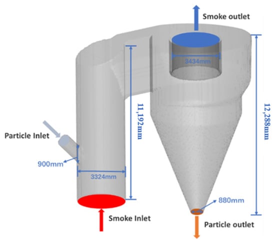
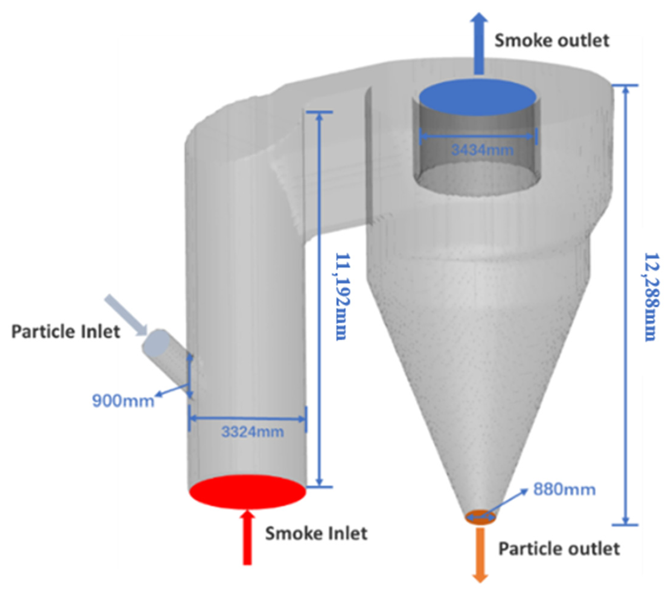
In this paper, a three-dimensional physical model is established based on the first-stage suspension preheater of a 2000 t/d cement production line in Zambia, as shown in Figure 1. The system mainly consists of a riser duct, a cyclone separator, and inlet and outlet ports for the gas phase and particle phase. The total height of the riser duct is 11.192 m, and its diameter is 3.324 m. The cyclone separator has a cylinder diameter of 7.482 m, a central pipe diameter of 3.434 m, and an overall height of 12.288 m. The feed inlet diameter is 0.90 m, and the discharge outlet diameter is 0.88 m.
Figure 1.
Geometry and dimensions of the suspension preheater.
In the numerical simulation, the particle phase is introduced through an injection boundary condition. Particles are injected into the feed pipe through virtual injection points and then enter the riser duct with the gas flow. The high-temperature flue gas and the feed-carrying air enter the computational domain from the bottom of the riser duct and the top of the feed pipe, respectively. The wall boundary conditions of the model are set as adiabatic. The outlet at the top of the cyclone separator is defined as a pressure outlet, with the outlet pressure set to 101,000 Pa.
3.2. Parameter Settings
Gas–Solid Characteristics
In this paper, raw meal particles commonly used in actual cement preheating systems and quartz sand with three different particle sizes are selected as the heated media. Among them, the raw meal particles are mainly composed of calcium-bearing minerals such as CaCO3 and have a relatively small particle size, while the quartz sand is mainly composed of SiO2 and has a larger particle size than the raw meal particles. The specific material properties are shown in Table 4.
Table 4.
Material parameters.
The gas-phase medium in the system was based on the actual operating conditions and consisted primarily of CO2, O2, N2, SO2, and H2O. The volume fractions of the individual gas components, together with the thermophysical properties of the flue-gas mixture, including specific heat capacity, dynamic viscosity, and thermal conductivity, are summarized in Table 5. These properties were used to characterize the thermal and flow behavior of the gas phase in the CPFD simulations.
Table 5.
Flue-gas composition and thermophysical properties at 773 K.
At the initial moment of the simulation, the system is filled with air, the initial velocities of both the fluid and particles are set to 0 m/s, and the initial temperature inside the system is set to a uniform constant value of 300 K. After the calculation starts, high-temperature flue gas and particles enter the computational domain from their respective inlets. As the calculation time progresses, the system gradually transitions from the initial air state to the actual gas–solid two-phase flow state in which flue gas and particles coexist. The above initialization method can avoid excessive interference of the initial conditions on particle flow, and is conducive to analyzing the evolution laws of particle flow and heat transfer during the system startup process.
In this paper, for quartz sand particles and raw meal particles with different diameters, the same flue gas inlet flow rate and the same material feed rate are selected, and the heat transfer and flow characteristics are compared under four different working conditions according to the specific particle size ranges and particle types, as shown in Table 6.
Table 6.
Operating conditions.
3.3. Boundary Conditions and Simulation Parameter Settings
This paper focuses on the flow and heat transfer characteristics of particles with different physical properties and different particle sizes in a suspension preheater. Therefore, the flue gas inlet conditions, flue gas outlet conditions, and particle feed rate are kept consistent across different simulation conditions, and only the particle type and particle size are changed. The specific boundary conditions and simulation parameter settings are shown in Table 7.
Table 7.
Detailed boundary conditions and simulation parameter values.
3.4. Grid Independence Verification
Considering the non-uniformity of the flow field within the system, the grid was locally refined in key regions to capture the suspension characteristics of particles at high concentrations. A higher radial grid density was arranged in the region with drastic flow changes near the feed inlet, and the grid was also refined near the walls.
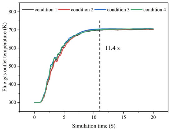
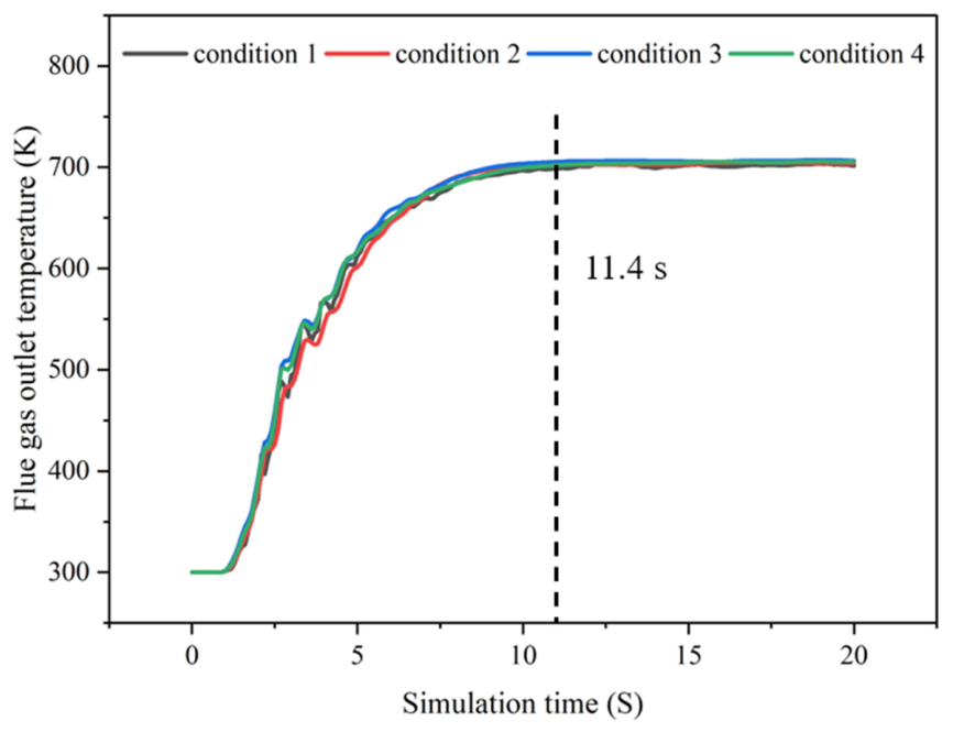
To verify whether the CPFD numerical simulation results reach a stable state, a temperature monitoring surface was set at the cyclone separator outlet, and the variation of the outlet flue gas temperature with simulation time was statistically analyzed, as shown in Figure 2.
Figure 2.
Variation in outlet flue gas temperature with time.
The results show that for all four conditions, after 11.4 s, the flue gas temperature at the cyclone separator outlet fluctuates slightly within a certain range but remains essentially unchanged, indicating that heat transfer has reached a steady state. Therefore, this study selects the steady-state simulation results after 12 s for numerical analysis.
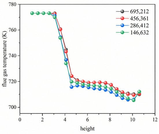
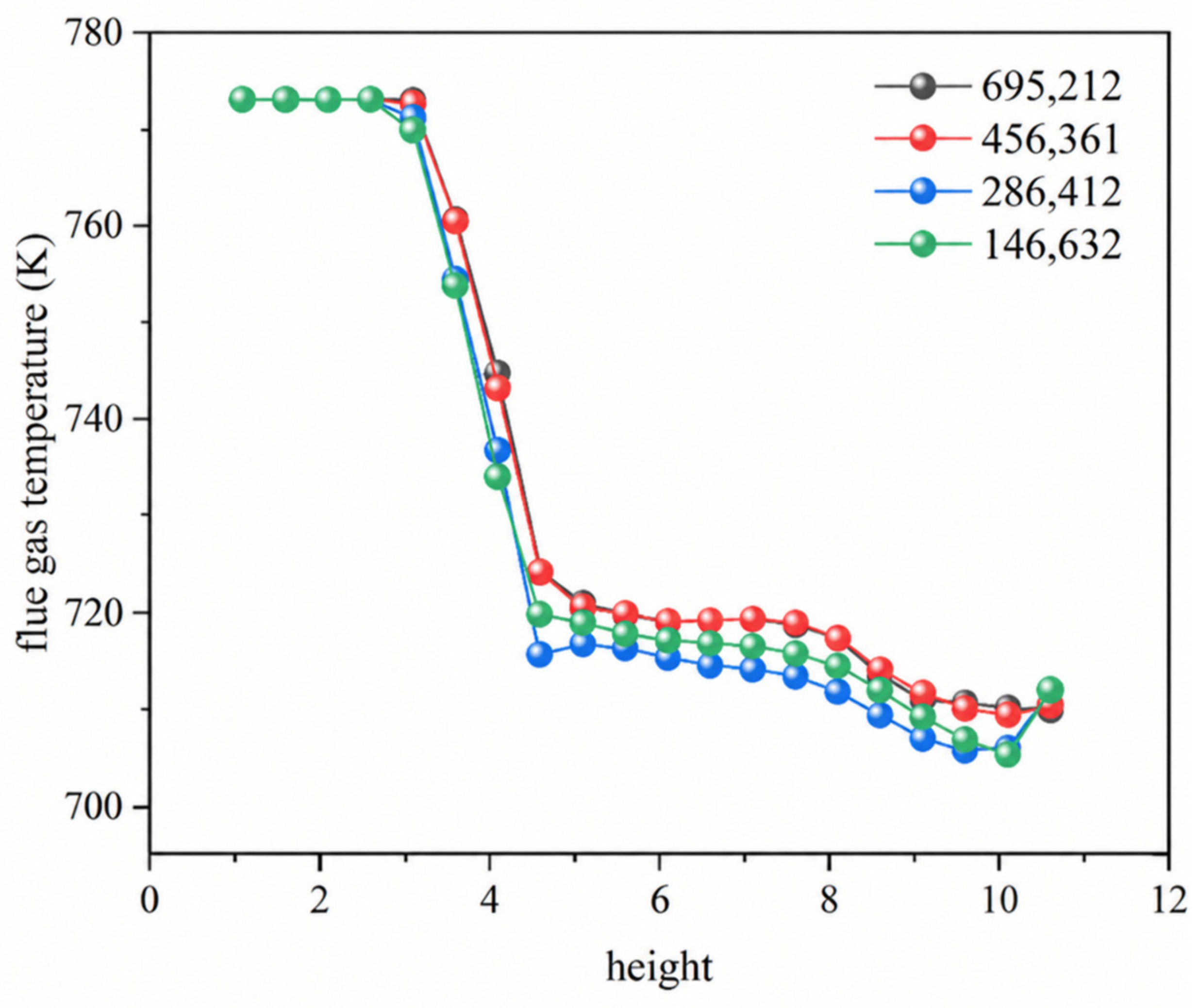
In the CPFD numerical simulation of a suspension preheater, the number of computational grids exerts a decisive influence on both solution accuracy and computational efficiency. To systematically evaluate the impact of grid count on simulation results, this study adopts four grid sizes—146,632, 286,412, 456,361, and 695,212—under Condition 3, and compares the steady-state average flue gas temperature along the height of the vertical riser. The results indicate that when the grid counts are 456,361 and 695,212, the flue gas temperature profiles exhibit good consistency, whereas larger deviations are observed for the grids of 146,632 and 286,412. Taking both computational accuracy and resource consumption into consideration, and while still ensuring reliability, this study ultimately selects 456,361 grids as the optimal mesh resolution for subsequent numerical simulations, as shown in Figure 3.
Figure 3.
Flue gas temperature variation along a vertical riser with grid number.
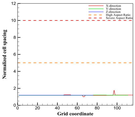
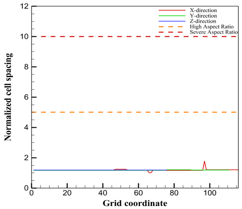
Following the grid-independence analysis, the quality of the selected computational grid was further evaluated using the grid-check function in Barracuda Virtual Reactor 24.0.0. As shown in Figure 4, the normalized cell spacing in the x-, y-, and z-directions remains close to unity over most of the computational domain, indicating a relatively uniform distribution of the computational cells. The maximum normalized spacing is approximately 1.8 in the x-direction, which is well below the high-aspect-ratio threshold of 5 and the severe-aspect-ratio threshold of 10. No significant grid-quality deterioration or abrupt variation in cell spacing is observed. These results indicate that the selected grid provides adequate spatial uniformity and resolution for the subsequent CPFD simulations.
Figure 4.
Grid quality evaluation based on normalized cell spacing.
3.5. Model Validation
To validate the accuracy of the numerical model developed in this study, a numerical simulation was performed based on the suspension preheater experimental setup reported in Ref. [41]. The simulation was conducted under the same operating conditions as the corresponding experimental case, with a gas flow rate of 0.0311 kg/s and a solid feed rate of 0.0201 kg/s. The simulated results were compared with the experimental data, as shown in Table 8. The relative errors of the fluid outlet temperature and particle outlet temperature were both less than 10% compared with the experimental results, with deviations of 4.02% and 4.59%, respectively. These results indicate good agreement between the numerical predictions and experimental measurements, demonstrating that the developed numerical model is reliable and accurate for predicting the performance of the suspension preheater.
Table 8.
Comparison between the simulated results and experimental data.
4. Results and Discussion
4.1. Gas–Solid Flow Characteristics
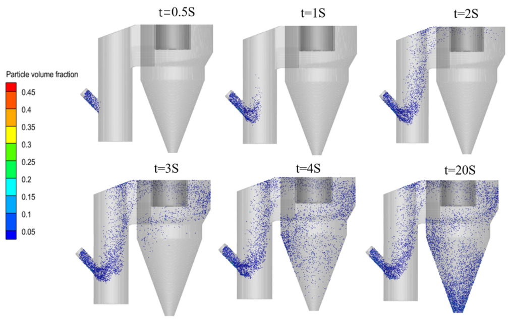
Gas–solid flow is the basis of particle heat transfer. To investigate whether millimeter-sized quartz sand particles can be effectively heated in a suspension preheating system, we analyze the time-dependent motion states of raw meal and three different sizes of quartz sand in the suspension preheating system, as shown in Figure 5. Different materials exhibit similar staged evolution characteristics of particle motion. Taking condition 2 as an example, within 0–0.5 s, particles entering from the virtual feed point rapidly rise into the riser under the action of the entrained air; within 0.5–1.0 s, due to gravity and residual initial velocity, particles undergo a brief sinking; after 1.0 s, the gas drag force regains dominance and particles move upward steadily with the gas flow; by 2.0 s, particles begin to enter the cyclone, and at 3.0 s, particles perform spiral motion along the wall under the action of centrifugal force, finally completing the transition from conveying to separation at 4.0 s. Throughout the process, particles go through four stages: acceleration, deceleration, re-acceleration, steady conveying, and centrifugal separation, with a total time of approximately 5 s.
Figure 5.
Variation in particle flow state with time.
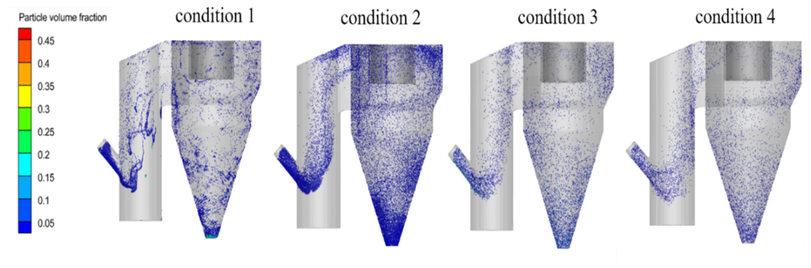
As the flow continues, as shown in Figure 6, Condition 1 using raw meal gradually exhibits partial agglomeration, while quartz sand particles show a more obvious wall-attachment phenomenon as the particle size increases. The underlying reason is that different particles exhibit different spatial distribution behaviors due to differences in physical properties and flow response characteristics. For raw meal particles, owing to their relatively high surface roughness and fine particle size, adhesion plays a dominant role, leading to the formation of high-concentration particle agglomerates in local regions. In contrast, quartz sand particles have better flow dispersibility; however, as the particle size increases, their inertia increases and the Stokes number rises, which reduces their ability to follow the gas flow. Consequently, the particles exhibit obvious wall-attachment behavior in the riser.
Figure 6.
Particle volume fraction distribution.
4.2. Heat Absorption Distribution in the Suspension Preheater
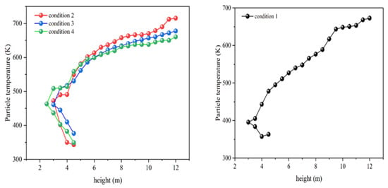
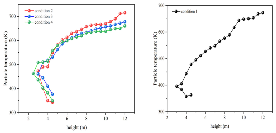
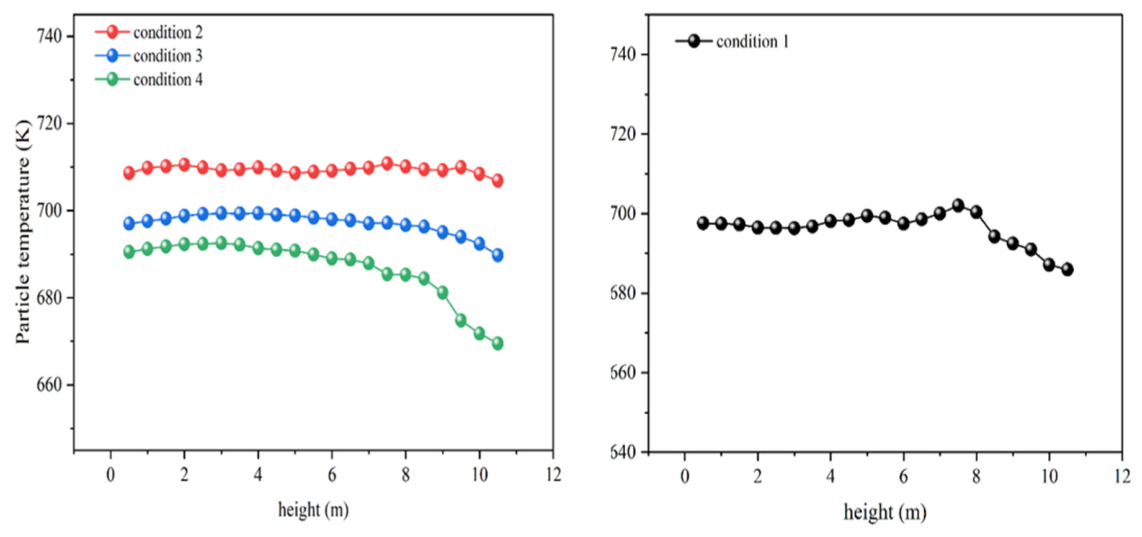
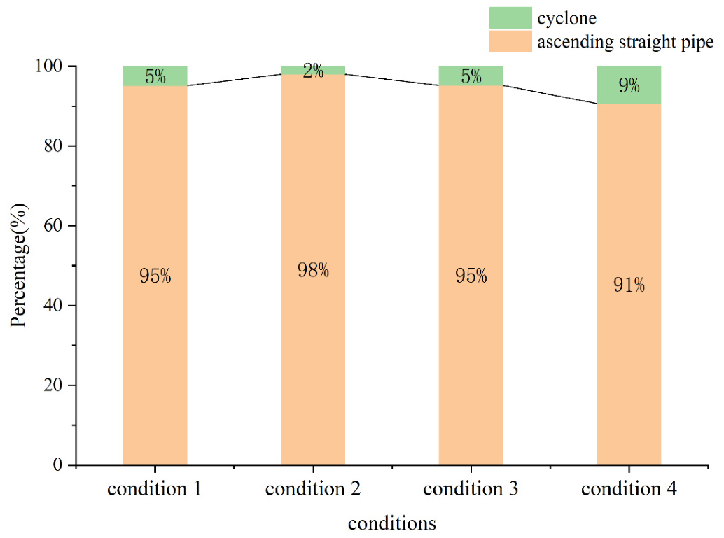
In the suspension preheater, material heating mainly occurs in two components: the riser and the cyclone separator. The heat absorption distribution in each section of the system is an important parameter for design and operation. The following analyzes the variation in particle temperature along the height direction in the riser (see Figure 7) and the cyclone separator (see Figure 8) under different working conditions. On this basis, the proportion of heat absorbed by particles in the riser and the separator is calculated.
Figure 7.
Variation in particle temperature along the height of the vertical riser.
Figure 8.
Variation in particle temperature along the height of the cyclone separator.
Figure 7 shows the variation in particle temperature along the height in the vertical riser for four different operating conditions. It can be seen that in the initial stage after feeding, the particle temperature fluctuates to a certain extent, then gradually increases and tends to level off. This phenomenon is mainly related to the adjustment of particle motion after entering the vertical riser and the heat transfer process between the gas and solid phases. After particles enter the vertical riser from the feed pipe, their motion state is significantly adjusted under the combined action of the feeding gas flow and the main flue gas flow. Because of the entrainment by the feeding gas flow and the effect of gravitational inertia, the particles first move in the direction opposite of the flue gas, reverse after descending to a certain height, and then gradually move upward with the flue gas. The 3.5–5 m region is where the feed pipe is located; the introduction of the feeding gas flow disturbs the local flow field and causes the temperature and velocity of the fed particles in this region to be readjusted, which ultimately manifests as a certain degree of fluctuation in particle temperature during the initial feeding stage. Subsequently, as the particles gradually enter the stable upward flow section, the gas–solid two-phase flow state tends to become stable. Because the particle inlet temperature is lower than that of the high-temperature flue gas, the particles continuously absorb heat from the flue gas through gas–solid convective heat transfer and radiative heat transfer during the upward movement, so the particle temperature gradually increases with the height of the vertical riser. As the temperature difference between the particles and the high-temperature flue gas gradually decreases, the heating rate of the particles gradually declines, and finally their temperature gradually approaches the flue gas temperature and tends to stabilize. The temperature variations along the flow path for quartz sand particles of different sizes are generally consistent, that is, as the particle size increases, the particle outlet temperature gradually decreases. This is mainly related to factors such as the particle specific surface area, particle inertia, and gas–solid slip velocity caused by the change in particle size. For a particle population of the same mass, a decrease in particle size usually means that the particles have a larger specific surface area per unit mass, thereby providing a larger gas–solid heat transfer area. Meanwhile, small particles have lower inertia, and their motion state is more easily affected by the gas-phase flow, which in turn changes the relative motion state between the gas and solid phases.
Compared with conditions 2, 3, and 4, which use quartz sand particles of different sizes, condition 1 uses actual raw meal particles, and its temperature response exhibits certain particularities. This is mainly because raw meal and quartz sand differ greatly in particle size, thermophysical parameters, and other aspects.
Figure 8 shows the temperature variation in particles after they enter the cyclone separator. It can be observed that when particles enter the cyclone separator from the vertical riser, their temperature is still lower than that of the high-temperature gas phase, indicating that there remains some potential for further temperature rise within the cyclone separator. In the cyclone separator, particles rotate with the gas flow, and gas–solid heat transfer continues. Therefore, as particles move from the inlet to the lower discharge region, they can continuously absorb heat from the high-temperature gas phase. It should be noted that the particle trajectories in the cyclone separator are complex, and the particle temperature is influenced not only by gas–solid heat transfer but also by factors such as particle concentration and agglomeration. Consequently, the axial temperature variation pattern differs from that in the vertical riser. Specifically, the gas temperature decreases along the downward height direction; moreover, the temperature distribution within the cyclone separator is non-uniform, and particle agglomeration occurs on the cyclone wall. These combined factors can lead to a decrease in the temperature of some particles [15,16].
From the perspective of the particle outlet temperature of the cyclone separator, quartz sand particles still exhibit a relatively obvious particle size effect, that is, the larger the particle size, the lower the outlet temperature. This indicates that during the entire conveying and heat exchange process from the vertical riser to the cyclone separator, particle size has a significant influence on the temperature of large particles. For raw meal particles, however, the cyclone separator outlet temperature is higher than that of 0.5 mm and 1.0 mm quartz sand particles. This result suggests that the temperature response of small raw meal particles cannot be explained solely by particle size, but is closely related to their own particle size distribution, particle agglomeration characteristics, and thermophysical parameters.
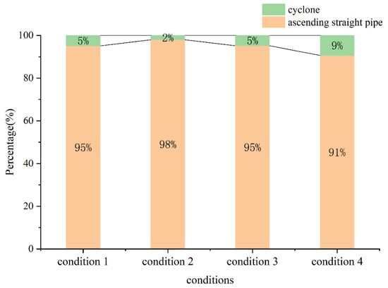
The results in Figure 9 indicate that the particle temperature rise is mainly concentrated in the vertical riser, while the particle temperature rise in the downstream cyclone is extremely limited. Moreover, as the particle size increases, the proportion of the particle temperature rise occurring in the vertical riser continuously decreases. Therefore, subsequent research will focus primarily on the heat transfer characteristics between particles and flue gas in the vertical riser.
Figure 9.
Contribution ratio of the separator section and the riser duct section to the overall particle temperature rise.
Overall, the variation in particle temperature in the suspension preheater is the result of the combined effects of particle size and size distribution, gas–solid relative motion, particle agglomeration behavior, and particle thermophysical properties. Among these factors, particle size mainly affects the effective heat transfer area between particles and the gas phase as well as the particle motion characteristics, while particle thermophysical properties further determine the temperature response of particles to the absorbed heat.
4.3. Temperature and Velocity Distributions of Flue Gas in the Vertical Riser
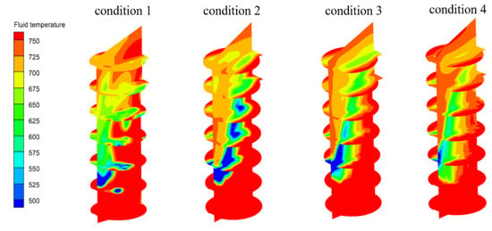
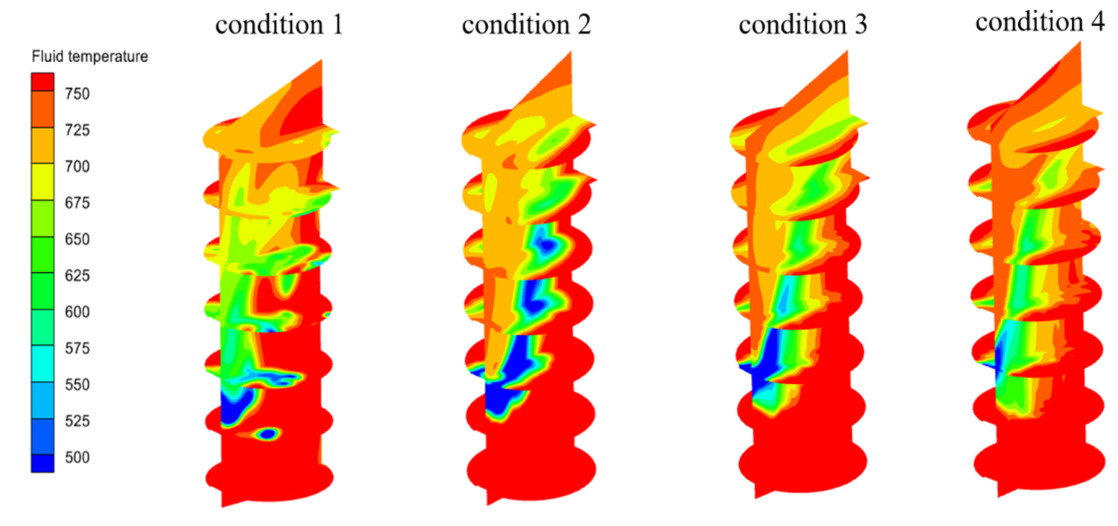
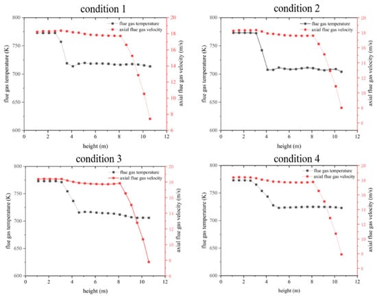
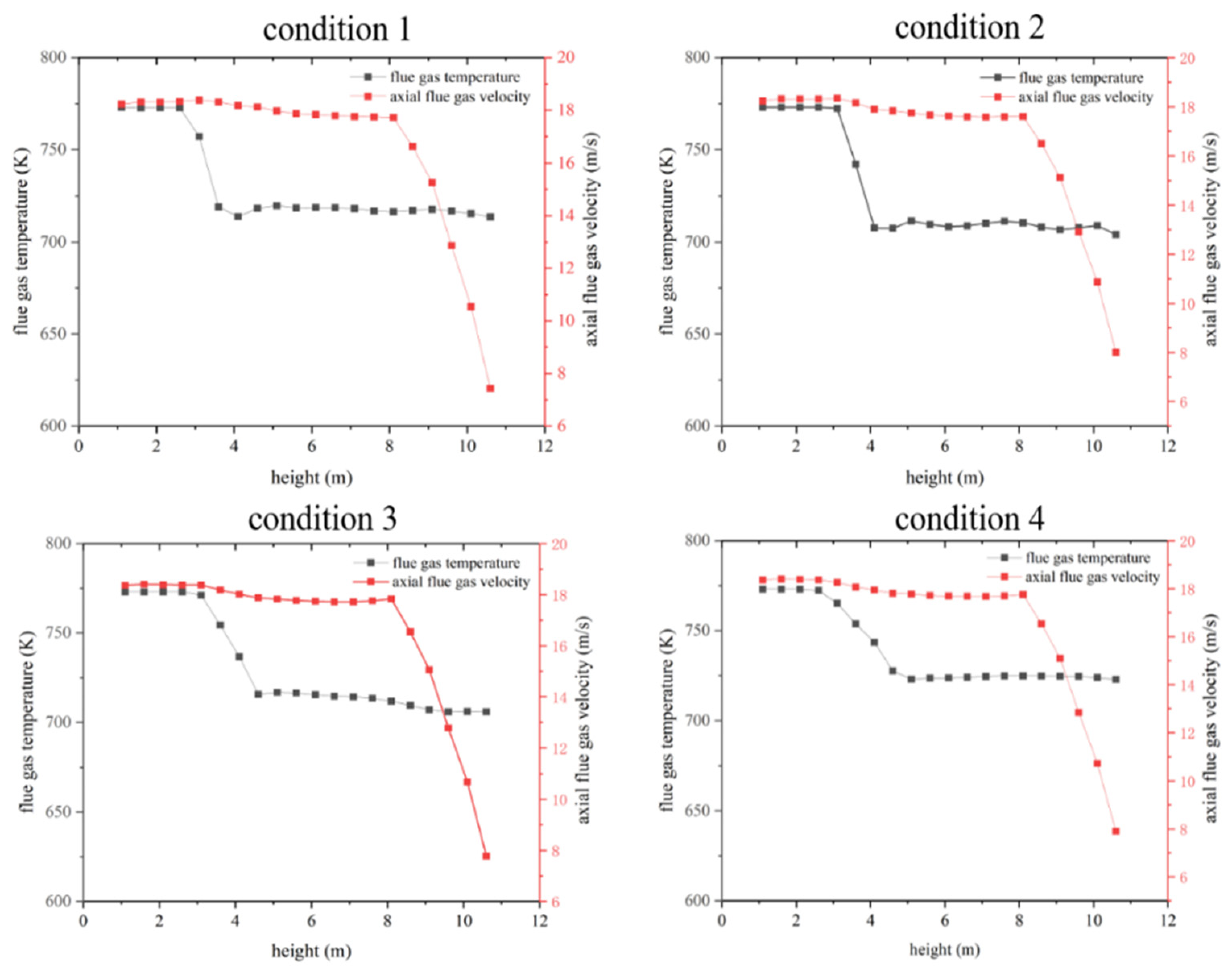
Figure 10 and Figure 11 show the variations in flue gas temperature and flue gas axial velocity along the height of the vertical riser. Along the axial height of the vertical riser, the flue gas temperature generally shows a gradual decreasing trend, and its axial velocity decreases correspondingly. Within the height range of 0–8 m from the inlet, the decreasing trends of flue gas temperature and axial velocity are in good agreement. When the height exceeds 8 m, the outlet of the vertical riser approaches the inlet of the cyclone separator, and the gas flow direction transitions from the originally axial-dominant flow to the tangential inlet condition, so the axial velocity continues to decrease. In addition, in the 4–5 m region, since this is the particle feed inlet, high-temperature carrier gas enters the system and causes a short-distance increase in the gas temperature at this location. After sufficient mixing, the temperature variation tends to become gentle and continues to maintain a decreasing trend.
Figure 10.
Flue gas temperature variation along the height of the riser duct.
Figure 11.
Variation in flue gas temperature and axial velocity along the riser duct height under different operating conditions.
On the other hand, by comparing the flue gas outlet temperatures of the vertical riser under the four operating conditions, conditions 2, 3, and 4 show a trend that the flue gas outlet temperature increases with increasing particle size, while the flue gas outlet temperature of condition 1 is higher than those of conditions 2 and 3 but lower than that of condition 4. Combined with the variation trend of particle outlet temperature described earlier, the higher the particle outlet temperature, the more heat the particles absorb from the flue gas, and therefore the lower the flue gas outlet temperature.
4.4. Particle Heat Transfer Coefficient and Slip Velocity
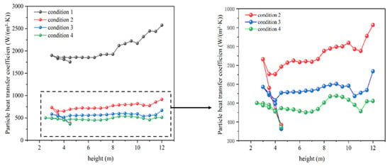
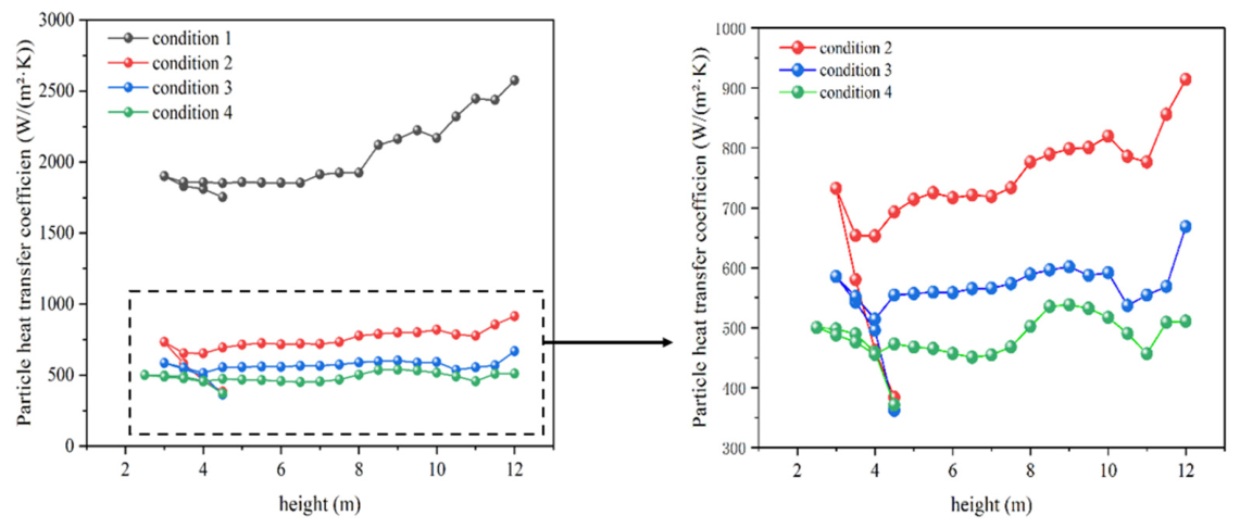
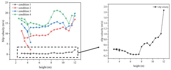
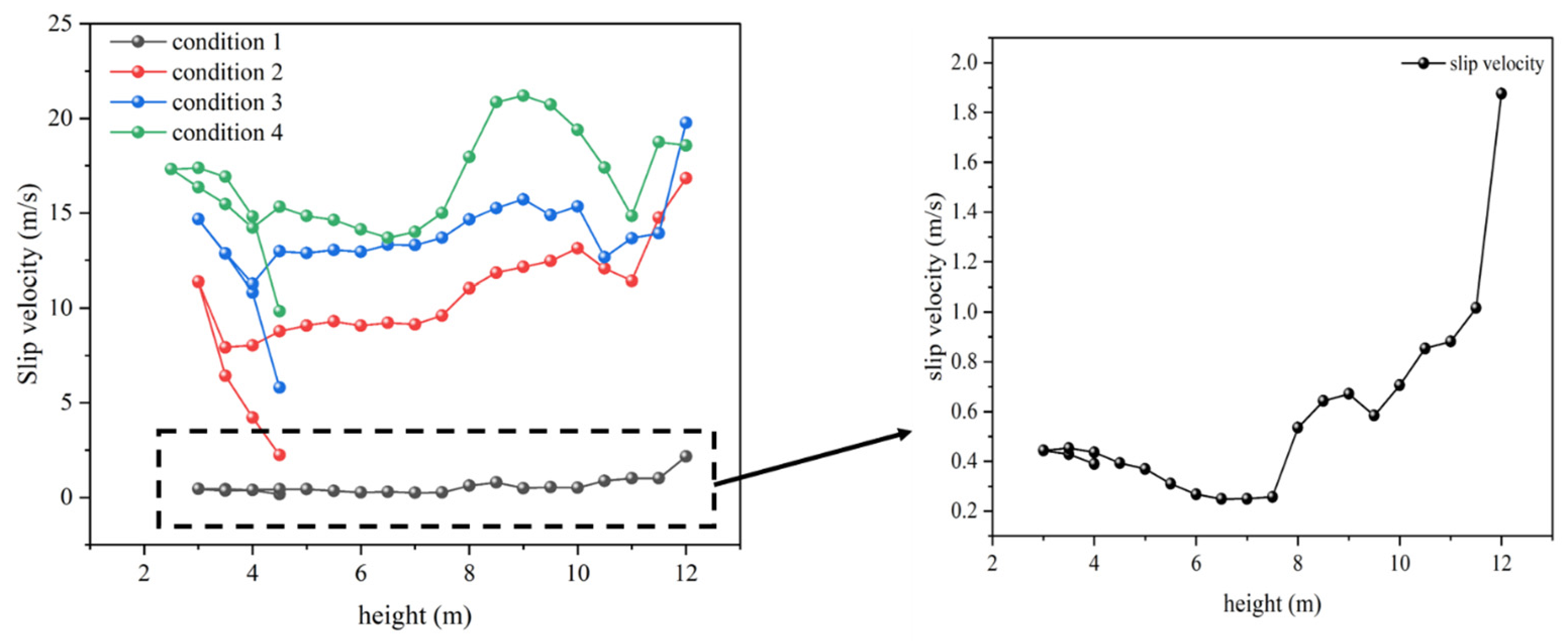
Figure 12 illustrates the variation in the gas–solid heat transfer coefficient along the height direction. For Condition 1, the overall trend of the heat transfer coefficient exhibits an initial increase, followed by a decrease, and then another increase. This variation pattern is consistent with the trend of particle slip velocity shown in Figure 13. The more pronounced fluctuation of the heat transfer coefficient under Condition 1 is primarily attributed to the smaller particle size of the raw meal particles, which renders the convective heat transfer coefficient highly sensitive to even minor changes in slip velocity. In contrast, the heat transfer coefficients under the other operating conditions show relatively stable variations. For quartz sand particles of the same material, an increase in particle size leads to a decrease in the heat transfer coefficient. Furthermore, for particles of the same size, the variation in the heat transfer coefficient is consistent with the trend of the gas–solid slip velocity.
Figure 12.
Particle heat transfer coefficient distribution along the riser duct height.
Figure 13.
Variation pattern of particle slip velocity along the height of the riser duct.
4.5. Pressure Distribution Along a Vertical Straight Rising Pipe
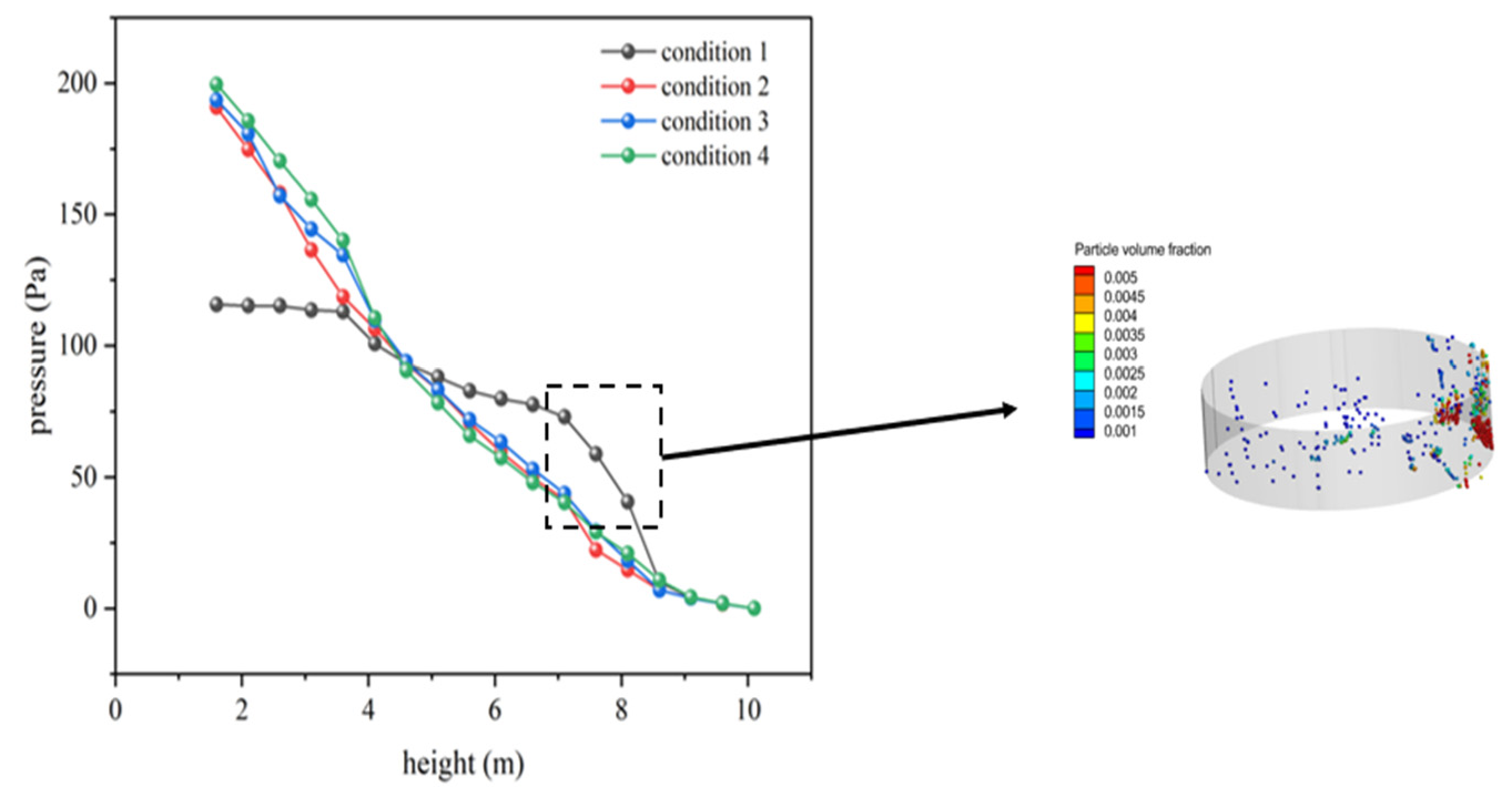
Figure 14 illustrates the variation in particle pressure along the height direction. It can be observed from the overall trend that the pressure in the vertical upward straight tube decreases progressively along the height direction. Under different operating conditions, the pressure variation exhibits a trend where larger particle sizes correspond to greater pressure changes. The underlying reason is that larger particles have a longer residence time in the riser tube, resulting in a greater accumulation of particles under the same feed rate. Under Condition 1, particle agglomeration occurs in the region of 7–8 m, which can also be reflected by the pressure variation in the figure. In the 3–5 m region, the pressure drops sharply due to the large amount of particles in this zone, which arises from the combined effect of particles injected downward from the inlet and particles moving upward after being suspended. Similar phenomena of pressure variation also exist in other operating conditions.
Figure 14.
Pressure variation along the height direction of a rising straight pipe.
5. Conclusions
In this study, a three-dimensional CPFD model based on the Barracuda software was developed to investigate the gas–solid flow and heat transfer characteristics in a suspension preheater for high-temperature solid particle thermal storage. To elucidate the effects of particle size, particle properties, gas–solid relative motion, and particle agglomeration on the heating performance, quartz sand particles with different sizes and cement raw meal were considered. The main conclusions are summarized as follows:
- (1)
- The staged evolution of particle motion in the suspension preheater was successfully reproduced. After entering the riser, particles successively undergo acceleration, deceleration, re-acceleration, stable upward conveying, and separation in the cyclone.
- (2)
- Particle size significantly influences particle flow behavior and spatial distribution. The fine raw meal particles exhibit local agglomeration due to their small size and strong interparticle adhesion. In contrast, quartz sand shows better flow dispersibility; however, the wall-attachment tendency becomes increasingly pronounced with increasing particle size.
- (3)
- Particle heating mainly occurs in the vertical riser rather than in the cyclone separator. After entering the riser, particles continuously absorb heat from the high-temperature flue gas, resulting in a gradual increase in particle temperature along the flow direction. As the particle temperature approaches the gas temperature, the temperature difference decreases and the heating rate gradually declines. For quartz sand, the particle outlet temperature decreases with increasing particle size.
- (4)
- The gas–solid heat transfer coefficient is closely related to particle slip velocity and particle size. For fine raw meal particles, the heat transfer coefficient exhibits more pronounced fluctuations. For quartz sand, the heat transfer coefficient is relatively stable and decreases with increasing particle size under the investigated conditions, and for particles of the same size, its variation follows the same trend as the gas–solid slip velocity.
- (5)
- The pressure in the vertical riser decreases gradually along the height direction, and larger particle sizes result in greater pressure drops, which is attributable to the longer residence time and greater accumulation of larger particles. In the case of raw meal particles, agglomeration occurs in the 7–8 m region, leading to locally high particle concentrations and a sharp pressure drop.
The above results fully validate the feasibility of applying multi-stage suspension heating technology for the direct heating of quartz sand solid particles using high-temperature flue gas, and provide a numerical basis for understanding the transport and heat transfer behavior of millimeter-scale thermal storage particles in a suspension preheater. Overall, the technical scheme of using a suspension preheater to heat millimeter-scale large-particle-size quartz sand is feasible; the substantial variation in particle size does not significantly affect the general trends of key parameters such as particle temperature, flue gas temperature, and gas–solid heat transfer coefficient along the flow path, indicating that this heating method exhibits good adaptability to variations in particle size.
Author Contributions
Writing—original draft preparation, C.W. Conceptualization, F.L. Resources, T.Z. Validation, H.Y. Investigation, X.J. Supervision, H.W. Writing—review and editing, M.Z. All authors have read and agreed to the published version of the manuscript.
Funding
This research was funded by Coal-Major Project 2026ZD1702301.
Data Availability Statement
The original contributions presented in this study are included in the article. Further inquiries can be directed to the corresponding author.
Conflicts of Interest
Xiaoguo Jiang is employed by Harbin Boiler Company Limited. The remaining authors declare that the research was conducted in the absence of any commercial or financial relationships that could be construed as a potential conflict of interest. The authors declare that this employment did not influence the design of the study, data collection, analysis, interpretation of results, writing of the manuscript, or the decision to submit the manuscript for publication. No other conflicts of interest are declared.
Nomenclature
| Governing equations Latin symbols | |
| CS | Smagorinsky subgrid-scale model constant. |
| DP | Particle drag coefficient (related to relative velocity). |
| F | Interphase momentum exchange source term (per unit volume). |
| FTp | Interphase heat exchange source term. |
| g | Gravitational acceleration vector. |
| hg | Gas-phase specific enthalpy. |
| Nup | Particle Nusselt number. |
| p | Fluid pressure (static). |
| Ps | Empirical constant for particle normal stress. |
| Prg | Gas-phase Prandtl number. |
| Rep | Particle Reynolds number (based on slip velocity and diameter). |
| Sij | Component of the fluid strain-rate tensor. |
| t | Time. |
| Tg | Gas temperature. |
| ug | Gas velocity vector. |
| up | Particle velocity vector. |
| Mean (or filtered) particle velocity. | |
| xp | Particle position vector. |
| Governing equations Greek symbols | |
| δij | Kronecker delta (unit tensor component). |
| Δ | Filter grid scale (characteristic length for LES). |
| εp | Particle volume fraction (solid fraction). |
| εcp | Packing limit volume fraction (maximum particle loading). |
| Θ | Granular temperature. |
| θg | Gas volume fraction (void fraction). |
| κeff | Gas effective thermal conductivity (molecular + turbulent). |
| μeff | Gas effective dynamic viscosity (molecular + turbulent). |
| μt | Gas turbulent eddy viscosity (subgrid-scale contribution). |
| ρg | Gas density. |
| ρp | Particle material density (true density). |
| τg/τgij | Gas viscous stress tensor (including turbulent effects). |
| τD | Particle momentum response relaxation time. |
| τP | Particle normal stress (from collisions/friction). |
| Drag models additional symbols | |
| D1 | Drag force term for the Wen-Yu model (per unit particle mass). |
| Cd | Drag coefficient (general). |
| rp | Particle radius. |
| D2 | Drag force term for the Ergun model (per unit particle mass). |
| C1, C2 | Constants in the Ergun model (C1 = 180,|C2 = 2). |
| D | Drag force term for the EMMS-Yang model (per unit particle mass). |
| fe | Correction factor in the EMMS-Yang model. |
| ω | Correction factor in the EMMS-Yang drag coefficient. |
| θf | Fluid (gas) volume fraction for high-void-fraction correction in ω. |
| μg | Gas dynamic viscosity (used in Reynolds number definitions). |
| Heat transfer and P-1 radiation additional symbols | |
| c(p,g) | Specific heat capacity of gas at constant pressure. |
| kg | Thermal conductivity of gas. |
| ReL | Reynolds number based on particle diameter (characteristic length). |
| dp | Particle diameter. |
| hl | Convective heat transfer coefficient (fluid-to-particle). |
| c0, c1, c2 | Empirical constants in the heat-transfer correlation. |
| n1 | Exponent in the heat-transfer correlation. |
| I | Diffusion coefficient for radiation (radiation diffusivity). |
| G | Incident radiation (irradiation). |
| a | Absorption coefficient of gas. |
| n | Refractive index. |
| σ | Stefan-Boltzmann constant. |
| Ep | Particle emission power (total emission term). |
| ap | Particle absorption coefficient (total). |
| Γ | Effective radiation diffusion coefficient (from P-1 model). |
| σp | Particle scattering coefficient (total). |
| np | Number of particles. |
| εpi | Emissivity of particle i. |
| Api | Surface area of particle i. |
| V | Volume (of computational cell or total volume). |
| fpi | Scattering albedo factor (or fraction) of particle i. |
| Tpi | Temperature of particle i. |
| Other Abbreviations | |
| CPFD | Computational Particle Fluid Dynamics |
| MP-PIC | Multiphase Particle-in-Cell |
| EMMS | Energy-Minimization Multi-Scale |
| LES | Large Eddy Simulation |
| P-1 | P-1 radiation model |
References
- Yi, Y.; Chang, L.; Wu, B.; Zhao, J.; Peng, H.; Li, L.; Wang, A. Life Cycle Assessment of Energy Storage Technologies for New Power Systems under Dual-Carbon Target: A Review. Energy Technol. 2024, 12, 2301129. [Google Scholar] [CrossRef] [Scilit]
- Zhang, N.; Dai, H.; Wang, Y.; Zhang, Y.; Yang, Y. Power system transition in China under the coordinated development of power sources, network, demand response, and energy storage. WIREs Energy Environ. 2021, 10, e392. [Google Scholar] [CrossRef] [Scilit]
- Liu, Y.; He, Q.; Shi, X.; Zhang, Q.; An, X. Energy storage in China: Development progress and business model. J. Energy Storage 2023, 72, 108240. [Google Scholar] [CrossRef] [Scilit]
- Yong, Q.; Tian, Y.; Qian, X.; Li, X. Retrofitting coal-fired power plants for grid energy storage by coupling with thermal energy storage. Appl. Therm. Eng. 2022, 215, 119048. [Google Scholar] [CrossRef] [Scilit]
- Fang, F.; Sun, Y.; Zhang, Y.; Du, M.; Liu, J. Dynamic modeling and performance analysis of a coal-fired power plant integrated with flue gas-molten salt thermal energy storage system. Appl. Therm. Eng. 2025, 280, 128348. [Google Scholar] [CrossRef] [Scilit]
- Ma, T.; Li, Z.; Lv, K.; Chang, D.; Hu, W.; Zou, Y. Design and performance analysis of deep peak shaving scheme for thermal power units based on high-temperature molten salt heat storage system. Energy 2024, 288, 129557. [Google Scholar] [CrossRef] [Scilit]
- Bell, S.; Steinberg, T.; Will, G. Corrosion mechanisms in molten salt thermal energy storage for concentrating solar power. Renew. Sustain. Energy Rev. 2019, 114, 109328. [Google Scholar] [CrossRef] [Scilit]
- Sun, W.; Zhang, Z.; Zhang, Z.; He, N.; Wei, Q.; Feng, L.; Wang, Z.; Wu, J.; Liu, C.; Fu, S.; et al. Photothermal phase change material microcapsules via cellulose nanocrystal and graphene oxide co-stabilized Pickering emulsion for solar and thermal energy storage. Sci. China Mater. 2024, 67, 3225–3235. [Google Scholar] [CrossRef] [Scilit]
- Ma, Z.; Glatzmaier, G.C.; Mehos, M. Development of Solid Particle Thermal Energy Storage for Concentrating Solar Power Plants that Use Fluidized Bed Technology. Energy Procedia 2014, 49, 898–907. [Google Scholar] [CrossRef] [Scilit]
- Davenport, P.; Ma, Z.; Schirck, J.; Nation, W.; Morris, A.; Wang, X.; Lambert, M. Characterization of solid particle candidates for application in thermal energy storage and concentrating solar power systems. Sol. Energy 2023, 262, 111908. [Google Scholar] [CrossRef] [Scilit]
- Lin, Q.; Wu, Y.; Lv, L.; Liu, X.; Chen, C.; Lan, Z.; Zhou, H. Simulated performance of electric heating solid particle thermal storage devices. Appl. Therm. Eng. 2026, 296, 130748. [Google Scholar] [CrossRef] [Scilit]
- Lin, Q.; Chen, C.; Lan, Z.; Li, H.; Zhou, H. A study on the optimization of thermal performance for an electrically heated solid-particle thermal energy storage device. Int. J. Heat Mass Transf. 2026, 271, 129264. [Google Scholar] [CrossRef] [Scilit]
- Mehrtash, M.; Polat Karadiken, E.; Tari, I. A Combined Experimental and Numerical Thermo-Hydrodynamic Investigation of High-Temperature Fluidized-Bed Thermal Energy Storage. Processes 2022, 10, 1097. [Google Scholar] [CrossRef] [Scilit]
- Ji, Z.; Song, G.; Tang, Z.; Sun, L. Effect of Air Distribution on the Transport Characteristics of Solid Particles in the Thermal Storage and Release System of Circulating Fluidized Bed. J. Therm. Sci. 2024, 33, 1554–1563. [Google Scholar] [CrossRef] [Scilit]
- Zhang, H.; Dewil, R.; Degrève, J.; Baeyens, J. The design of cyclonic pre-heaters in suspension cement kilns. Int. J. Sustain. Eng. 2014, 7, 307–312. [Google Scholar] [CrossRef] [Scilit]
- Worrell, E.; Kermeli, K.; Galitsky, C. Energy Efficiency Improvement and Cost Saving Opportunities for Cement Making: An ENERGY STAR Guide for Energy and Plant Managers; Report No. 430-R-13-009; U.S. Environmental Protection Agency: Washington, DC, USA, 2013. Available online: https://www.energystar.gov/sites/default/files/buildings/tools/ENERGY%20STAR%20Guide%20for%20the%20Cement%20Industry%2028_08_2013%20Final.pdf (accessed on 6 October 2026).
- Hu, D.; Gu, D.; Li, C. Research on working principle of Krupp (shaft) preheater. J. Chin. Ceram. Soc. 1987, 15, 97–105. [Google Scholar]
- Cai, J.; Wu, H.; Ren, Q.; Lin, L.; Zhou, T.; Lyu, Q. Innovative NOx reduction from cement kiln and pilot-scale experimental verification. Fuel Process. Technol. 2020, 199, 106306. [Google Scholar] [CrossRef] [Scilit]
- Gao, M.; Song, G.; Song, W.; Liu, J. Research progress on high-temperature flue gas heating in solid particle thermal energy storage technology. Energy Storage Sci. Technol. 2026, 15, 1054–1072. [Google Scholar] [CrossRef]
- Qi, A.; Liu, J.; Huang, Y.; Song, G.; Zhu, J.; Liu, Y.; Lyu, Q. Progress on high-temperature solid particle thermal energy storage coupled with deep flexible peak regulation technology for coal-fired power units. Energy Storage Sci. Technol. 2026, 15, 3225–3243. [Google Scholar]
- Wasilewski, M.; Anweiler, S.; Masiukiewicz, M. Characterization of multiphase gas–solid flow and accuracy of turbulence models for lower stage cyclones used in suspension preheaters. Chin. J. Chem. Eng. 2019, 27, 1618–1629. [Google Scholar] [CrossRef] [Scilit]
- Kashani, E.; Mohebbi, A.; Heidari, M.G. CFD simulation of the preheater cyclone of a cement plant and the optimization of its performance using a combination of the design of experiment and multi-gene genetic programming. Powder Technol. 2018, 327, 430–441. [Google Scholar] [CrossRef] [Scilit]
- Córcoles, J.I.; Díaz-Heras, M.; Fernández-Torrijos, M.; Almendros-Ibáñez, J.A. Flow and heat transfer analysis of a gas–particle fluidized dense suspension in a tube for CSP applications. Renew. Energy 2023, 206, 1–12. [Google Scholar] [CrossRef] [Scilit]
- Córcoles, J.I.; Acosta-Iborra, A.; Almendros-Ibáñez, J.A. Influence of immersed surface shape on the heat transfer process and flow pattern in a fluidized bed using numerical simulation. Int. J. Heat Mass Transf. 2021, 178, 121621. [Google Scholar] [CrossRef] [Scilit]
- Liang, Y.; Zhang, Y.; Li, T.; Lu, C. A critical validation study on CPFD model in simulating gas–solid bubbling fluidized beds. Powder Technol. 2014, 263, 121–134. [Google Scholar] [CrossRef] [Scilit]
- Snider, D.M. An Incompressible Three-Dimensional Multiphase Particle-in-Cell Model for Dense Particle Flows. J. Comput. Phys. 2001, 170, 523–549. [Google Scholar] [CrossRef] [Scilit]
- He, L.; Cheng, Y.; Qin, Q.; Zhao, X.; Guo, C.Y.; Liang, Y. CPFD simulation on particle behaviour in an entrained-flow gasifier. Clean Energy 2020, 4, 75–84. [Google Scholar] [CrossRef] [Scilit]
- Medina-Pedraza, C.; de Lasa, H. Hybrid Particle Cluster CPFD Simulation in the Acceleration and Stabilized Sections of a Downflow Circulating Fluidized Bed. Ind. Eng. Chem. Res. 2020, 59, 20325–20336. [Google Scholar] [CrossRef] [Scilit]
- Chen, C.; Werther, J.; Heinrich, S.; Qi, H.-Y.; Hartge, E.-U. CPFD simulation of circulating fluidized bed risers. Powder Technol. 2013, 235, 238–247. [Google Scholar] [CrossRef] [Scilit]
- Lanza, A.; Islam, M.A.; de Lasa, H. CPFD modeling and experimental validation of gas–solid flow in a down flow reactor. Comput. Chem. Eng. 2016, 90, 79–93. [Google Scholar] [CrossRef] [Scilit]
- Snider, D.M.; Clark, S.M.; O’Rourke, P.J. Eulerian–Lagrangian method for three-dimensional thermal reacting flow with application to coal gasifiers. Chem. Eng. Sci. 2011, 66, 1285–1295. [Google Scholar] [CrossRef] [Scilit]
- Smagorinsky, J. General circulation experiments with the primitive equations: I. The basic experiment. Mon. Weather Rev. 1963, 91, 99–164. [Google Scholar] [CrossRef] [Scilit]
- Andrews, M.J.; O’Rourke, P.J. The Multiphase Particle-in-Cell (MP-PIC) Method for Dense Particulate Flows. Int. J. Multiph. Flow 1996, 22, 379–408. [Google Scholar] [CrossRef] [Scilit]
- Nakhaei, M.; Hessel, C.E.; Wu, H.; Grévain, D.; Zakrzewski, S.; Jensen, L.S.; Glarborg, P.; Dam-Johansen, K. Experimental and CPFD study of gas–solid flow in a cold pilot calciner. Powder Technol. 2018, 340, 99–115. [Google Scholar] [CrossRef] [Scilit]
- Wen, C.Y.; Yu, Y.H. A generalized method for predicting the minimum fluidization velocity. AIChE J. 1966, 12, 610–612. [Google Scholar] [CrossRef] [Scilit]
- Pei, Y.; Wang, Y.; Zhang, X.; Li, D.; Dong, N.; Ma, J.; Wang, Q. Simulation of Oxygen-Enriched Combustion Characteristics of Different Biomass Circulating Fluidized Beds Based on CPFD Model. Processes 2026, 14, 2124. [Google Scholar] [CrossRef] [Scilit]
- Yang, N.; Wang, W.; Ge, W.; Wang, L.; Li, J. Simulation of Heterogeneous Structure in a Circulating Fluidized-Bed Riser by Combining the Two-Fluid Model with the EMMS Approach. Ind. Eng. Chem. Res. 2004, 43, 5548–5561. [Google Scholar] [CrossRef] [Scilit]
- Song, F.; Li, F.; Wang, W.; Li, J. A sub-grid EMMS drag for multiphase particle-in-cell simulation of fluidization. Powder Technol. 2018, 327, 420–429. [Google Scholar] [CrossRef] [Scilit]
- Barahmand, Z. Design of an Industrial Chlorination Reactor Using CPFD Simulations. Master’s Thesis, University of South-Eastern Norway, Notodden, Norway, 2021. [Google Scholar]
- Díaz-Heras, M.; Córcoles, J.I.; Belmonte, J.F.; Almendros-Ibáñez, J.A. 3D numerical simulation of a directly irradiated bubbling fluidized bed with SiC particles. Appl. Therm. Eng. 2021, 190, 116812. [Google Scholar] [CrossRef] [Scilit]
- Popuri, A.K.; Garimella, P. Hydrodynamic and Heat Transfer Studies in Riser System for Waste Heat Recovery using Limestone. J. Eng. Sci. Technol. 2018, 13, 1793–1804. [Google Scholar]


Disclaimer/Publisher’s Note: The statements, opinions and data contained in all publications are solely those of the individual author(s) and contributor(s) and not of MDPI and/or the editor(s). MDPI and/or the editor(s) disclaim responsibility for any injury to people or property resulting from any ideas, methods, instructions or products referred to in the content. |
© 2026 by the authors. Licensee MDPI, Basel, Switzerland. This article is an open access article distributed under the terms and conditions of the Creative Commons Attribution (CC BY) license.