


Abstract
Structural assessment of customized 3D-printed prosthetic sockets requires a basis for selecting geometries and loading relevant socket regions. This study explored a population-informed assessment framework combining statistical shape sampling with mock limb material comparisons. A statistical shape model (SSM) was reconstructed from 67 archived records of liner-covered residual limbs. Geometries at the empirical 2.5th, 50th, and 97.5th percentiles of the first principal component guided socket design; mock limbs matched the socket inner surfaces. Nine finite element cases compared aluminum, a muscle-inspired surrogate, and a bulk soft-tissue surrogate under 4480 N loading based on ISO 10328 condition I at level P5. At the 2.5th, 50th, and 97.5th percentiles, trimline maxima were 1.0, 1.5, and 0.7 MPa for aluminum; 16.0, 12.4, and 3.9 MPa for the muscle-inspired surrogate; and 19.7, 14.1, and 3.9 MPa for the bulk surrogate. Whole-socket peaks shifted from the distal attachment with aluminum to the anterior trimline with compliant surrogates in two geometries; all materials produced distal peaks in the 97.5th-percentile geometry. These findings support combining patient-derived shape sampling with explicit mock limb specification for regional socket assessment. Shape percentiles describe observed variation rather than worst-case strength conditions. The framework may inform complementary test configurations, but failure prediction and product assurance require broader assessment and physical validation.
1. Introduction
Three-dimensionally (3D) printed transtibial prosthetic sockets enable individualized geometry, but their structural assessment requires a reproducible basis for selecting test specimens and loading them. ISO 10328 provides procedures for structural testing of lower-limb prostheses, including static and cyclic loading; socket-specific aspects such as mock residual limb shape and composition remain incompletely defined [1,2]. Its established loading configurations therefore offer a practical starting point for socket assessment, provided these additional test conditions are specified. Variation in manufacturing and test methods across published studies [3], together with effects of printing orientation [4], further complicates comparisons.
Individualized geometry makes it necessary to specify which range of socket designs a structural test is intended to represent. Here, a design envelope denotes the stated range of permitted device geometry and other relevant design and manufacturing parameters. Developing structural product assurance within such an envelope requires both a rationale for selecting test geometries and test conditions that load the regions of interest. The present work addresses the shape-sampling component of this problem and the internal support conditions supplied by the mock residual limb, with a common socket design procedure and loading protocol.
Recent patient-specific design studies have linked digital geometry to clinical assessment. Lee et al. (2024) used imaging and finite element analysis to design custom liner–socket interfaces and compared them with conventional interfaces for nine residual limbs in eight participants, evaluating gait, pressure, temperature, and reported comfort [5]. Van der Stelt et al. (2025) developed an artificial-intelligence socket-shape prediction method from 116 patient records and assessed fit and comfort in a ten-participant clinical comparison [6]. These studies illustrate progress toward individualized fit. Mbithi et al. (2025) used an SSM of residual limb shape and a dataset of 163 limb–socket pairs to predict individualized socket modifications, followed by a clinical comparison involving 17 participants and 19 residual limbs [7]. Their evaluation focused on socket comfort and patient experience, illustrating how population shape information can support clinical design. Structural assessment poses a complementary question: which geometries and internal support conditions should be tested to assess socket-wall loading across a specified range of customized products?
Geometric parameter studies offer a complementary basis for understanding socket mechanics. Silver-Thorn and Childress varied residual limb length and taper in a generic finite element model to examine interface stresses [8]. More recently, Baharuddin et al. (2026) evaluated tibial lengths of 12.5, 15, and 17.5 cm, together with distal bevel angles and tissue stiffness, in a model based on one volunteer [9]. These were numerical investigations of limb-interface mechanics, rather than socket structural qualification tests. Such prescribed dimensional changes help isolate mechanical influences; they do not, by themselves, describe how length and contour covary in a patient dataset.
Identifying geometric factors that strongly affect stress can guide test selection, but mechanical sensitivity alone does not establish how much of the shape variation observed in patients is represented. Patient-derived geometry is therefore also needed to relate test specimens to the intended population. Statistical shape modelling (SSM) describes observed variation and provides an explicit basis for sampling shapes. In an SSM, changing a component score changes the surface according to a spatial pattern learned from the dataset, retaining the coupled shape changes described by that mode rather than altering one dimension independently. This supplies an anatomical rationale for candidate test geometries, without establishing their mechanical severity. OpenLimbTT provides population-derived transtibial shape models for simulation and design; its principal modes describe variations including residual limb length and soft-tissue profile, and its leave-one-out assessment examines the stability of these modes [10]. Such models make anatomical sampling reproducible, while their application to structural testing still requires decisions about socket construction and load transfer. Shahapurkar et al. considered scanning and SSM alongside material selection in developing an anthropomorphic mock residual limb [11]. The AOPA Socket Guidance Workgroup also proposed SSM-based shape selection for socket testing [2]. Principal components describe variance in shape; they do not rank strength sensitivity or identify worst-case designs.
Test conditions also need to load regions where socket fractures have been reported. Kim et al. (2024) used an aluminum mock residual limb with a 3 mm gel liner under ISO 10328 condition II and reported failure at the distal socket or pyramid attachment [12]. In clinical follow-up, van der Stelt et al. (2022) reported fractures around the patellar-tendon and popliteal trimline regions in active users of 4 mm fused filament fabrication (FFF)-printed sockets [13]. These studies differed in loading, design, manufacture, and use history, so their failure locations cannot be attributed to mock limb stiffness alone. They nevertheless motivate examining whether mock limb properties redistribute loading between the distal attachment and trimline.
Finite element analysis enables controlled comparisons of these support conditions across selected geometries. Population-based modelling by Steer et al. combined residual limb morphology, tissue compliance, and socket design to predict interface pressure, shear, and subdermal strain [14]. This established a basis for exploring anatomical variation in computational biomechanics. The structural testing question addressed here concerns stress in the socket wall and attachment, and how the mock limb used to apply a test load changes that response. Steer et al. demonstrated that material, friction, and loading assumptions affect predictions at the residuum–socket interface [15]. For socket structural performance, Rajashekar et al. (2026) combined material fatigue measurements, finite element analysis, and physical socket testing, identifying the distal region as susceptible to fatigue failure in a printed ABS socket [16]. This illustrates the role of experimental comparison in evaluating structural predictions for a specified socket construction. For structural assessment, the question is whether a specified mock limb representation loads the relevant socket regions consistently across geometries. Evaluating stresses at previously reported fracture regions can inform test design, while a change in stress concentration alone does not establish a fracture mechanism or a failure load.
Together, these studies support individualized design, population shape description, and computational assessment, but a reproducible structural testing framework must connect two choices explicitly: which patient-derived geometries to sample, and which mock limb properties to use when loading them. The present contribution is a controlled comparison of these choices under a common protocol, linking statistical shape sampling to regional socket-wall and attachment stresses. Statistical percentiles specify the sampled anatomy; they are not assumed to determine tissue stiffness, load-bearing capacity, or all mechanically relevant design conditions.
This study investigates a population-informed framework for structural assessment of 3D-printed sockets by combining SSM-based shape selection with mock limb material comparisons under loading based on ISO 10328. Three geometries selected at empirical percentiles of the first principal component (PC1) informed socket design. Mock limbs constructed from the socket inner surfaces were assigned aluminum or one of two compliant material representations. The nine-case comparison evaluated regional von Mises stresses and whole-socket peak locations. The objective was to examine how mock limb material changes regional socket loading across statistically selected shapes and thereby inform the selection of complementary structural test conditions.
2. Materials and Methods
2.1. Study Design and Source Geometry
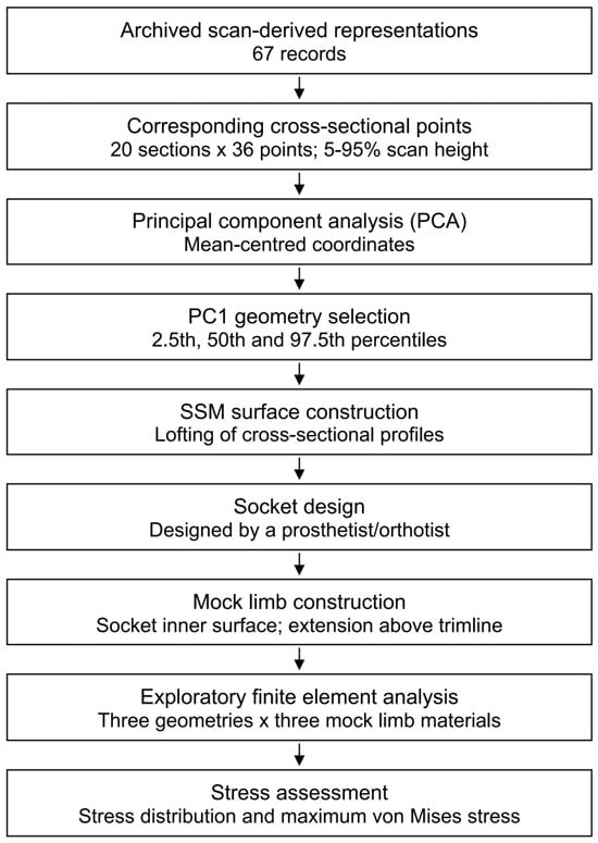
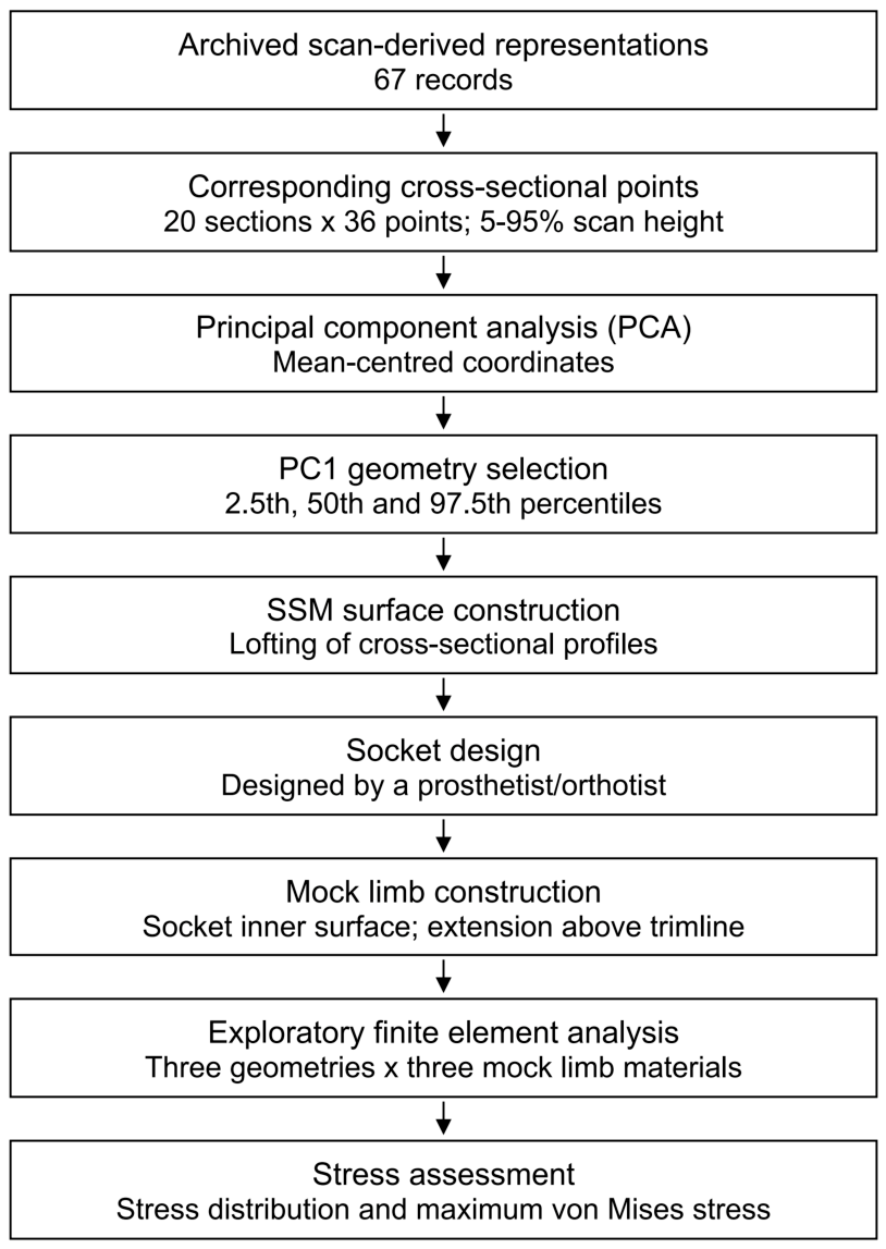
The proposed framework combined patient-derived shape sampling with comparisons of mock limb support conditions and regional socket stresses. This initial implementation used statistical shape reconstruction to select source geometries and finite element analysis to compare three mock limb materials within each socket assembly. Figure 1 summarizes the workflow. No physical socket testing or experimental validation was included.
Figure 1.
Workflow for the proposed structural assessment framework, linking statistical shape sampling to socket design, construction of matching mock limbs, and regional stress comparison under a common loading protocol. Three socket and mock limb geometries, each evaluated with three material representations, yielded nine cases. SSM, statistical shape model; PCA, principal component analysis; PC1, first principal component.
The shape model used 67 archived scan-derived representations of liner-covered residual limbs from adults with unilateral transtibial amputation in the Philippines. The dataset was restricted to this transtibial cohort; other amputation levels were not represented. It was used to describe variation within the archived records, without establishing anatomical representativeness across patient populations. Right residual limbs had been mirrored to the left side in the historical preprocessing. This study was conducted in accordance with the Declaration of Helsinki and was approved by the Institutional Ethics Committee of Shibaura Institute of Technology (approval code: 25-016). Written informed consent was obtained from all participants prior to their inclusion in this study. This approval covered secondary analysis of the 67 archived scan-derived records.
Residual limb surface geometry was acquired using a Sense Pro 3D scanner (Guangzhou Kangke 3D Digital Technology Co., Ltd., Guangzhou, China; scanning method, structured light; nominal accuracy, 0.3 mm). During shape acquisition, participants wore a liner, and bony landmarks and the mid-patellar-tendon (MPT) reference level were marked on the liner surface. Because flexion contracture and the global orientation of the residual limb are morphological features that may influence socket fit [14,17], the residual limb was not mechanically straightened during scanning. Each limb was instead scanned while preserving its habitual posture.
2.2. Statistical Shape Representation and Geometry Selection
Coordinates are reported with Z as the longitudinal axis and XY transverse planes. The archived Y and Z coordinate labels were interchanged for reporting and visualization without altering the fitted shapes. The MPT reference level for the SSM-derived models was defined from the markings made during scanning. No additional translation to the mid-patellar-tendon (MPT) level or fixed MPT-referenced proximal cut was applied to the archived points.
Twenty sections per scan were equally spaced between 5% and 95% of the preprocessed surface height, measured from minimum to maximum Z. Thus, section indices represented relative scan height, not common anatomical levels, and physical spacing varied between records.
The upper sampling boundary of the SSM source geometry followed source scan extent, without artificial extension or a fixed MPT offset, and did not define a clinical trimline. Given reported regional differences in cast rectification [18], relative scan height need not identify equivalent anatomy across records.
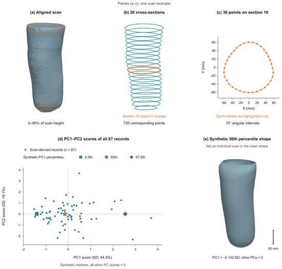
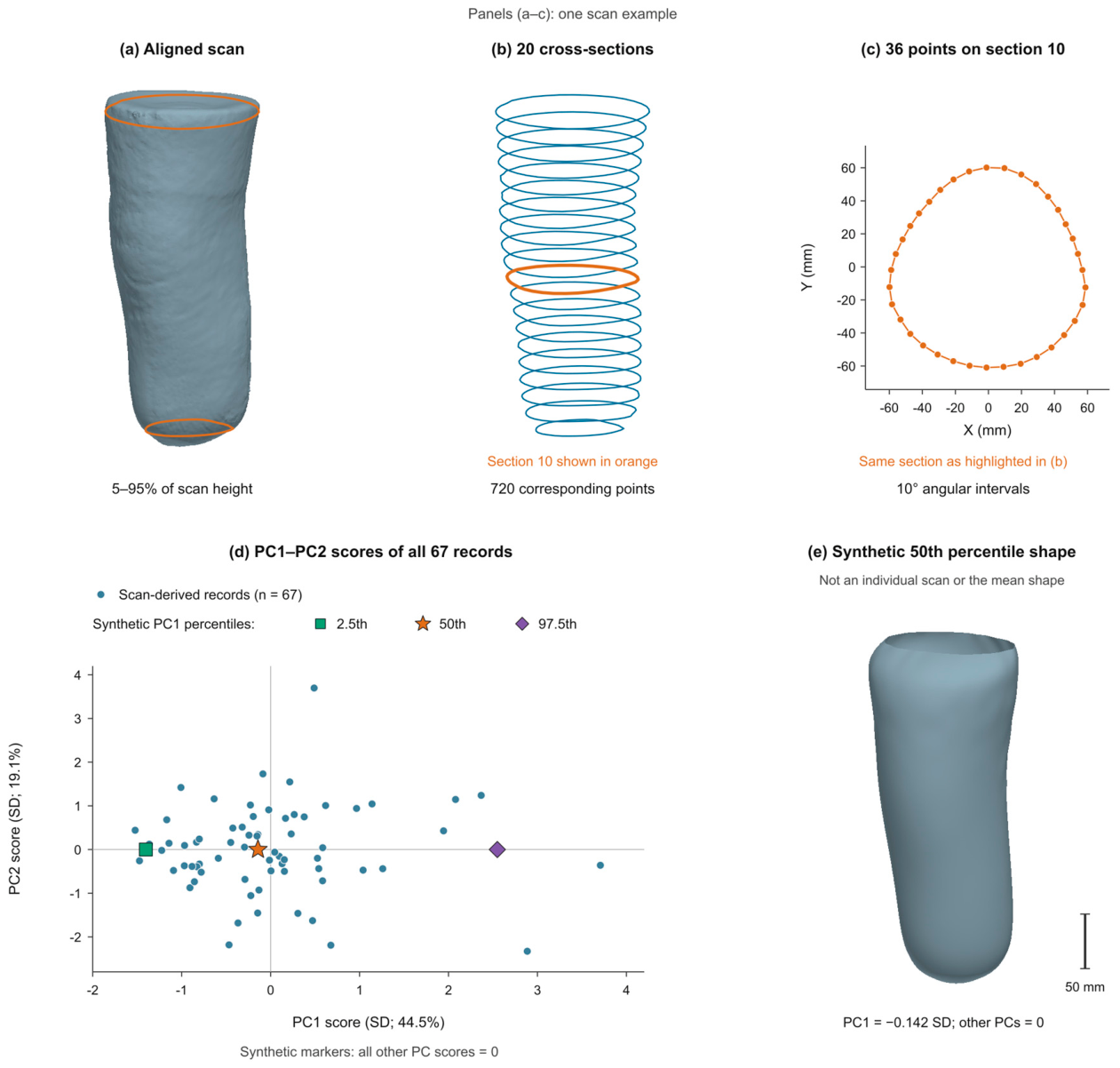
Each shape contained 20 sections of 36 points sampled at nominal 10-degree intervals about each section center. Concatenating XYZ coordinates in section and circumferential order yielded 720 points and 2160 variables. Figure 2a–c illustrates one scan. Correspondence followed section index and angle, not non-rigid registration of a common mesh. Kon et al. [19] described related cross-sectional modelling approaches.
Figure 2.
From scan-derived geometry to a statistical shape representation. (a) An aligned scan with the sampling limits at 5% and 95% of scan height. (b) Twenty transverse sections, with Section 10 highlighted in orange. (c) Thirty-six corresponding points on the same highlighted section. Panels (a–c) show the same scan example; in the reported coordinate convention, the longitudinal axis is Z, and sections lie in XY planes. (d) PC1 and PC2 scores for all 67 records, expressed in units of each component’s sample standard deviation (SD). The percentages on the axes indicate explained coordinate variance. Colored symbols mark synthetic shapes at the empirical 2.5th, 50th, and 97.5th PC1 percentiles, with all other component scores set to zero. (e) The synthetic 50th-percentile surface, generated by lofting the reconstructed cross-sections with a closed distal tip; the scale bar represents 50 mm. This is a synthetic representative shape, not an individual scan or the mean shape. PC1 and PC2, first and second principal components.
Principal component analysis (PCA) used full singular value decomposition of the 67 coordinate vectors, with mean-centering but no standard-deviation scaling or limb-size normalization; 30 components were retained. The first principal component (PC1) was oriented toward increasing sampled axial span, matching archived shape ordering. For visualization only, PC1 and PC2 scores were divided by their sample standard deviations without changing the fitted model.
Synthetic geometries used the empirical 2.5th, 50th, and 97.5th percentiles of training PC1 scores, linearly interpolated between ordered scores, with all other component scores zero. These lower-, central-, and upper-PC1 geometries represent percentiles of one fitted mode, not independently measured percentiles of length, volume, or body size. The central geometry represents the median PC1 score, not the mean shape. Throughout the finite element comparisons, percentile labels identify the SSM source geometry used for socket design.
PC1 was selected as the largest single source of coordinate variance (44.5%) to provide a limited, interpretable initial comparison along one shape axis. The 50th percentile sampled the center of its empirical score distribution, while the 2.5th and 97.5th sampled its lower and upper tails without selecting the observed minimum and maximum. This was a descriptive sampling rule, not a statistical significance test or a confidence interval. Restricting the comparison to PC1 did not imply that this component was mechanically dominant. Accordingly, the percentiles defined candidate test geometries linked to the archived shape distribution, not a validated set of mechanically governing socket designs.
Each reconstructed section formed a closed profile curve through its 36 points. A loft (surface-through-curves) operation joined the 20 profiles in order and closed the surface distally, forming a rounded tip below the lowest sampled section. This distal closure completed the geometry; it was not a PCA prediction of distal anatomy.
Leave-one-out reconstruction fitted 30 components to 66 records and calculated root-mean-square Euclidean distances between corresponding reconstructed and held-out points. Mean and representative coordinates were also compared with archived outputs. Surface checks assessed distal seam continuity, face orientation, nonadjacent triangle intersections, and closed-mesh topology after temporary proximal capping. These checks evaluate geometric construction, not mechanical validity.
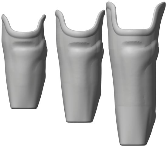
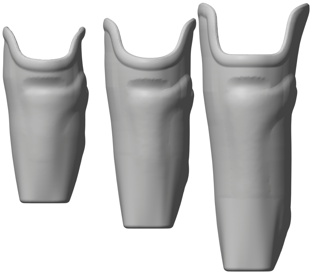
A prosthetist/orthotist designed 5 mm thick patellar-tendon-bearing (PTB) sockets using the three SSM-derived source geometries and a consistent procedure (Figure 3). For each socket, a mock residual limb was then constructed from its inner surface and extended proximally beyond the trimline. The opposing surfaces were designed to coincide within the socket, including at the distal end. This procedure established a common geometric fitting assumption across all nine cases, avoiding prescribed clearance or interference as additional variables in the comparison. For each socket, the same mock limb geometry was used for all three material representations.
Figure 3.
Prosthetic socket designs corresponding to the SSM-derived residual limb geometries at the 2.5th, 50th, and 97.5th percentiles of the PC1 score distribution, shown from left to right. All three sockets were designed by a prosthetist/orthotist using a consistent procedure, with a thickness of 5 mm.
2.3. Finite Element Model and Loading Conditions
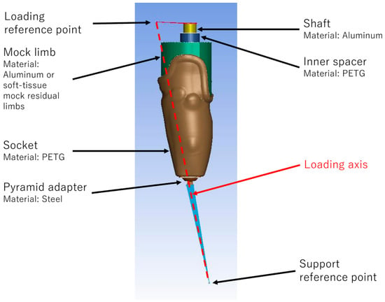
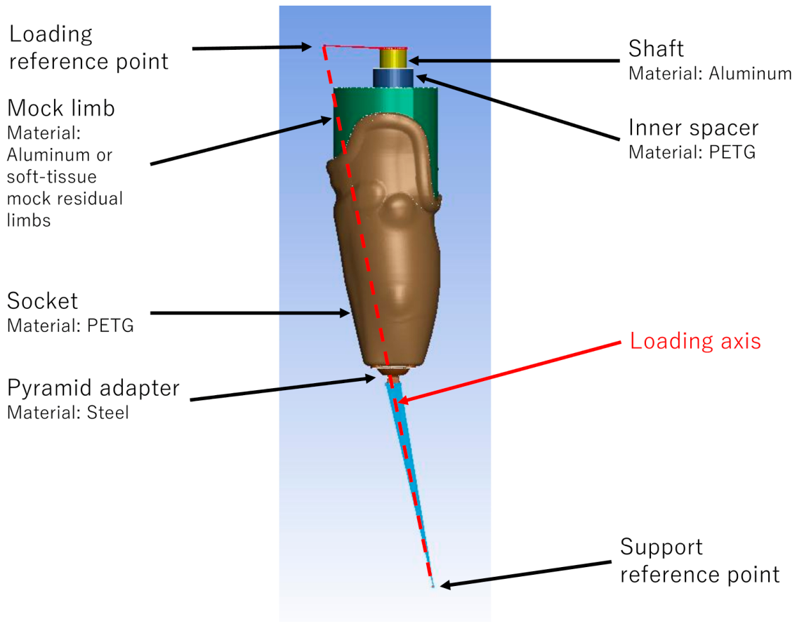
Finite element meshes of the three socket assemblies, including their matching mock limbs, were prepared in LS-PrePost 2025 R1 and solved with OpenRadioss (Windows 64-bit build dated 22 April 2025). The assembly comprised a glycol-modified polyethylene terephthalate (PETG) socket representing a 3D-printed design, mock limb, PETG inner spacer, aluminum shaft, and steel pyramid adapter (Figure 4; Table 1). Three homogeneous mock limb materials yielded nine geometry–material cases. Each material representation was assigned to every geometry using the same constitutive parameters across shapes. Material properties were therefore varied independently of PC1, rather than estimated from shape percentile or patient-specific tissue measurements. The muscle-inspired surrogate used first-order Ogden coefficients μ1 = 15.6 kPa and α1 = 21.4, reported for rat muscle and subsequently used in a human lower-limb muscle model [20,21]. The bulk soft-tissue surrogate used μ1 = 12 kPa and α1 = 14 from residual limb modelling [22], not an adipose-specific calibration. Both retained density 1000 kg/m3 and Poisson’s ratio 0.495; aluminum was the third representation. Neither surrogate resolved anatomical tissue layers or bone geometry. The compliant surrogates used nonlinear, isotropic hyperelastic behavior; no viscoelastic relaxation or fiber-direction dependence was prescribed.
Figure 4.
Finite element assembly and loading configuration. The socket and inner spacer were PETG, the shaft was aluminum, and the pyramid adapter was steel. The mock residual limb matched the socket inner surface by design, extended above the trimline, and was assigned aluminum, a muscle-inspired soft-tissue surrogate, or a bulk soft-tissue surrogate in separate simulations. The red dashed line connects the loading and support reference points and indicates the loading axis. A compressive force increased to 4480 N at 1.0 s, acting from the loading point toward the support point, based on ISO 10328 condition I at level P5. Material parameters are listed in Table 1. PETG, glycol-modified polyethylene terephthalate.
Table 1.
Component materials and parameters for the finite element model.
Table 2 summarizes dimensions of the SSM-derived source surfaces used for socket design and the corresponding sockets. Source-shape length (L) followed the longitudinal axis from MPT to the distal tip, including the lofted closure. Circumferences came from closed surface-intersection contours perpendicular to that axis at MPT and halfway to the tip. These source-shape dimensions describe the inputs to socket design, rather than the final mock limbs constructed from the socket inner surfaces. Socket length extended axially from MPT to the outer distal base, excluding adapter and shaft. These descriptors did not redefine the PCA origin.
Table 2.
Representative dimensions of the SSM source geometries and corresponding sockets.
Loading was based on ISO 10328 test loading condition I at level P5, with a prescribed peak force of 4480 N.
All nine cases used SI units (m, kg, s) and the same element formulations, loading and boundary conditions, and contact definitions. Socket, mock limb and adapter used four-node tetrahedra (ELFORM 10); shaft and spacer used hexahedra and degenerate wedges (ELFORM 1). Non-soft-tissue components were isotropic linear elastic, without failure criteria. Mock limb–socket contact used static and dynamic friction coefficients of 0.5; automatic surface-to-surface contact allowed frictional relative sliding and local separation as the contact state evolved. Thus, matching the initial surfaces did not impose a bonded interface. In contrast, tied interfaces were defined between shaft–spacer, spacer–mock limb, and adapter–socket bottom.
The shaft top and adapter base were coupled to loading and support reference nodes, respectively. Compression was applied along the initial line connecting these nodes, inclined by 15.45° from the global −Z axis. The prescribed load path ran from the shaft through the tied spacer and mock limb, across the frictional mock limb–socket interface, and through the socket to the supported adapter.
The loading node could translate only along the loading axis, whereas the support node was fixed in translation. Both nodes could rotate only about their respective local X axes.
The force amplitude followed a tabulated smooth ramp with 0.05 s sampling intervals, increasing from 0 N at 0 s through 2240 N at 0.5 s to 4480 N at 1.0 s, when the analysis ended.
2.4. Stress Evaluation at Reported Fracture Regions
Element-wise von Mises stresses were evaluated in ParaView 5.13.3 without nodal averaging. Regional maximum von Mises stresses at the final simulation time (1.0 s) were compared post hoc across all nine cases. The trimline region comprised the socket wall within a surface distance of 15 mm from the entire proximal rim. The distal attachment region comprised the flat socket-bottom surface at the adapter interface. Region definitions were based on the undeformed socket geometry and matched across materials within each geometry. Whole-socket maxima and their locations were retained as complementary outcomes. For peak-location classification, the inner-bottom region was defined as the inner socket surface extending 50 mm proximally from its most distal point, measured along the socket longitudinal axis. This height was selected to encompass the region of concentrated contact during loading transmitted through the mock residual limb. The analysis evaluated stresses associated with reported fracture sites, not failure mechanisms. No inferential statistical tests were performed.
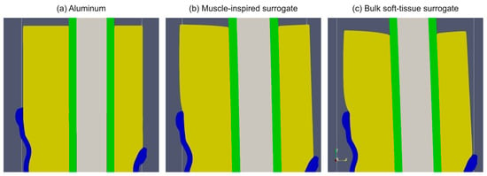
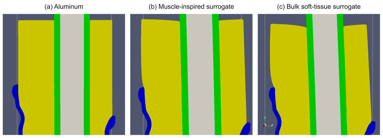
To supplement the stress comparison, trimline-region views of the 50th-percentile assembly were inspected qualitatively in ParaView for the three mock limb materials. These views illustrated relative settling and local deformation; displacement was not quantified.
Socket mesh sensitivity was examined for the PC1 50th-percentile geometry with the aluminum mock limb using four socket mesh resolutions (Coarse 1, Coarse 2, Baseline, and Fine). Only the socket was remeshed; the mock limb mesh, material properties, loading history, boundary conditions, and contact definitions were retained. The meshes were characterized by their tetrahedral element counts and mean unique edge lengths, calculated from the undeformed nodal coordinates with shared edges counted once. The distal-attachment maximum von Mises stress was compared at 1.0 s and 4480 N using the same regional definition and element-wise evaluation without nodal averaging. Baseline was used for the nine-case comparison.
Loading-duration sensitivity was evaluated for the 50th-percentile geometry with the aluminum mock limb because dynamic finite element responses can depend on loading rate [23]. The force-ramp time coordinates and analysis end time were scaled to reach 4480 N at 0.5, 1.0, or 2.0 s, while retaining the same normalized load history and all other model settings. The distal-attachment maximum von Mises stress was compared at the final time of each run using the same regional definition and element-wise evaluation without nodal averaging.
3. Results
3.1. Geometries Selected from the Statistical Shape Model
PC1 and PC2 explained 44.5% and 19.1% of coordinate variance, respectively; the first four components explained 82.4%, and 11 components were required to exceed 95%. The empirical 2.5th, 50th, and 97.5th percentiles corresponded to PC1 scores of −1.403, −0.142, and +2.549 standard deviations, respectively. Their sampled axial spans were 244.0, 303.8, and 431.4 mm. These spans cover the sampled scan region, exclude the distal closure added by the loft, and should not be interpreted as clinical residual limb lengths. Figure 2d shows the PC1-PC2 score distribution, and Figure 2e shows the completed surface at the 50th percentile of PC1.
The reconstructed mean matched the archived mean exactly, and the three representative point sets matched the archived text coordinates within numerical precision. Mean leave-one-out reconstruction error was 4.176 mm. After temporary closure of the proximal rim, the meshes were watertight with consistent face orientation and no detected intersections between nonadjacent triangles. Surface checks detected no gaps or steps at the junction between the lofted side surface and the distal closure, so the two formed a single continuous surface; the open-proximal triangulations approximate that surface.
3.2. Socket Stress Distributions
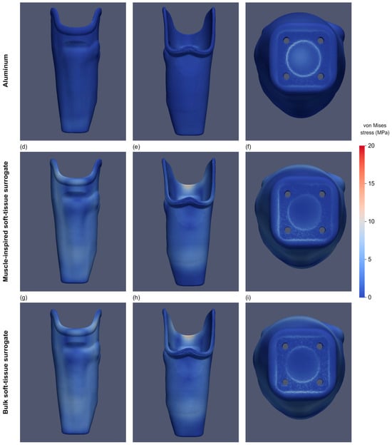
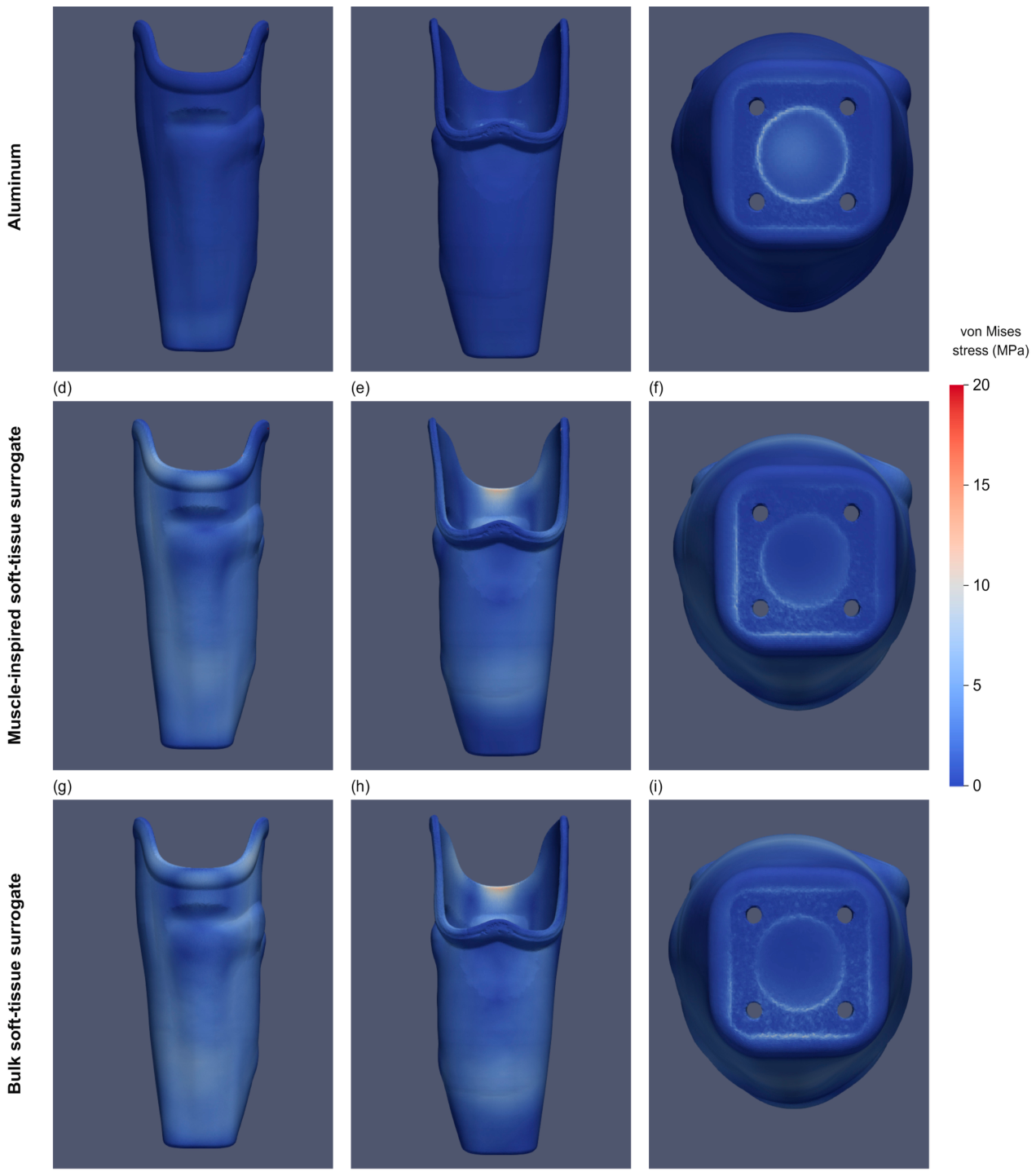
Peak locations differed by material in the 2.5th- and 50th-percentile geometries: at socket-bottom contact with the pyramid adapter for aluminum and at the anterior trimline for both soft-tissue surrogates. At the 97.5th percentile, all materials produced distal peaks: at pyramid-adapter contact for aluminum (4.9 MPa) and at the inner socket bottom for the muscle-inspired (5.0 MPa) and bulk (4.0 MPa) surrogates. Figure 5 shows Front, Back, and Bottom stress maps at the 50th percentile, with panels d–f and g–i corresponding to muscle-inspired and bulk surrogates, respectively.
Figure 5.
Socket von Mises stress distributions at 1.0 s for the socket assembly based on the 50th-percentile PC1 source geometry. Columns show Front, Back, and Bottom views. (a–c) Aluminum mock limb. (d–f) Muscle-inspired soft-tissue surrogate (μ1 = 15.6 kPa; α1 = 21.4). (g–i) Bulk soft-tissue surrogate (μ1 = 12 kPa; α1 = 14). All panels use a common color scale of 0–20 MPa. Table 3 distinguishes the two regional endpoints from the whole-socket reference maximum.
3.3. Comparison of Material Representations
Trimline stresses for aluminum, the muscle-inspired surrogate, and the bulk soft-tissue surrogate were 1.0, 16.0, and 19.7 MPa at the 2.5th percentile; 1.5, 12.4, and 14.1 MPa at the 50th; and 0.7, 3.9, and 3.9 MPa at the 97.5th (Table 3). Both surrogates exceeded aluminum in the trimline region in every geometry. At the distal attachment, both exceeded aluminum only at the 2.5th percentile; aluminum produced the highest value at the 50th and 97.5th percentiles.
Table 3.
Regional maximum von Mises stresses associated with reported fracture sites across nine geometry–material conditions.
Visual inspection of the 50th-percentile assembly showed material-dependent differences in mock limb settling relative to the socket trimline (Figure 6). The compliant surrogates exhibited local contour changes near the trimline compared with aluminum. These views provide a qualitative illustration of the deformation patterns accompanying the stress comparison.
Figure 6.
Representative views of mock limb deformation near the socket trimline for the 50th-percentile PC1 assembly. (a) Aluminum. (b) Muscle-inspired soft-tissue surrogate. (c) Bulk soft-tissue surrogate. Colors identify model components rather than stress magnitude. The images illustrate material-dependent settling and local deformation qualitatively.
3.4. Loading-Duration Comparison
For the 50th-percentile geometry with the aluminum mock limb, the distal-attachment maximum von Mises stresses at 4480 N were 12.8, 9.9, and 10.6 MPa for loading durations of 0.5, 1.0, and 2.0 s, respectively. Relative to the 1.0 s result, the 0.5 s value was higher by 2.9 MPa (29.3%), and the 2.0 s value was higher by 0.7 MPa (7.1%).
3.5. Socket Mesh Sensitivity
For the PC1 50th-percentile geometry with the aluminum mock limb, distal-attachment maximum von Mises stresses were 8.9, 8.9, 9.9, and 11.0 MPa for Coarse 1, Coarse 2, Baseline, and Fine, respectively (Table 4). Relative to Baseline, both coarser meshes differed by −10.1% and Fine by +11.1%.
Table 4.
Socket mesh sensitivity for the PC1 50th-percentile geometry with the aluminum mock limb.
4. Discussion
The results connect geometry selection and mock limb specification as two decisions in structural test design. Both compliant surrogates increased trimline stress relative to aluminum in all three geometries, whereas their effects at the distal attachment depended on geometry. Regional comparisons therefore help identify how a test configuration loads different socket regions across the selected shapes. This supports assessing patient-derived shape variation together with internal support conditions when developing a structural assessment framework.
4.1. Material Representation and Load Transfer
Material-dependent settling near the trimline (Figure 6) may contribute to differences in local load transfer. These qualitative views do not establish a quantitative relationship between settling and peak socket stress.
All nine cases used mock limbs designed to match the socket inner surfaces, with no distal clearance. The inner-bottom stress peaks in the 97.5th-percentile compliant mock limbs occurred under this common design condition. Material-dependent deformation may redistribute loading between the proximal socket wall and the inner bottom, with the distribution also influenced by the selected geometry. This interpretation remains a hypothesis because contact-pressure and deformation histories were not evaluated. The homogeneous mock limbs did not resolve anatomical bones or tissue layers, which also limits interpretation of the load-transfer mechanism. PC1 changes length, circumference, and contour together, so length cannot be isolated as the cause.
Friction, relative sliding, and local separation were therefore permitted despite the initially matching surfaces. Frictional traction and the evolving contact area can affect how the applied load is shared between the socket wall and distal regions. However, neither the friction coefficient nor the loading direction and tied fixture interfaces were varied. Their influence on the reported stresses was not quantified, and the material comparisons are conditional on this common loading and contact configuration [15].
The Ogden representations already included nonlinear elastic response, but the comparison of two parameter sets was not a systematic constitutive sensitivity analysis. Viscoelastic relaxation and anisotropy could change mock limb deformation and load transfer; their effects on trimline stress cannot be quantified from these cases. The loading-duration comparison used aluminum and does not test rate-dependent behavior of the compliant surrogates. The material findings therefore apply to the specified homogeneous constitutive representations.
The present stress locations are qualitatively consistent with part of this clinical-versus-bench pattern. The anterior trimline peaks in both soft-tissue representations at the 2.5th and 50th PC1 percentiles correspond broadly to the patellar-tendon region where van der Stelt et al. observed clinical fractures [13]. Their additional popliteal fractures were not reproduced as peak locations here. Conversely, the socket-bottom peaks at pyramid-adapter contact in all three aluminum cases correspond to the distal socket and attachment failures reported by Kim et al. [12]. The correspondence is regional rather than an exact match of crack initiation sites.
At the 97.5th percentile, both soft-tissue representations retained trimline stresses of 3.9 MPa despite their higher inner-bottom peaks. These studies do not isolate mock material as the cause of failure location. Kim et al. used condition II rather than the present ISO 10328 condition I loading, and the clinical study involved repeated use of different socket designs and materials. These spatial parallels support investigating internal support and load transfer [2], but do not demonstrate a shared fracture mechanism or validate predicted failure loads.
The shift in peak location is relevant to developing socket tests based on ISO 10328 loading. The AOPA Socket Guidance Workgroup identified incomplete specification of mock limb composition as a gap in adapting these tests to sockets [2]. The present results support considering complementary mock limb property sets: a single support condition should not be assumed to produce the most demanding loading at every socket region or for every geometry. Such a strategy could help include both distal and trimline regions in structural assessment. The property sets would need a justified load-transfer basis and experimental confirmation of the resulting regional response before use in qualification testing.
4.2. Patient-Derived Shape Sampling and the Design Envelope
Previous research has combined residual limb shape, soft-tissue properties, and socket design in population-based finite element analyses of interface pressure, shear, and tissue strain [14]. Steer et al. recommended comparative interpretation of residuum–socket finite element models [15], and our earlier work assessed registration quality, cross-sectional shape representation, and SSM evaluation metrics [19]. The present contribution is to connect statistical shape selection with the choice of internal support conditions for structural assessment at reported socket fracture regions. This provides an initial computational implementation of part of a broader assessment framework.
The added finding is that the material comparison depends on both the region and selected geometry. Both compliant representations increased trimline stress relative to aluminum in all three geometries, whereas distal attachment stresses showed no common direction of change across geometries. Whole-socket peaks shifted from the distal attachment to the anterior trimline at the 2.5th and 50th PC1 percentiles; at the 97.5th percentile they remained distal, with inner-bottom peaks for the compliant representations. A material comparison based on one geometry or a single whole-socket maximum can therefore miss differences between potential fracture regions.
Selecting empirical PC1 percentiles linked the test geometries to shape variation observed in the patient dataset. A mechanically influential parameter may identify a demanding configuration without establishing how well that configuration represents observed patient geometry or its combinations of features. Conversely, a frequently observed shape is not necessarily mechanically critical. Patient-derived shape sampling and mechanical sensitivity therefore provide complementary information for defining and evaluating a design envelope. The present selection addressed observed shape variation, without optimizing for peak stress or claiming to identify worst-case strength conditions.
The empirical 2.5th, 50th, and 97.5th PC1 percentiles provided a reproducible sampling rule along the dominant observed mode, with other modes fixed. Material comparisons within each geometry retained the same socket and matching mock limb geometry. This controlled the prescribed geometric fit, while comparisons between geometries included the effects of socket design and the resulting mock limb shape. These assemblies represent structural test surrogates under a common fitting assumption. Geometric matching does not reproduce the press-fit and donning-induced tissue stresses that can affect load transfer in clinical use [15]. Intermediate PC1 geometries were not simulated. The observed direction of the trimline material comparison was shared by the three sampled shapes, but its persistence between those shapes and the location of any change in the dominant stress region remain untested.
The present SSM represents liner-covered surfaces from one geographic cohort. The 67 archived records may not capture the full range of residual limb lengths, contours, and other anatomical characteristics within the intended population. Representativeness across other patient populations was not established, so the selected geometries should be interpreted as samples of variation within this dataset. Its selected PC1 percentiles describe a limited sample of the shape component of a design envelope; they are not validated design boundaries or established worst cases. Three PC1 shapes do not establish coverage of 95% of population geometries. Higher-order PCs and their combinations may generate clinically relevant contours absent from the selected shapes. Fixing these scores at zero excluded their contribution to the comparison and did not establish that their mechanical influence was negligible. PC1 combines length, circumference, and contour, preventing attribution to individual features. Generalization requires assessment of cohort representativeness, additional shape modes, and operator variability; a variance threshold alone cannot establish mode stability or sample adequacy [24].
4.3. Stress Assessment at Reported Fracture Regions
The analysis describes predicted stresses at regions associated with reported fractures, not failure modes. Printed polymers may exhibit orientation-dependent mechanical behavior, and experimental socket research has specifically examined printing orientation [4]. A scalar von Mises stress peak alone cannot establish interlayer separation, tensile cracking, or a clinically relevant failure load. Extending this work to predicted damage would require a justified constitutive and failure model with appropriate material data.
The primary aim was to compare how geometry and mock limb material influence regional socket stress distributions. The four-mesh assessment quantified sensitivity of the distal-attachment maximum in the PC1 50th-percentile aluminum condition. Absolute peak stresses should be interpreted in light of this mesh sensitivity and are not treated as validated failure stresses. Because only this condition and region were assessed, the mesh sensitivity of the geometry–material comparisons and of trimline peaks remains unverified.
These regional rankings do not establish a generally applicable worst-case socket. Wall thickness, trimline design, material and manufacturing choices, interface conditions, and loading direction extend beyond the shape variation sampled here. Evaluating a broader design envelope would require defining their permitted ranges and assessing whether the regional responses persist across the relevant combinations.
Loading-duration effects have also been examined in biomechanical finite element studies. Naghibi Beidokhti et al. compared knee-joint responses at loading durations of 0.02, 0.1, and 1.0 s, representing different gait speeds; the slow-loading results approached the quasi-static response [23]. In the present socket model, shortening the ramp from 1.0 to 0.5 s changed the distal-attachment maximum by 29.3%, whereas extending it to 2.0 s changed the maximum by 7.1%. The greater sensitivity to shortening the ramp supports retaining 1.0 s as a practical baseline for the main comparisons. The material and geometry effects reported here are interpreted within this common 1.0 s loading protocol. The additional duration comparison characterizes sensitivity for the representative 50th-percentile aluminum case.
4.4. Limitations and Future Directions
Because the 20 sections were positioned by relative scan height, differences in scan coverage could contribute to the fitted variation, and corresponding sections need not lie at equivalent anatomical levels. This representation does not impose a common MPT-referenced proximal boundary. The distal closure produced by the loft is a reproducible geometric construction, not a reconstruction of unobserved anatomy. The effects of section spacing, loft surface generation, and distal closure propagate through socket design and subsequent mock limb construction; their influence on the resulting contact and local stress should be assessed in future comparisons.
No physical validation is included, limiting interpretation of absolute stress values and precluding conclusions about clinical safety or experimentally verified structural performance. Patient comfort, protection of surrounding tissues, and long-term clinical outcomes were not evaluated. Whether the predicted material-dependent redistribution of socket stress occurs in physical sockets remains to be tested. External experimental evidence may help assess plausibility, but agreement with unrelated published observations would not validate this model. The present findings identify factors for further computational assessment and do not replace mechanical qualification testing.
Future experimental validation should determine whether the predicted material-dependent regional stress redistribution occurs in physical sockets. This should begin with bench testing of sockets and mock limbs with geometries, material properties, and loading conditions matched to the computational models. After independently characterizing the materials, force-displacement measurements and surface strains at the anterior trimline and distal attachment could be compared with the corresponding model outputs at the same load levels. Repeated measurements would allow discrepancies to be assessed against experimental variability. Interface-pressure measurements could provide complementary evidence on load transfer. These comparisons would test both the regional response and its change with mock limb material, rather than infer validation from agreement in peak location alone.
Broader assessment should include independent patient cohorts with a wider range of residual limb characteristics, additional shape modes, and relevant loading and socket configurations. This would help determine whether the observed regional material comparisons persist beyond the nine cases studied here. Translation to patient care would also require evaluation of clinical outcomes.
5. Conclusions
This study provides an initial computational demonstration of a population-informed framework for structural assessment of 3D-printed prosthetic sockets. A 67-record SSM supported reproducible shape selection, and comparisons under loading based on ISO 10328 showed that mock limb material affected regional stress magnitude and peak location. Aluminum produced distal attachment peaks in all geometries, while compliant surrogates produced anterior trimline peaks in the 2.5th- and 50th-percentile geometries and inner-bottom peaks in the 97.5th-percentile geometry. These findings support combining patient-derived shape sampling with complementary mock limb support conditions when developing tests for relevant socket regions. The sampled shapes represent observed variation, not worst-case strength conditions. The observed material comparisons are conditional on the three geometries and single loading configuration examined. Broader design-envelope assessment and physical validation are needed before the approach can support structural product assurance.
Author Contributions
S.K. was the principal investigator and contributed to the analysis, data collection, and summarization. S.Y. contributed to methodological validation, manuscript revision, and approval of the final version. All authors have read and agreed to the published version of the manuscript.
Funding
This research received no external funding.
Institutional Review Board Statement
This study was conducted in accordance with the Declaration of Helsinki and approved by the Institutional Ethics Committee of Shibaura Institute of Technology (approval code: 25-016, date of approval: 7 May 2025).
Informed Consent Statement
Informed consent was obtained from all subjects involved in this study. Written informed consent has been obtained from the patients to publish this paper.
Data Availability Statement
The data is available from the corresponding author upon reasonable request, subject to ethical and institutional restrictions.
Acknowledgments
During the preparation of this manuscript and study, the authors used ChatGPT (GPT-6-astra; OpenAI) and Claude Code (Claude Opus 5.5; Anthropic) for language and grammar improvement. The authors have reviewed and edited the output and take full responsibility for the content of this publication.
Conflicts of Interest
One author, Shinichiro Kon, was employed by the company Instalimb, Inc. The remaining authors declare that the research was conducted in the absence of any commercial or financial relationships that could be construed as potential conflicts of interest.
References
- Gariboldi, F.; Pasquarelli, D.; Cutti, A.G. Structural testing of lower-limb prosthetic sockets: A systematic review. Med. Eng. Phys. 2022, 99, 103742. [Google Scholar] [CrossRef] [Scilit] [PubMed]
- Gariboldi, F.; Cutti, A.G.; Fatone, S.; Nickel, E.; Dickinson, A.; Steer, J.; Erenstone, J.; Zahedi, S.; AOPA Socket Guidance Workgroup. Mechanical testing of transtibial prosthetic sockets: A discussion paper from the American Orthotic and Prosthetic Association Socket Guidance Workgroup. Prosthet. Orthot. Int. 2023, 47, 3–12. [Google Scholar] [CrossRef] [Scilit] [PubMed]
- Kim, S.; Yalla, S.; Shetty, S.; Rosenblatt, N.J. 3D printed transtibial prosthetic sockets: A systematic review. PLoS ONE 2022, 17, e0275161. [Google Scholar] [CrossRef] [Scilit] [PubMed]
- Che Manan, A.F.; Abd Latif, M.J.; Narasamman, M.; Musa, M.; Rahman, M.N.A.; Lim, G.D.; Rajaandra, P. Effect of printing orientation on structural strength of 3D-printed polylactic acid prosthetic socket using fused deposition modeling. Prosthet. Orthot. Int. 2026, 50, 110–114. [Google Scholar] [CrossRef] [Scilit] [PubMed]
- Lee, D.R.C.; Yang, X.; Riccio-Ackerman, F.; Alemón, B.; Ballesteros-Escamilla, M.; Solav, D.; Lipsitz, S.R.; Moerman, K.M.; Meyer, C.I.; Jaeger, A.M.; et al. A clinical comparison of a digital versus conventional design methodology for transtibial prosthetic interfaces. Sci. Rep. 2024, 14, 25833. [Google Scholar] [CrossRef] [Scilit] [PubMed]
- van der Stelt, M.; Berends, B.; Papenburg, M.; Langenhuyzen, T.; Maal, T.; Brouwers, L.; de Jong, G.; Leijendekkers, R. Evaluating the effectiveness of transtibial prosthetic socket shape design using artificial intelligence: A clinical comparison with traditional plaster cast socket designs. Arch. Phys. Med. Rehabil. 2025, 106, 239–246. [Google Scholar] [CrossRef] [Scilit] [PubMed]
- Mbithi, F.; Donovan-Hall, M.; Bramley, J.; Steer, J.; Rossides, C.; Worsley, P.; Ostler, C.; Metcalf, C.; Hannett, D.; Ward, C.; et al. Evidence-generated sockets for transtibial prosthetic limbs compared with conventional computer-aided designs: A multiple-methods study from the patient’s perspective. JMIR Rehabil. Assist. Technol. 2025, 12, e69962. [Google Scholar] [CrossRef] [Scilit] [PubMed]
- Silver-Thorn, M.B.; Childress, D.S. Parametric analysis using the finite element method to investigate prosthetic interface stresses for persons with trans-tibial amputation. J. Rehabil. Res. Dev. 1996, 33, 227–238. [Google Scholar] [PubMed]
- Baharuddin, M.H.; Abdullah, N.N.A.A.; Kori, M.I.; Gan, H.-S.; Abdul Kadir, M.R.; Ramlee, M.H. Prosthetic leg socket design: New insight on different tibia length and distal bevelled angle using finite element analysis. Injury 2026, 57, 113472. [Google Scholar] [CrossRef] [Scilit] [PubMed]
- Sunderland, F.; Sobey, A.; Bramley, J.; Steer, J.; Al-Dirini, R.; Metcalf, C.; Toderita, D.; Bull, A.; Ding, Z.; Henson, D.; et al. OpenLimbTT, a transtibial residual limb shape model for prosthetics simulation and design: Creating a statistical anatomic model using sparse data. Data-Centric Eng. 2025, 6, e39. [Google Scholar] [CrossRef] [Scilit]
- Shahapurkar, G.S.; Plesec, V.; Harih, G.; Bapat, G.M. Investigating materials composition and shape morphology of an anthropomorphic mock residual limb for prosthetic socket testing. In Advances in Digital Human Modeling III; Harih, G., Plesec, V., Eds.; Springer: Cham, Switzerland, 2026; pp. 189–203. [Google Scholar] [CrossRef] [Scilit]
- Kim, S.; Yalla, S.V.; Shetty, S.; Rosenblatt, N.J. Structural integrity of custom-designed additive manufactured prosthetic sockets compared to traditional sockets. Results Mater. 2024, 21, 100549. [Google Scholar] [CrossRef] [Scilit]
- van der Stelt, M.; Stenveld, F.; Bitter, T.; Maal, T.J.J.; Janssen, D. Design evaluation of FFF-printed transtibial prosthetic sockets using follow-up and finite element analysis. Prosthesis 2022, 4, 589–599. [Google Scholar] [CrossRef] [Scilit]
- Steer, J.W.; Worsley, P.R.; Browne, M.; Dickinson, A.S. Predictive prosthetic socket design: Part 1—Population-based evaluation of transtibial prosthetic sockets by FEA-driven surrogate modelling. Biomech. Model. Mechanobiol. 2020, 19, 1331–1346. [Google Scholar] [CrossRef] [Scilit] [PubMed]
- Steer, J.W.; Worsley, P.R.; Browne, M.; Dickinson, A. Key considerations for finite element modelling of the residuum–prosthetic socket interface. Prosthet. Orthot. Int. 2021, 45, 138–146. [Google Scholar] [CrossRef] [Scilit] [PubMed]
- Rajashekar, K.K.; Regalla, S.P.; Suresh, K.; Shrivastava, P.N. Fatigue behavior and durability assessment of additively manufactured below-knee prosthetic sockets using FEA and experimental testing. Fatigue Fract. Eng. Mater. Struct. 2026, 49, 848–859. [Google Scholar] [CrossRef] [Scilit]
- Dickinson, A.; Diment, L.; Morris, R.; Pearson, E.; Hannett, D.; Steer, J. Characterising residual limb morphology and prosthetic socket design based on expert clinician practice. Prosthesis 2021, 3, 280–299. [Google Scholar] [CrossRef] [Scilit]
- Nagarajan, Y.R.; Farukh, F.; Silberschmidt, V.V.; Kandan, K.; Singh, A.K.; Mukul, P. Shape analysis of prosthetic socket rectification procedure for transtibial amputees. Prosthesis 2024, 6, 157–174. [Google Scholar] [CrossRef] [Scilit]
- Kon, S.; Agarie, Y.; Suda, H.; Otsuka, H.; Ohnishi, K.; Hanahusa, A.; Takagi, M.; Yamamoto, S. Registration quality and the limits of statistical shape modeling evaluation in transtibial residual limb modeling: A cross-sectional shape representation framework. Prosthesis 2026, 8, 65. [Google Scholar] [CrossRef] [Scilit]
- Bosboom, E.M.H.; Hesselink, M.K.C.; Oomens, C.W.J.; Bouten, C.V.C.; Drost, M.R.; Baaijens, F.P.T. Passive transverse mechanical properties of skeletal muscle under in vivo compression. J. Biomech. 2001, 34, 1365–1368. [Google Scholar] [CrossRef] [Scilit] [PubMed]
- Marinopoulos, T.; Zani, L.; Li, S.; Silberschmidt, V.V. Modelling indentation of human lower-limb soft tissue: Simulation parameters and their effects. Contin. Mech. Thermodyn. 2023, 35, 939–955. [Google Scholar] [CrossRef] [Scilit]
- Plesec, V.; Harih, G. Development of a generic numerical transtibial model for limb-prosthesis system evaluation. Appl. Sci. 2023, 13, 2339. [Google Scholar] [CrossRef] [Scilit]
- Naghibi Beidokhti, H.; Janssen, D.; Khoshgoftar, M.; Sprengers, A.; Perdahcioglu, E.S.; Van den Boogaard, T.; Verdonschot, N. A comparison between dynamic implicit and explicit finite element simulations of the native knee joint. Med. Eng. Phys. 2016, 38, 1123–1130. [Google Scholar] [CrossRef] [Scilit] [PubMed]
- Mei, L.; Figl, M.; Rueckert, D.; Darzi, A.; Edwards, P. Sample sufficiency and number of modes to retain in statistical shape modelling. In Medical Image Computing and Computer-Assisted Intervention—MICCAI 2008; Springer: Berlin/Heidelberg, Germany, 2008; pp. 425–433. [Google Scholar] [CrossRef] [Scilit] [PubMed]

Disclaimer/Publisher’s Note: The statements, opinions and data contained in all publications are solely those of the individual author(s) and contributor(s) and not of MDPI and/or the editor(s). MDPI and/or the editor(s) disclaim responsibility for any injury to people or property resulting from any ideas, methods, instructions or products referred to in the content. |
© 2026 by the authors. Licensee MDPI, Basel, Switzerland. This article is an open access article distributed under the terms and conditions of the Creative Commons Attribution (CC BY) license.