


Abstract
This study proposes a high-frequency Pulse Amplitude-Modulation Temporal-Interference (PAM-TI) current stimulation device, which utilizes two sets of Amplitude-modulated transcranial alternating current stimulation (AM-tACS): one AM frequency at f0 (where f0 = 2 kHz) (source 1) and the other AM frequency at f1 = f0 + f (where f1 = 2.01 kHz) (source 2), to generate a f (where f = 10 Hz) envelope modulated at a fc (where fc = 100 kHz) high carrier frequency. The high carrier frequency reduces body impedance and conserves more stimulation power, allowing it to penetrate the skin and reach the subcutaneous region. The proposed PAM-TI technique elevates the two current sources to a 100 kHz carrier frequency. Instead of the challenges associated with generating high-frequency stimulation currents using an MCU and DAC, the proposed PAM-TI stimulation device achieves this by simply utilizing a pair of complementary pulse-width modulations (PWMs). The push–pull technique is employed to balance the charging currents between the anode and cathode, synchronizing the current timing of Source 1 and Source 2 under the fc modulation condition. To minimize signal attenuation, the PAM circuit is integrated directly into the electrode, ensuring the high-frequency signal is generated close to the body and preventing degradation from long wires. Additionally, a dry pin-type spring-loaded electrode is used to reduce interference caused by hair when placed on the head. The device’s validity and current directionality were verified using a scalp tissue-mimicking phantom composed of agar and saline.
1. Introduction
At present, deep brain stimulation (DBS) is dominated by invasive brain stimulation technology, which is mainly suitable for brain diseases such as Parkinson’s disease [1], Alzheimer’s disease [2], and epilepsy [3]. Although DBS is helpful for some brain diseases, it can also cause some side effects, such as cognitive impairment, confusion, infection and bleeding during surgery, and risk of complications [4].
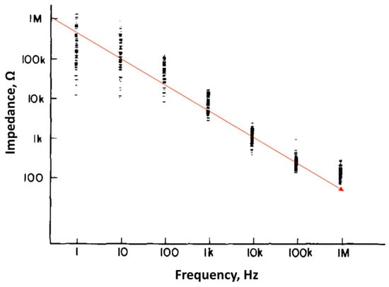
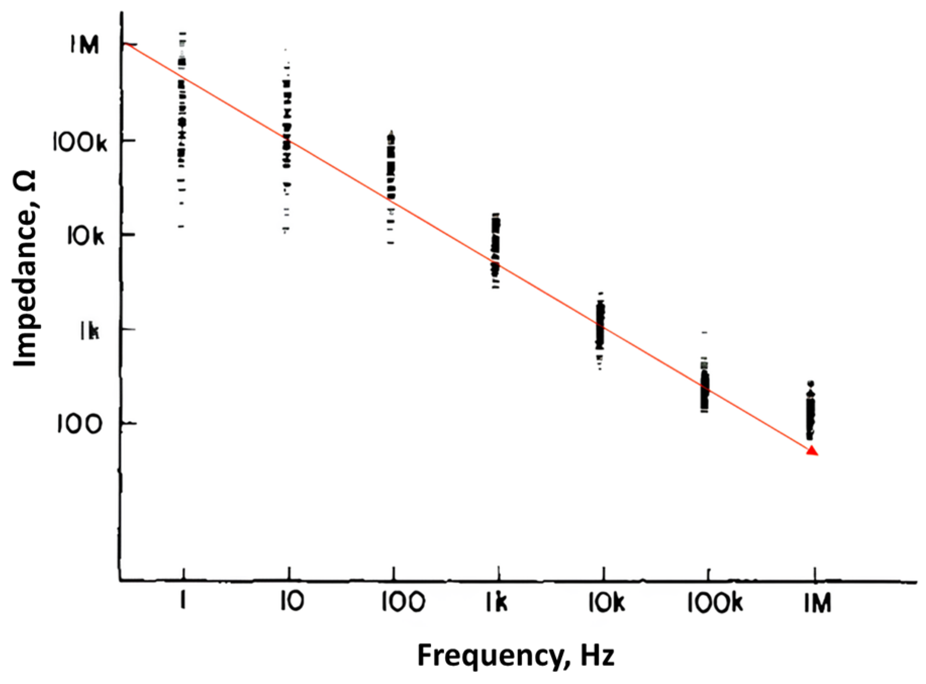
Non-invasive transcranial direct current stimulation (tDCS), transcranial alternating current stimulation (tACS) and transcranial magnetic stimulation (TMS) technologies can still only stimulate superficial areas of the brain. In order to achieve the goal of non-invasive deep brain stimulation, Grossman et al. (2017) [5] proposed temporal-interference electrical stimulation (TI). TI uses two or more channels to stimulate high-frequency tACS sinusoidal currents of different frequencies (such as 2 kHz and 2.01 kHz) to reach deeper brain tissues. The electric fields generated by the currents of each channel will meet and interfere with each other in the brain. The interference is an electric field envelope that oscillates at a frequency difference (10 Hz) between the two, and this modulated electric field is used to stimulate deep brain tissue. Since high-frequency current can directly pass through cells and intercellular substance, this high-frequency carrier current can reach deep brain areas (such as thalamus and hippocampus) without damaging the neurons on the conduction path [6,7]. However, most of the current research on TI electrical stimulation waveforms uses 2 kHz and 2.01 kHz for interference, where the bioimpedance is still a few kilohms, resulting in the amplifier being unable to operate at low voltage. According to previous studies [8,9], higher stimulation frequencies can reduce biological impedance, meaning that at the same stimulation current intensity, stimulation signals with higher frequencies can achieve the desired effect with a lower output voltage. The reduction in output voltage not only enhances the safety of the system but also reduces the supply voltage requirements, thereby decreasing the power consumption and heat dissipation of the output operational amplifier (OPA), making it more suitable for wearable system applications. For example, a higher frequency input of 100 kHz can reduce the bioimpedance to about 100 Ω, conserving more stimulation energy to penetrate through the skin surface. As shown in Figure 1, the impedance decreasing trend plot flattens out after 100 kHz.
Figure 1.
Bioimpedance versus frequency [9].
This study considered the advantages of AM-tACS and high-frequency carriers. We propose PAM-TI to modulate the f0 (where f0 = 2 kHz) and f1 = f0 + f (where f1 = 2.01 kHz) AM signals using a high carrier fc (where fc = 100 kHz) frequency. By modulating the f0 and f1 frequency waveforms with the fc frequency carrier, the interfered electrical stimulation at f frequency can be modulated at a high fc frequency and transmitted. This technique avoids the need for traditional high-frequency signal generators that require expensive high-clock MCUs and fast DACs, as seen in previous studies where the TI device implemented used an external DAC [10,11]. This study, however, does not rely on an external DAC. The study adopts a complementary PWM and digital switch architecture to modulate low-frequency f0 and f1 signals with an fc frequency carrier. As shown in Table 1, standard STM32 series microprocessors and DACs cannot output 100 kHz signals, and their minimum adjustable resolution does not meet the requirement of 10 Hz resolution. To address this issue, the proposed architecture does not directly generate two waveforms with a 10 Hz frequency difference at a high modulation frequency. Instead, it generates basic 2 kHz and 2.01 kHz waveforms and then uses PWM technology to produce PAM waveforms. This approach makes the PAM-TI technique more flexible, allowing any low-frequency AM-tACS signal to be elevated to a high-frequency carrier for transmission. Ultimately, we propose a high-frequency PAM-TI stimulation system. Compared to the traditional TI stimulation frequency of 2 kHz, PAM-TI can achieve stimulation frequencies of up to 100 kHz, significantly enhancing the system’s frequency range and application potential. In terms of efficiency and safety, PAM-TI effectively reduces the operating voltage of the system due to the lower output impedance, which not only improves the system’s safety but also reduces power consumption, thereby enhancing overall energy efficiency. This makes it more suitable for prolonged use and wearable applications. In terms of cost, increasing the frequency of traditional TI systems is constrained by the operating frequency of embedded systems, leading to a significant rise in system costs. In contrast, PAM-TI utilizes PWM signals and peripheral circuits for Pulse Amplitude Modulation (PAM), enabling higher-frequency stimulation signals without significantly increasing hardware costs, thus overcoming the technical and cost limitations of traditional TI systems at high-frequency stimulation.
Table 1.
PWM frequencies and resolutions of the STM32 series.
Past studies of electrical stimulation waveforms reported that the usage of biphasic waveforms is an essential safety issue to achieve charge balance during stimulation. It is a safety requirement to minimize tissue damage that is caused by unbalanced charge injection at the tissue–electrode interface [12,13]. This is why the PAM-TI technique proposed in this study employs complementary PWMs to maximize the phase difference between the two current sources in the TI system. Additionally, each current source is paired with a push–pull circuit design to draw current from the anode to the cathode within each source, preventing interference between the two current sources.
In terms of current source circuit design, past research usually used transformers to isolate the signals between distinct electrical stimulation channels [11,14]. However, transformers are bulky and heavy, making them challenging to integrate into wearable devices. In addition, transformers generate annoying noise, which can disturb users during sleep or rest. The current source in this study adopted the improved Howland circuit, in which the load end is isolated through an Operational Amplifier (OPA) buffer circuit and the feedback current was minimized to improve accuracy [15]. The electrical stimulation device designed in our work did not use a transformer for load-end isolation, making it lighter and more suitable for integration into wearable devices.
2. Materials and Methods
2.1. Electrode-Integrated PAM Circuit and Complementary PWM Control Board
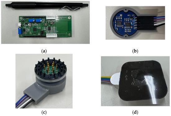
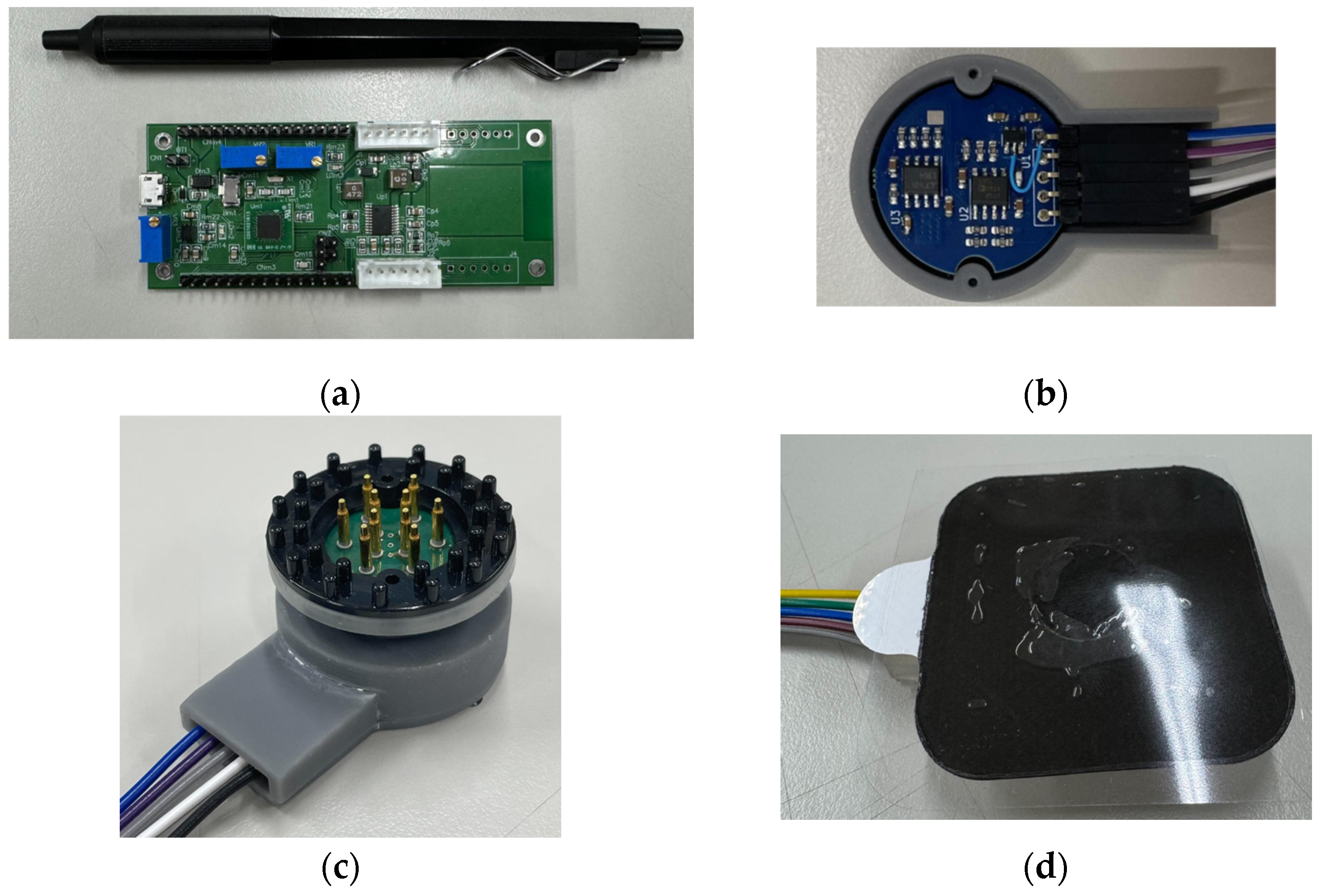
This study aims to modulate two sets of AM-TACS waves at a high carrier frequency. Since high-frequency analog signals may experience significant attenuation over long-distance transmission [16,17], the PAM output should be positioned close to the human body to avoid the attenuation of high-frequency currents. Therefore, this study integrates the PAM circuit into the electrode to minimize the distance between the generation of the high-frequency PAM signal and the stimulation site on the body, effectively preventing the attenuation of high-frequency analog signals in long wires. The electrode-integrated PAM (EIP) circuit receives PWM signals and power supply from the main control board. The main control board includes a complementary PWM generation circuit and a microprocessor with a DAC to produce low-frequency AM-TACS. The low-frequency AM-TACS and complementary PWM signals are transmitted from the main control board, as shown in Figure 2a to the electrode-integrated PAM (EIP electrode), as shown in Figure 2b. Within the EIP electrode, the PAM circuit modulates the AM-TACS signal to a high carrier frequency for subsequent use in temporal-interference (TI) current stimulation.
Figure 2.
(a) Integrated power supply main control board. (b) Electrode-integrated PAM circuit. (c) EIP circuit with dry pin-type spring-loaded electrode. (d) EIP circuit with wet electrode.
The EIP circuit designed in this paper offers high compatibility and can be used with either dry or wet electrodes, which can be selected according to the specific application needs, as shown in Figure 2c,d. Previous studies [18,19] have indicated that both dry and wet electrodes can establish effective electrical contact on the skin. Although dry electrodes result in higher contact impedance, they are generally preferred by users since they do not require conductive gels, highlighting their potential for practical applications. In the context of this paper, the PAM-TI stimulation frequency is much higher than that of traditional TI, which further mitigates the impact of higher contact impedance in dry electrodes, ensuring the stability of the stimulation signal and the applicability of the system.
2.2. Pulse-Amplitude Modulation Temporal Interference (PAM-TI)
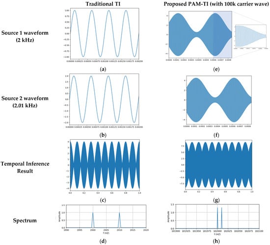
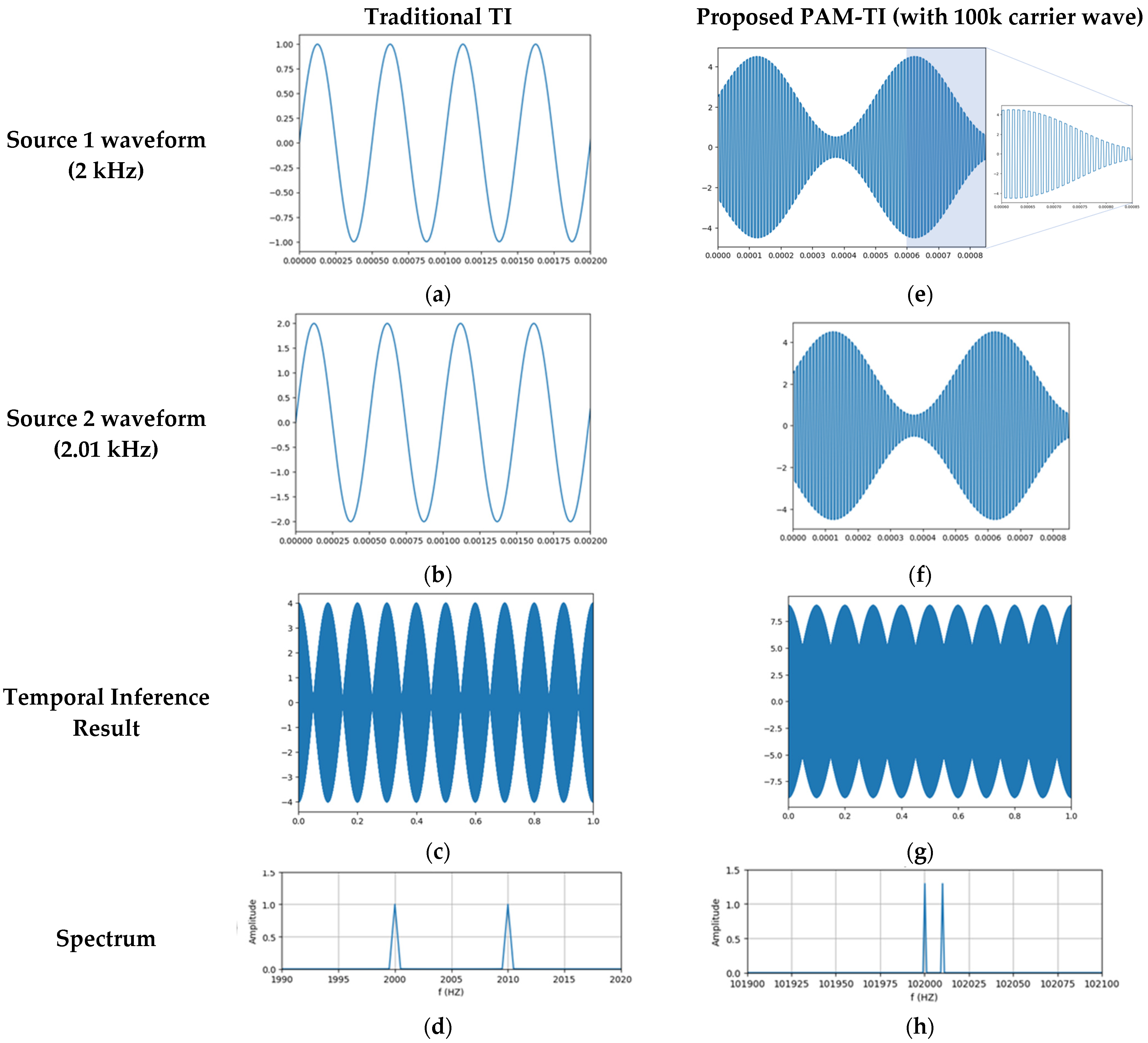
This paper designs a high-frequency PAM-TI waveform, which uses an fc (where fc = 100 kHz) high-frequency carrier to pulse amplitude modulate the f0 (where f0 = 2 kHz) and f1 = f0 + f (where f1 = 2.01 kHz) sine waves in the traditional TI waveform. Figure 3a shows the traditional TI of a 2 kHz sine wave, which is transformed into Figure 3e using PAM, where the amplitudes of the f0 sine wave are modulated by the fc carrier. Figure 3b shows the traditional TI of a 2.01 kHz sine wave, which is transformed into Figure 3f using PAM, where the amplitudes of the f1 sine wave are modulated by the fc carrier. Figure 3c shows the 10 Hz envelope waveform produced by the interference between the 2 kHz and 2.01 kHz waves in the traditional TI. Figure 3g shows the f envelope waveform produced by the interference of f0 with the fc PAM and f1 with the fc PAM in the PAM-TI. By comparing Figure 3d and 3h, we can see that the waveform proposed in this paper can shift the 2 kHz and 2.01 kHz components to the higher frequency side of f0 + fc and f1 + fc through the fc PAM carrier.
Figure 3.
(a) The sine wave with frequency 2 kHz; (b) The sine wave with frequency 2.01 kHz; (c) The TI wave consists of the envelope formed by the superposition of TI Source1 and TI Source2; (d) The spectrum of conventional TI; (e) The f0 sine wave with fc PAM; (f) The f1 sine wave with fc PAM; (g) The PAM-TI wave consists of the envelope formed by the superposition of PAM-TI Source1 and PAM-TI Source2; (h) The spectrum of PAM-TI.
2.3. Circuit Design and Simulation
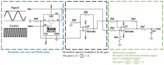
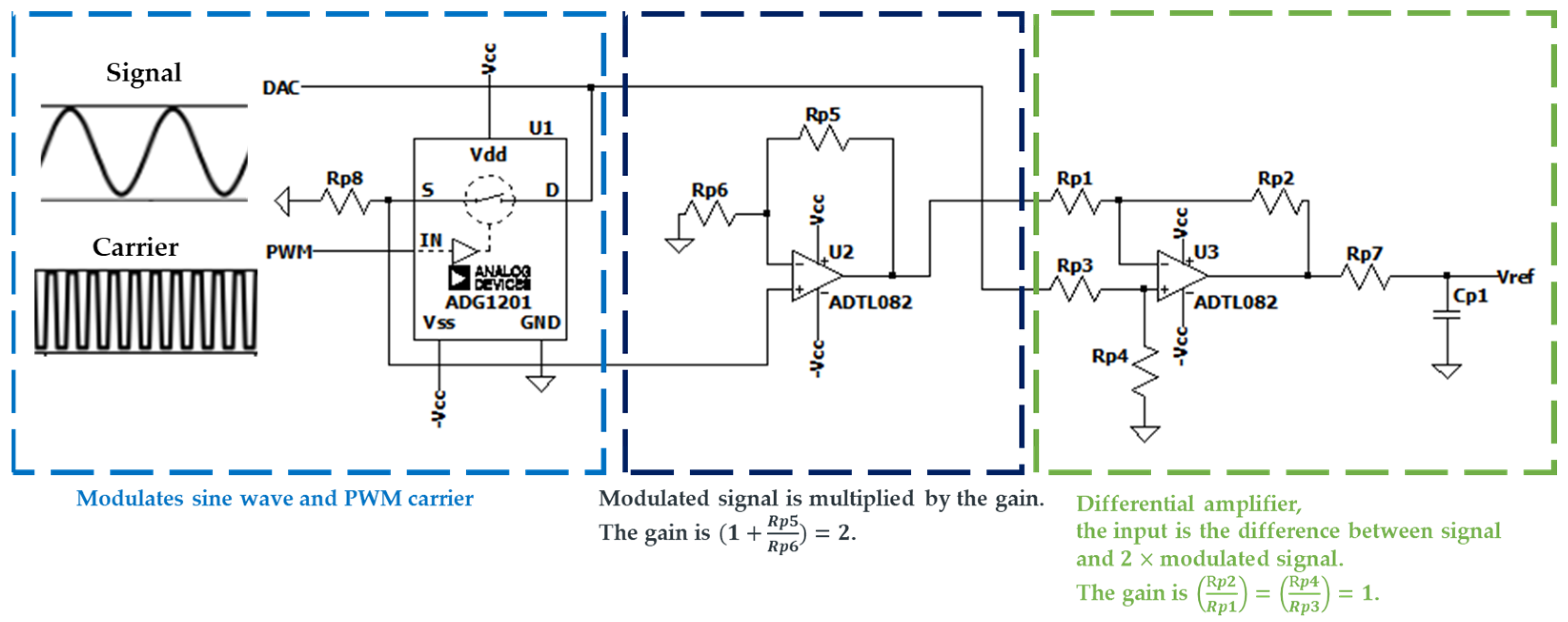
This section will show the PAM-TI current source generator circuit design and related formula derivation. The following circuit design is drawn and waveform output by LTspice circuit simulation software Version 24.1.1. Figure 4 shows how to generate PAM-TI Source. First, the signal is a sine wave generated by the DAC of the MCU, and the carrier is a square wave generated by the PMW of the MCU. The circuit uses switches to modulate the sine wave and the PWM carrier, and then multiplies the modulated signal by the gain of 2. The final output of the differential amplifier with the gain of 1 (Vref) is the difference between the signal and the multiplied modulated signal.
Figure 4.
PAM-TI Source waveform generator circuit.
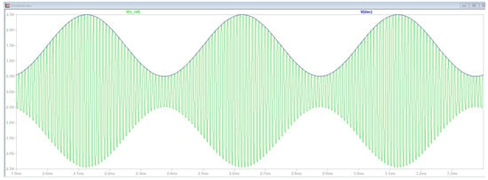
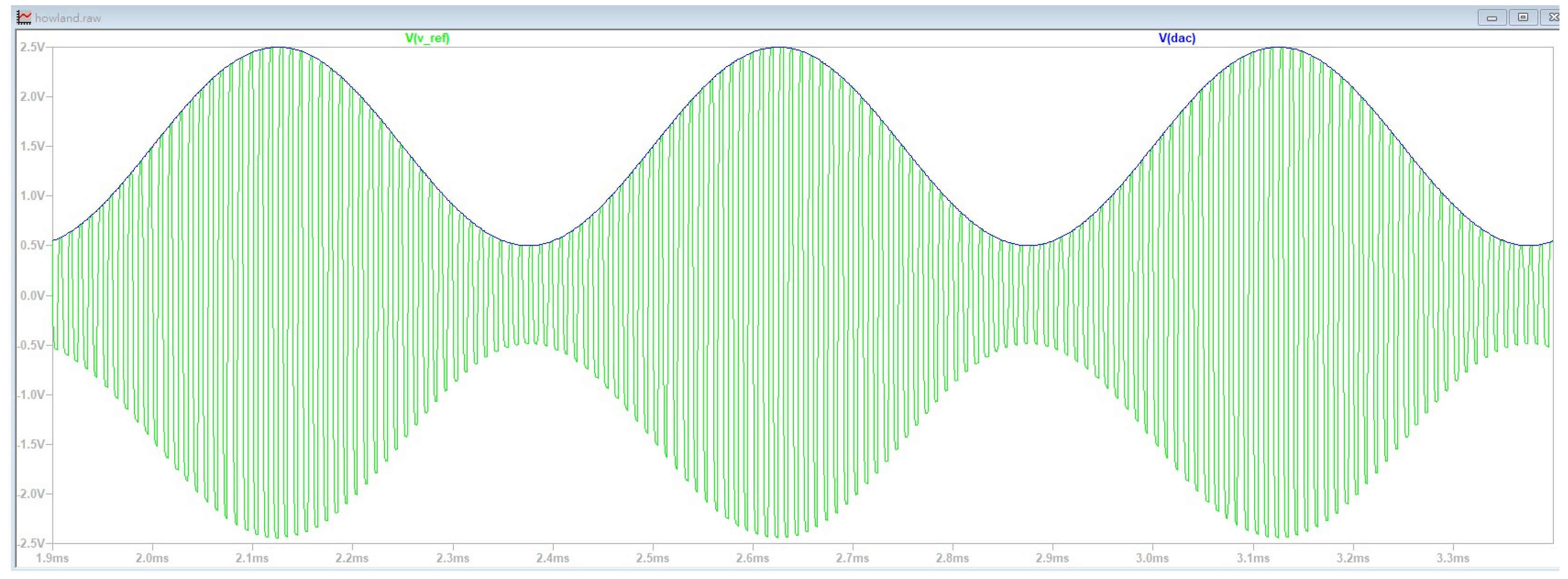
Figure 5 shows that the green line is the output (Vref) of the PAM-TI Source waveform generator circuit. The blue line is the sine wave generated by the DAC of MCU. Previous studies have shown that modulated waveforms can be transmitted to deep brain regions with less energy [20].
Figure 5.
The output (Vref) of PAM-TI Source waveform generator circuit.
The formula derivation is as follows (1)–(4):
sample period determined by PWM
sample value of m(t) obtained at is generated by DAC
Rectangular pulse of unit amplitude and duration
T and it is defined as
2.3.1. Improved Howland Current Pump with Buffer Circuit
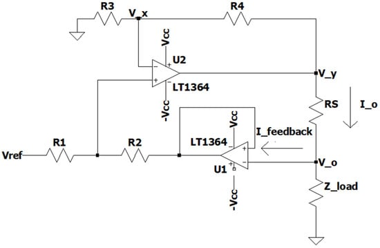
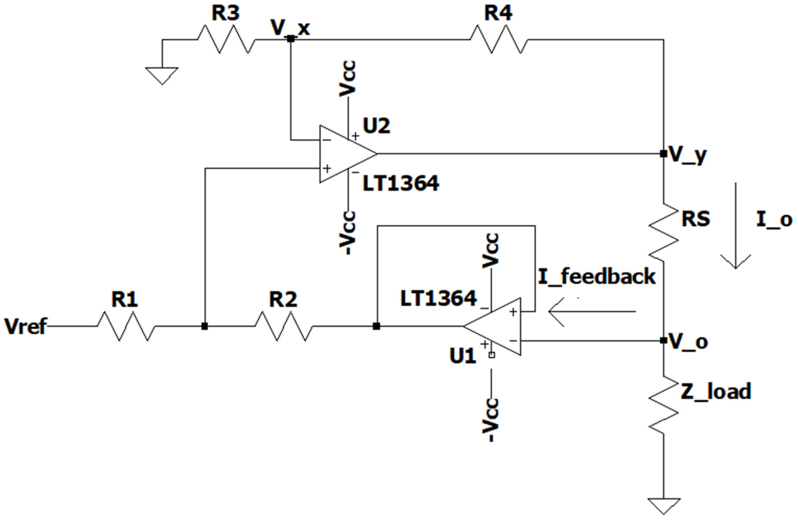
The current source circuit used in this article is an improved Howland current pump with buffer as shown in Figure 6, which has the added benefit of minimizing error by practically eliminating current due to the added buffer [15].
Figure 6.
Improved Howland current pump with buffer circuit.
Considering the impact of component errors on the output current accuracy of the Howland current source circuit, the following derivation is performed:
Based on the virtual ground characteristic of the OPA, Equation (5) can be obtained.
where , , , and represent the resistance errors of resistors , , , and , respectively, and . Simplifying Equation (5) yields Equation (6).
To simplify the analysis, set and , which gives:
Equation (7) can be simplified through basic algebraic operations to obtain Equation (8).
Since , , and will be much larger than the error terms, Equation (8) can be approximated as:
Simplifying (9) gives:
Based on (10), the output current is:
Through Equation (11), the output current can be separated into the ideal output current and the output current error .
Based on relation (15), the output current error can be designed according to the application requirements.
where is the maximum acceptable error percentage in the application.
2.3.2. Current Source Circuit OPA Dissipation
The power consumption of the OPA can be divided into internal power , as expressed by the following equation:
where is the static current of the OPA, is the supply voltage of the OPA, is the output current of the OPA, and is the output voltage of the OPA. The temperature rise of the OPA component can be estimated using Equation (17).
where is the junction temperature of the OPA, is the ambient temperature, and is the thermal resistance (°C/W).
Based on Equations (16) and (17), it is evident that PAM-TI has a significant advantage over traditional TI. Due to the higher stimulation frequency of PAM-TI, it effectively reduces the bioimpedance, thereby lowering the operational amplifier (OPA) supply voltage and output voltage . This not only significantly reduces the current source OPA power dissipation , improving the overall system efficiency, but also results in a lower operating temperature under the same cooling conditions, mitigating the risk of overheating and enhancing the stability during prolonged operation.
2.3.3. Push–Pull Current Source Design
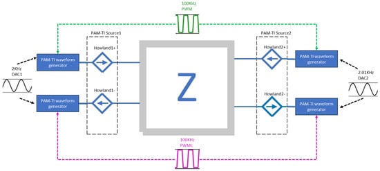
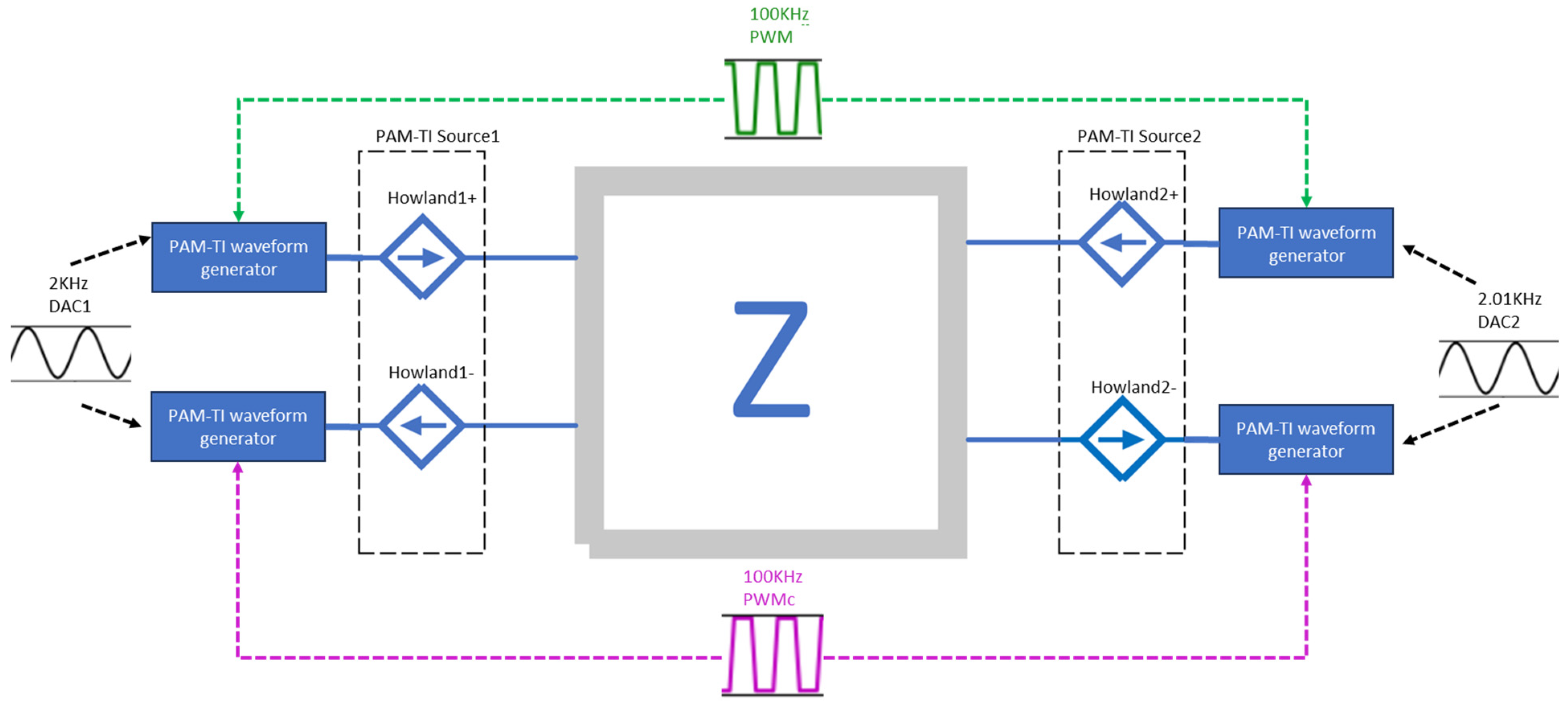
This paper adopts a push–pull current source architecture, using two sets of PAM-TI Source, each of which contains two sets of Howland current sources. In this design, only one MCU is needed to control four sets of Howland current sources, and the MCU’s PWM and PWMc (complementary PWM) are used to perform 100 kHz pulse amplitude modulation and to synchronize each Howland current source, and two sets of DACs are used to generate 2 kHz and 2.01 kHz sine waves, respectively, as shown in Figure 7.
Figure 7.
Push–pull current source architecture.
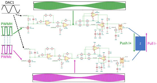
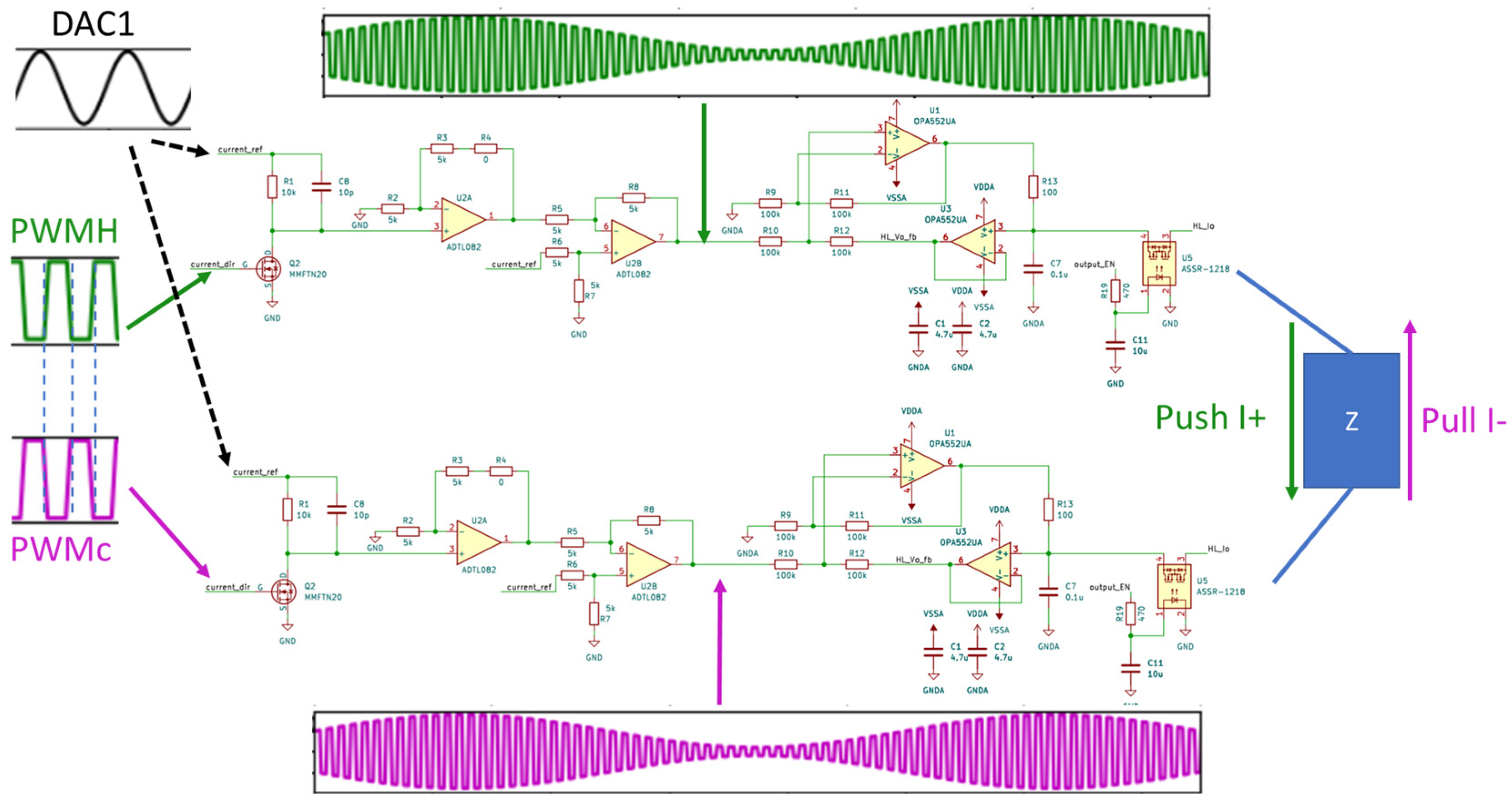
This paper designs a mechanism that can control the current push and pull of the current source and the complementary control method. The following takes the PAM-TI source1 as an example, and the schematic diagram is shown in Figure 7. The MCU can output two sets of symmetrical PMW and PWMc, and through the two sets of DACs of the MCU, DAC1 outputs 2 kHz sinewave and DAC2 outputs 2.01 kHz sinewave, respectively, to generate a PAM-TI waveform. It can be seen from Figure 8 that PWM and PWMc are complementary signals, which also control the current direction of the Howland current source Push I+ and Pull I−.
Figure 8.
Push–pull current control diagram.
Based on a comparison between previous literature and this paper, the focus is on charging current balance, no transformer, and finally the supported current stimulation frequency. The comparison of related neural electrical stimulation device papers is summarized in Table 2. It can be seen that this paper proposes charging current balance control, and a transformer-free electrical stimulation current source is used, and the stimulation frequency can reach 100 kHz due to the use of PAM technology (Ahmedabad, India).
Table 2.
The summary of neural electrical stimulation device.
3. Results
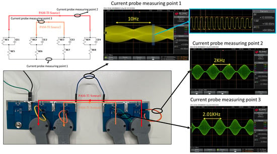
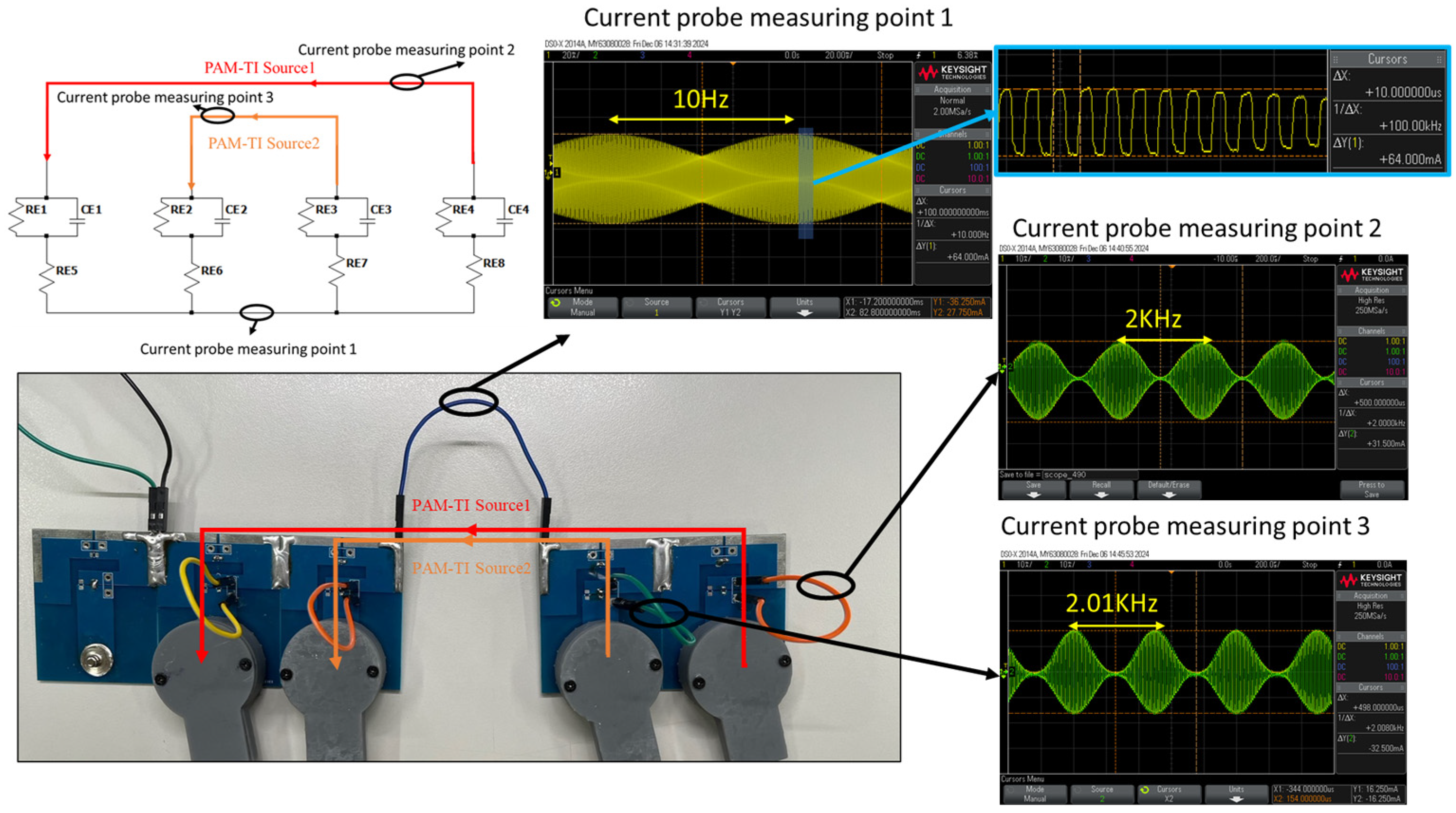
The electrical stimulation circuit proposed in this paper was verified by the nerve equivalent electric circuit proposed by McNeal et al. [26] to observe the waveform of the current and the waveform of interference in the tissue stimulated by our proposed current source. The actual circuit connection diagram is shown in Figure 9. The two pairs of PAM-TI source1 and PAM-TI source2 are connected to the equivalent circuit, and the interference current waveform generated is shown in Figure 9. It can be seen that the interference frequency ∆f = 10 Hz has between 2 kHz and 2.01 kHz current sources.
Figure 9.
The actual circuit connection diagram.
Finally, this paper adopts the electrical simulant agar of the human scalp tissue-mimicking phantom proposed in the paper of Morales-Quezada et al. [27], as shown in Table 3, and places it in a 7 × 7 matrix sampling box made by 3D printing.
Table 3.
The conductivities and compositions of the electrical simulants for a scalp tissue.
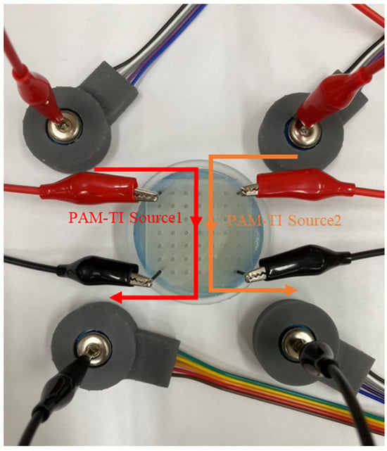
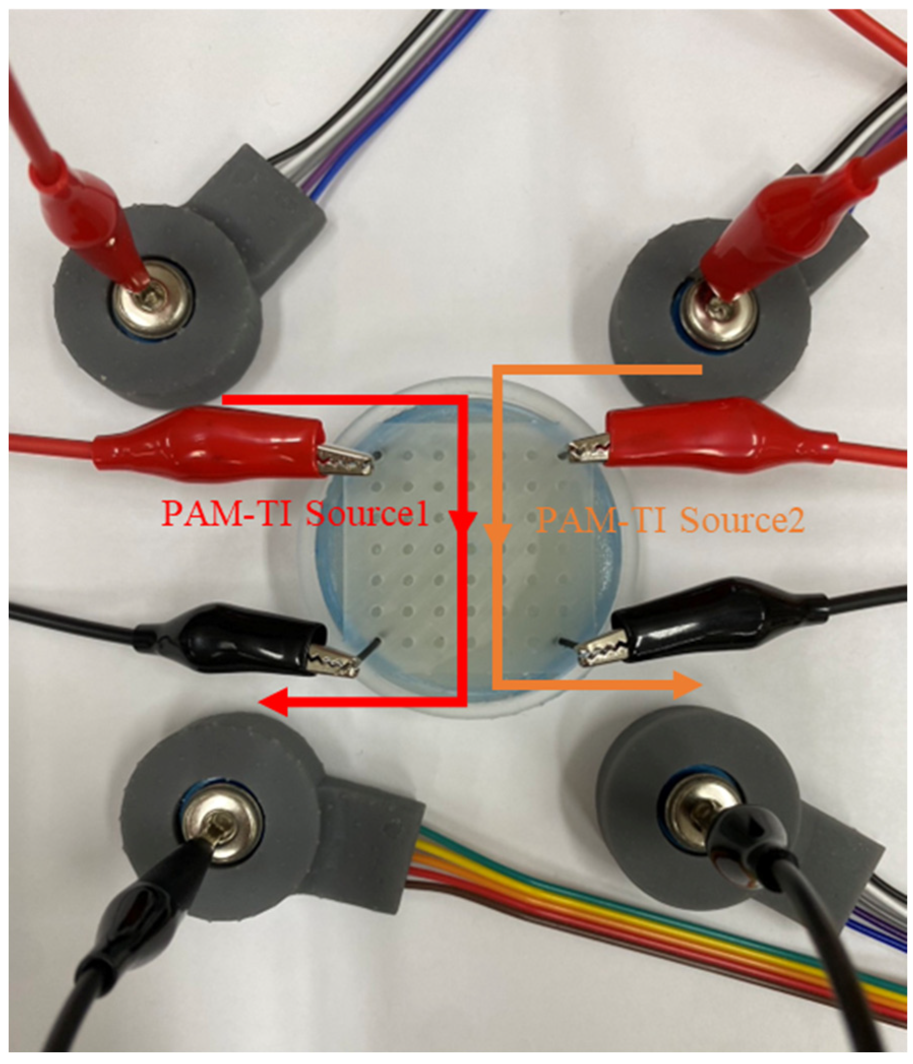
The two PAM-TI sources are placed in the upper left of the sampling box and the lower left for PAM-TI Source1. The upper right and the lower right are PAM-TI Source2. The wiring diagram is shown in Figure 10.
Figure 10.
Agar measurement experiment diagram.
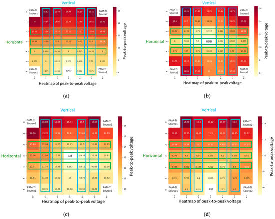
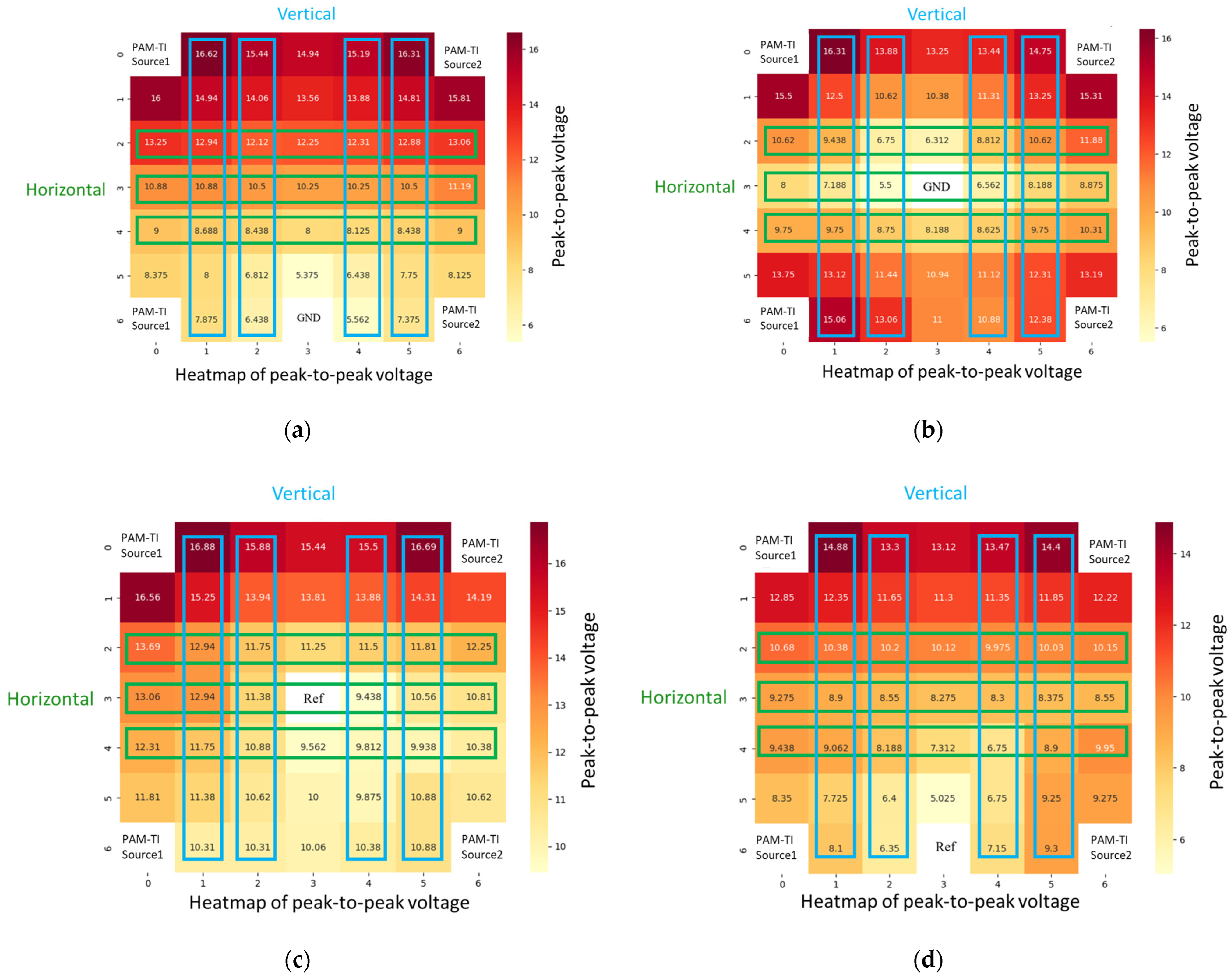
To verify the current directionality of the push–pull current source, PAM-TI Source1 was connected to the upper left/lower left of the sampling box, and PAM-TI Source2 was connected to the upper right/lower right of the sampling box. A probe was then used to record the voltage generated by the current flowing through the tissue-mimicking phantom, allowing us to observe the current flow distribution via the voltage difference. Peak-to-peak voltage (Vpp) measurements were used to generate a heatmap. As shown in Figure 11, a significant voltage difference was observed in the vertical direction, while the voltage difference in the horizontal direction was less pronounced. This experiment aimed to confirm the influence of REF (where only the ground of the measuring probe is connected to the sampling box) or GND (where both the ground of the measuring probe and the stimulator system are connected to the sampling box) on the direction of the current. Therefore, REF or GND was placed at the middle or bottom-center position. It was observed that a slight voltage depression occurred around the reference point or ground, but the vertical and horizontal current directionality remained intact. These observations validate the feasibility of the push–pull current source proposed in this study.
Figure 11.
(a) Heatmap of peak-to-peak voltage measuring with GND as the center; (b) Heatmap of peak-to-peak voltage measuring with GND as the bottom; (c) Heatmap of peak-to-peak voltage measuring with REF as the center; (d) Heatmap of peak-to-peak voltage measuring with REF as the bottom.
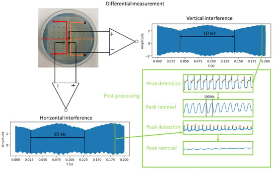
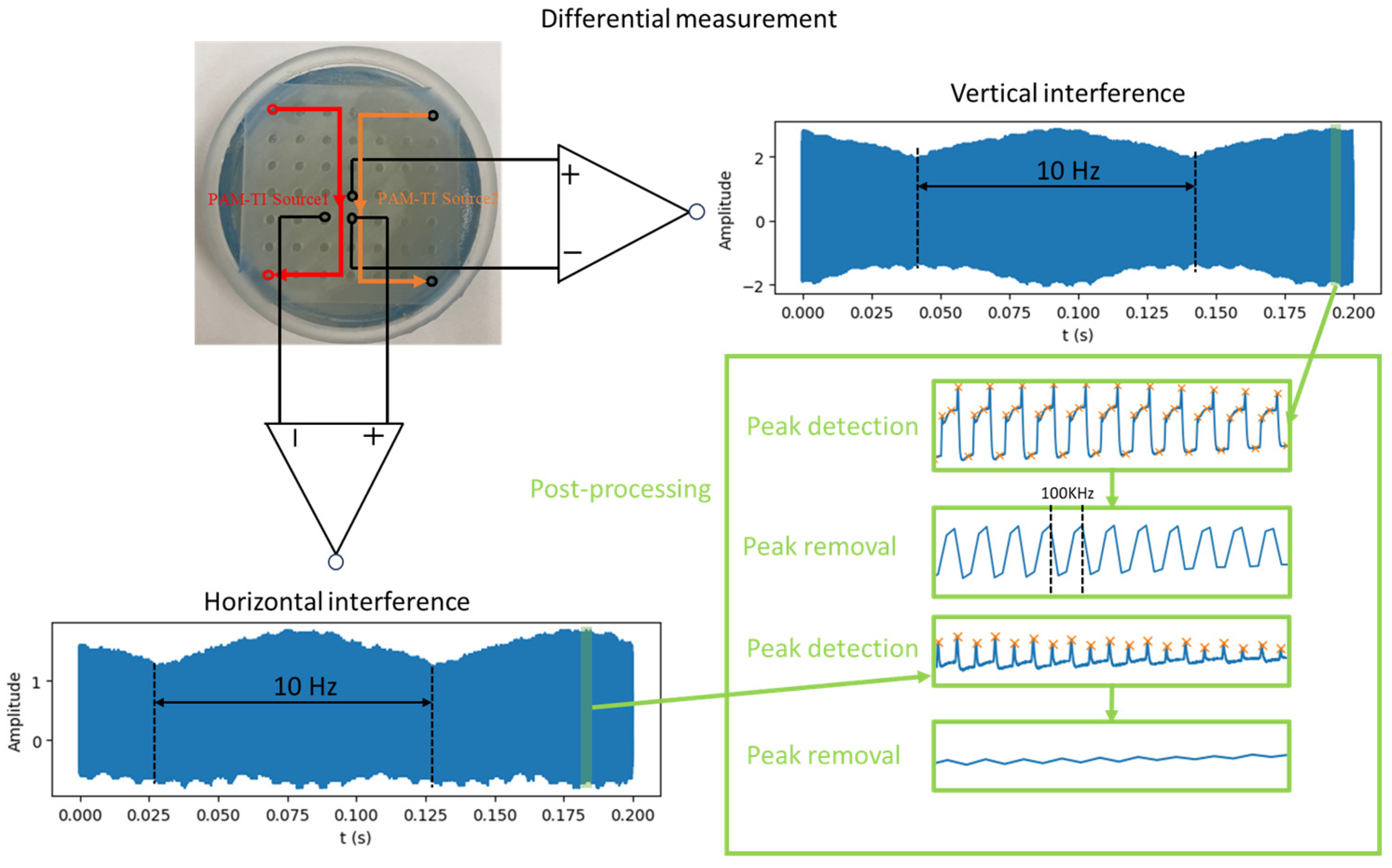
According to the observation results of the previous experiment, the direction of current flows vertically. Therefore, the tissue-mimicking was measured by a differential method to verify the current interference situation. The vertical and the horizontal directions at the center point of the tissue-mimicking phantom can be observed from Figure 12 below. It can be found that there are 10 Hz interference waveforms in both the vertical and horizontal target areas, but after post-processing, the vertical differential voltage amplitude and the 100 kHz carrier wave are more obvious horizontally.
Figure 12.
Differential measurement in the vertical and the horizontal directions of the center point.
4. Discussion
In this paper, we provide a detailed explanation of the design methodology for the electrical stimulation device. We propose utilizing PAM technology to modulate the carrier frequency to 100 kHz, achieving a frequency resolution of 10 Hz without requiring an expensive high-end high-frequency DAC. This approach reduces the impedance of skin tissue, conserving more energy for effective tissue stimulation. The proposed high frequency PAM-TI stimulation device has the following features:
- Through the PAM architecture, we can modulate low-frequency waveforms (e.g., 2 kHz and 2.01 kHz in this study) to high frequencies (e.g., 100 kHz). This method avoids the use of expensive high-end high-frequency DACs while precisely maintaining the slight frequency difference between the two waveforms (e.g., 10 Hz). This technique utilizes high-frequency modulation to reduce the impedance of skin tissue, thereby conserving more energy for tissue stimulation.
- This study adopts complementary PWM signals and a push–pull circuit design in the PAM-TI technique to maximize the phase difference between the two current sources in the TI system, ensuring charge balance and minimizing tissue damage during stimulation, thus addressing safety concerns related to unbalanced charge injection at the tissue-electrode interface.
- To minimize attenuation, the study integrates the PAM circuit directly into the electrode, ensuring that the high-frequency signal is generated close to the body. This approach prevents the degradation of the signal in long wires. Additionally, a dry pin-type spring-loaded electrode is used to overcome the interference caused by hair when placed on the head.
Based on the above characteristics of this device, the PAM-TI current stimulation device was proposed, and the interference waveform and interference frequency were verified through the neural equivalent circuit. Finally, the current directionality of the push–pull current source structure was explored through a scalp tissue phantom made of agar and saline. In this paper, we introduce PAM-TI and analyze its advantages over traditional TI, particularly in increasing stimulation frequency, reducing biological impedance, enhancing system efficiency, and improving heat dissipation. However, the impact of PAM-TI on safety and neural stimulation efficiency requires further validation and evaluation. In future research, we will conduct biological experiments to further assess the effectiveness of PAM-TI in real biological environments and ensure its safety and efficacy for clinical applications.
Author Contributions
Conceptualization, J.-H.B. and S.-C.H.; methodology, J.-H.B.; software, S.-C.H.; validation, J.-H.B., S.-C.H. and S.-J.L.; formal analysis, T.-C.C. and C.-J.H.; investigation, T.-C.C. and C.-J.H.; resources, K.-K.S.; data curation, S.-J.L.; writing—original draft preparation, J.-H.B.; writing—review and editing, P.-L.L.; visualization, J.-H.B.; supervision, P.-L.L.; project administration, P.-L.L.; funding acquisition, P.-L.L. All authors have read and agreed to the published version of the manuscript.
Funding
This research was funded by National Science and Technology Council, Taiwan, grant number 113-2640-B-008-001, 113-2221-E-008-067-MY3, and 113-2321-B-075-008. The APC was funded by 113-2640-B-008-001.
Institutional Review Board Statement
Not applicable.
Informed Consent Statement
Not applicable.
Data Availability Statement
The data presented in this study are available on request from the corresponding author.
Conflicts of Interest
The authors declare no conflicts of interest.
References
- Khabarova, E.A.; Denisova, N.P.; Dmitriev, A.B.; Slavin, K.V.; Verhagen Metman, L. Deep Brain Stimulation of the Subthalamic Nucleus in Patients with Parkinson Disease with Prior Pallidotomy or Thalamotomy. Brain Sci. 2018, 8, 66. [Google Scholar] [CrossRef] [Scilit] [PubMed]
- Lozano, A.M.; Fosdick, L.; Chakravarty, M.M.; Leoutsakos, J.-M.; Munro, C.; Oh, E.; Drake, K.E.; Lyman, C.H.; Rosenberg, P.B.; Anderson, W.S.; et al. A Phase II Study of Fornix Deep Brain Stimulation in Mild Alzheimer’s Disease. J. Alzheimer’s Dis. 2016, 54, 777–787. [Google Scholar] [CrossRef] [Scilit] [PubMed]
- Laxpati, N.G.; Kasoff, W.S.; Gross, R.E. Deep brain stimulation for the treatment of epilepsy: Circuits, targets, and trials. Neurotherapeutics 2014, 11, 508–526. [Google Scholar] [CrossRef] [Scilit]
- Olson, M.C.; Shill, H.; Ponce, F.; Aslam, S. Deep brain stimulation in PD: Risk of complications, morbidity, and hospitalizations: A systematic review. Front. Aging Neurosci. 2023, 15, 1258190. [Google Scholar] [CrossRef] [Scilit]
- Grossman, N.; Bono, D.; Dedic, N.; Kodandaramaiah, S.B.; Rudenko, A.; Suk, H.J.; Cassara, A.M.; Neufeld, E.; Kuster, N.; Tsai, L.H.; et al. Noninvasive Deep Brain Stimulation via Temporally Interfering Electric Fields. Cell 2017, 169, 1029–1041.e16. [Google Scholar] [CrossRef] [Scilit] [PubMed]
- Alvarez, D.M.; Serrano-Munoz, D.; Fernandez-Perez, J.J.; Gomez-Soriano, J.; Avendano-Coy, J. Effect of percutaneous electrical stimulation with high-frequency alternating currents at 30 kHz on the sensory-motor system. Front. Neurosci. 2023, 17, 1048986. [Google Scholar] [CrossRef] [Scilit] [PubMed]
- Kilgore, K.L.; Bhadra, N. Nerve conduction block utilising high-frequency alternating current. Med. Biol. Eng. Comput. 2004, 42, 394–406. [Google Scholar] [CrossRef] [Scilit] [PubMed]
- Yang, L.; Dai, M.; Xu, C.; Zhang, G.; Li, W.; Fu, F.; Shi, X.; Dong, X. The Frequency Spectral Properties of Electrode-Skin Contact Impedance on Human Head and Its Frequency-Dependent Effects on Frequency-Difference EIT in Stroke Detection from 10Hz to 1MHz. PLoS ONE 2017, 12, e0170563. [Google Scholar] [CrossRef] [Scilit]
- Rosell, J.; Colominas, J.; Riu, P.; Pallas-Areny, R.; Webster, J.G. Skin impedance from 1 Hz to 1 MHz. IEEE Trans. Biomed. Eng. 1988, 35, 8. [Google Scholar] [CrossRef] [Scilit]
- Wang, Y.-C.; Wang, P.-F.; Pan, H.-C.; Lin, C.-Y.; Hsu, H.-T.; Liu, Z.-H.; Lee, P.-L. Intracranial Monitoring to Verify Novel Transcranial Electric Stimulation in an Epileptic Swine Model. Electronics 2022, 11, 2195. [Google Scholar] [CrossRef] [Scilit]
- Zhang, Z.; Lin, B.S.; Wu, C.G.; Hsieh, T.H.; Liou, J.C.; Li, Y.T.; Peng, C.W. Designing and Pilot Testing a Novel Transcranial Temporal Interference Stimulation Device for Neuromodulation. IEEE Trans. Neural Syst. Rehabil. Eng. 2022, 30, 1483–1493. [Google Scholar] [CrossRef] [Scilit]
- Eickhoff, S.; Jarvis, J.C. Pulse Shaping Strategies for Electroceuticals: A Comprehensive Survey of the Use of Interphase Gaps in Miniature Stimulation Systems. IEEE Trans. Biomed. Eng. 2021, 68, 1658–1667. [Google Scholar] [CrossRef] [Scilit] [PubMed]
- Merrill, D.R.; Bikson, M.; Jefferys, J.G. Electrical stimulation of excitable tissue: Design of efficacious and safe protocols. J. Neurosci. Methods 2005, 141, 171–198. [Google Scholar] [CrossRef] [Scilit]
- Tarulli, M.; Huerta, S.C.; Prodic, A.; Popovic, M.R.; Lehn, P.W. Merged Flyback–SC-Based Output Stage for Versatile Portable Transcutaneous Electrical Stimulators. IEEE J. Emerg. Sel. Top. Power Electron. 2016, 4, 318–331. [Google Scholar] [CrossRef] [Scilit]
- Lam, I.V. Analysis of Improved Howland Current Pump Configurations; Texas Instruments: Dallas, TX, USA, 2023. [Google Scholar]
- Nahman, N. A discussion on the transient analysis of coaxial cables considering high-frequency losses. IRE Trans. Circuit Theory 1962, 9, 144–152. [Google Scholar] [CrossRef]
- True, K.M. Long transmission lines and data signal quality. Natl. Semicond. Appl. Note 1992, 808, 1–23. [Google Scholar]
- Hinrichs, H.; Scholz, M.; Baum, A.K.; Kam, J.W.Y.; Knight, R.T.; Heinze, H.J. Comparison between a wireless dry electrode EEG system with a conventional wired wet electrode EEG system for clinical applications. Sci. Rep. 2020, 10, 5218. [Google Scholar] [CrossRef] [Scilit] [PubMed]
- Hsu, H.T.; Shyu, K.K.; Hsu, C.C.; Lee, L.H.; Lee, P.L. Phase-Approaching Stimulation Sequence for SSVEP-Based BCI: A Practical Use in VR/AR HMD. IEEE Trans. Neural Syst. Rehabil. Eng. 2021, 29, 2754–2764. [Google Scholar] [CrossRef] [Scilit] [PubMed]
- Esmaeilpour, Z.; Kronberg, G.; Reato, D.; Parra, L.C.; Bikson, M. Temporal interference stimulation targets deep brain regions by modulating neural oscillations. Brain Stimul. 2021, 14, 55–65. [Google Scholar] [CrossRef] [Scilit]
- De Lima, J.A.; Cordeiro, A.S. A low-cost neurostimulator with accurate pulsed-current control. IEEE Trans. Biomed. Eng. 2002, 49, 497–500. [Google Scholar] [CrossRef] [Scilit] [PubMed]
- Valente, V.; Demosthenous, A.; Bayford, R. A tripolar current-steering stimulator ASIC for field shaping in deep brain stimulation. IEEE Trans. Biomed. Circuits Syst. 2012, 6, 197–207. [Google Scholar] [CrossRef] [Scilit]
- Lin, C.Y.; Chen, W.L.; Ker, M.D. Implantable stimulator for epileptic seizure suppression with loading impedance adaptability. IEEE Trans. Biomed. Circuits Syst. 2013, 7, 196–203. [Google Scholar] [CrossRef] [Scilit] [PubMed]
- Kouzani, A.Z.; Kale, R.P.; Zarate-Garza, P.P.; Berk, M.; Walder, K.; Tye, S.J. Validation of a Portable Low-Power Deep Brain Stimulation Device Through Anxiolytic Effects in a Laboratory Rat Model. IEEE Trans. Neural Syst. Rehabil. Eng. 2017, 25, 1365–1374. [Google Scholar] [CrossRef] [Scilit]
- Corva, D.M.; Parke, B.; West, A.; Doeven, E.H.; Adams, S.D.; Tye, S.J.; Hashemi, P.; Berk, M.; Kouzani, A.Z. SmartStim: An Artificial Intelligence Enabled Deep Brain Stimulation Device. IEEE Trans. Med. Robot. Bionics 2024, 6, 674–684. [Google Scholar] [CrossRef] [Scilit]
- McNeal, D.R. Analysis of a model for excitation of myelinated nerve. IEEE Trans. Biomed. Eng. 1976, 4, 329–337. [Google Scholar] [CrossRef] [Scilit] [PubMed]
- Morales-Quezada, L.; El-Hagrassy, M.M.; Costa, B.; McKinley, R.A.; Lv, P.; Fregni, F. Transcranial Direct Current Stimulation Optimization—From Physics-Based Computer Simulations to High-Fidelity Head Phantom Fabrication and Measurements. Front. Hum. Neurosci. 2019, 13, 388. [Google Scholar] [CrossRef] [Scilit]

Disclaimer/Publisher’s Note: The statements, opinions and data contained in all publications are solely those of the individual author(s) and contributor(s) and not of MDPI and/or the editor(s). MDPI and/or the editor(s) disclaim responsibility for any injury to people or property resulting from any ideas, methods, instructions or products referred to in the content. |
© 2025 by the authors. Licensee MDPI, Basel, Switzerland. This article is an open access article distributed under the terms and conditions of the Creative Commons Attribution (CC BY) license (https://creativecommons.org/licenses/by/4.0/).