


Abstract
Magnesium alloys are attractive biodegradable biomaterials, but their high corrosion rate in physiological fluids limits their clinical use. Polymeric coatings with tailored architecture offer a route to control degradation more precisely than commercial biopolymers. Herein, a grafted copolymer of poly(2-hydroxyethyl methacrylate) and polycaprolactone (PHEMA-g-PCL) via a one-pot combination of reversible addition-fragmentation chain-transfer (RAFT) polymerization and ring-opening polymerization (ROP), yielded a copolymer with Mn of 63.9 kg∙mol−1 and Mw/Mn ratio of 1.21, confirmed by Size Exclusion Chromatography (SEC). The chemical structure of the copolymer was confirmed by Nuclear Magnetic Resonance (NMR) and Fourier Transformation Infrared (FTIR) spectroscopy. The alloy substrate, a hot-rolled Mg-Y-Gd-Zr alloy, was dip-coated using 5 wt.% and 10 wt.% PHEMA-g-PCL solutions, and corrosion behavior was evaluated by hydrogen evolution and pH monitoring during immersion in Hank’s solution at 37 °C. Uncoated samples corroded fastest ((0.0145 ± 0.0009) mL·mm−2·h−1) and perforated within 3 days, whereas the 10 wt.% PHEMA-g-PCL coating, which formed a continuous film, reduced the corrosion rate to ((0.0045 ± 0.0002) mL·mm−2·h−1) and preserved structural integrity for over 170 h. The 5 wt.% coating only partially covered the substrate, resulting in more variable corrosion behavior, (0.0068 ± 0.0029) mL·mm−2·h−1. These results establish PHEMA-g-PCL as a proof-of-concept coating strategy for tuning Mg alloy degradation.
1. Introduction
Magnesium (Mg) alloys are promising biomaterials for non-permanent orthopedic implants, owing to their remarkable biocompatibility, biodegradability, and bone-like mechanical properties [1]. However, uncontrolled biodegradability may lead to a high corrosion rate in body fluids [2], resulting in undesirable consequences, such as loss of mechanical integrity and tissue damage before full tissue restoration [3,4,5]. To overcome these drawbacks, several approaches have been investigated, for example, applying different alloy designs [6,7], surface modifications [8,9], and coatings [5,10,11,12,13,14]. The use of coatings can be a versatile and tunable approach, spreading the functional scope of the alloy-media interface. Polymeric coatings present strong potential for functionalization. Commercial biopolymers are widely used as coatings and have demonstrated satisfactory results in minimizing the corrosion rate of Mg alloys [5,10]. However, commercial polymers offer limited options for size, morphology, and structure of the polymeric chains. This lack of choices can obstruct the optimization of coating properties such as adhesion, degradation rate, and barrier function. Therefore, the development of coatings using polymers with precisely engineered architectures is a promising strategy to overcome these limitations.
Controllable polymerization techniques have demonstrated reliability and versatility in designing polymers [15,16]. Over the past three decades, reversible-deactivation radical polymerization (RDRP), particularly reversible addition–fragmentation chain transfer (RAFT) polymerization, has established itself as a powerful methodology for the synthesis of precision polymeric materials from a wide range of monomers [17]. Furthermore, ring-opening polymerization (ROP) has been used to synthesize biopolymers, such as poly-ι-lactic acid (PLLA) and poly-ε-caprolactone (PCL), which have been extensively investigated for biomedical applications due to their tunable degradation behavior and mechanical properties [18,19]. The combination of RAFT and ROP enables the development of block and graft copolymers with tailored morphologies and interfacial properties, expanding their applicability in drug delivery systems, smart materials, and protective coatings for metallic substrates [18,20,21,22,23].
Yang and collaborators [12] reported a significant improvement in the corrosion resistance of magnesium alloys using a PCL coating doped with infrared-induced self-healing particles. Similarly, Huang et al. [5] developed an electrografted PCL coating for a Mg–2Zn–0.46Y–0.5Nd (wt.%) alloy, demonstrating improvements in microstructural stability, degradation behavior, and cytocompatibility. Xu and Yamamoto [13] investigated the influence of the average molar mass of PCL and PLLA coatings on magnesium corrosion performance, observing that PCL films exhibited a semicrystalline structure and developed surface bulging after 7 days of immersion. Furthermore, Bedair and collaborators [14] evaluated the effect of wettability and thickness of graft copolymers based on poly(2-hydroxylethyl methacrylate) (PHEMA) and PCL applied as coatings to Co–Cr alloys for drug-eluting stent applications. They reported that hydrophobic PHEMA-g-PCL brush layers maintained coating stability for up to 8 weeks, likely due to chain entanglement within the PCL segments, which enhanced structural integrity.
Among Mg alloys, Mg-Y-Gd-Zr systems (such as WV43) exhibit excellent mechanical properties and biocompatibility owing to grain refinement and solid solution strengthening by rare-earth elements [24]. However, the precipitation of second phases (e.g., Mg24Y5) promotes severe micro-galvanic corrosion in physiological solutions, necessitating effective surface protection [25]. While commercial homopolymers like PCL have been applied to Mg alloys, their single-component nature limits independent tuning of coating adhesion, wettability, and degradation kinetics [13,18,19]. Graft copolymers offering dual functionality (such as a PHEMA backbone bearing hydroxyl groups for interfacial wetting and PCL side-chains providing hydrophobic barrier protection) offer a versatile alternative [18,20,21,22,23]. Although PHEMA-g-PCL graft architectures have demonstrated stability on inert metallic substrates like Co–Cr [14], their effectiveness on highly reactive, biodegradable rare-earth Mg alloys remains unexplored. To address this gap, the specific objectives of this work were as follows: (i) to synthesize and characterize a PHEMA-g-PCL graft copolymer via a one-pot simultaneous RAFT and ROP polymerization; (ii) to evaluate the surface coverage and morphological characteristics of dip-coated hot-rolled Mg-Y-Gd-Zr (WV43) alloy substrates using 5 wt.% and 10 wt.% copolymer solutions, aiming to determine the minimal polymer threshold required to form a continuous protective layer over the substrate surface; and (iii) to assess the protective performance of these engineered coatings and their impact on the corrosion kinetics and mechanism of the Mg alloy during immersion in Hank’s solution at 37 °C.
2. Results and Discussion
2.1. PHEMA-g-PCL Characterizations
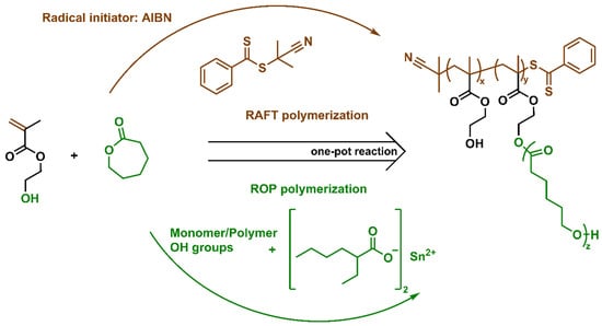
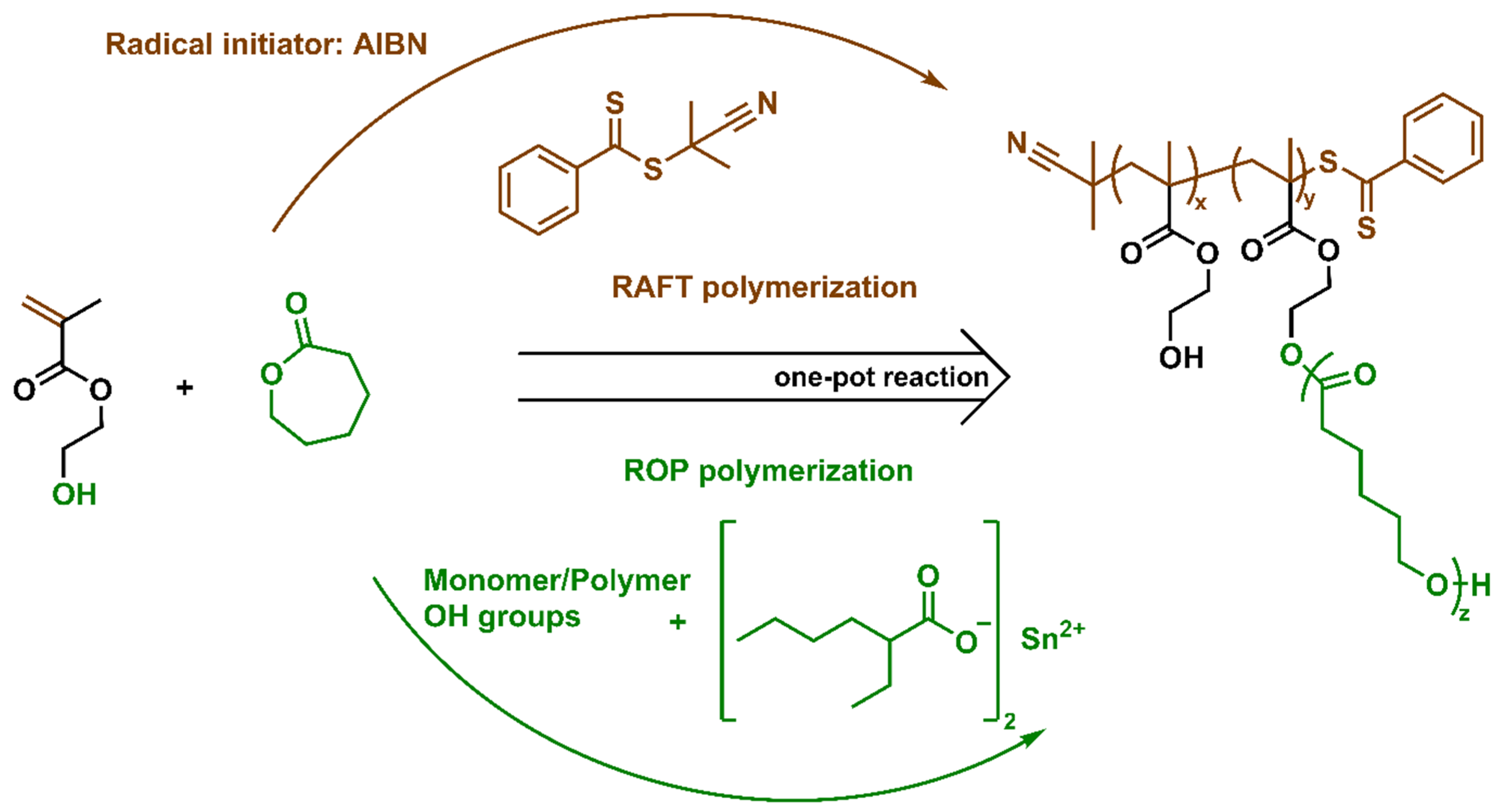
The chosen route to synthesize a copolymer based on PHEMA grafted with PCL was based on the protocol of Barner-Kowollik and coworkers [26]. Figure 1 presents the general reaction scheme of the copolymerization via RAFT and ROP one-pot polymerization, clarifying the different reaction paths that occur simultaneously. RAFT polymerization is based on the radical chain growth of the vinylic group of HEMA monomer controlled by the RAFT agent mechanism. Using a reliable commercial catalyst (tin(II) 2-ethylhexanoate), the ROP of the ε-CL monomer was carried out in the same reaction flask as the RAFT HEMA polymerization, initiated by the hydroxyl groups of HEMA/PHEMA. The final material expected for this reaction is the copolymer aimed at, as well as the HEMA-CL by-product. However, the by-product is easily removed by two-step precipitation, as described in the protocol followed [26].
Figure 1.
General scheme of the one-pot reaction of RAFT and ROP polymerization of hydroxyethyl methacrylate (HEMA) and ε-caprolactone (ε-CL), where x, y, and z are the degree of polymerization of PHEMA not attached to PCL, PHEMA attached to PCL, and PCL, respectively.
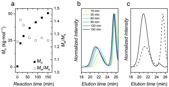
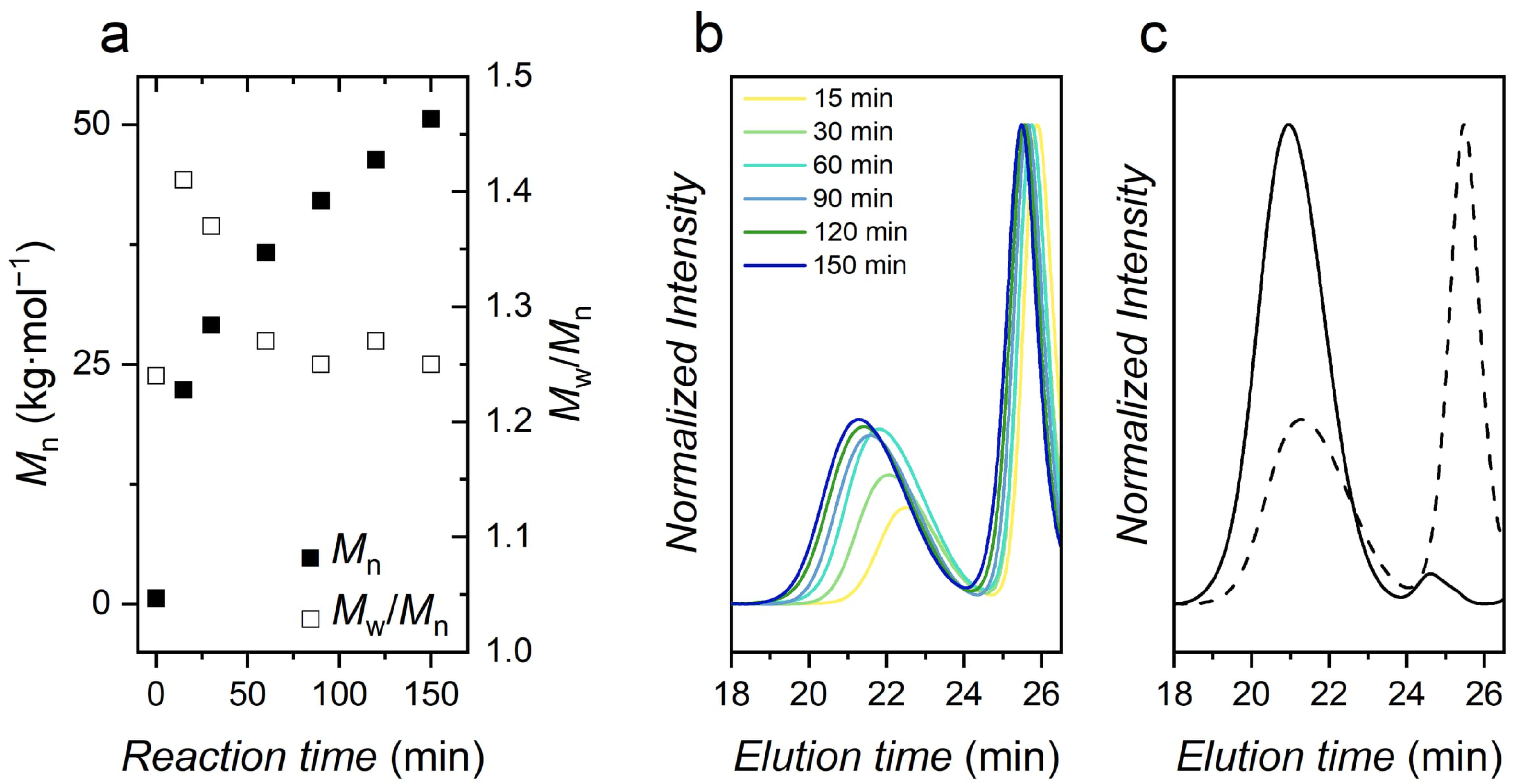
Figure 2a shows the Mn and Mw/Mn through the reaction time. Firstly, a rapid increase of Mn is seen, probably due to the rapid kinetics of ROP polymerization forming the HEMA-PCL homopolymer; meanwhile, RAFT initial non-propagating steps are taking place. After the first 15 min, the derivative of the curve (Figure 2a, solid squares) decreases, and the Mn grows almost linearly to the end of the reaction. Those trends are confirmed in Figure 2b where the polymer signal shifts to lower elution times (higher molar mass), and the area under the signal increases (more polymer mass). The HEMA-PCL product signal at later elution times remains nearly unchanged throughout the reaction, indicating only a very slight change in the average molar mass and total polymer mass produced after the initial 15 min. The reaction was terminated after 150 min by removing the flask from the heating bath and opening it to air. The Mn reached 50.6 kg∙mol−1. The Mw/Mn ratio of the lower elution time peak (supposedly the PHEMA-PCL copolymer) decreased along the reaction time, reaching the final value of 1.25. Figure 2b shows SEC chromatogram snapshots of the reaction. An intense signal on late elution time (around 1200 g∙mol−1) appeared in all chromatograms beginning in the early stages of the reaction. This signal corresponds to the HEMA-PCL homopolymer, which can be mostly eliminated, as previously described [26]. Figure 2c shows the SEC chromatograms of the copolymer before and after purification. Before purification, the HEMA-PCL compound was predominant. After purification, this by-product represents only a trace remaining in the final material. Furthermore, the increased average molar mass (Mn = 63.9 kg∙mol−1) of the copolymer and slightly decreased Mw/Mn ratio to 1.21 after purification are probably due to the dependence of selective solubility on the chain’s molar mass.
Figure 2.
SEC analysis of the synthesis of PHEMA-g-PCL: (a) evolution of Mn (■) and Mw/Mn (□) during reaction time; (b) chromatograms of aliquots over time throughout the polymerization; and (c) chromatograms before (dashed line) and after (solid line) the purification procedure.
The NMR analysis (1H, 13C and HSQC) confirmed the structure of the purified PHEMA-g-PCL. The FTIR spectrum showed the presence of many functional groups of the purified copolymer, especially the free OH groups band from both PHEMA and PCL (see Figure S1). Through the integral of the signals, one might note a greater predominance of PCL on the copolymer (see Figure S2). Using isolated peaks of PHEMA (3.82 ppm) and PCL (3.64 ppm), the HEMA grafting density was 92%, which was roughly estimated through Equation (S1). The higher PCL content in the copolymer reflected the difficulty in identifying PHEMA signals in the 13C spectrum (see Figure S3); however, HSQC confirmed 1H signals correlating to 13C of PHEMA (see Figure S4). The CH2 backbone hydrogens (a and e) and the ethyl hydrogens (h) signals appeared on the HSQC spectrum even though no clear 13C signal was shown.
2.2. Mg-Alloy Characterizations
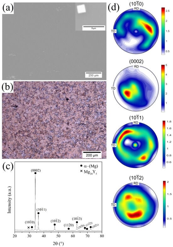
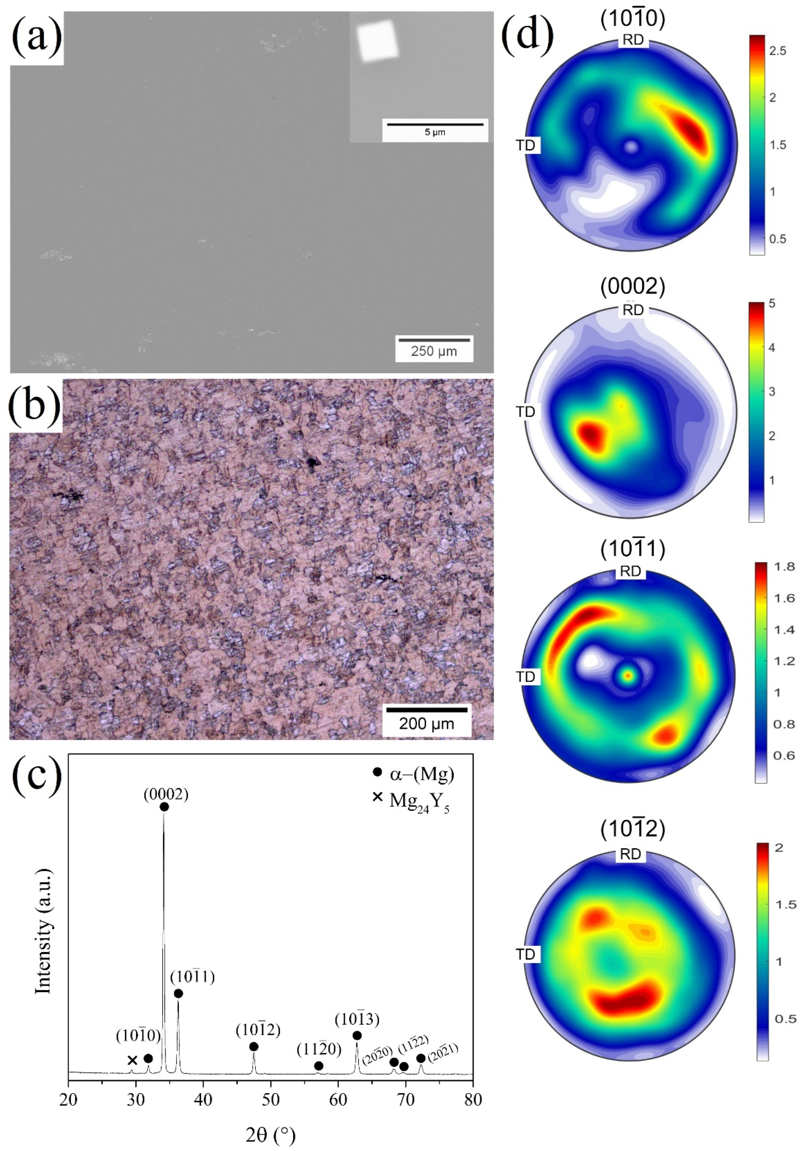
Figure 3 shows microstructural features of the hot rolled WV43 substrate. Figure 3a exhibits a SEM/BSE micrograph with a microstructure consisting of the α-(Mg) matrix and precipitates dispersed. In high magnification, cuboids morphology can be observed. Furthermore, recrystallized grains with an average grain size of 14.3 µm ± 1.1 μm were observed, as shown by LOM micrograph in Figure 3b. Additionally, an intense peak of basal plane (0002) of the α-(Mg) matrix can be observed in the diffraction pattern of Figure 3c. The pole figures exhibited in Figure 3d reveal a weakened and split basal texture after hot rolling, consistent with recrystallization in rare-earth-containing magnesium alloys. The (0002) pole figure shows a moderate maximum intensity (~5 m.r.d.) with the basal poles tilted away from the normal direction (ND). Such behavior is characteristic of Mg–Y–Gd alloys, in which solute drag and particle-stimulated nucleation modify the orientation selection during recrystallization. The redistribution of intensity toward prismatic (100) and pyramidal ((101), (102)) components suggests the activation of non-basal slip systems and a reduced dominance of the typical strong basal texture. This weakened and more diffuse texture is commonly associated with improved ductility and reduced mechanical anisotropy, highlighting the role of Y and Gd additions in tailoring the recrystallized microstructure and crystallographic texture of the WV43 alloy.
Figure 3.
(a) SEM/BSE micrograph, (b) LOM micrograph, (c) XRD diffractogram, and (d) XRD diffraction pole figures ((100), (0002), (101), and (102)) of the hot-rolled WV43 alloy showing the recrystallized texture.
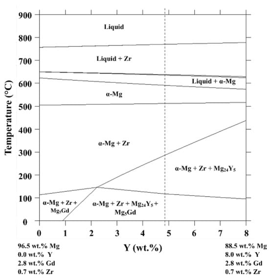
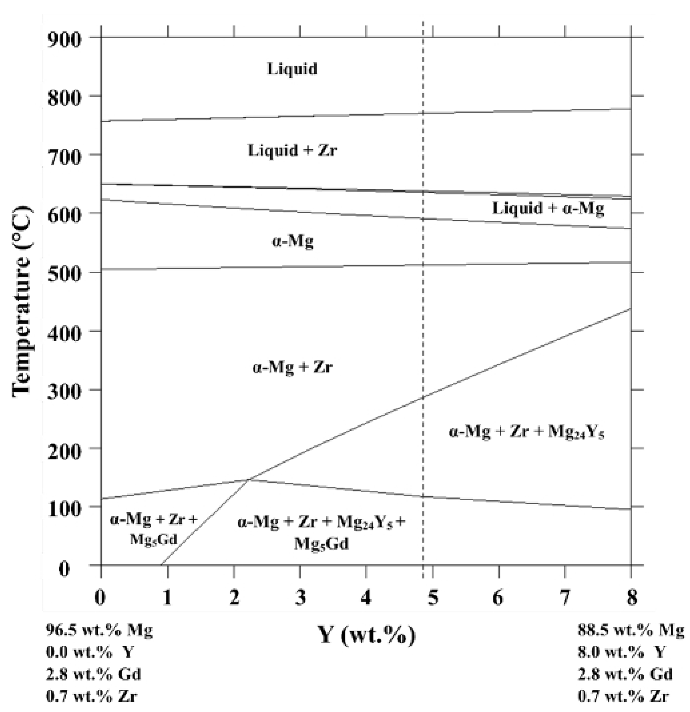
Regarding the precipitates dispersed throughout the α-(Mg) matrix, the XRD diffractogram (Figure 3c) presents peaks of the Mg24Y5 phase in addition to those of the α-(Mg) matrix. The Mg24Y5 phase precipitation is predicted by thermodynamic simulations. Figure 4 shows a vertical section at 2.8 wt.% of Gd and 0.7 wt.% of Zr from the Mg-Gd-Y-Zr equilibrium phase diagram, where the blue line represents the WV43 alloy. The vertical section has a single-phase phase field of the α-(Mg) phase in a range of between 512 °C and 590 °C. Thus, during the dwell time at 525 °C of the homogenization heat treatment, a complete dissolution of precipitates is expected. As the ingot cooling after the homogenization heat treatment was carried out in laboratory atmosphere (around 25 °C), the precipitation of Zr, Mg24Y5, and Mg5Gd phases was predicted. At room temperature, a mole fraction of 0.07 is predicted for the Mg24Y5 phase, while small fractions of 0.002 and 0.02 are expected for the Zr solid solution and Mg5Gd, respectively.
Figure 4.
Vertical section at 2.8 wt.% of gadolinium and 0.7 wt.% of zirconium from the Mg-Gd-Y-Zr equilibrium phase diagram. Dashed line indicates the composition of the WV43 alloy investigated.
Furthermore, clusters of Mg24Y5 precipitates have been observed by Yu et al. [27] for as-cast Mg-1.5Y (wt.%) alloy. Mg24Y5 cuboid-shaped principates have been observed by Milkereit et al. [28] in a wrought WE43-T4 and Yang et al. [29] for a sand-casted Mg-3Y-2Gd-1Nd-0.4Zr (wt.%) alloy. Therefore, in this work, it is suggested that small clusters of Mg24Y5 precipitates nucleated during the solidification of the alloy and did not dissolve during homogenization heat treatments. Additionally, the Mg24Y5 cuboid precipitates formed during the cooling of the homogenization heat treatment, since precipitation is not expected during the hot-rolled process. Zr solid solution and Mg5Gd precipitates were not observed.
2.3. PHEMA-g-PCL Coating and Immersion Test
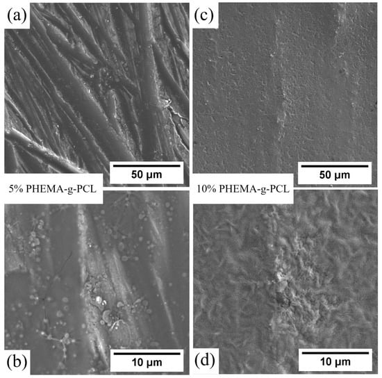
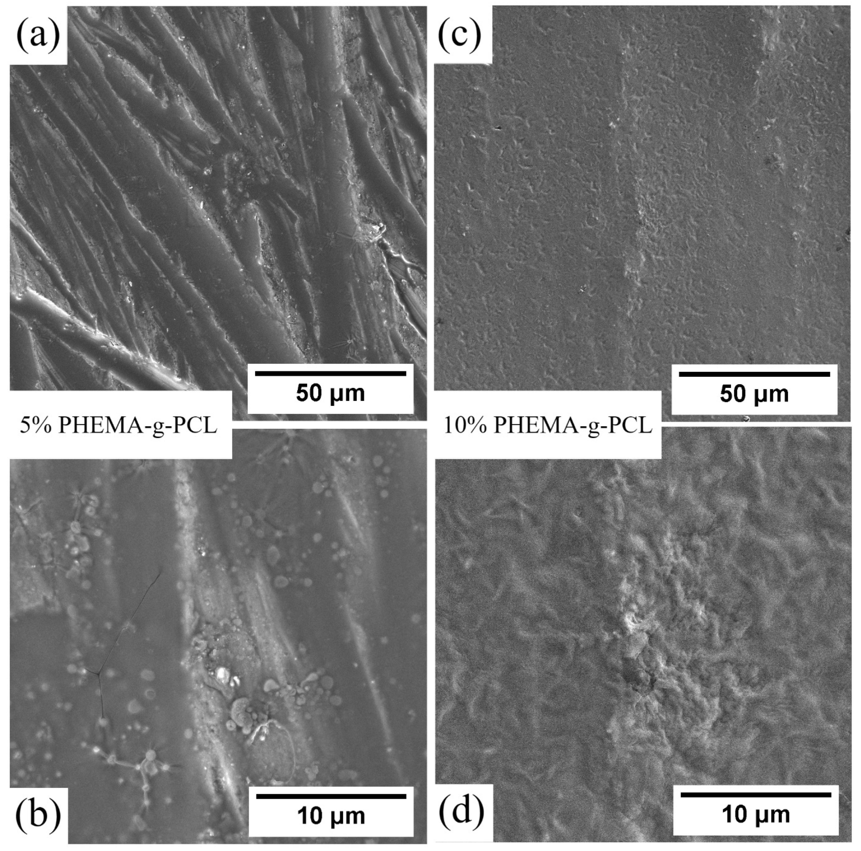
Magnesium alloys intended for use in biological systems typically need to maintain their characteristics for an extended duration, surpassing just a few hours. The objective of this study is solely to establish a proof of concept rather than a definitive biomaterial product. The amount of copolymer employed to achieve a considerable protective effect was very low, with 4.3 μg·mm−2 and 21.3 μg·mm−2 for 5% and 10% PHEMA-g-PCL coating, respectively. Figure 5 shows SEM micrographs of the coated samples. In Figure 5a, it can be observed that the 5% coated sample did not present sufficient polymer to fully cover the surface, as grinding marks from the substrate are still visible. At higher magnification of the polymer-covered region (Figure 5b), cracks and uncoated areas can be identified. In contrast, for the 10% coated sample (Figure 5c), no grinding marks are visible, indicating a more uniform polymer coverage. Moreover, higher magnification (Figure 5d) reveals a continuous coating without observable cracks. This structural continuity of the 10% coating, in contrast to the cracked and partially exposed 5% coating, sets up a clear morphological basis for comparing their protective performance in the immersion tests that follow.
Figure 5.
SEM micrographs of WV43 alloy surfaces coated with PHEMA-g-PCL at different concentrations: 5 wt.% at (a) 2000× and (b) 10,000× magnification and 10 wt.% at (c) 2000× and (d) 10,000× magnification.
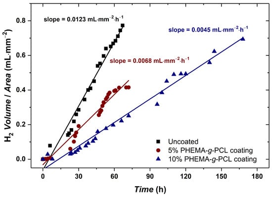
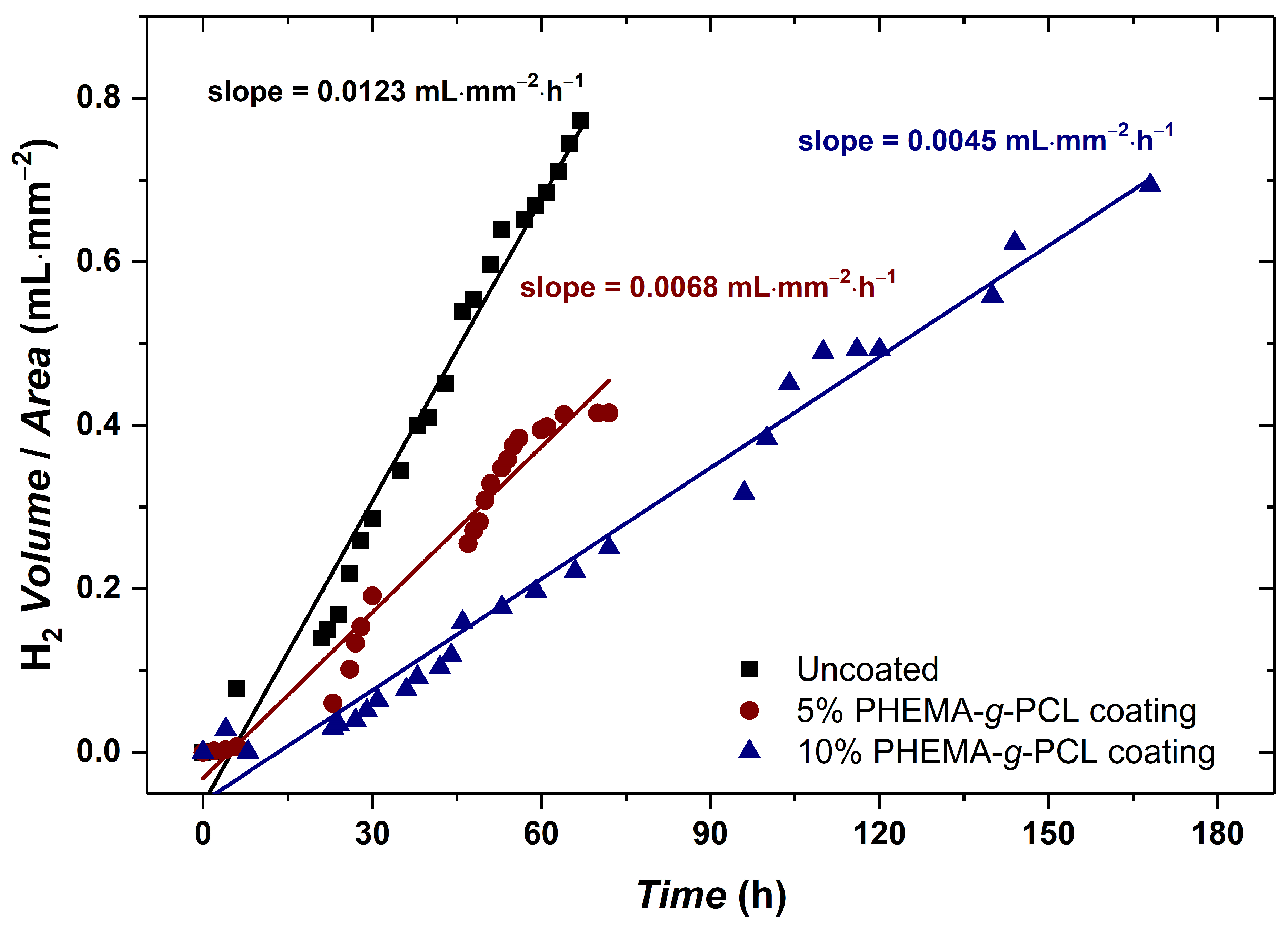
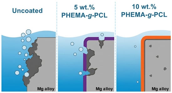
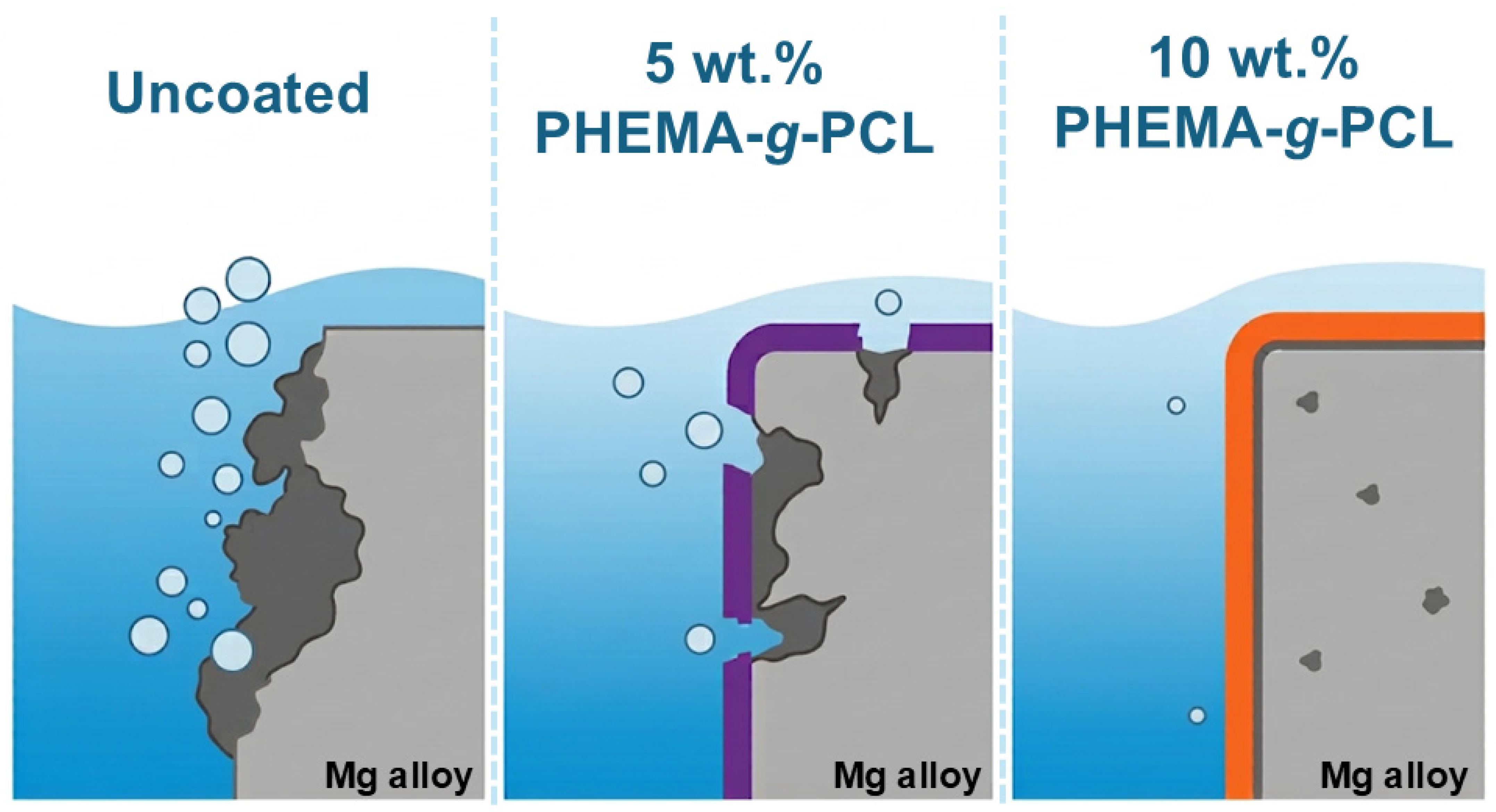
Figure 6 shows the evolution of H2 gas in the immersion experiment on Hank’s solution at 37 °C of three Mg alloy samples (10 mm × 10 mm × 2.5 mm) with two different concentrations of the PHEMA-g-PCL coating preparation: uncoated (control), 5%, and 10% of polymer in the solution. The samples were assessed up to their complete dissolution into the solution. Given the limited number of replicates (duplicates) per condition, the reported standard deviations correspond to the variability in the slope of each curve rather than to a larger statistical sample. The uncoated sample presented the highest corrosion rate with (0.0123 ± 0.0009) mL·mm−2·h−1 as expected. Notably, the fit is better than that of the 5% coating sample, for instance. This fact might be due to constant corrosion across the entire surface of the sample for the uncoated sample. The more scattered data points for the 5% coating could indicate that this concentration was insufficient to properly cover the sample surface, as presented in Figure 5a,b, leading to additional corrosion mechanisms, e.g., pit corrosion. Clearly, despite the hypothesis explaining the higher scattering of the data points, the 5% coating still reduced the corrosion rate to (0.0068 ± 0.0029) mL·mm−2·h−1. Figure 7 overviews the general scheme of the conditions in the immersion tests. The hypothesized mechanisms can be seen where the uncoated samples presented a higher surface exchange with the solution; the 5% coating presented localized corrosion, and the 10% coating presented a more controlled corrosion compared to the other two conditions.
Figure 6.
Evolution of the H2 volume per sample area in time for different conditions of Mg alloys: uncoated (black), coating of 5% (red) and 10% (blue) concentration of PHEMA-g-PCL.
Figure 7.
General scheme of the corrosion mechanisms of Mg alloys in three conditions: uncoated, 5%, and 10% PHEMA-g-PCL coating. The uncoated samples presented a higher surface exchange with the solution; the 5% coating presented localized corrosion; and the 10% coating presented a more controlled corrosion compared to the other two conditions.
Nonetheless, the 10% PHEMA-g-PCL concentration coating sample yielded the lowest corrosion rate of (0.0045 ± 0.0002) mL·mm−2·h−1. Furthermore, the data points throughout the experiment showed higher linearity in the first 72 h, indicating greater control compared to the other conditions. However, after this mark, the data points scattered more around the trend. After 72 h, the coating likely began to delaminate from the substrate, resulting in increased points of higher corrosion on the alloy surface. Alongside mechanical delamination, water uptake through the hydrophilic PHEMA-g-PCL network may have also contributed to this later-stage scatter. Increased hydrophilicity likely aided initial wetting and film formation, but it can also promote electrolyte penetration over prolonged immersion. Distinguishing between these two mechanisms was beyond the scope of the present immersion-based assay. Nonetheless, the sustained performance of the 10% coating up to 170 h suggests that any water uptake effect was secondary to the barrier benefit provided by full surface coverage. Despite the data points becoming more scattered towards the end of the experiment, the 10% coating sample resisted up to 170 h instead of the 72 h performed for both the uncoated and 5% coating. The duplicate investigation confirmed the results seen in Figure 6. The uncoated samples presented the highest corrosion rate among all conditions, with a consistent standard deviation. The 5% coating samples enhanced the performance of Mg samples; however, as previously discussed, the insufficient amount of the polymer to cover the substrate surfaces led to high deviation of the corrosion rate, translated by the significant increase in the standard deviation. Once more, not only did the 10% PHEMA-g-PCL coating enhance the resistance of the Mg alloys, but their samples also demonstrated consistent standard deviation results. Given that the 5% and 10% coatings are chemically identical, this performance gap points to coating coverage and compactness as a significant factor controlling corrosion protection in this system, rather than hydrophilicity itself. One should note that hydrophilicity of the coating also depends on topographic characteristics, not exclusively from chemical components. Surface wettability adjustments can be enhanced from synergistic effects of chemical etching and modification, as seen in, for instance, AA3003 aluminum alloys [30,31]. Although the 10% coating outperformed the 5% coating in this study, this does not imply that further increases in copolymer would continue to improve performance. Thicker films deposited from more concentrated solutions may become more prone to internal stress, cracking, and reduced adhesion to the substrate, potentially offsetting the benefits of improved surface coverage. Evaluating this trade-off across a broader concentration range remains a direction for future work.
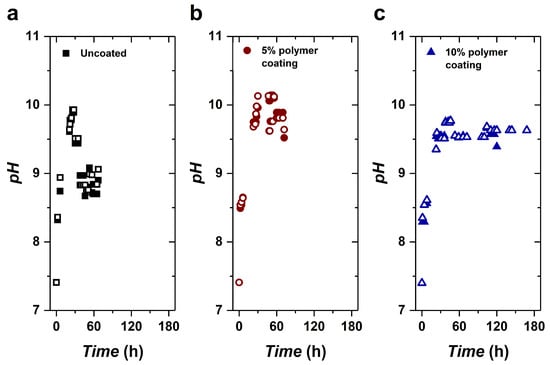
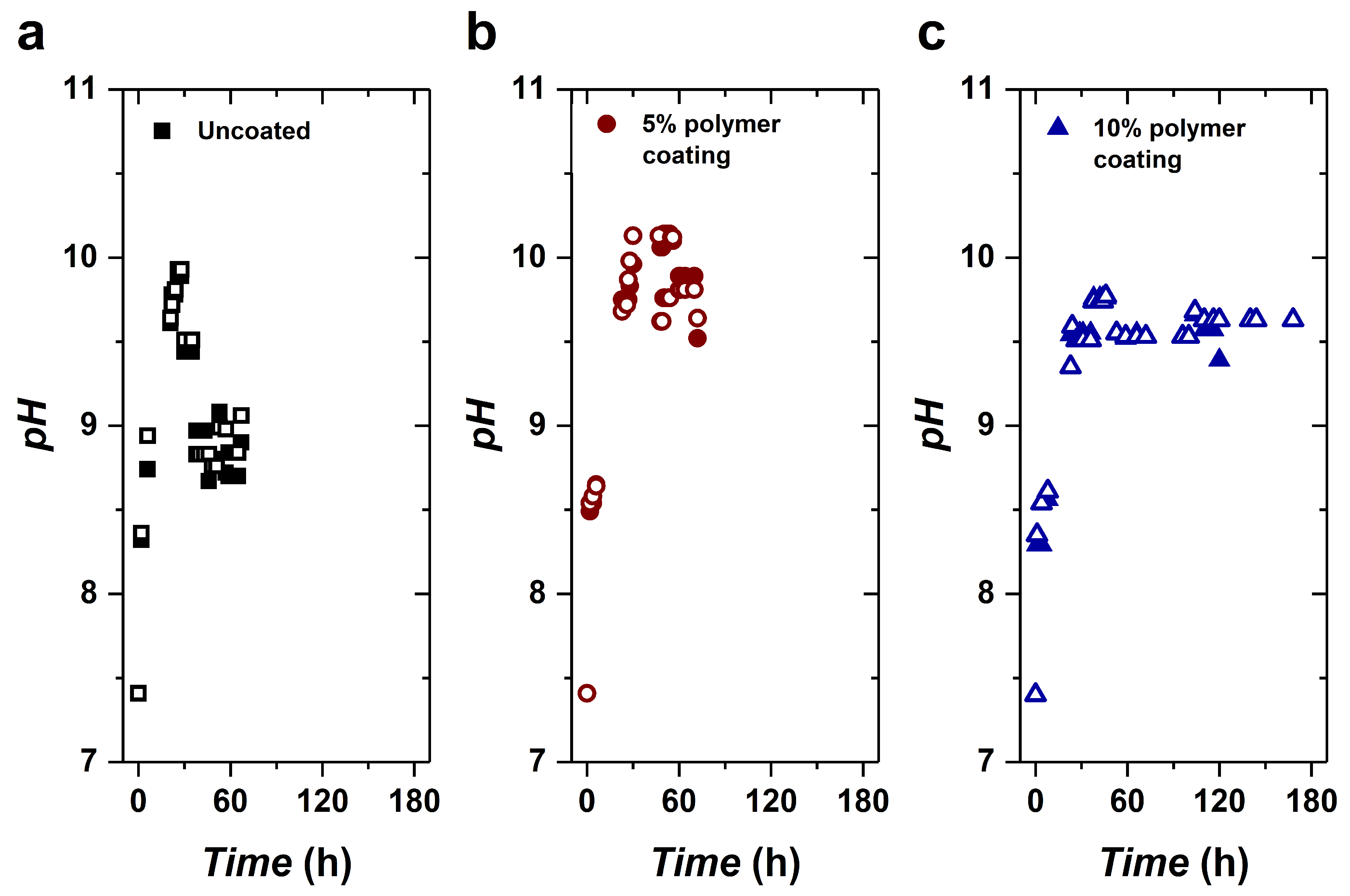
Figure 8 shows the pH during the H2 evolution tests on the three conditions of coating preparation: uncoated (control), 5%, and 10% of PHEMA-g-PCL in the solution. All samples demonstrated a rapid pH increase in the first 30 h, with the uncoated and 5% coating samples showing a greater increase (pH ~ 10) than the 10% coating samples (pH ~ 9.6). The higher pH increase observed under both conditions may be attributed to the corrosion rate, even at the early stages of the experiment, as shown in Figure 6. Further, after the initial increase, the samples showed a decrease in pH (except for the 10% coating samples), reaching a plateau. The constant pH values for each condition are as follows: uncoated (pH ~ 8.8), 5% (pH ~ 9.9) and 10% (pH ~ 9.6) PHEMA-g-PCL coating. Here, it is important to highlight the method chosen for this experiment. The Hawk’s solution was refilled with distilled water to the same volume to maintain the saturated condition (avoiding an increase in salt content after each refill). Therefore, the pH did not decrease during refills.
Figure 8.
Evolution of pH during the immersion experiment of duplicates of the three conditions studied: uncoated samples (a), 5% (b), and 10% (c) PHEMA-g-PCL coated samples. The hollowed points referred to the duplicates of each condition.
The corrosion of magnesium is an electrochemical phenomenon. When immersed in a chloride solution, magnesium undergoes a reaction with water, resulting in the formation of magnesium hydroxide (Mg(OH)2) on the surface and the release of H2 gas. Each Mg atom oxidized to Mg2+ contributes to the production of one hydrogen molecule. Consequently, the volume of H2 generated at a constant pressure and temperature is directly proportional to the mass of oxidized Mg. The overall Mg corrosion reaction may be expressed as follows [32]:
In aqueous environments, chloride ions replace hydroxyl ions on the metal surface, forming the more soluble magnesium chloride (MgCl2). This explains why Mg corrosion occurs more rapidly in biological media and saline solutions, such as the one employed in this study to simulate certain biological conditions. The subsequent reactions summarize the corrosion process in saline solutions:
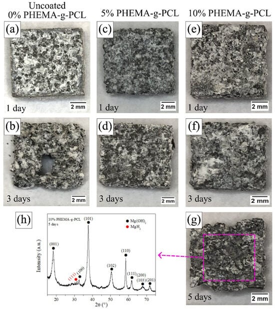
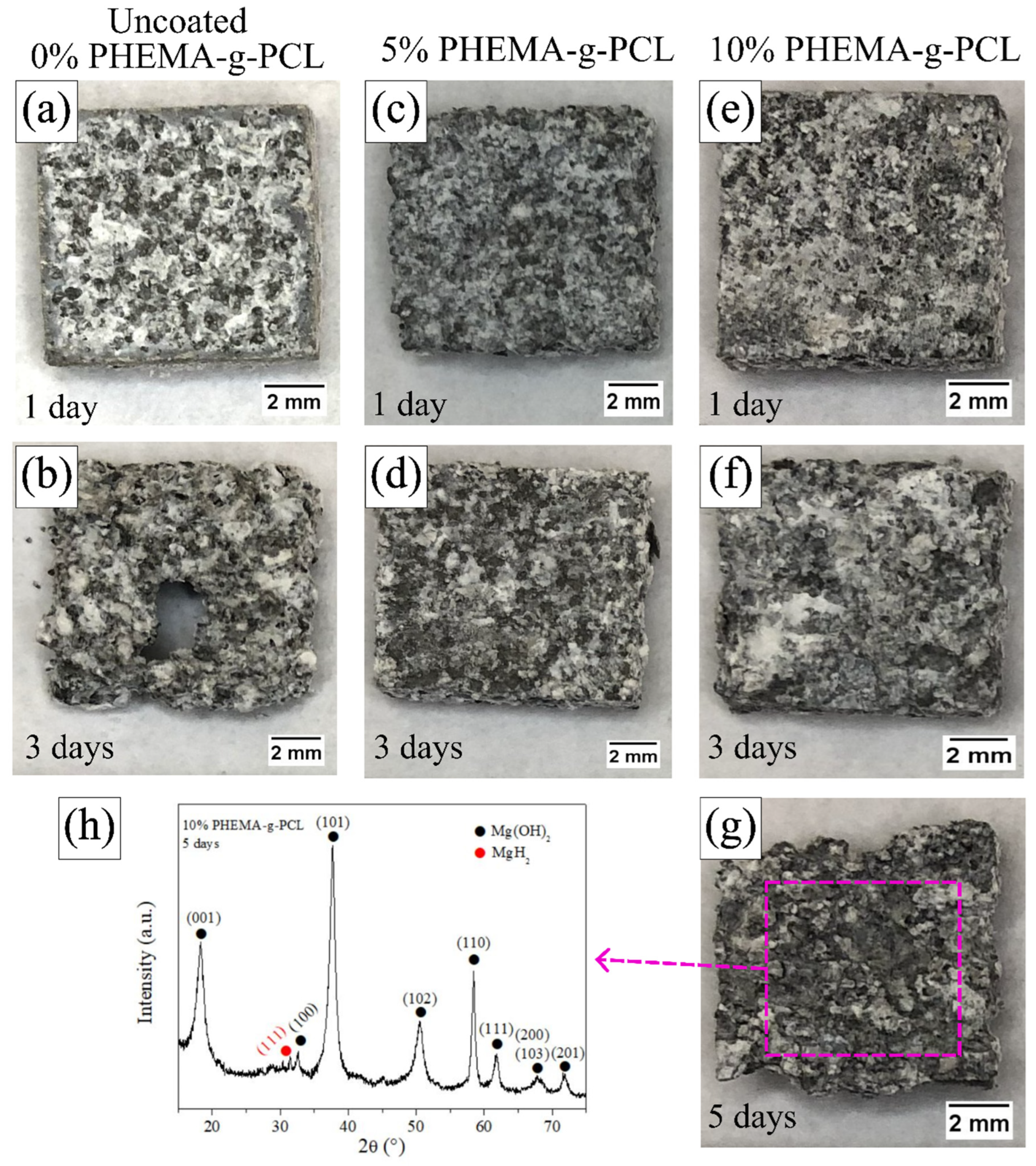
Figure 9 presents macroscopic images obtained after 1, 3, and 5 days of immersion for the uncoated, 5%, and 10% PHEMA-g-PCL coated samples. Despite the higher corrosion rate previously observed in Figure 6, the uncoated sample (Figure 9a) exhibited a more pronounced loss of structural integrity after 1 day compared to the 5% coated sample (Figure 9c). As discussed earlier in Figure 5a,b, the inability of the 5% coating to fully cover the substrate surface may have promoted localized corrosion, explaining the premature loss of shape despite its comparatively lower overall corrosion rate.
Figure 9.
Images of the samples throughout the experiment in the three conditions studied: uncoated (a,b), 5% (c,d), and 10% (e–g) PHEMA-g-PCL coating. XRD data of the corrosion product of the 10% PHEMA-g-PCL sample after 5 days of immersion (h).
After 3 days of immersion, the uncoated sample showed severe degradation, leading to complete perforation (Figure 9b), which highlights the protective effect of the polymer coatings (Figure 9d,f), extending the service life of the alloy. The limited corrosion resistance of the synthesized Mg alloy can be associated with its microstructural features, such as clustered precipitates and fine grain size. Secondary phase particles may act as micro-galvanic couples, serving as preferential corrosion initiation sites [33,34,35]. More recently, Yang et al. demonstrated that corrosion initiated around secondary phase particles [36]. Furthermore, grain refinement increases the total grain boundary area, and the electrochemical activity of grain boundaries, together with crystallographic texture effects, can significantly influence corrosion kinetics in Mg alloys [34,35].
The 10% PHEMA-g-PCL coating exhibited superior performance, maintaining its structural integrity after 1 and 3 days of immersion and remaining intact even after 5 days (Figure 9g), consistent with the electrochemical results previously presented. Notably, the coating at the higher concentration presented homogeneity with no apparent cracks or pores. Therefore, there was an advantage compared to alternative coatings previously reported [37,38,39]. Figure 9h shows the XRD pattern of the corrosion products formed on the 10% coated sample after 5 days of immersion. The predominant corrosion product was Mg(OH)2, as expected for Mg alloys exposed to aqueous environments. Additionally, traces of magnesium hydride (MgH2) were detected. The formation of MgH2 may be associated with the continuous generation and local accumulation of hydrogen during the corrosion process [33].
3. Materials and Methods
3.1. Polymer Synthesis and Characterization
3.1.1. Materials
Hydroxyethyl methacrylate (HEMA—Sigma Aldrich (Burlington, MA, USA), 97%); 2-cyano-2-propyl benzodithioate (Sigma Aldrich, 97%); recrystallized (in cold ethanol) azobisisobutyronitrile (AIBN); distilled under pressure ε-caprolactone (ε-CL); tin II 2-ethylhexanoate (Sigma Aldrich, min. 92.5%); basic alumina (Sigma Aldrich, 99%); ethanol (Synth (Diadema, Brazil), 99.5%); toluene (Sigma Aldrich, 99%); pentane (Sigma Aldrich, 99%); methanol (Sigma Aldrich, 99%); tetrahydrofuran (THF—Sigma Aldrich, 99%); deuterated chloroform (CDCl3—Sigma Aldrich, 99%).
3.1.2. Synthesis of PHEMA-g-PCL
The copolymer was synthesized based on Barner-Kowollik and coworkers’ protocol [26]. Polymerization inhibitors present in HEMA monomer were removed through a basic alumina (Al2O3) column. In a three-neck round-bottom flask, HEMA (0.5 g, 3.84 mmol), ε-CL (4.40 g, 38.55 mmol), 2-cyano-2-propyl benzodithioate (19.3 mg, 0.087 mmol), tin II 2-ethyl-hexanoate (0.8 g, 1.97 mmol), AIBN (4.0 mg, 0.024 mmol), and toluene (2.8 mL) were mixed and then degassed with argon for 30 min under magnetic stirring at 500 rpm. The reaction was carried out under stirring in an oil bath at 100 °C under reflux and an argon atmosphere for 150 min. The oil bath temperature was monitored with a thermometer attached to the stirring plate across the reaction time. Increasing the argon flow rate and purging a glass pipette, 2 drops of the reaction were collected as six aliquots over time (15 min, and every 30 min between 30 min to 150 min of the reaction time). The quenched aliquots were prepared to monitor chain growth via SEC. Further, purification was carried out by precipitation in two consecutive steps: (i) on an excess of pentane and (ii) on an excess of methanol. After each step, the mixture was resolubilized in a minimal amount of THF and precipitated again. The copolymer was characterized by SEC, FTIR, 1H, 13C, and HSQC NMR.
3.1.3. Size Exclusion Chromatography (SEC)
The analysis was carried out on a high-efficiency liquid chromatography Shimadzu (Kyoto, Japan), with an automatic injector (Sil-20A), refraction index detector (RID-A), a pre-column Phenogel 5 µm linear/mixed, and two Phenogel 5 µm 106 Å and 104 Å. The standard samples used were poly(methyl methacrylate) (PMMA). The mobile phase used was THF + 0.3% triethylamine. Samples were prepared in the mobile phase (at a concentration of 4 mg∙mL−1) and filtered through a hydrophobic 0.22 µm polytetrafluoroethylene (PTFE) membrane filter before injection.
3.1.4. Fourier Transformation of Infrared (FTIR) Spectroscopy
A KBr pellet of the purified material was prepared for FTIR spectroscopy analysis on an IR Prestige 21 (Shimadzu, Kyoto, Japan). The corrections, such as the atmosphere’s peak removal, curve smoothing, and baseline adjustment, were made on the software’s equipment.
3.1.5. Nuclear Magnetic Resonance (NMR) Spectroscopy
The 1H, 13C, and heteronuclear single-quantum coherence (HSQC) NMR analyses were carried out on a 400 MHz LC-NMR spectrometer (Bruker, Rheinstetten, Germany). The purified copolymer was prepared in deuterated chloroform (CDCl3). The results were analyzed using the Bruker Topspin 4.1.4 software.
3.2. Alloy Casting and Coating
3.2.1. Materials
Magnesium (Mg) ingot (Dead Sea Magnesium® (Be’er Sheva, Israel), min. 99.97%); yttrium (Y) and gadolinium lumps (Jiayuan Advanced Materials Co. (Ganzhou, China), min. 99.5%); zirconium (Zr) lumps (Shanghai Sheeny Metal Mateirals Co. (Shanghai, China), min. 99.8%); picric acid (Sigma Aldrich, 98%); acetic acid (Synth, 99%); ethanol (Synth, 99.5%); distilled water (distilled in the laboratory); acetone (Synth, 99%); 2-propanol (Synth, 99%); Hank’s solution (Sigma Aldrich); sodium bicarbonate (NaHCO3—ACS (Anapolis, Brazil), 99%).
3.2.2. Alloy Fabrication
A Mg-4.8Y-2.8Gd-0.7Zr wt.% alloy (named as WV43) was produced using high-purity raw materials. The raw materials were melted at 850 °C in a steel crucible using a resistance electric furnace inside a glovebox under argon atmosphere (99.999% min.). The molten alloy was manually stirred for 15 min and then poured into a graphite mold, producing an ingot of dimensions 60 mm × 80 mm × 17 mm. The as-cast ingot was solution heat treated at 525 °C for 12 h under argon flux. The solution treated ingot was pre-heated at 500 °C for 20 min and then hot rolled to produce a plate with thickness of 2.5 mm (85% reduction) after multiple passes. Between the rolling passes, the material was re-heated at 450 °C for 5 min.
3.2.3. Thermodynamic Simulations
Thermodynamic calculations of the alloy were conducted using Thermo-Calc software, employing a database derived from the thermodynamic information of the Mg-Y-Gd [40], Mg-Zr [41], Gd-Zr [42], and Y-Zr [43] systems. A vertical section varying yttrium between 0% and 8% was performed at 2.8 wt.% of gadolinium and 0.7 wt.% of zirconium from the Mg-Gd-Y-Zr database.
3.2.4. Dip Coating Procedure and Analysis
Samples measuring 10 mm × 10 mm × 2.5 mm (surface area of 300 mm2) were sectioned from the plate, and all surfaces were ground using #220 silicon carbide (SiC) paper to standardize the surface roughness. The resulting average roughness (Ra) was 1.21 µm ± 0.47 µm, as measured using a Mitutoyo (Kawasaki, Japan) SJ-210 profilometer.
The samples prior to dip coating procedure were sonicated in acetone and 2-propanol for 10 min and dried. Subsequently, the samples were immersed in the solutions of the copolymer in THF for 5 min and then hot dried for full evaporation of the solvent. The average mass of copolymer coated using 5% solution was 1.3 mg ± 0.5 mg and using 10% was 6.4 mg ± 2.1 mg.
3.2.5. Immersion Test
Immersion tests were conducted on WV43 alloy samples coated with PHEMA-g-PCL at concentrations of 5 wt.% and 10 wt.%, hereafter referred to as the 5% and 10% coatings samples, respectively. Uncoated WV43 samples were used as controls. For each condition, duplicate specimens were evaluated to ensure reproducibility. The corrosion assays were performed using Hank’s solution as the immersion medium. The solution was prepared according to the manufacturer’s instructions by dissolving 9.7 g·L−1 of Hank’s balanced salt mixture and 0.35 g·L−1 of sodium bicarbonate, and the pH was adjusted to 7.40. The tests were conducted in a thermostatically controlled bath at 37 °C. For each sample, the solution was added at a solution-to-surface area ratio of 0.04 mL·mm−2 at a constant volume of 12 mL. The solution pH was monitored using a pHmeter Hanna model Edge with a electrode HI11310, and the volume was refilled with distilled water periodically. The volume of hydrogen gas (H2) evolved during the Mg corrosion reaction was measured using a setup with a submerged and filled burette as followed by the Kirkland, Birbilis, and Staiger report [44].
3.2.6. Scanning Electron Microscopy (SEM) and Light Optical Microscopy (LOM)
Microstructural characterization of the uncoated hot-rolled Mg-Y-Gd-Zr alloy substrate was carried out using a Hitachi (Tokyo, Japan) TM3000 table-top scanning electron microscope in backscattered electron (BSE) mode operating at an accelerating voltage of 15 kV and a working distance (WD) of approximately 9.8 mm. Surface morphology and integrity of the PHEMA-g-PCL polymer coatings were examined using a high-resolution field-emission gun SEM (FEG-SEM, Tescan (Brno, Czech Republic) Mira4) operating in secondary electron (SE) mode at an accelerating voltage of 5 kV, a beam current of 100 pA, and a working distance of approximately 10 mm. Magnifications ranged from 100× to 9000× for alloy microstructure and 2000× to 10,000× for coating surfaces. The grain sizes of the different specimens were determined using light optical microscopy (LOM) (Leica (Wetzlar, Germany) DM4000M) micrographs, applying the line intercept method [45]. The specimens for LOM observations were etched in a solution containing 6 g picric acid, 6 mL acetic acid, 100 mL ethanol, and 10 mL H2O. After the immersion tests, the surface morphology of the samples was examined using LOM. The samples were immersed in the solution for 3 s, then rinsed in isopropyl alcohol and air-dried.
3.2.7. X-Ray Diffraction (XRD)
XRD (PANalytical–Empyrean, Almelo, Netherlands) was performed with Cu-Kα radiation, at 40 kV and 30 mA, 2θ ranging from 20° to 80°, step size of 0.02°, and counting time per step of 150 s. The macrotexture of the hot-rolled alloy specimen was determined by measuring pole figures of {100}, {0002}, {101}, and {102} planes using XRD (PANalytical–Empyrean) with Cu-Kα radiation at 40 kV and 30 mA. The measurements were performed in reflection geometry, with tilt angles (χ) ranging from 0° to 90° and azimuthal angles (φ) from 0° to 360°, both with increments of 5° and counting time of 8.8 s per point. Separate background measurements were performed, and the pole-figure data were analyzed using MTEX software (version 5.8.1) [46,47] in MATLAB 2022b. The corroded surfaces were analyzed through XRD with Cu-Kα radiation, at 40 kV and 30 mA, 2θ ranging from 15° to 75°, step size of 0.02°, and counting time per step of 150 s. The software Highscore was used to analyze the data. The ICSD database for Mg24Y5 Collection Code 642900 was used to identify the phase [48].
4. Conclusions
An enhanced semi-synthetic based on PHEMA-g-PCL was successfully synthesized via simultaneous RAFT and ROP polymerization methodology. Satisfactory control of the polymerization was achieved, yielding a final polymer with a number-average molar mass (Mn) of 63.9 kg mol−1 and an Mw/Mn ratio of 1.21. By NMR analysis, the grafting of the PHEMA fraction was determined to be 92%. Parallelly, a Mg-Gd-Y-Zr alloy was casted and its phases determined. The plates were dip-coated with copolymer solutions at 5 wt.% and 10 wt.%. The coated plates and an uncoated control were assessed in Hank’s solution; the exposure time was increased from 3 days (uncoated) to 7 days (10 wt.% coating) until total plate corrosion. The 10 wt.% coating presented a substantial reduction of the corrosion rate ((0.0045 ± 0.0002) mL·mm−2·h−1) compared to the uncoated plates ((0.0145 ± 0.0009) mL·mm−2·h−1). It was also evidenced that the 5 wt.% coating could reduce the corrosion rate of the plates ((0.0068 ± 0.0029) mL·mm−2·h−1); however, the lack of material on the alloy surface limited the use of the coating for 3 days, despite a clear improvement in the condition of the plate. Further, it was observed that during corrosion, all samples reached a plateau of pH over the experiment time, where the coated samples reached higher values of pH than their uncoated counterparts: uncoated (pH ~ 8.8), 5% (pH ~ 9.9), and 10% (pH ~ 9.6) PHEMA-g-PCL coating. Corrosion products were also identified by XRD as predominant as Mg(OH)2, and traces of MgH2 were also detected. The use of the simultaneous RAFT and ROP polymerization procedure yielded a biopolymer-based polymeric coating that clearly decreased the corrosion rate of Mg alloy. The proof of concept evidences that such polymers should be further explored with structural and size modifications to improve Mg applications in terms of controlled corrosion. For future work, further experiments on mechanical properties of the coating should be explored to advance the proof of concept to an actual application. Further, tests regarding wettability and adhesion should be assessed to investigate topological effects that could improve even more the corrosion rate control.
Supplementary Materials
The following supporting information can be downloaded at https://www.mdpi.com/article/10.3390/inorganics14110292/s1.
Author Contributions
Conceptualization, I.W.F.S., F.H.F., and B.X.d.F.; methodology, I.W.F.S., R.d.S.T., F.H.F., and B.X.d.F.; formal analysis, I.W.F.S., V.d.M.S., V.L.F.d.S., R.d.S.T., and B.X.d.F.; investigation, V.d.M.S., V.L.F.d.S., R.d.S.T., and B.X.d.F.; resources, F.H.F. and C.A.N.; data curation, I.W.F.S.; writing—original draft, I.W.F.S., F.H.F., and B.X.d.F.; writing—review and editing, I.W.F.S., F.H.F., C.A.N., and B.X.d.F.; supervision, F.H.F., C.A.N., and B.X.d.F.; project administration, B.X.d.F.; funding acquisition, F.H.F., C.A.N., and B.X.d.F. All authors have read and agreed to the published version of the manuscript.
Funding
FREITAS: B.X. acknowledges Fundação de Amparo à Pesquisa do Estado de Minas Gerais (FAPEMIG) under grant APQ-00682-24. FHF acknowledges Fundação de Amparo à Pesquisa do Estado de São Paulo (FAPESP) grant 2022/02049-6. This study was financed in part by the Coordenação de Aperfeiçoamento de Pessoal de Nível Superior—Brasil (CAPES)—Finance Code 001.
Institutional Review Board Statement
Not applicable.
Informed Consent Statement
Not applicable.
Data Availability Statement
The original contributions presented in this study are included in the article/supplementary material. Further inquiries can be directed to the corresponding author.
Acknowledgments
The authors acknowledge Antonio Gilberto Ferreira from UFSCAR for the NMR acquisition. The authors acknowledge Layde Teixeira de Carvalho for the assistance in purifying the ε-CL.
Conflicts of Interest
The authors declare no conflicts of interest.
References
- Zheng, Y. Magnesium Alloys as Degradable Biomaterials; Taylor & Francis Group: Oxfordshire, UK, 2016. [Google Scholar]
- Zhang, D.; Peng, F.; Liu, X. Protection of Magnesium Alloys: From Physical Barrier Coating to Smart Self-Healing Coating. J. Alloys Compd. 2021, 853, 157010. [Google Scholar] [CrossRef] [Scilit]
- Atrens, A.; Song, G.-L.; Cao, F.; Shi, Z.; Bowen, P.K. Advances in Mg Corrosion and Research Suggestions. J. Magnes. Alloys 2013, 1, 177–200. [Google Scholar] [CrossRef] [Scilit]
- Jung, H.-D.; Sun Park, H.; Kang, M.-H.; Lee, S.-M.; Kim, H.-E.; Estrin, Y.; Koh, Y.-H. Polyetheretherketone/Magnesium Composite Selectively Coated with Hydroxyapatite for Enhanced in Vitro Bio-Corrosion Resistance and Biocompatibility. Mater. Lett. 2014, 116, 20–22. [Google Scholar] [CrossRef] [Scilit]
- Huang, W.; Mei, D.; Zhang, J.; Chen, D.; Li, J.; Wang, L.; Zhou, Y.; Zhu, S.; Guan, S. Improved Corrosion Resistance and Cytocompatibility of Mg–Zn–Y–Nd Alloy by the Electrografted Polycaprolactone Coating. Colloids Surf. A Physicochem. Eng. Asp. 2021, 629, 127471. [Google Scholar] [CrossRef] [Scilit]
- Ding, Y.; Wen, C.; Hodgson, P.; Li, Y. Effects of Alloying Elements on the Corrosion Behavior and Biocompatibility of Biodegradable Magnesium Alloys: A Review. J. Mater. Chem. B 2014, 2, 1912–1933. [Google Scholar] [CrossRef] [Scilit] [PubMed]
- Zeng, R.-C.; Qi, W.-C.; Cui, H.-Z.; Zhang, F.; Li, S.-Q.; Han, E.-H. In Vitro Corrosion of As-Extruded Mg–Ca Alloys—The Influence of Ca Concentration. Corros. Sci. 2015, 96, 23–31. [Google Scholar] [CrossRef] [Scilit]
- Chen, J.; Song, Y.; Shan, D.; Han, E.-H. Modifications of the Hydrotalcite Film on AZ31 Mg Alloy by Phytic Acid: The Effects on Morphology, Composition and Corrosion Resistance. Corros. Sci. 2013, 74, 130–138. [Google Scholar] [CrossRef] [Scilit]
- Cui, L.-Y.; Gao, S.-D.; Li, P.-P.; Zeng, R.-C.; Zhang, F.; Li, S.-Q.; Han, E.-H. Corrosion Resistance of a Self-Healing Micro-Arc Oxidation/Polymethyltrimethoxysilane Composite Coating on Magnesium Alloy AZ31. Corros. Sci. 2017, 118, 84–95. [Google Scholar] [CrossRef] [Scilit]
- Li, L.-Y.; Cui, L.-Y.; Zeng, R.-C.; Li, S.-Q.; Chen, X.-B.; Zheng, Y.; Kannan, M.B. Advances in Functionalized Polymer Coatings on Biodegradable Magnesium Alloys—A Review. Acta Biomater. 2018, 79, 23–36. [Google Scholar] [CrossRef] [Scilit] [PubMed]
- Yin, Z.-Z.; Qi, W.-C.; Zeng, R.-C.; Chen, X.-B.; Gu, C.-D.; Guan, S.-K.; Zheng, Y.-F. Advances in Coatings on Biodegradable Magnesium Alloys. J. Magnes. Alloys 2020, 8, 42–65. [Google Scholar] [CrossRef] [Scilit]
- Yang, J.; Wang, D.; Wang, J.; Hu, W. Corrosion Resistance and Near-Infrared Light Induced Self-Healing Behavior of Polycaprolactone Coating with MIL-53@TA on Magnesium Alloy. Appl. Surf. Sci. 2022, 585, 152729. [Google Scholar] [CrossRef] [Scilit]
- Xu, L.; Yamamoto, A. Characteristics and Cytocompatibility of Biodegradable Polymer Film on Magnesium by Spin Coating. Colloids Surf. B Biointerfaces 2012, 93, 67–74. [Google Scholar] [CrossRef] [Scilit] [PubMed]
- Bedair, T.M.; Yu, S.J.; Im, S.G.; Park, B.J.; Joung, Y.K.; Han, D.K. Effects of Interfacial Layer Wettability and Thickness on the Coating Morphology and Sirolimus Release for Drug-Eluting Stent. J. Colloid Interface Sci. 2015, 460, 189–199. [Google Scholar] [CrossRef] [Scilit] [PubMed]
- Matyjaszewski, K.; Xia, J. Atom Transfer Radical Polymerization. Chem. Rev. 2001, 101, 2921–2990. [Google Scholar] [CrossRef] [Scilit] [PubMed]
- Moad, G.; Rizzardo, E.; Thang, S.H. Radical Addition–Fragmentation Chemistry in Polymer Synthesis. Polymer 2008, 49, 1079–1131. [Google Scholar] [CrossRef] [Scilit]
- Perrier, S. 50th Anniversary Perspective: RAFT Polymerization—A User Guide. Macromolecules 2017, 50, 7433–7447. [Google Scholar] [CrossRef] [Scilit]
- Jafari, V.F.; Grace, J.L.; Li, J.; Tanaka, J.; Jones, G.R.; Anastasaki, A.; You, W.; Zhu, J.; Kamigaito, M.; Boyer, C.; et al. Beyond Traditional RAFT Polymerization: Emerging Strategies and Future Perspectives; A Third Update. Adv. Sci. 2026, 13, e20657. [Google Scholar] [CrossRef] [Scilit] [PubMed]
- Albertsson, A.-C.; Varma, I.K. Recent Developments in Ring Opening Polymerization of Lactones for Biomedical Applications. Biomacromolecules 2003, 4, 1466–1486. [Google Scholar] [CrossRef] [Scilit] [PubMed]
- Woodruff, M.A.; Hutmacher, D.W. The Return of a Forgotten Polymer—Polycaprolactone in the 21st Century. Prog. Polym. Sci. 2010, 35, 1217–1256. [Google Scholar] [CrossRef] [Scilit]
- Danhier, F.; Ansorena, E.; Silva, J.M.; Coco, R.; Le Breton, A.; Préat, V. PLGA-Based Nanoparticles: An Overview of Biomedical Applications. J. Control. Release 2012, 161, 505–522. [Google Scholar] [CrossRef] [Scilit] [PubMed]
- Chhipa, S.M.; Sharma, S.; Kumar Bagha, A. Recent Development in Polymer Coating to Prevent Corrosion in Metals: A Review. Mater. Today Proc. 2024, S2214785324004851. [Google Scholar] [CrossRef] [Scilit]
- Moaref, R.; Shahini, M.H.; Eivaz Mohammadloo, H.; Ramezanzadeh, B.; Yazdani, S. Application of Sustainable Polymers for Reinforcing Bio-Corrosion Protection of Magnesium Implants—A Review. Sustain. Chem. Pharm. 2022, 29, 100780. [Google Scholar] [CrossRef] [Scilit]
- da Silva, V.L.F.; de Freitas, B.X.; Cury, P.L.C.; Teixeira, R.d.S.; Tomachuk, C.R.; Coelho, G.C.; Nunes, C.A. Effect of Thermomechanical Processing and Aging on the Microstructure and Mechanical Properties of Mg-4.8Y-2.8Gd-0.7Zr (wt.%) Alloy. J. Mater. Eng. Perform. 2026, 35, 32453–32464. [Google Scholar] [CrossRef] [Scilit]
- Ferraz, F.M.B.; de Freitas, B.X.; Cury, P.L.C.T.; da Silva, V.L.F.; Nunes, C.Â.; Tomachuk, C.R. Effect of Solution Heat-Treatment and Aging on the Corrosion Behavior and Microstructure of Biodegradable Mg–Y–Gd–Zr Alloys. Mater. Res. 2026, 29, e20250713. [Google Scholar] [CrossRef] [Scilit]
- Le Hellaye, M.; Lefay, C.; Davis, T.P.; Stenzel, M.H.; Barner-Kowollik, C. Simultaneous Reversible Addition Fragmentation Chain Transfer and Ring-Opening Polymerization. J. Polym. Sci. A Polym. Chem. 2008, 46, 3058–3067. [Google Scholar] [CrossRef] [Scilit]
- Yu, X.; Jiang, B.; Yang, H.; Yang, Q.; Xia, X.; Pan, F. High Temperature Oxidation Behavior of Mg-Y-Sn, Mg-Y, Mg-Sn Alloys and Its Effect on Corrosion Property. Appl. Surf. Sci. 2015, 353, 1013–1022. [Google Scholar] [CrossRef] [Scilit]
- Milkereit, B.; Burgschat, L.; Kemsies, R.H.; Springer, A.; Schick, C.; Kessler, O. In Situ Differential Scanning Calorimetry Analysis of Dissolution and Precipitation Kinetics in Mg–Y–RE Alloy WE43. J. Magnes. Alloys 2019, 7, 1–14. [Google Scholar] [CrossRef] [Scilit]
- Yang, L.; Huang, Y.; Hou, Z.; Xiao, L.; Xu, Y.; Dong, X.; Li, F.; Kurz, G.; Sun, B.; Li, Z.; et al. Microstructure, Mechanical Properties and Fracture Behaviors of Large-Scale Sand-Cast Mg-3Y-2Gd-1Nd-0.4Zr Alloy. J. Magnes. Alloys 2023, 11, 2763–2775. [Google Scholar] [CrossRef] [Scilit]
- Yang, H.; Gao, Y.; Qin, W.; Sun, J.; Huang, Z.; Li, Y.; Li, B.; Sun, J. A Robust Superhydrophobic Surface on AA3003 Aluminum Alloy with Intermetallic Phases in-Situ Pinning Effect for Corrosion Protection. J. Alloys Compd. 2022, 898, 163038. [Google Scholar] [CrossRef] [Scilit]
- Yang, H.; Dong, Y.; Li, X.; He, W.; Liu, Y.; Mu, X.; Zhao, Y.; Wang, X.; Yang, F.; Fu, W.; et al. Enhancing Tribological Performance of AA3003 Aluminum Alloy via Adjusting Surface Wettability: Synergistic Effects of Chemical Etching and Modification. Colloids Surf. A Physicochem. Eng. Asp. 2024, 696, 134330. [Google Scholar] [CrossRef] [Scilit]
- Ascencio, M.; Pekguleryuz, M.; Omanovic, S. An Investigation of the Corrosion Mechanisms of WE43 Mg Alloy in a Modified Simulated Body Fluid Solution: The Influence of Immersion Time. Corros. Sci. 2014, 87, 489–503. [Google Scholar] [CrossRef] [Scilit]
- Song, G.; Atrens, A. Understanding Magnesium Corrosion—A Framework for Improved Alloy Performance. Adv. Eng. Mater. 2003, 5, 837–858. [Google Scholar] [CrossRef] [Scilit]
- Birbilis, N.; Easton, M.A.; Sudholz, A.D.; Zhu, S.M.; Gibson, M.A. On the Corrosion of Binary Magnesium-Rare Earth Alloys. Corros. Sci. 2009, 51, 683–689. [Google Scholar] [CrossRef] [Scilit]
- Gusieva, K.; Davies, C.H.J.; Scully, J.R.; Birbilis, N. Corrosion of Magnesium Alloys: The Role of Alloying. Int. Mater. Rev. 2015, 60, 169–194. [Google Scholar] [CrossRef] [Scilit]
- Yang, F.; Yang, H.; Fu, W.; Li, X.; Gao, Y.; Qiao, Z.; Zhuo, Z. Corrosion and Discharge Mechanism of Mg-Ga-Hg Anode for Magnesium-Air Batteries. J. Power Sources 2026, 677, 240001. [Google Scholar] [CrossRef] [Scilit]
- Yavuzyegit, B.; Karali, K.; Davis, S.; Morrison, B.; Karabal, S.; Balandiz, K.; Smith, N.; Usov, S.; Shashkov, P.; Bonithon, R.; et al. High-Resolution DIC Analysis of In Situ Strain and Crack Propagation in Coated AZ31 Magnesium Alloys under Mechanical Loading. J. Mater. Sci. 2025, 60, 14708–14730. [Google Scholar] [CrossRef] [Scilit] [PubMed]
- Bakhsheshi-Rad, H.R.; Hamzah, E.; Ying, W.S.; Razzaghi, M.; Sharif, S.; Ismail, A.F.; Berto, F. Improved Bacteriostatic and Anticorrosion Effects of Polycaprolactone/Chitosan Coated Magnesium via Incorporation of Zinc Oxide. Materials 2021, 14, 1930. [Google Scholar] [CrossRef] [Scilit] [PubMed]
- Nicolao-Gómez, A.; Martínez-Campos, E.; Moreno, L.; Rodríguez-Hernández, J.; Matykina, E. Hierarchical Hybrid Coatings with Drug-Eluting Capacity for Mg Alloy Biomaterials. Materials 2023, 16, 7688. [Google Scholar] [CrossRef] [Scilit] [PubMed]
- Guo, C.; Du, Z.; Li, C. A Thermodynamic Description of the Gd–Mg–Y System. Calphad 2007, 31, 75–88. [Google Scholar] [CrossRef] [Scilit]
- Arroyave, R.; Shin, D.; Liu, Z.K. Modification of the Thermodynamic Model for the Mg-Zr System. Calphad Comput. Coupling Phase Diagr. Thermochem. 2005, 29, 230–238. [Google Scholar] [CrossRef] [Scilit]
- Bo, H.; Liu, L.B.; Hu, J.L.; Zhang, X.D.; Jin, Z.P. Thermodynamic Re-Assessment of the Al-Gd and Gd-Zr Systems. Thermochim. Acta 2014, 591, 51–56. [Google Scholar] [CrossRef] [Scilit]
- He, X.C.; Liu, H.S. Determination of the Isothermal Section of the Cu-Zr-Y Ternary System at 978 K. J. Alloys Compd. 2009, 475, 245–251. [Google Scholar] [CrossRef] [Scilit]
- Kirkland, N.T.; Birbilis, N.; Staiger, M.P. Assessing the Corrosion of Biodegradable Magnesium Implants: A Critical Review of Current Methodologies and Their Limitations. Acta Biomater. 2012, 8, 925–936. [Google Scholar] [CrossRef] [Scilit] [PubMed]
- de Freitas, B.X.; Antonini, L.A.; Cury, P.L.C.T.; da Silva, V.L.F.; Chaia, N.; Tomachuk, C.R.; Mathieu, S.; Coelho, G.C.; dos Santos, C.; Nunes, C.A. Microstructural Evolution and Electrochemical Behavior of Solution Treated, Hot Rolled and Aged MgDyZnZr Alloy. Metals 2021, 11, 1855. [Google Scholar] [CrossRef] [Scilit]
- Bachmann, F.; Hielscher, R.; Schaeben, H. Texture Analysis with MTEX—Free and Open Source Software Toolbox. Solid State Phenom. 2010, 160, 63–68. [Google Scholar] [CrossRef] [Scilit]
- Hielscher, R.; Schaeben, H. A Novel Pole Figure Inversion Method: Specification of the MTEX Algorithm. J. Appl. Crystallogr. 2008, 41, 1024–1037. [Google Scholar] [CrossRef] [Scilit]
- Kost, M.E.; Kuznetsov, N.T.; Shilov, A.L. New Hydride Phases in the Systems R-Mg-H (R = Y, La, Ce). Dokl. Akad. Nauk SSSR 1987, 292, 632–634. [Google Scholar]
Disclaimer/Publisher’s Note: The statements, opinions and data contained in all publications are solely those of the individual author(s) and contributor(s) and not of MDPI and/or the editor(s). MDPI and/or the editor(s) disclaim responsibility for any injury to people or property resulting from any ideas, methods, instructions or products referred to in the content. |
© 2026 by the authors. Licensee MDPI, Basel, Switzerland. This article is an open access article distributed under the terms and conditions of the Creative Commons Attribution (CC BY) license.