


Abstract
We present a nanovoid-assisted ring-core fiber designed for low-bending-loss few-mode transmission. We develop a 3D model that accounts for stress-induced perturbation in bending-loss evaluation. Our model yields closer agreement with published experimental data compared to conventional conformal mapping. The nanovoid ring-core fiber reduces the bending loss of higher-order modes by up to three orders of magnitude, and improves the degeneracy of the higher-order pair nearly ten-fold at tight bending radii. The proposed fiber maintains the same intermodal separation compared to the reference ring-core fiber across all investigated radii.
1. Introduction
The rapid growth of cloud computing, video streaming, and artificial intelligence is driving a continuous increase in global data traffic, creating a demand for higher-capacity optical communication systems. Space-division multiplexing (SDM) using few-mode fibers (FMFs) has emerged as a promising approach to increase transmission capacity by enabling multiple spatial channels within a single optical fiber. In particular, ring-core fibers (RCFs) supporting orbital angular momentum (OAM) modes are highly promising due to their high channel density and low inter-modal crosstalk [1,2]. For practical deployment, however, RCFs must maintain low levels of bending loss under the tight routing conditions commonly encountered in data centers and access networks.
RCFs have demonstrated significantly better bending performance than conventional single-mode fibers (SMFs). At a bend radius of approximately 5 mm, experimental results show that the fundamental mode of RCFs exhibits negligible bending loss, typically below 0.01 dB/turn [3,4], and reaches 2.4 dB/turn for the highest-order mode at the same bending radius [3]. Numerical studies often report extremely low bending-loss values approaching 10−10 dB/turn, even at a bending radius of 2 mm [5]. These values are maintained at a very low level, even in the case of higher-order modes [6,7,8]. However, due to bending-induced birefringence and symmetry breaking, OAM mode purity degrades, and higher-order modes are cut off [5,8]. As a result, the performance of RCFs is limited not only by loss, but also by the degradation of modal integrity; the minimum usable bend radius is determined by both effects.
These observations highlight two key challenges. First, there is a significant discrepancy between experimental and numerical bending-loss results in RCFs, particularly as most numerical models only evaluate confinement loss. The most widely used approach is conformal mapping [9], which transforms a bent fiber into an equivalent straight fiber with a modified refractive-index distribution. This method neglects mechanical stress induced by bending. Through the photoelastic effect, this stress modifies the refractive index and contributes to the total bending loss. Other approaches to modeling fiber bending loss include analytical methods based on ray optics and power-flow modeling [10], as well as studies that consider thermal effects on bend-induced loss [11].
Second, higher-order mode groups exhibit higher bending sensitivity, and require novel fiber designs. Trench-assisted fibers [12,13], hole-assisted fibers [14,15,16], and nanostructured claddings [17,18] have been widely used to reduce bending loss in single-mode and few-mode fibers [19,20,21]. Among these, nanovoid-engineered claddings have shown ultra-low bending-loss values due to simultaneous optical confinement enhancement and effective mechanical modification of the fiber structure [17,18]. However, to our knowledge, their application to RCFs has not yet been explored.
In this work, we address both challenges. First, we develop a fully coupled mechanical–optical bending model that considers stress-optic and geometric contributions to bending loss at room temperature. A three-dimensional mechanical solver is used to compute bending-induced stress, which is mapped to a refractive-index perturbation into an optical model. This framework captures leakage due to geometric bending and mechanical stress, enabling improved prediction of bending loss for all guided modes. Second, we propose a nanovoid ring-core fiber (NV-RCF) incorporating an annular nanovoid silica layer in the cladding. Its effective optical and mechanical properties are derived from unit-cell simulations, and its bending performance is evaluated through parametric analysis relative to a reference RCF.
2. Materials and Methods
2.1. Bending Model and Validation
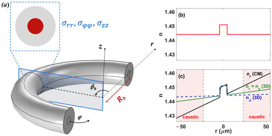
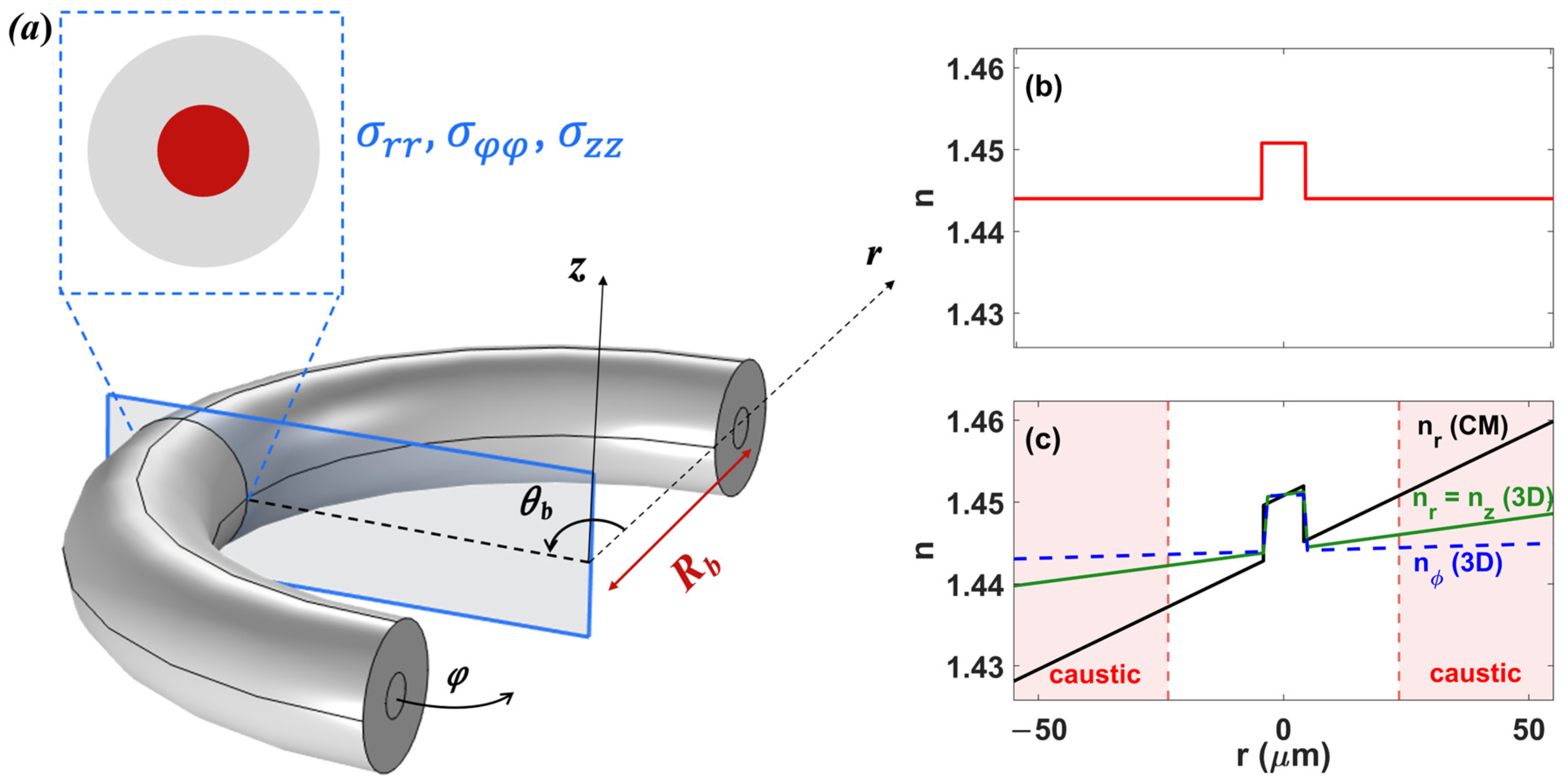
To accurately evaluate the loss α of a bent optical fiber, as shown in Figure 1a, two distinct phenomena must be considered: the radiative loss caused by the geometric curvature of the fiber, and the loss caused by the stress-induced modification of the refractive-index profile. The most widely used approach for calculating α is the conformal mapping transformation following the equation , where r is the transverse coordinate and Rb is the bend radius [9]. The resulting index profile is shown in Figure 1c. In contrast to the straight fiber index in Figure 1b, the conformal mapping transformation introduces a significant tilting across the fiber cross-section. To include stress effect, an empirical elasto-optic correction is typically used by substituting Rb with an effective bend radius Reff ≈ 1.28Rb for silica fibers [22]. Another approach is to use geometrically exact beam theory (GEBT) to calculate the bending-induced strain tensor [23].
Figure 1.
(a) Illustration of an optical fiber bend. Index profile of a (b) straight fiber and a (c) bent fiber at Rb = 5 mm with the conformal mapping from our proposed 3D model.
In this work, we propose a 3D bending model that calculates mechanical stress. The optical fiber is modeled as a composite cylinder comprising a silica cladding and a GeO2-doped core. A prescribed displacement is applied in the solid mechanics module of COMSOL Multiphysics 6.0 to induce an actual bend of the optical fiber with a radius Rb; moreover, the normal stress components σrr, σφφ, and σzz are sampled at the mid-span cross-section (θb = π/2) to avoid boundary artifacts. The stress distribution is converted to refractive-index perturbation via the stress-optic law [24]:
where C1 = 0.69 × 10⁻¹² Pa−1, C2 = 4.19 × 10⁻¹² Pa−1 are the stress-optic coefficients, and n is the isotropic refractive index of the unstressed fused silica glass material. The resulting anisotropic index profile is shown alongside the conformal mapping profile in Figure 1c.
The three index components are incorporated as an anisotropic permittivity tensor into the optical model solver. A perfectly matched layer (PML) is applied at the outer boundary of the computational domain to absorb radiated fields and suppress unphysical reflections. The resulting complex effective index is used to evaluate the bending loss per turn, as follows:
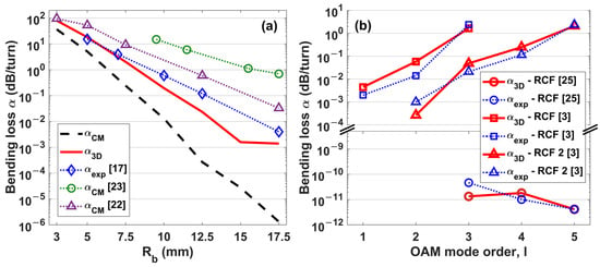
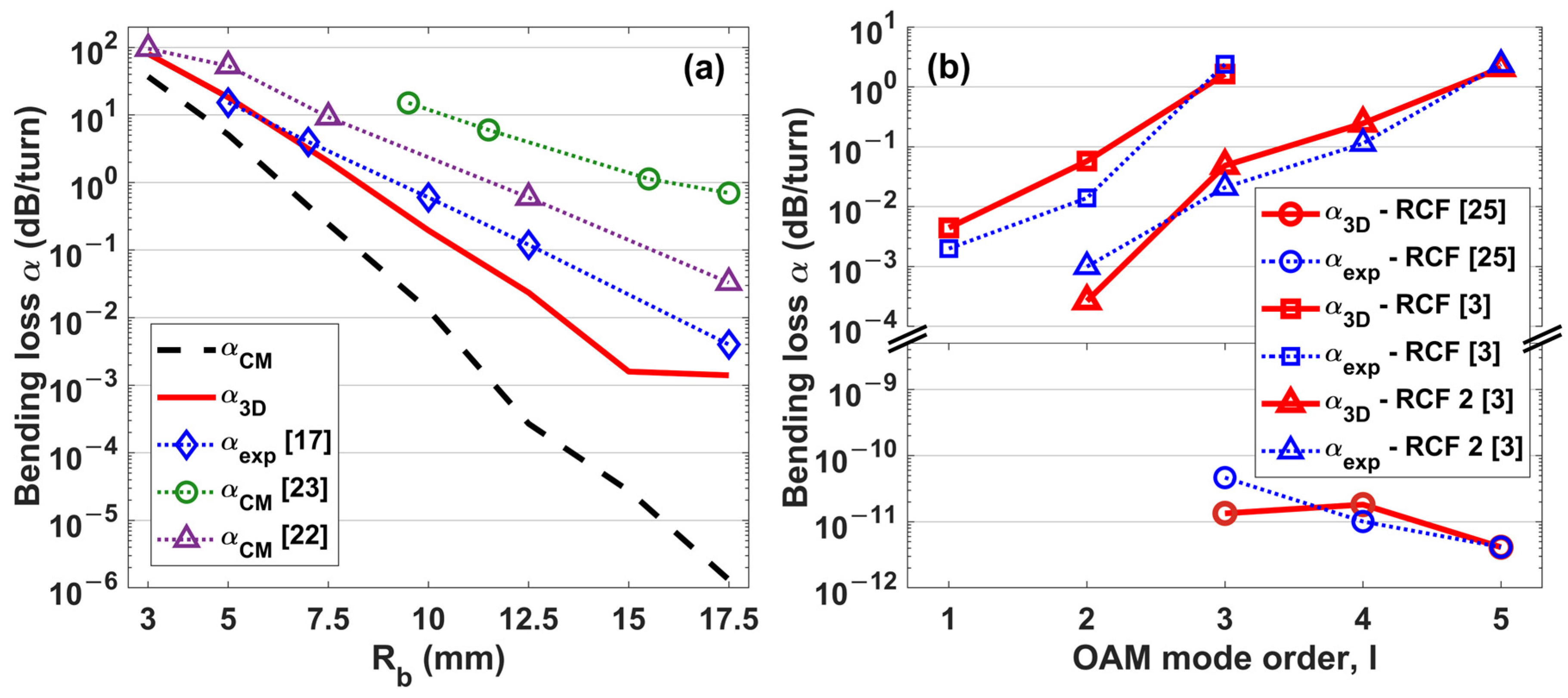
Figure 2a,b present the bending loss of SMF-28 and three different RCFs at 1550 nm, respectively, calculated using different approaches mentioned in the previous section. The results are compared with published numerical [22,23] and experimental [3,17,25] data. For SMF-28, αCM underestimates bending loss at large bend radii. At a 5 mm bend radius, αCM predicts a loss of approximately 5 dB/turn, which is nearly three-fold lower than the experimentally measured value of about 15 dB/turn [17]. We also observe that the previously reported corrected models [22,23] tend to overestimate the loss over a wide range of bend radii.
Figure 2.
Bending loss α (a) as a function of bend radius Rb for SMF-28 [17, 22, 23], and (b) as a function of OAM mode order l for three reference ring-core fibers: RCF [25] at Rb = 10 mm, and RCF [3] and RCF2 [3] at Rb = 4.4 mm.
Our proposed model demonstrates more accurate prediction and achieves a high-fidelity correlation with experimental data across the entire Rb range. At a 5 mm bend radius, α3D predicts 18 dB/turn, closely matching the experimental value. A similar trend is observed for three different RCFs [3,25], as shown in Figure 2b: Rb = 10 mm for RCF [25], and Rb = 4.4 mm for RCFs [3] for different OAM mode orders l. The results for α3D closely match and are within a physically reasonable range with the experimentally reported data for all three fibers. This further supports the validity of our approach beyond its application to SMF-28. An additional limitation of the conformal mapping approach arises under tight bending conditions. The linearly increasing equivalent index profile eventually exceeds the core refractive index beyond a critical boundary known as the radiation caustic [22]. Beyond this boundary, the modal field transitions from evanescent to oscillatory, requiring an artificial truncation of the computational domain that introduces significant error as the bend radius decreases. In contrast, our model formulates propagation directly along the azimuthal direction of the true bent geometry, resulting in an index profile that remains physically realistic. Figure 1c compares the two index profiles. The conformal mapping profile increases unphysically with r, whereas the profile obtained with our 3D model remains bounded. For this reason, the proposed model is adopted throughout this work for the design and optimization of the NV-RCF.
2.2. Nanovoid Ring-Core Fiber Design (NV-RCF)
The proposed nanovoid ring-core fiber (NV-RCF) is based on a previously reported OAM stable RCF design. This fiber supports 10 vector modes; thus, the propagation of the OAM±1,1 and OAM±2,1 mode groups follows the equations below:
where l is the topological charge of the OAM mode.
The geometry of the NV-RCF is derived from RCF #4, presented in [26]. The geometrical and optical parameters of the baseline RCF are summarized in Table 1.
Table 1.
RCF parameters.
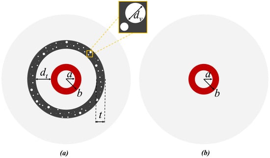
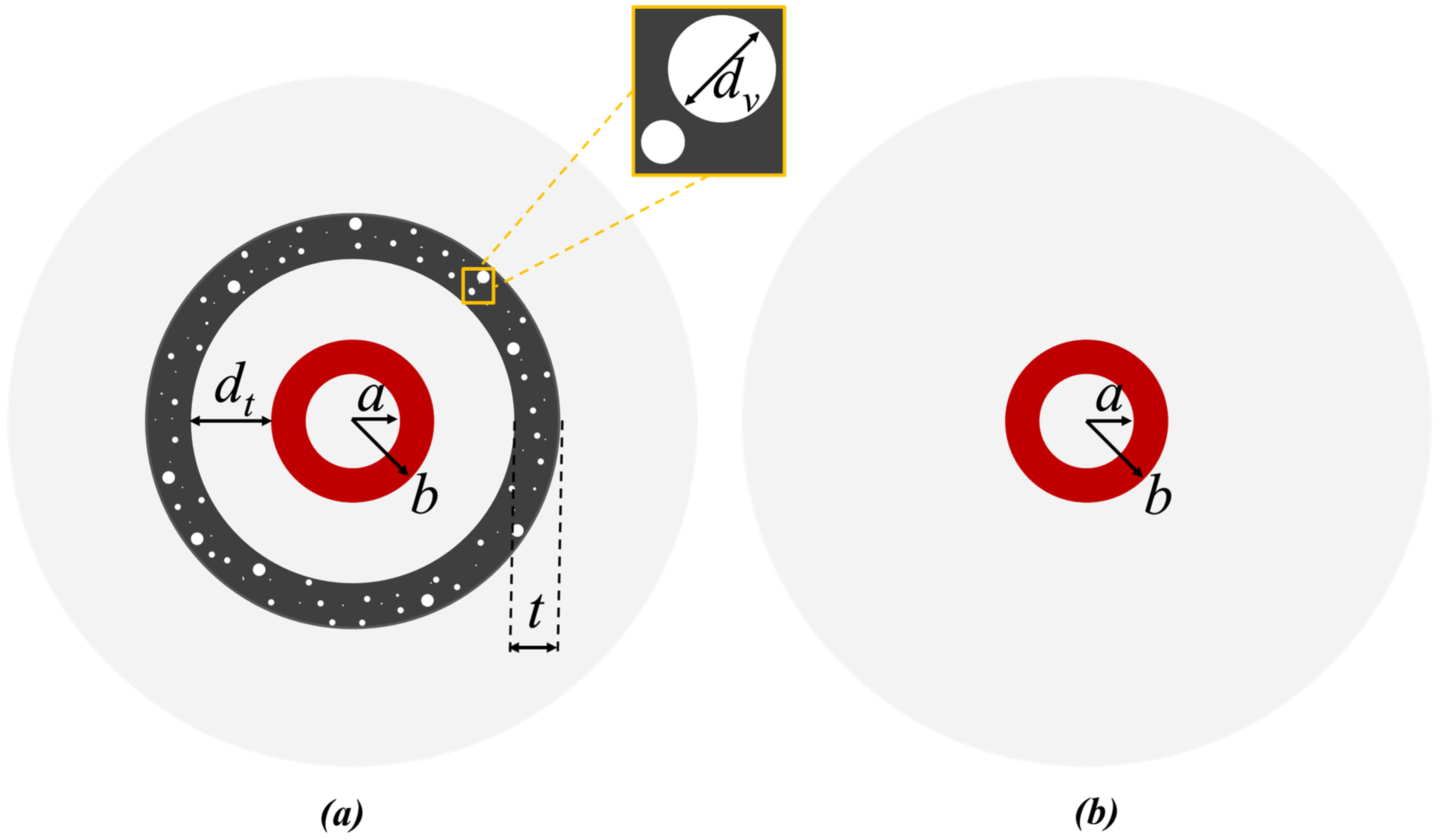
Figure 3 illustrates cross-sections of the NV-RCF and the reference RCF. In the NV-RCF, a nanovoid silica layer forms an annular ring positioned at a distance dt from the outer ring-core and has a thickness t. This additional layer provides a new degree of freedom to tailor optical confinement and reduces bending-induced loss.
Figure 3.
Cross-sections of the (a) NV-RCF and (b) reference RCF [26].
The nanovoid layer can be fabricated using two methods based on the outside vapor deposition (OVD) [17,18], or by using silica powder with gas-producing powders (GPP) [27]. In the OVD-based approach, nanovoids are formed by trapping low-permeability gases during the consolidation of silica soot. In the second approach, GPP generates nanovoids in situ during the high-temperature drawing stage. In both methods, the final morphology of the voids, size, density, and distribution is governed by processing parameters such as gas type and diffusivity, sintering conditions, and drawing tension.
At 1550 nm, the refractive index of fused silica cladding is n2 = 1.444. The ring-core consists of silica doped with m = 19 mol % GeO2, resulting in a refractive index of n1 = 1.474. The Young’s modulus, Poisson’s ratio, and density of the Ge-doped silica are estimated using the empirical relations reported in [28]. The material parameters used in this work are summarized in Table 2.
Table 2.
NV-RCF core and cladding material parameters.
Nanovoid Silica as an Effective Material
The nanovoid silica layer is modeled as a homogeneous effective medium consisting of fused silica and randomly distributed spherical air voids. The void diameters dv follow a normal statistical distribution ranging from 10 nm to 350 nm, with a mean diameter of approximately 150 nm and a standard deviation of approximately 65 nm, a composition that is consistent with SEM image analysis of a fabricated nanovoid-trench silica fiber [18]. The full derivation of the effective optical and mechanical properties for the void fraction f ranging from 0% to 5% is provided in Appendix A, and the key results are summarized below.
The effective refractive index nnv(f) decreases monotonically with increasing void fractions, since silica is progressively replaced by air. The effective index contrast between the nanovoid layer and the silica cladding is defined as , and increases from approximately 0.002 at f = 0.5% to 0.028 at f = 5%. The effective Young’s modulus Env and effective density ρnv of the nanovoid layer decrease by 4% and 5%, respectively, as f increases from 0.5% to 5%. Poisson’s ratio remains relatively constant. These values are implemented into the 3D structural mechanics model described in Section 2.1 to evaluate mechanical stress and bending loss.
3. Results and Discussion
We evaluate the bending performance of the proposed NV-RCF at a bending radius of 5 mm and an λ = 1550 nm operating wavelength using the 3D bending model described in Section 2.1. The bending performance of the NV-RCF is evaluated through a parametric sweep of the nanovoid ring thickness t, the radial distance from the outer core dt, and the void fraction f.
3.1. Influence of the Nanovoid Ring Thickness t and Distance dt, for f = 2.5%
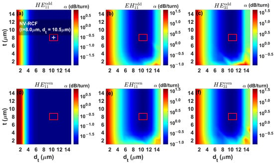
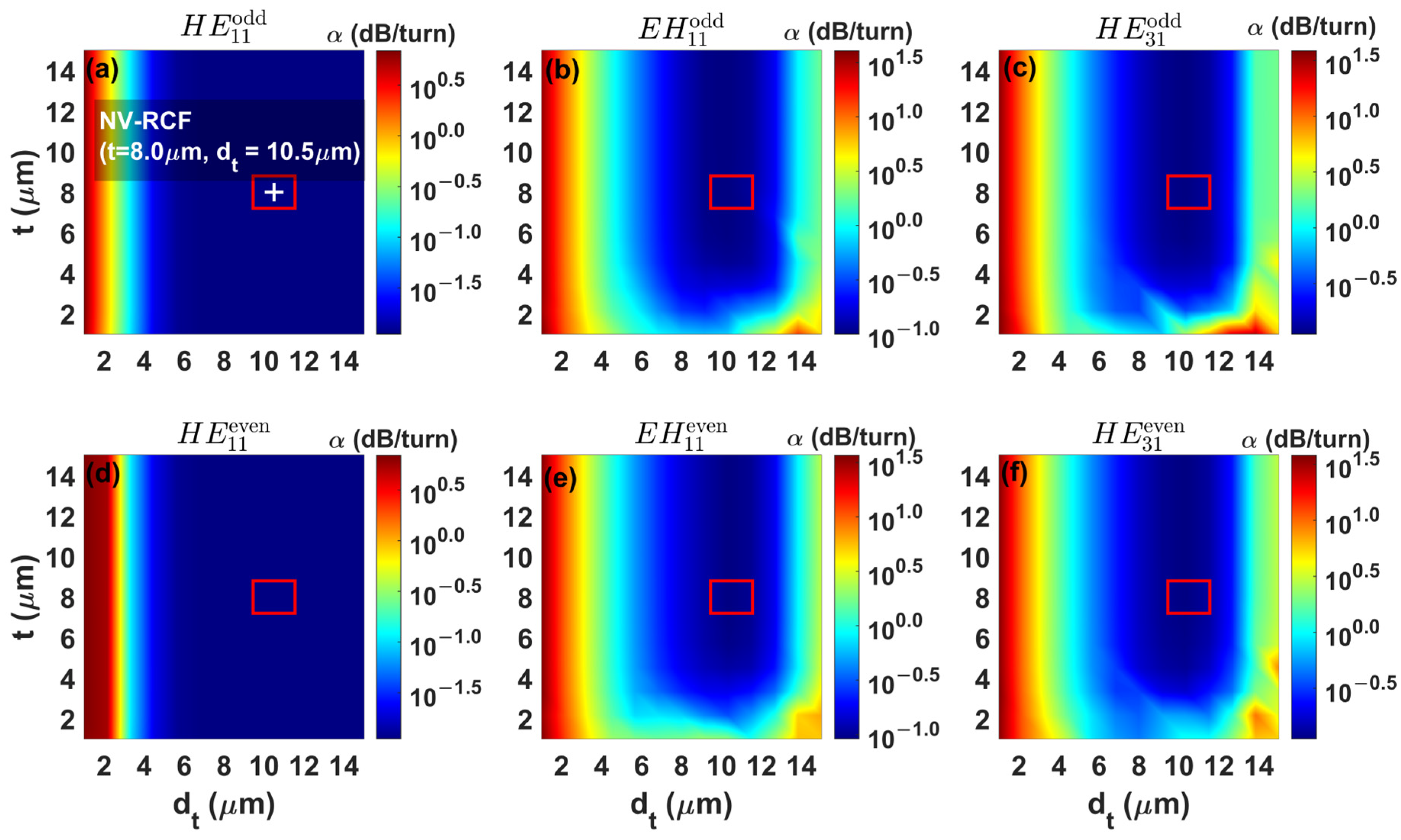
We first investigate the influence of t and dt on bending loss at a fixed void fraction of 2.5%. The bending loss α (dB/turn) as a function of t and dt for the modes , , , and is displayed in Figure 4a–f. For all investigated modes, the bending loss is primarily governed by dt, and the influence of t remains weak within the considered parameter range. For the fundamental and modes, the loss decreases monotonically as dt increases, dropping from approximately 7 dB/turn to 0.011 dB/turn, with no localized optimization region observed. This behavior is attributed to the high confinement provided by the large index contrast of the RCF. Similar trends were observed for the , , and modes.
Figure 4.
Calculated bending loss α of (a), (d) (b) , (e) , (c) and (f) modes as functions of dt (µm) and t (µm) at f = 2.5%, Rb = 5 mm, and λ = 1550 nm. The red box marks a ± 10% tolerance region around the selected optimal design (t = 8 µm and dt = 10.5 µm).
On the other hand, the higher-order modes, namely , , and , exhibit a much stronger dependence on the nanovoid ring parameters. As shown in Figure 4b,c,e,f, increasing dt and t produces a reduction in bending loss for these modes at an optimal window identified as around dt = 10 µm and t > 4 µm. In this range, bending loss α drops from approximately 45 dB/turn to around 0.1 dB/turn for , , and . These values are relevant for spatial multiplexing in few-mode fibers, since it is the higher-order modes that generally limit the bending-loss performance of such specialty fibers.
An optimal NV-RCF design with the lowest bending-loss values is selected with nanovoid ring parameters of t = 8 µm and dt = 10.5 µm. The red box in Figure 4 indicates that a ± 10% deviation from this design point remains within the same low-loss region for all six modes, meaning that the selected optimum is not narrowly peaked, and that moderate fabrication tolerances in t and dt are not expected to significantly degrade bending-loss performance. The bending-loss data at Rb = 5 mm for the selected NV-RCF are listed in Table 3.
Table 3.
Bending-loss (dB/turn) values of the selected NV-RCF design at a 5 mm bend radius and 1550 nm wavelength.
3.2. Influence of the Nanovoid Fraction f
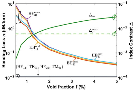
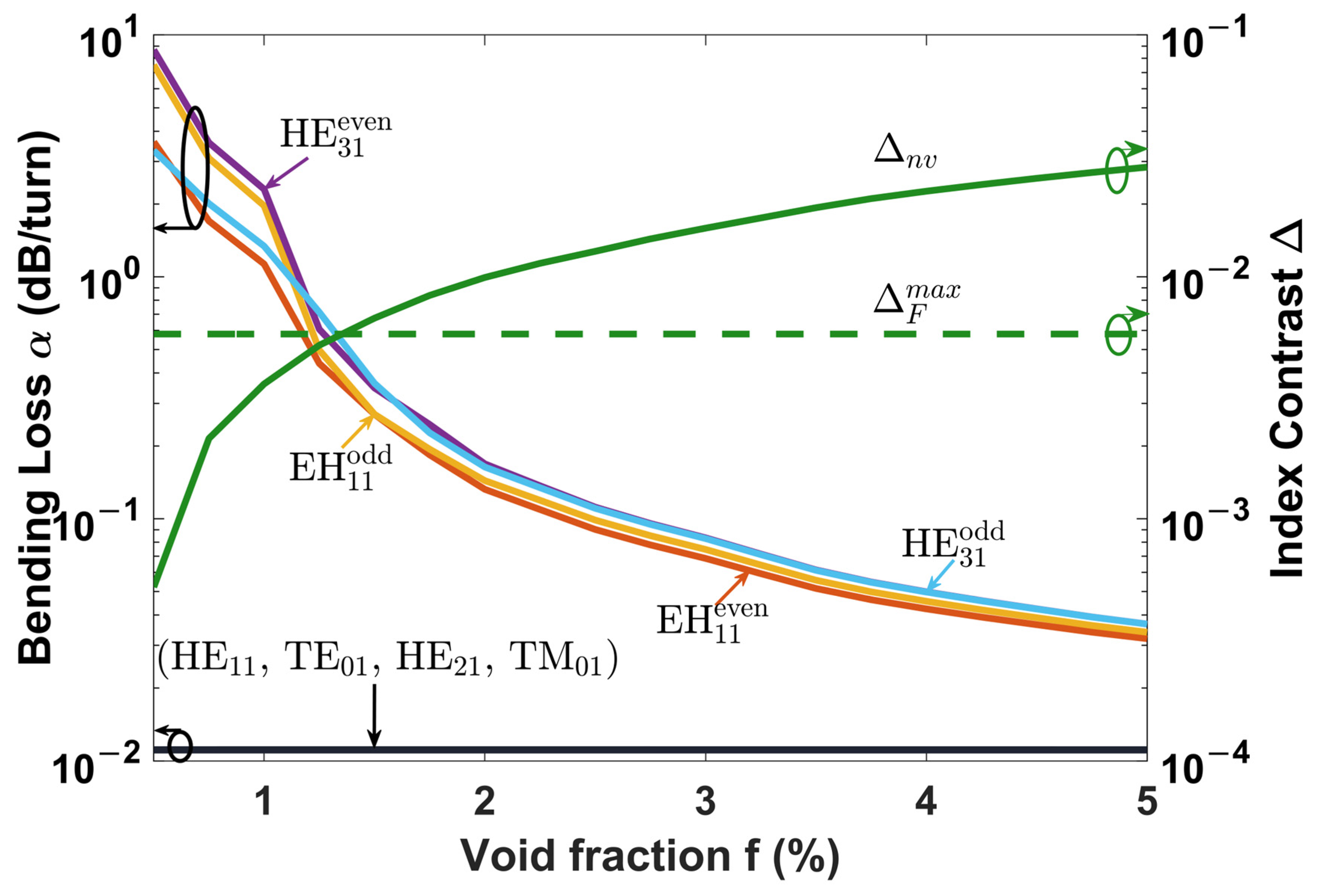
We next investigate the effect of f on the bending performance of the optimal NV-RCF (t = 8 µm, dt = 10.5 µm). The bend radius and wavelength remain fixed at Rb = 5 mm and λ = 1550 nm, respectively. Figure 5 presents bending-loss values for all guided modes of the NV-RCF as function of f, together with the corresponding refractive-index contrast Δ. The α values of the , , and modes remain nearly constant at around 0.0011 dB/turn, and are not affected by the change in void fraction. As discussed in Section 3.1, the strong core confinement of these modes is dominated by the core-cladding index contrast.
Figure 5.
Bending loss α (dB/turn) as a function of (f) for the ten guided modes of the NV-RCF (t = 8 µm, dt = 10.5 µm) at Rb = 5 mm and λ = 1550 nm (right axis). Left axis: relative index contrast between trench and cladding as a function of (f).
Higher-order mode groups, namely and , exhibit a strong dependence on f. As f increases from 0.5% to 5%, the bending loss decreases by nearly two orders of magnitude, reaching approximately 0.03 dB/turn at f = 5%. This reduction closely follows the increase in Δnv and the index depression provided by the nanovoid layer, which improves the confinement of the modes and reduces radiation leakage. We also observe that at low void fractions, both even and odd pairs of and witness a variation in loss of approximately 4 dB/turn. This variation in loss decreases and becomes negligible after a 1% void fraction.
These results represent a fundamental advantage of the nanovoid approach over conventional fluorine-doped trench designs. As shown in Figure 5, the maximum achievable index depression is due to dopant solubility limits and the mechanical instability of the glass matrix at higher doping concentrations [29]. The nanovoid layer can exceed this limitation by increasing the void fraction, providing a wider design space for fiber bending-loss optimization. Furthermore, the chromatic dispersion slope of the nanovoid layer closely follows that of fused silica [17], which creates additional opportunities for broadband spectral optimization.
3.3. Influence of the Bending Radius Rb, Wavelength λ, and Comparison with Basic RCF
To quantify the effectiveness of the nanovoid layer, we introduce an improvement factor Γ, defined relative to a reference RCF without a nanovoid layer:
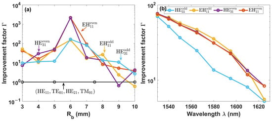
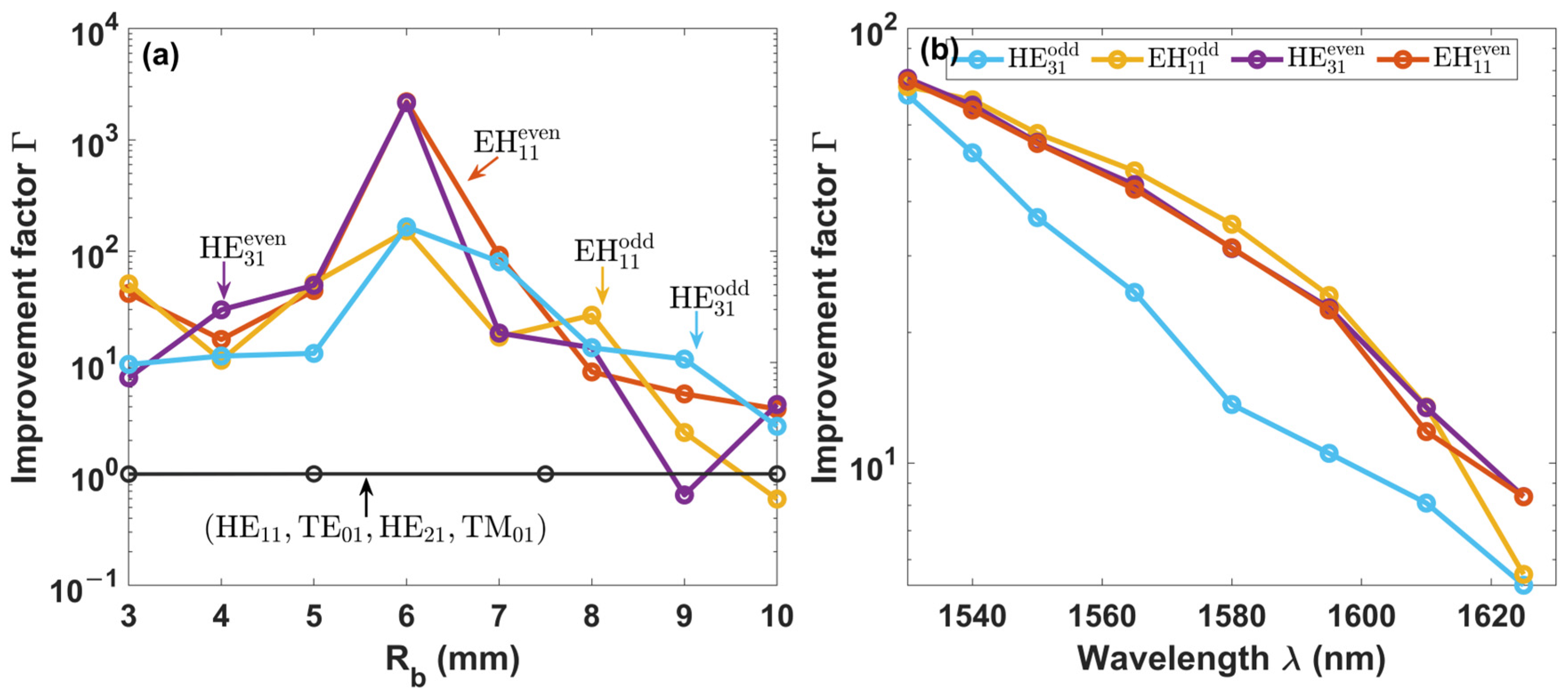
where αRCF and αNV-RCF represent the bending loss of the standard RCF (f = 0%) and the proposed NV-RCF (f = 2.5%), respectively. Figure 6 shows Γ as function of Rb for all propagating modes at 1550 nm. For the fundamental mode and lower-order modes , and , remains close to unity over all the bend radii investigated. This result is expected since these modes are already strongly confined in the reference RCF, and therefore benefit little from the additional confinement provided by the nanovoid layer.
Figure 6.
Improvement factor of the NV-RCF (t = 8 µm, dt = 10.5 µm, f = 2.5%) (a) compared to RCF (f = 0%) for all propagated modes as a function of the bending radius Rb at 1550 nm, and (b) as a function of the wavelength across the C and L bands for Rb = 5 mm.
In the case of the higher-order mode groups, and , significant improvements are observed under tight bending conditions. For bend radii between 3 and 8 mm, the improvement factor ranges from approximately one to three orders of magnitude. The largest enhancement occurs near Rb = 6 mm, where exceeds 102 for all higher-order modes and reaches values above 103 for and . The large improvement observed for the even polarized modes originates from their high bending loss in the reference RCF due to polarization sensitivity to bending, which is reduced when the nanovoid layer is introduced, as discussed and shown in Figure 5.
To assess whether this bending-loss advantage extends beyond the design wavelength of 1550 nm, we further evaluate Γ as a function of wavelength across the C and L band, at Rb = 5 mm, for the higher-order mode groups (Figure 6b). Γ remains well above unity across the entire C and L bands for both and . The improvement provided by the nanovoid layer is therefore maintained throughout the investigated wavelength range.
3.4. Influence on the Modal Separation
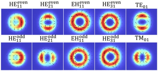
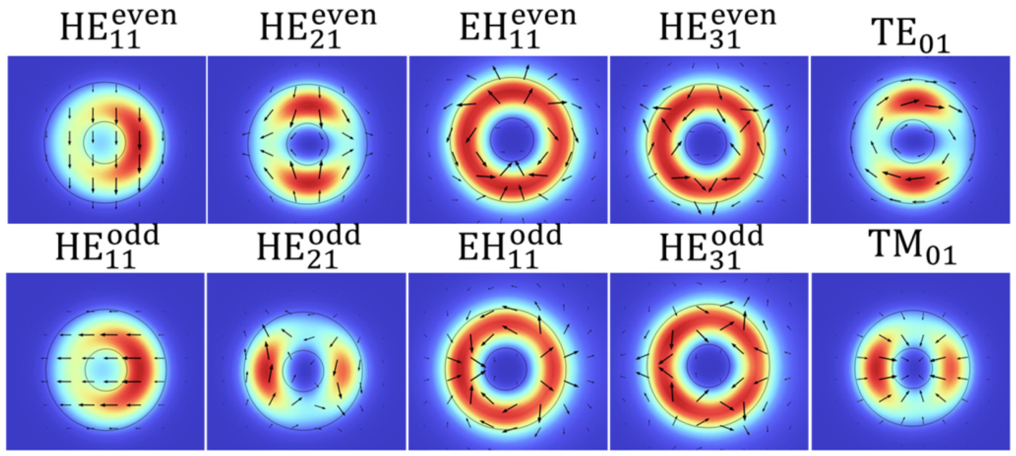
Figure 7 shows the intensity profiles of the vector modes supported by the NV-RCF at Rb = 5 mm. Although the lower-order modes exhibit some distortion under bending, their intensity remains well confined within the core region, which explains the low bending loss observed.
Figure 7.
Propagated mode profile intensity of the NV-RCF under a 5 mm bending radius and 1550 nm wavelength. Arrows demonstrate the electric field direction.
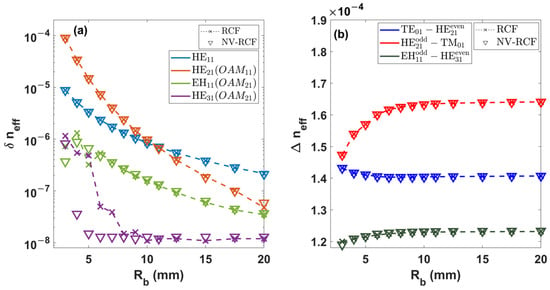
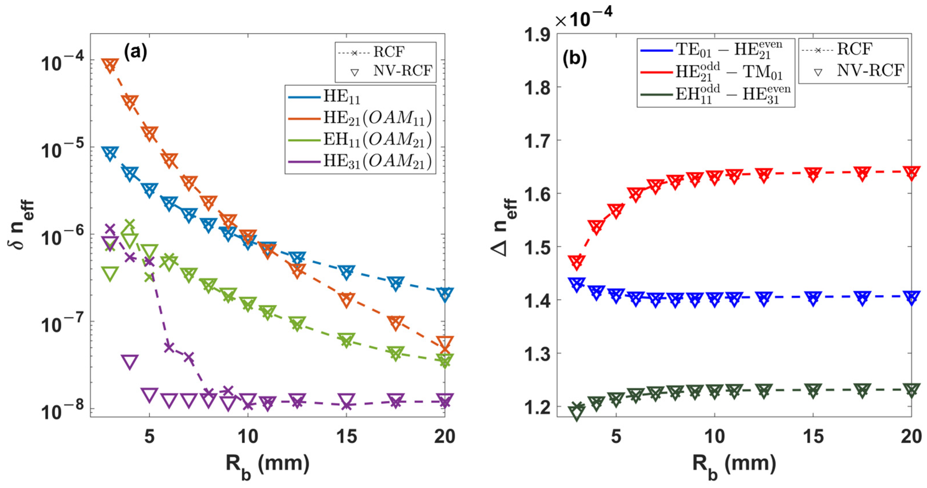
Stable propagation of the OAM modes requires two conditions: first, a modal degeneracy between the paired hybrid modes δneff < 10−6; second, a sufficient separation between adjacent vector modes Δneff > 10−4. Both conditions are evaluated for the optimized NV-RCF and compared against the reference RCF for bending radii ranging from 3 to 20 mm at a 1550 nm wavelength.
Figure 8a shows δneff for the hybrid mode groups as a function of Rb. At bend radii above 10 mm, all mode groups satisfy the degeneracy criterion and can be coupled into OAM modes. At Rb < 10 mm, δneff increases for all mode groups and the polarization degeneracy is progressively lifted. In particular, δneff between the pair approaches 10−4 at Rb = 3 mm in both fiber types, a value commonly found in birefringent fibers. For the higher-order pair, however, the NV-RCF demonstrates a ten-fold improvement in degeneracy compared to a basic RCF.
Figure 8.
(a) between hybrid mode pairs and (b) between adjacent mode groups in the optimized NV-RCF (triangles) compared to RCF (dashed line with cross marker) as a function of the bend radius Rb at a 1550 nm wavelength.
Figure 8b shows Δneff between adjacent mode groups ), (, and ( as a function of Rb for both NV-RCF and RCF. All separations in effective indices remain above the 10−4 threshold across the full range of bend radii investigated. The introduction of the nanovoid layer therefore does not compromise intermodal separation. A marginal increase in Δneff is observed for mode group pairs involving in the order of 10−7.
4. Conclusions
We proposed and numerically designed a nanovoid-assisted ring-core few-mode fiber (NV-RCF) for ultra-low bending loss and introduced a fully coupled mechanical–optical modeling framework to evaluate its performance. Our proposed 3D model achieves the closest agreement with reported experimental SMF-28 and RCF bending-loss data compared to the conformal mapping approach.
The optimized NV-RCF, with nanovoid ring parameters t = 8 μm and dt = 10.5 μm, was found to reduce bending loss of the higher-order and mode groups from approximately 45 dB/turn to near 0.1 dB/turn at a bend radius of 5 mm and a 1550 nm wavelength. The proposed NV-RCF reduces the bending loss by up to three orders of magnitude at tight-bending radii compared to a standard RCF; this improvement remains above unity through the entire C and L bands. The fundamental mode group, , and lower-order mode groups, and , remain weakly affected, as they are well confined in the high-contrast ring-core. At void fractions up to 5%, bending loss for the higher-order groups decreases more, reaching values near 0.03 dB/turn.
Modal analysis confirms that the NV-RCF preserves the modal properties of the original RCF across bending radii that are 3 mm to 20 mm in size. The intermodal effective-index separation remains above 10−4 between the adjacent modes, and the polarization degeneracy of the pair is improved by one order of magnitude compared to the reference RCF.
These results highlight the NV-RCF as a strong candidate for high-density space-division multiplexing in tight fiber routing. The design parameters also fall within the range of previously fabricated fibers [15,25], making the design viable and practical.
Author Contributions
Conceptualization, A.M., Y.M. and B.U.; methodology, A.M. and B.U.; software, A.M.; validation, A.M.; investigation, A.M.; resources, B.U.; data curation, A.M. and B.U.; writing—original draft preparation, A.M.; writing—review and editing, A.M. and B.U.; visualization, A.M. and B.U.; supervision, Y.M. and B.U.; project administration, B.U.; funding acquisition, B.U. All authors have read and agreed to the published version of the manuscript.
Funding
This research was funded by Fonds de Recherche du Québec-Nature et Technologies (grant number 304946).
Institutional Review Board Statement
Not applicable.
Informed Consent Statement
Not applicable.
Data Availability Statement
The main data supporting the findings of this study are available within the paper. Further information is available from the corresponding author upon request.
Conflicts of Interest
The authors declare no conflicts of interest.
Appendix A
Figure A1.
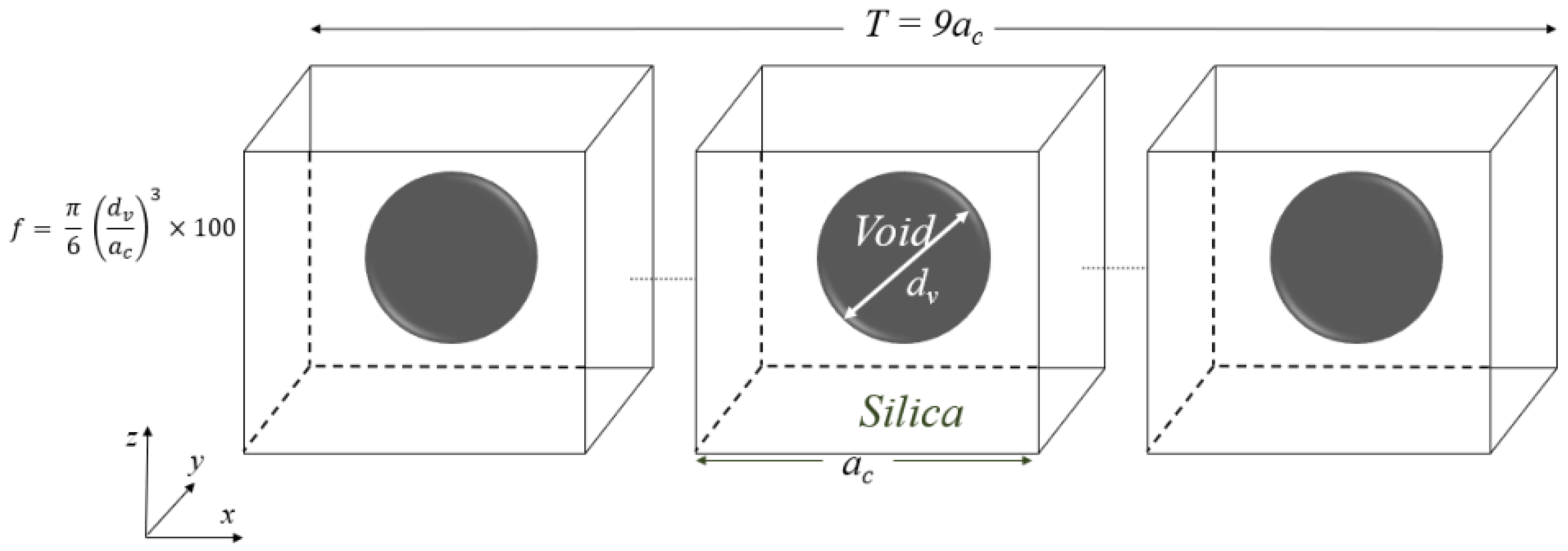
Illustration of the representative unit cell composed of a cubic silica and spherical air void used for the homogenization model. The unit cell is replicated into a slab of total length T for optical homogenization.
Appendix A.1. Effective Optical Parameters
The effective optical permittivity of the nanovoid silica is obtained using the S-parameter retrieval method [30]. A cubic unit cell containing a single spherical air void is modeled in CST Microwave Studio and replicated into a slab of total thickness T, as shown in Figure A1. The structure is excited by a normally incident plane wave using waveguide ports. PEC/PMC boundary conditions enforce periodicity on the transverse faces, and PML boundaries are applied along the propagation direction. Only the transmission coefficient S21 is extracted. The slab is treated as a homogeneous layer of thickness T, and S21 is expressed as follows [31]:
where the interface reflection coefficient is R = (1 − (1 + .
The complex effective permittivity is retrieved by inverting these relations for each void diameter dv and void fraction f. To account for the statistical distribution of void sizes, the retrieved permittivity values are weighted by the normal probability density function associated with the void size distribution:
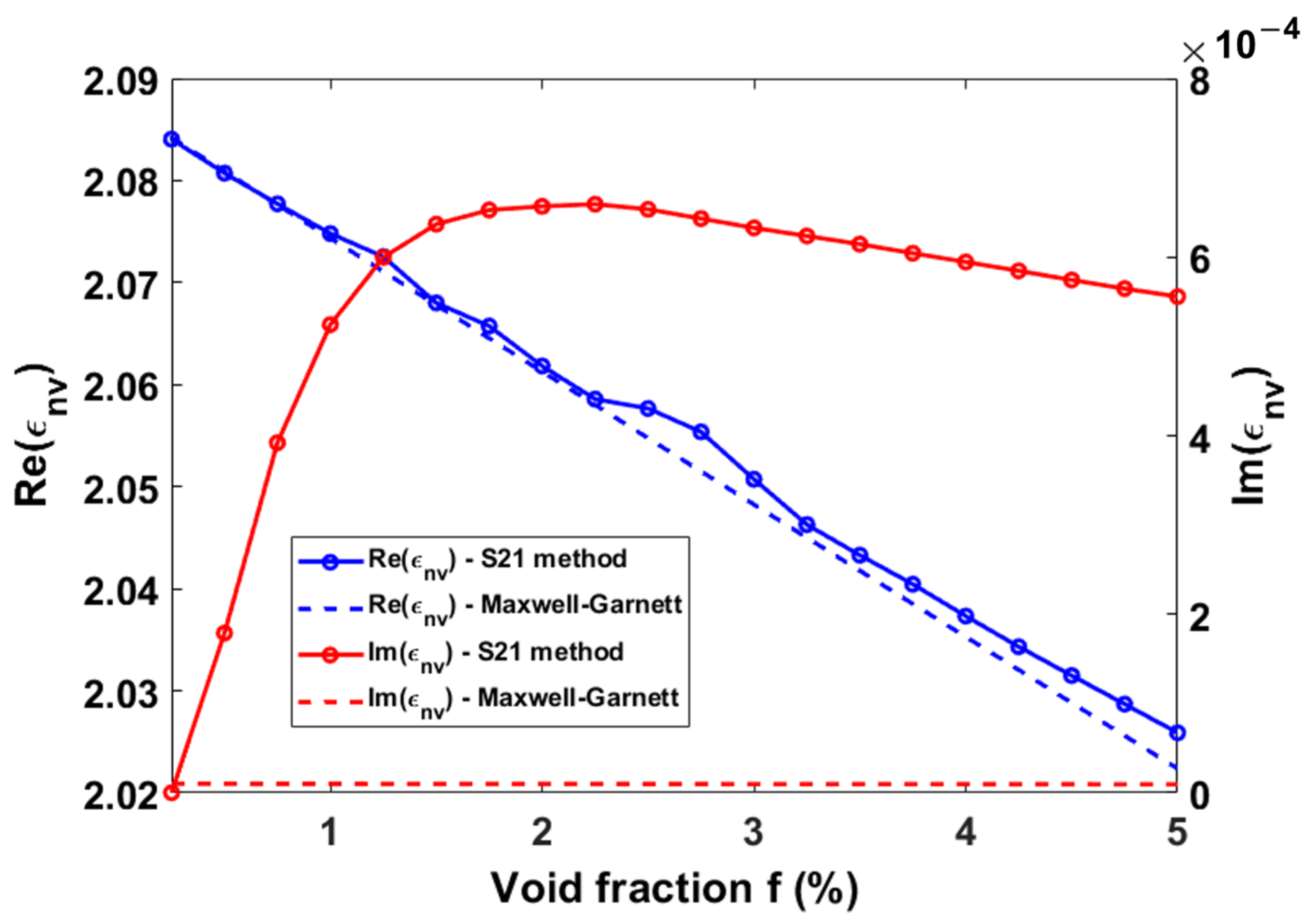
where is the normal probability density function with a mean µ = 150 nm and a standard deviation σ = 65 nm. The real and imaginary parts of are plotted in Figure A2 below. The resulting permittivity is compared to permittivity obtained from the standard Maxwell–Garnett theory [29]:
Our results agree well with Maxwell–Garnett theory for the real part of εnv. However, unlike the standard Maxwell–Garnett theory, the CST full-wave method takes into consideration the size of the voids and also yields the imaginary part of εnv, which the Maxwell–Garnett theory cannot predict.
Figure A2.
Real and imaginary parts of nanovoid silica effective permittivity as functions of the void fraction at 1550 nm obtained using the S21-retrieval method and the Maxwell–Garnett mixing theory.
Appendix A.2. Effective Mechanical Parameters
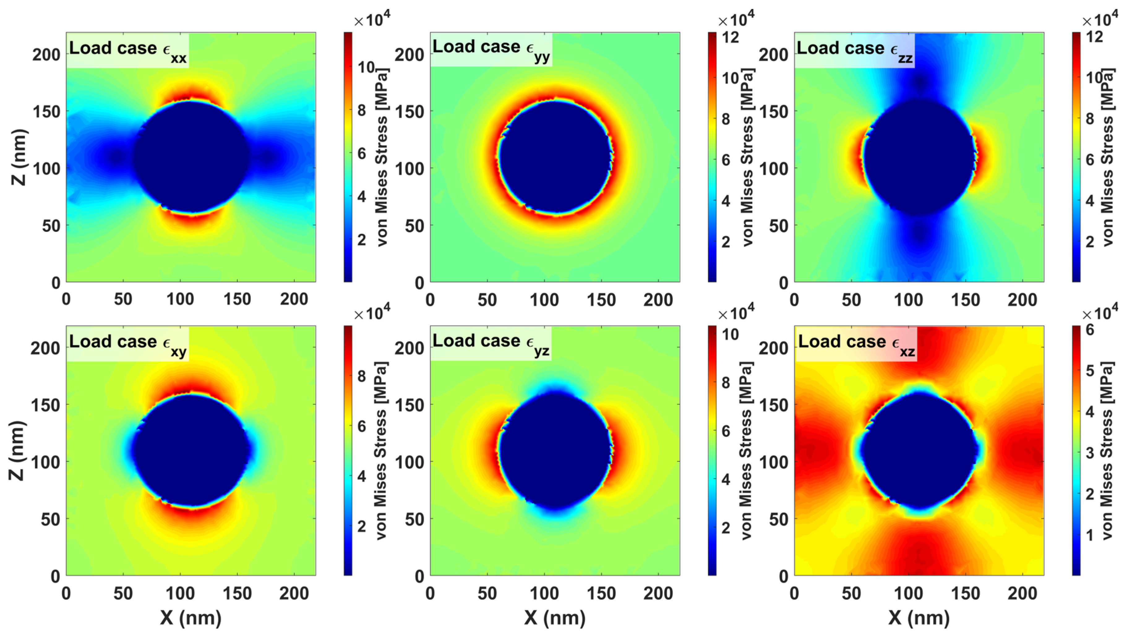
The effective mechanical properties of the nanovoid silica are extracted from unit-cell simulations performed in COMSOL Multiphysics. A cubic silica matrix containing a freely deformable spherical void is used as the representative volume element (RVE) (Figure A1). Periodic boundary conditions are applied on all faces of the unit cell to enforce mechanical periodicity. Simulations are performed for each pair (dv, f) by applying controlled strain states; the resulting Von Mises stress distribution around a representative nanovoid of size dv = 100 nm and at f = 5% is plotted in Figure A3 below.
Figure A3.
Von Mises stress distribution (MPa) around a single nanovoid (dv = 100 nm, f = 5%) in the XZ plane for each of the six unit-cell strain-load cases (εxx, εyy, εzz, εxy, εyz, εxz).
The homogenized elastic properties are extracted from the resulting stress–strain response. To account for the void size distribution, the stiffness tensors are weighted by the probability density function of the void diameter distribution:
where is the effective stiffness tensor of the nanovoid silica at void fraction f, and the normalized weights follow the same normal distribution defined in Appendix A.1. The effective density is computed using a simple volume-fraction mixture rule, neglecting the mass contribution of the air voids:
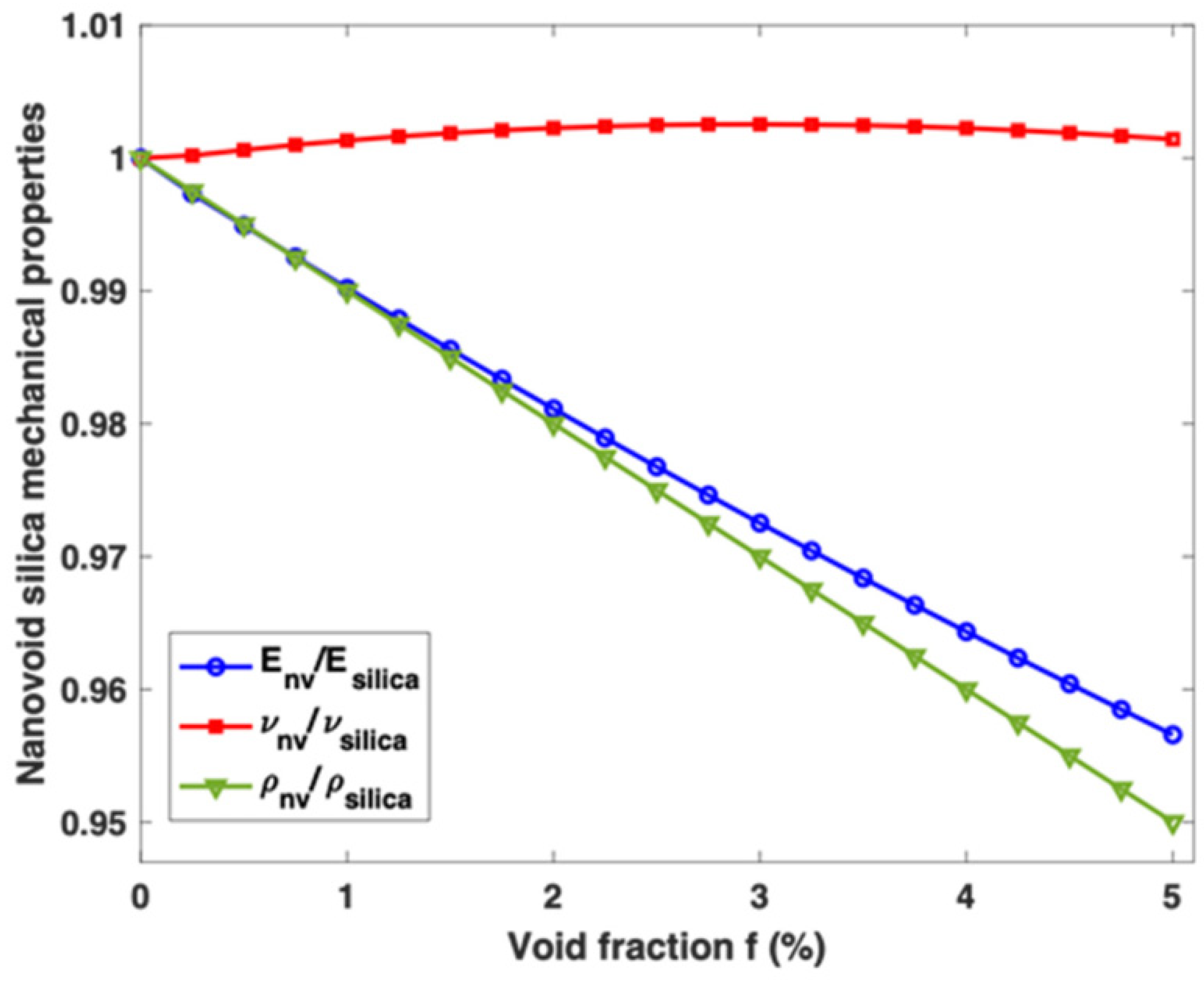
The resulting properties are normalized and plotted in Figure A4 below.
Figure A4.
Normalized Young’s modulus, Poisson’s ratio, and nanovoid silica density as functions of the void fraction.
References
- Liu, J.; Ma, Z.; Liu, J.; Dong, J.; Zhou, H.; Mo, S.; Wu, L.; Li, S.; Chen, Y.; Rusch, L.; et al. Optical fiber communications using orbital angular momentum modes. Optica 2026, 13, 602. [Google Scholar] [CrossRef] [Scilit]
- Liu, J.; Zhu, G.; Zhang, J.; Wen, Y.; Wu, X.; Zhang, Y.; Chen, Y.; Cai, X.; Li, Z.; Hu, Z.; et al. Mode division multiplexing based on ring core optical fibers. IEEE J. Quantum Electron. 2018, 54, 1–18. [Google Scholar] [CrossRef] [Scilit]
- Wang, H.; Liang, Y.; Zhang, X.; Chen, S.; Shen, L.; Zhang, L.; Luo, J.; Wang, J. Low-loss orbital angular momentum ring-core fiber: Design, fabrication and characterization. J. Light. Technol. 2020, 38, 6327–6333. [Google Scholar] [CrossRef] [Scilit]
- Jung, Y.; Kang, Q.; Zhou, H.; Zhang, R.; Chen, S.; Wang, H.; Yang, Y.; Jin, X.; Payne, F.P.; Alam, S.-U.; et al. Low-Loss 25.3 km Few-Mode Ring-Core Fiber for Mode-Division Multiplexed Transmission. J. Light. Technol. 2017, 35, 1363–1368. [Google Scholar] [CrossRef] [Scilit]
- Lee, J.; Song, J.; Kim, S. Analysis of Bending-Induced degradation of orbital angular momentum modes in optical fibers. Photonics 2019, 6, 97. [Google Scholar] [CrossRef] [Scilit]
- Gowri, M.; Joseph, T. Ultra-low-bending-loss trench-assisted ring-core fiber. Appl. Opt. 2025, 64, 9436. [Google Scholar] [CrossRef] [Scilit] [PubMed]
- Zhang, X.; Chen, S.; Wang, J. Weakly guiding graded-index ring-core fiber supporting 16-channel long distance mode division multiplexing systems based on OAM modes with low MIMO-DSP complexity. Opt. Express 2022, 30, 35828. [Google Scholar] [CrossRef] [Scilit] [PubMed]
- Chen, S.; Tong, Y.; Tian, H. Bend Property of Few-Mode Ring-Core Fiber Supporting Seven Spatial Modes for Mode-Division Multiplexed Applications. In Proceedings of the International Conference on Optical Communications and Networks (ICOCN2018); SPIE: Bellingham, WA, USA, 2019; p. 159. [Google Scholar]
- Heiblum, M.; Harris, J. Analysis of curved optical waveguides by conformal transformation. IEEE J. Quantum Electron. 1975, 11, 75–83. [Google Scholar] [CrossRef] [Scilit]
- Savović, S.; Djordjevich, A.; Savović, I. Theoretical investigation of bending loss in step-index plastic optical fibers. Opt. Commun. 2020, 475, 126200. [Google Scholar] [CrossRef] [Scilit]
- Birri, A.; McCary, K.; Wilson, B.A.; Blue, T.E. Thermally induced bend loss of silica optical fiber. IEEE Sens. J. 2018, 18, 6181–6187. [Google Scholar] [CrossRef] [Scilit]
- Watekar, P.R.; Ju, S.; Han, W.-T. Single-mode optical fiber design with wide-band ultra low bending-loss for FTTH application. Opt. Express 2008, 16, 1180. [Google Scholar] [CrossRef] [Scilit] [PubMed]
- Lian, Y.; Ren, G.; Jiang, Y.; Zhu, B.; Li, H.; Zheng, X.; Ren, W.; Jian, W.; Jian, S. Ultralow Bending-Loss Trench-Assisted Single-Mode optical fibers. IEEE Photonics Technol. Lett. 2017, 29, 346–349. [Google Scholar] [CrossRef] [Scilit]
- Nakajima, K.; Shimizu, T.; Matsui, T.; Fukai, C.; Kurashima, T. Single-mode hole-assisted fiber as a bending-loss insensitive fiber. Opt. Fiber Technol. 2010, 16, 392–398. [Google Scholar] [CrossRef] [Scilit]
- She, Y.-L.; Zhou, D.-J.; Chen, X.-Y.; Xia, A.-S. Study on ultralow bending loss of bend-insensitive single mode optical fiber. Opt. Fiber Technol. 2019, 50, 225–232. [Google Scholar] [CrossRef] [Scilit]
- Matsui, T.; Nakajima, K.; Goto, Y.; Shimizu, T.; Kurashima, T. Design of Single-Mode and Low-Bending-Loss Hole-Assisted fiber and its MPI characteristics. J. Light. Technol. 2011, 29, 2499–2505. [Google Scholar] [CrossRef] [Scilit]
- Li, M.-j.; Tandon, P.; Bookbinder, D.C.; Bickham, S.R.; McDermott, M.A.; Desorcie, R.B.; Nolan, D.A.; Johnson, J.J.; Lewis, K.A.; Englebert, J.J. Ultra-Low bending loss Single-Mode fiber for FTTH. J. Light. Technol. 2009, 27, 376–382. [Google Scholar] [CrossRef] [Scilit]
- Tandon, P.; Li, M.; Bookbinder, D.C.; Logunov, S.L.; Fewkes, E.J. Nano-engineered optical fibers and applications 1. Nanophotonics 2013, 2, 383–392. [Google Scholar] [CrossRef] [Scilit]
- Zheng, X.; Ren, G.; Huang, L.; Li, H.; Zhu, B.; Zheng, H.; Cao, M. Bending losses of trench-assisted few-mode optical fibers. Appl. Opt. 2016, 55, 2639. [Google Scholar] [CrossRef] [Scilit] [PubMed]
- Zhang, H.; Zhao, J.; Yang, Z.; Peng, G.; Di, Z. Low-DMGD, Large-Effective-Area and Low-Bending-Loss 12-LP-Mode Fiber for Mode-Division-Multiplexing. IEEE Photonics J. 2019, 11, 1–8. [Google Scholar] [CrossRef] [Scilit]
- Xie, Y.; Pei, L.; Zheng, J.; Ning, T.; Li, J.; Ai, B.; He, R. Design and characterization of Nanopore- assisted Weakly-Coupled Few-Mode fiber for simpler MIMO space division multiplexing. IEEE Access 2020, 8, 76173–76181. [Google Scholar] [CrossRef] [Scilit]
- Schermer, R.T.; Cole, J.H. Improved bend loss formula verified for optical fiber by simulation and experiment. IEEE J. Quantum Electron. 2007, 43, 899–909. [Google Scholar] [CrossRef] [Scilit]
- Velamuri, V.; Patel, K.; Sharma, I.; Gupta, S.S.; Gaikwad, S.; Krishnamurthy, P.K. Investigation of planar and helical bend losses in single- and Few-Mode optical fibers. J. Light. Technol. 2019, 37, 3544–3556. [Google Scholar] [CrossRef] [Scilit]
- Yao, X.S.; Chen, X. Polarization Measurement and Control in Optical Fiber Communication and Sensor Systems; Wiley: Hoboken, NJ, USA, 2022. [Google Scholar]
- Banawan, M.; Mishra, S.K.; Messaddeq, Y.; LaRochelle, S.; Rusch, L.A. Perfect vortex modes for nondestructive characterization of mode dependent loss in ring core fibers. J. Light. Technol. 2022, 40, 6548–6559. [Google Scholar] [CrossRef] [Scilit]
- Brunet, C.; Ung, B.; Wang, L.; Messaddeq, Y.; LaRochelle, S.; Rusch, L.A. Design of a family of ring-core fibers for OAM transmission studies. Opt. Express 2015, 23, 10553–10563. [Google Scholar] [CrossRef] [Scilit] [PubMed]
- Kominsky, D.; Pickrell, G.; Stolen, R. Generation of random-hole optical fiber. Opt. Lett. 2003, 28, 1409. [Google Scholar] [CrossRef] [Scilit] [PubMed]
- Urbanczyk, W.; Martynkien, T.; Bock, W.J. Dispersion effects in elliptical-core highly birefringent fibers. Appl. Opt. 2001, 40, 1911. [Google Scholar] [CrossRef] [Scilit] [PubMed]
- Corsi, A.; Chang, J.H.; Rusch, L.A.; LaRochelle, S. Design of highly elliptical core Ten-Mode fiber for space division multiplexing with 2 × 2 MIMO. IEEE Photonics J. 2019, 11, 1–10. [Google Scholar] [CrossRef]
- Qi, J.; Kettunen, H.; Wallén, H.; Sihvola, A. Different homogenization methods based on scattering parameters of dielectric-composite slabs. Radio Sci. 2011, 46, RS0E08. [Google Scholar] [CrossRef] [Scilit]
- Garnett, J.C.M. Colours in metal glasses and metal films. Philos. Trans. R. Soc. Lond. 1904, 203, 385–420. [Google Scholar] [CrossRef] [Scilit]

Disclaimer/Publisher’s Note: The statements, opinions and data contained in all publications are solely those of the individual author(s) and contributor(s) and not of MDPI and/or the editor(s). MDPI and/or the editor(s) disclaim responsibility for any injury to people or property resulting from any ideas, methods, instructions or products referred to in the content. |
© 2026 by the authors. Licensee MDPI, Basel, Switzerland. This article is an open access article distributed under the terms and conditions of the Creative Commons Attribution (CC BY) license.