1. Introduction
Optical wireless communication (OWC), including visible light communication (VLC), free-space optical (FSO) communication, and infrared laser links, is increasingly viewed as a complementary air interface for beyond-5G and 6G systems because optical carriers provide large unlicensed bandwidth, high spatial reuse, physical-layer confinement, and immunity to radio-frequency interference [
1,
2,
3,
4,
5,
6]. Recent OWC studies emphasize that future networks will not rely on a single radio or optical access technology. Instead, they will form heterogeneous network-of-networks in which radio, optical, fiber, satellite, aerial, and edge links are selected according to environment, traffic asymmetry, latency, reliability, and energy constraints [
7,
8]. This trend is directly relevant to drones, robots, autonomous vehicles, industrial mobile units, and distributed sensing tags. These platforms can benefit from narrow optical beams and spatially confined cells, but they cannot always carry a high-power optical transmitter, a precision gimbal, and a full acquisition-tracking-pointing subsystem.
Research on FSO has advanced rapidly toward higher link capacity. Modulation, coding, and diversity techniques have improved spectral efficiency and turbulence resilience [
5]. Higher-bandwidth sources and detectors, together with wavelength-division multiplexing, have raised the throughput of a single aperture, although the receiver has become the limiting element, since large collection area, wide field of view, and high bandwidth cannot be obtained simultaneously with conventional detectors. Improved pointing, acquisition, and tracking has extended reliable operation to mobile and long-range geometries, and recent surveys place these developments in the beyond-5G and 6G context [
6,
7]. They nonetheless share a common architectural assumption: that both ends can host an active optical transmitter, a high-bandwidth receiver, and a precision pointing subsystem. That holds for fixed infrastructure and backhaul terminals, but not for compact mobile platforms, where size, weight, power consumption, and cost (SWaP-C) are the binding constraints rather than link budget alone. Retroreflective links illustrate the alternative, since the mobile side dispenses with a laser source altogether [
9], so high-rate FSO and low-SWaP-C mobile operation are different regimes rather than competing goals.
A key difficulty in mobile OWC is therefore the distribution of optical complexity between the infrastructure and the mobile terminal. Conventional bidirectional FSO terminals place active optical transmitters and precision pointing optics at both ends of the link. This design supports symmetric high-throughput communication but increases aerial-side SWaP-C, as well as thermal load, calibration burden, and alignment sensitivity. In many drone-based mobile links, such symmetry is a severe limitation. The infrastructure may need to deliver downlink commands, schedules, map updates, synchronization, or interrogation signals at comparatively high optical power, while the mobile unit mainly returns acknowledgment packets, telemetry, inertial-state information, battery state, beam-alignment feedback, emergency messages, or short sensor bursts. Such uplink traffic is often latency-sensitive and reliability-sensitive, but not necessarily throughput-dominant.
Modulating retroreflector (MRR) communication addresses this traffic asymmetry by separating optical-carrier generation from mobile-side data modulation. The infrastructure illuminates the mobile unit with an interrogation beam, and the mobile terminal imposes uplink information by modulating and retroreflecting the incident carrier. The mobile unit therefore avoids carrying a laser transmitter. This concept has been demonstrated in high-speed retroreflective UAV-to-ground FSO links, including a 500 Mb/s outdoor link over 560 m using an electro-absorption-modulator MRR [
9], and has also been analyzed under UAV orientation fluctuation, tracking error, turbulence, and double-pass optical loss [
10]. Related visible-light backscatter and retro-VLC systems have shown the value of modulated retroreflection for low-power and battery-free optical uplink devices [
11,
12,
13]. However, an MRR alone does not solve the mobile downlink receiver problem. The mobile terminal still requires a compact, low-cost, and alignment-tolerant optical receiver.
Recent studies have also explored adaptive receiver technologies for OWC. Tunable liquid-crystal (LC) receivers dynamically redirect incident beams to improve optical coupling under varying alignment [
14], and liquid-lens (LL) imaging receivers use electrically controlled focal-length adjustment to enhance collection efficiency over different distances and incident angles [
15].
Fluorescent concentrators (FCs), also known as luminescent concentrators or fluorescent antennas, offer a complementary receive-side mechanism. An FC absorbs incident light over a large surface, re-emits it at a longer wavelength, and guides a fraction of the Stokes-shifted fluorescence toward an edge-coupled photodetector, providing a large collection interface without a high-capacitance detector or a narrow numerical-aperture lens. Because the wavelength changes in this process, the conservation of étendue no longer applies, and fluorescent antennas accordingly provide a wide field of view (FoV), optical gain, and wavelength-selective reception beyond conventional geometrical-optics trade-offs [
16,
17,
18,
19,
20,
21].
The two families differ in ways directly relevant to this work. LC- and LL-based receivers remain within geometrical optics and are therefore bound by the étendue constraint, are wavelength-agnostic and so cannot partition optical power spectrally, and require drive voltages, control electronics, and closed-loop alignment feedback at the mobile terminal. Conversely, they avoid the Stokes-shift photon-loss and fluorescence-lifetime bandwidth limits that constrain FCs, so the two approaches are complementary rather than competing. FC receivers, however, have been treated almost exclusively as receive-only components; the proposed architecture instead exploits their wavelength-selective response to partition optical power between downlink reception and MRR-based uplink remodulation, enabling compact bidirectional operation at the mobile terminal.
This paper proposes a compact mobile OWC transceiver module that integrates these two complementary devices. The FC provides a low-cost, large-area, wavelength-selective downlink receiver, while the MRR provides a low-SWaP-C uplink transmitter that remodulates an infrastructure-provided optical carrier. The module is not intended to replace a fully active high-capacity optical terminal. Rather, it targets mobile and semi-mobile aerial units for which the infrastructure can afford optical source power, receiver aperture, pointing search, and computation, while the mobile side must remain compact and power-constrained.
One of the main features of the proposed scheme is spectrally adaptive remodulation. The infrastructure does not simply choose one fixed wavelength for downlink and a separate fixed wavelength for uplink. Instead, it selects the interrogation wavelength and the downlink modulation depth jointly. The FC is treated as a wavelength-dependent optical power divider, where at wavelengths near the absorption peak, most of the incident power is absorbed and delivered to the FC receiver. On the other hand, at wavelengths in the pass-through region, most of the power reaches the MRR. At intermediate wavelengths on the absorption shoulder, the same beam can support both downlink reception and uplink remodulation. In this joint mode, the downlink information is carried on the interrogation beam, and the MRR imposes a second modulation on the residual carrier. The optimum wavelength-depth pair depends on the FC absorption spectrum, emission spectrum, pass-through loss, fluorescence conversion efficiency, edge-coupled receiver responsivity, FC bandwidth, MRR bandwidth, MRR insertion loss, round-trip optical loss, and the crosstalk caused by returning uplink light that is reabsorbed or scattered into the FC receiver.
The principal contributions of this paper are summarized as follows. First, we propose a compact FC-MRR bidirectional OWC architecture for low-SWaP-C mobile platforms, in which the optical complexity is shifted from the mobile terminal to the infrastructure, enabling low-power bidirectional communication without a mobile-side optical carrier source. Second, we identify and analytically characterize a non-orthogonal duplexing mechanism intrinsic to FC–MRR remodulation. The absorbed and pass-through optical-power fractions are complementary outcomes of the same incident photon flux and therefore form a one-dimensional spectral power-partition locus parameterized by the interrogation wavelength. The achievable downlink and uplink rates additionally depend on the downlink and uplink modulation depths, the selected PAM orders, and residual crosstalk. Conventional FC-only and MRR-only operation are recovered as limiting regimes near the two ends of this spectral locus. Third, we develop an analytical light-transfer model for the FC and integrate it with MRR remodulation, direct-detection signal-to-noise ratio (SNR), M-PAM bit-error-rate (BER) constraints, bandwidth limits, and a traffic-weighted utility function, yielding a unified framework for adaptive bidirectional OWC optimization. Finally, we present simulation results identifying the optimum wavelength-modulation-depth pairs for downlink-only, uplink-only, and joint bidirectional operation.
The remainder of this paper is organized as follows.
Section 2 reviews the relevant technologies and related work.
Section 3 introduces the proposed FC-MRR remodulation transceiver module and its spectral transfer model.
Section 4 presents the communication and optimization framework.
Section 5 provides the numerical results and discussion. Finally,
Section 6 concludes the paper.
2. Relevant Technologies and Comparisons
OWC is attractive for future mobile and edge networks because optical carriers provide high spatial reuse and avoid RF congestion, but mobility introduces acquisition, tracking, pointing, blockage, and orientation-variation challenges [
22,
23,
24,
25]. UAV-assisted FSO systems benefit from line-of-sight (LOS) geometry but are constrained by payload, vibration, beam wander, turbulence, attitude variation, and onboard power; a conventional active FSO payload requires a laser source, collimation optics, tracking sensor, beam steering, thermal control, and control electronics, all of which increase SWaP-C and reduce flight time.
The relevant design insight for this work is that many mobile OWC traffic patterns are asymmetric. A ground access point, ceiling access unit, wall-mounted edge node, or vehicle infrastructure unit may transmit high-power optical downlink commands, schedules, maps, software updates, and synchronization beacons. The mobile unit may need to return lower-rate information, such as acknowledgments, telemetry, localization feedback, channel-state information, beam-alignment feedback, and safety messages. In this regime, maximizing symmetric uplink throughput is less important than reducing mobile-side optical source power and pointing complexity.
MRRs are favorable under such asymmetry because the access point supplies the optical carrier. A retroreflective structure also returns the beam toward the source over a finite angular acceptance range, reducing remote-side pointing burden compared with an active laser transmitter. The trade-off is that the access point must illuminate the mobile aperture, collect a weak double-pass return, reject backscatter and background light, and maintain sufficient pointing margin. Practical MRR links are therefore highly sensitive to double-pass loss, modulator insertion loss, modulation depth, retroreflector aperture, and tracking error [
26,
27,
28,
29].
FC receivers provide a different advantage. They increase the effective receive aperture and FoV by converting incident photons into Stokes-shifted guided emission. They can therefore relax the requirement that a beam be focused directly onto a small detector. Their limitations are equally clear, since fluorescence lifetime, reabsorption, waveguide transport, edge-coupling loss, optical filtering, and detector bandwidth together impose a bandwidth-efficiency trade-off [
30,
31]. In addition, the FC response is strongly wavelength-dependent, which is normally treated as a constraint but is exploited here as a design resource.
Table 1 summarizes the operating regimes enabled by the proposed wavelength-dependent FC power partitioning and downlink modulation-depth control. The term remodulation is used because, in joint operation, the MRR imposes uplink information on an optical carrier that may already contain a downlink intensity-modulated envelope. Also,
Table 2 compares the proposed module with representative optical wireless communication approaches. Two columns carry the comparison directly: the mobile-side optical source and the wavelength-adaptive power split. The proposed architecture is the only entry that requires no onboard optical source while also using the receiver’s own absorption spectrum to allocate optical power between the two link directions, and it is the only entry supporting adaptive bidirectional operation through spectral remodulation.
3. Proposed FC-MRR Remodulation Transceiver Module
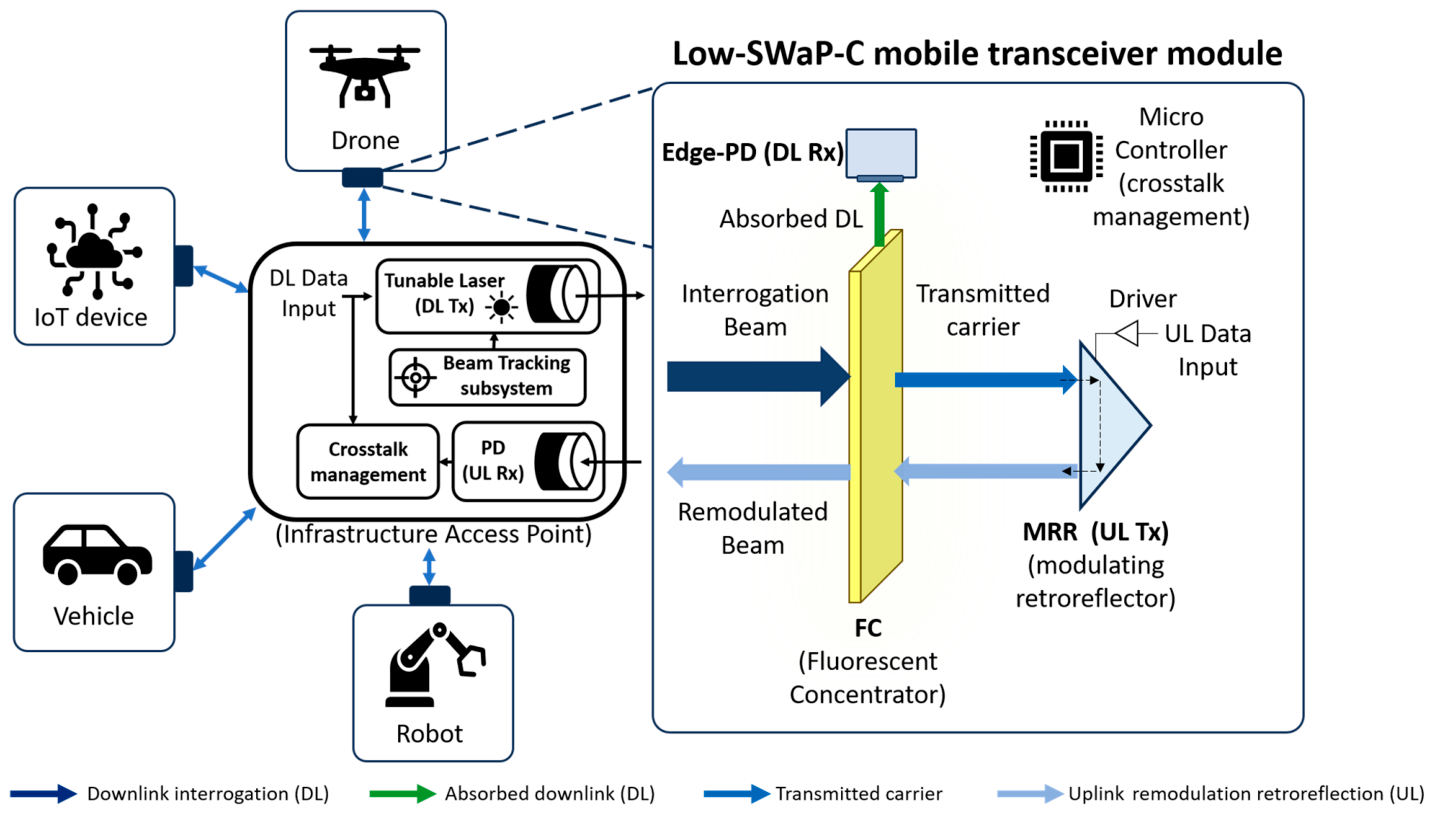
Figure 1 illustrates the proposed mobile-side transceiver module. The infrastructure access point transmits an interrogation beam whose center wavelength
and downlink modulation depth
are selected according to the desired traffic state. The incident beam first reaches the FC. A wavelength-dependent fraction is absorbed, Stokes-shifted, waveguided, and detected by an edge photodetector for downlink reception. The remaining fraction passes through the FC and illuminates the MRR. The MRR changes its effective reflectance or transmittance in response to the uplink data and retroreflects the beam toward the access point receiver.
The module can be physically implemented as a stacked optical structure comprising an FC front plate, an edge-coupled photodetector, a miniature driver/control circuit, a modulator, and a retroreflector. The FC is placed before the MRR so that it acts as the downlink receiver and spectral power divider. For wavelengths near the FC absorption maximum, most of the power is absorbed before reaching the MRR. For wavelengths beyond the absorption band, most of the power reaches the MRR, and for wavelengths on the absorption shoulder, both downlink reception and uplink remodulation are possible. The incident interrogation power can be written as [
32,
33]:
where
is the average optical power incident on the FC,
is a normalized zero-mean downlink waveform, and
is the infrastructure-controlled downlink modulation depth. In downlink-only operation,
is large. In uplink-only operation,
approaches zero so that the beam acts primarily as a continuous optical carrier for the MRR. In joint operation,
and the MRR remodulates the residual carrier that already contains a known downlink envelope.
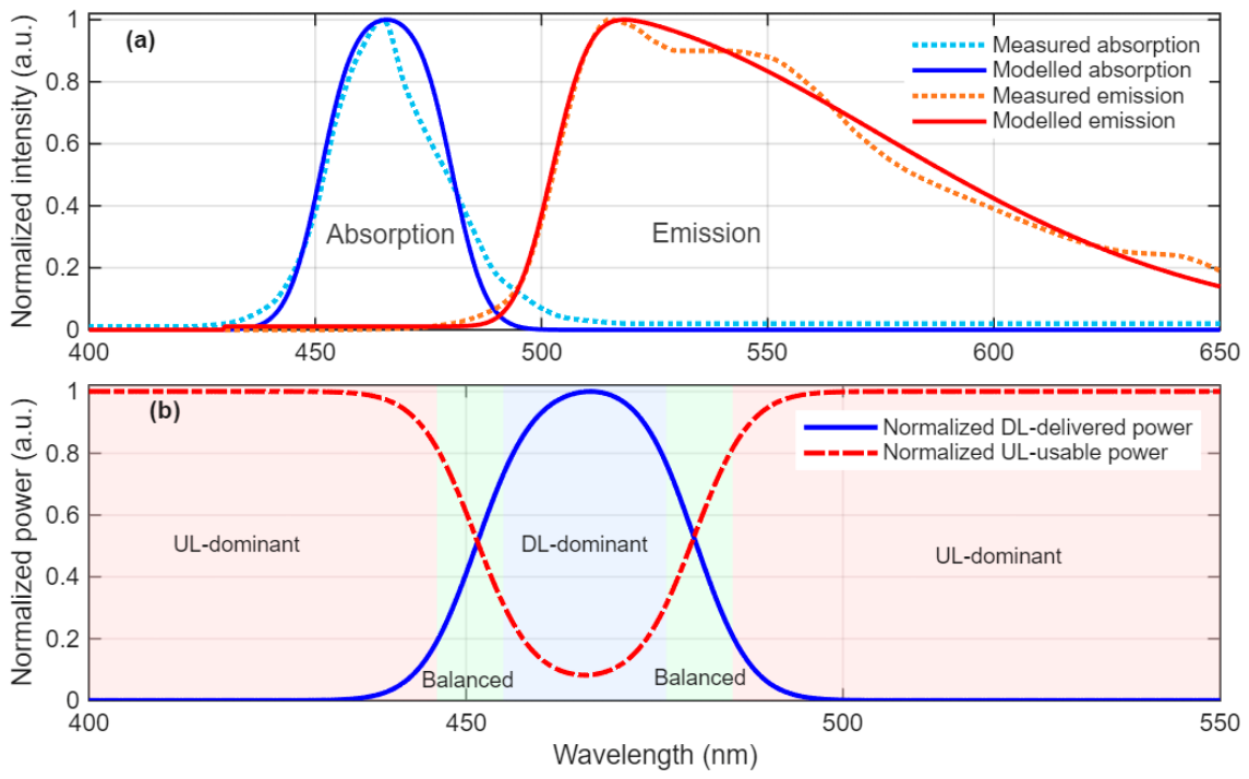
Figure 2 presents the FC spectral model used to evaluate the wavelength-dependent power partitioning of the proposed FC-MRR remodulation transceiver. In this module, the FC does not operate as an ideal binary filter. Instead, it behaves as a wavelength-dependent optical power divider, where a fraction of the incident interrogation beam is absorbed and converted into an edge-guided fluorescent signal for downlink reception, while the remaining fraction passes through the FC and is used as the optical carrier for MRR-based uplink remodulation. Therefore, the interrogation wavelength determines the DL/UL optical power split, whereas the downlink modulation depth controls the strength of the downlink envelope imposed on the interrogation beam.
The representative measured absorption and emission spectra of the FC are shown in
Figure 2a, together with the analytical spectral model used in the subsequent numerical analysis. To keep the model sufficiently general while preserving agreement with the measured FC behavior, the absorption response is described by a Gaussian optical-density function centered near the blue absorption band, while the emission spectrum is represented by a right-skewed Gaussian function to capture the long-wavelength photoluminescence tail. The purpose of this modeling approach is not to reproduce all microscopic fluorophore dynamics, but to provide a compact spectral model that captures the main features relevant to communication-system design, which are blue-band absorption, Stokes-shifted emission, and reduced absorption outside the FC absorption band.
For normally incident light, the optical density of the FC is modeled as [
17,
34]:
where
is the peak optical density,
is the absorption-center wavelength,
is the absorption spectral width,
is a residual background optical-density term,
is the wavelength-dependent absorption coefficient, and
is the FC thickness. The transmitted optical power passing through the FC is then given by the Beer-Lambert relation [
34]:
where
is the incident interrogation power and
is the single-surface Fresnel reflectance. This pass-through component corresponds to the optical power available to illuminate the MRR for uplink remodulation.
The corresponding absorbed optical-power fraction follows from the same photon accounting [
34,
35]:
Equations (3) and (4) therefore describe two complementary outcomes of the same incident photon flux, and their wavelength dependence is what allows the interrogation wavelength to partition optical power between downlink reception and uplink remodulation; this partitioning is examined quantitatively in
Section 5.5.
Using the photon-energy relation E = hc/λ and standard luminescent-concentrator photon accounting [
35], the absorbed photon flux is:
where
is Planck’s constant and
is the speed of light. For a wavelength-tunable narrowband interrogation beam, this expression directly gives the wavelength-dependent absorbed photon flux. For a broadband source, the total absorbed photon flux is obtained by integrating
over the incident spectrum.
The normalized emission spectrum is empirically fitted using the skew-normal density introduced by [
36]:
where
and
define the emission center and width,
controls the right-side spectral skew,
and
are the standard normal probability density and cumulative distribution functions, respectively, and
normalizes the spectrum such that
. This skewed form is used because the measured FC emission in general exhibits a sharp short-wavelength rise and a longer red-side tail, which cannot be represented accurately by a symmetric Gaussian alone.
Following established luminescent-concentrator photon-balance models [
17,
35], the edge-delivered downlink optical power is modeled by combining fluorescence quantum yield, total-internal-reflection trapping, propagation attenuation, reabsorption, and edge-coupling efficiency:
where
is the fluorescence quantum yield,
is the trapping factor,
is the edge-coupling and detector-coupling efficiency,
is the matrix attenuation coefficient, and
is the average guided propagation length. The factor
accounts for the photon-energy difference between absorbed and emitted wavelengths.
For communication-system interpretation, the normalized DL-delivered and UL-usable powers are defined as:
Figure 2b plots these two normalized quantities in the 400–550 nm region, where the FC absorption band governs the strongest DL/UL trade-off. Near the absorption center,
is high and
is strongly suppressed, corresponding to a DL-dominant operating region. At wavelengths far from the absorption peak, the FC becomes a low-loss pass-through element, and the UL-usable carrier dominates. On the two absorption shoulders, the absorbed and transmitted powers are both non-negligible, producing balanced DL/UL regions suitable for simultaneous downlink reception and MRR-based uplink remodulation. This spectral power-partitioning behavior provides the physical basis for the proposed adaptive remodulation strategy.
The MRR changes its optical return coefficient according to the uplink waveform. Let
be the normalized uplink signal,
the MRR modulation depth,
the average retroreflective coefficient, and
the modulation contrast. Following conventional MRR modulation models [
9,
10,
26,
27,
28,
29], we use the following first-order effective return coefficient:
Following standard retroreflective link models [
9,
10,
26], the returned optical power collected at the infrastructure receiver can be approximated as:
where
and
are the forward and backward FC pass-through factors, and
includes retroreflector efficiency, two-way propagation loss, aperture coupling, pointing loss, optical filtering, and infrastructure-side receiver collection. Expanding this product shows why the link operates as a remodulation system:
The desired uplink term is proportional to , whereas is a known downlink envelope generated by the infrastructure and is a multiplicative remodulation term. The access point can reduce the known-envelope component through self-interference cancelation because is locally known. However, imperfect cancelation, detector nonlinearity, modulator nonlinearity, and timing mismatch produce residual self-interference that must be included in the link budget.
4. Communication and Optimization Model
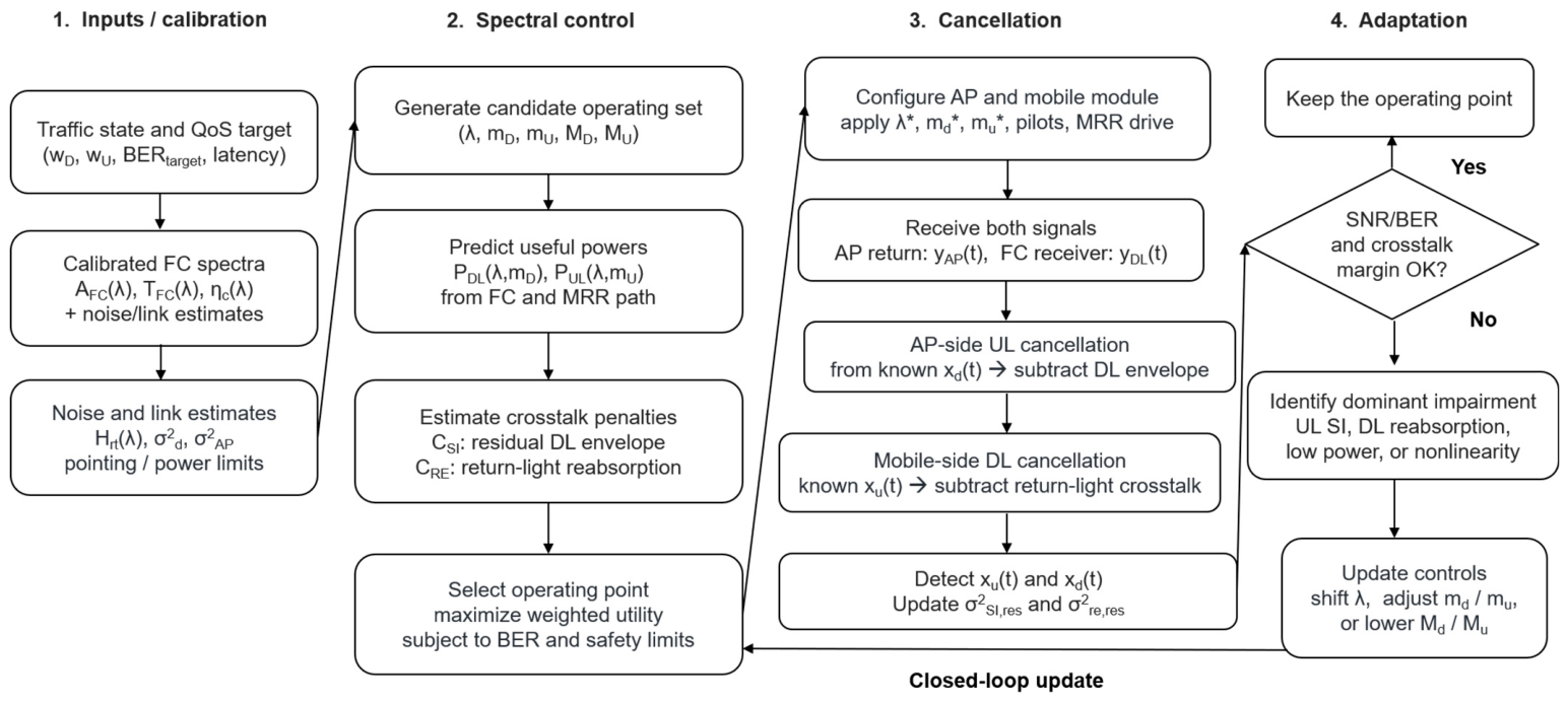
This section develops a communication model for the proposed FC-MRR remodulation transceiver. The model accounts for both the FC-based downlink receiver and the MRR-based uplink return path. In addition, because the same optical carrier can contain a downlink envelope and can subsequently be remodulated by the MRR, the model explicitly includes crosstalk terms in both directions. On the uplink side, the access point must suppress the locally known downlink envelope contained in the retroreflected signal. On the downlink side, the mobile module must suppress or account for return-path light that is reabsorbed, scattered, or fluorescently coupled into the FC receiver. Therefore, the crosstalk-reduction algorithm in
Figure 3 is interpreted as a bidirectional impairment-control loop rather than an uplink-only cancelation procedure.
Under intensity modulation and direct detection [
33], the downlink photocurrent generated by the FC edge receiver can be written as:
where
is the DC photocurrent associated with the average fluorescent power,
is the edge-detector responsivity at the fluorescence emission wavelength,
is the effective FC collection factor,
is the useful absorbed fraction,
is the incident interrogation power,
is the downlink modulation depth, and
is the normalized downlink waveform. The term
denotes returning-light crosstalk produced by retroreflected uplink light that is reabsorbed, scattered, or coupled into the FC downlink receiver. The noise term
includes shot noise, thermal noise, background-light noise, and receiver-electronics noise.
In joint DL/UL operation,
may contain components correlated with the local MRR drive waveform
, the returned carrier level, and the multiplicative remodulation term. Since
is generated by the mobile controller, the FC receiver can use the local MRR drive signal, pilot symbols, or calibration sequences to estimate and reduce this downlink-side crosstalk. The crosstalk-reduced downlink signal is represented as:
where
is the estimated return-light crosstalk component obtained from the local uplink drive state and pilot-assisted coupling estimation. The residual downlink crosstalk variance is:
For numerical modeling, this residual term can be parameterized as:
where
is the returning MRR optical power incident on the FC side,
is the wavelength-dependent coupling coefficient from the return path into the FC receiver,
represents residual return-light cancelation error, and
represents residual multiplicative remodulation distortion. This parameterization does not assume perfect crosstalk cancelation; instead, it treats the remaining downlink impairment as a measurable penalty term.
The two residual coefficients are not free parameters but are defined with respect to the uncancelled interference level. Each coefficient is the fraction of interference power remaining after cancelation, so the cancelation depth is
in dB:
gives about 5.2 dB of suppression,
about 2.2 dB, and
the uncancelled worst case. The same normalization applies to the uplink coefficients below. This range is conservative relative to reported optical self-interference cancelation, which reaches roughly 20–30 dB over practical bandwidths [
37], and since the analysis also spans the uncancelled limit, the conclusions are bracketed by both an optimistic and a pessimistic assumption.
The coupling coefficient
is likewise determined by the FC transfer model rather than assumed independently. Light returned by the MRR re-enters the FC at the interrogation wavelength, so that a fraction
is absorbed and follows the same fluorescence, trapping, and edge-delivery chain as the downlink signal:
where
accounts for the small non-absorptive component scattered directly into the edge receiver, set here to a small fraction of the absorptive term. Equation (16) therefore fixes
once the FC parameters of
Section 3 are specified, and shows that the return-light coupling is largest precisely where downlink reception is strongest. These coefficients are also directly measurable:
from the FC edge photocurrent with
,
from the residual-to-uncancelled interference power ratio at the access point with
, and the multiplicative terms from bidirectional operation once these are removed.
The resulting downlink electrical SNR, defined following standard IM/DD SNR conventions [
33], is:
where
is the downlink receiver noise variance excluding residual return-light crosstalk.
For the uplink, the access-point receiver collects the retroreflected optical signal from the MRR. Using the remodulation expression introduced in
Section 3, the AP receiver photocurrent can be represented as:
where
is the AP receiver responsivity,
and
are the forward and backward FC pass-through factors,
is the round-trip optical-channel factor,
is the average retroreflective coefficient,
is the MRR modulation contrast,
is the uplink modulation depth,
is the normalized uplink waveform, and
is the AP receiver noise.
The model below includes turbulence-induced scintillation and pointing error as multiplicative fading on the return path. For analytical tractability, however, the rate results of
Section 5.1,
Section 5.2,
Section 5.3 and
Section 5.4 are evaluated at a static LOS operating point, obtained by setting these fading factors to their mean values; the penalty incurred when they are active is quantified in
Section 5.6.
Although
appears as a single factor in Equations (10) and (18), it follows from the retroreflective link geometry. Since
and
already account for the modulator return efficiency and
is the power incident on the mobile module,
is the return-path geometric and optical coupling gain [
9,
10]:
where
is the deterministic geometric and optical coupling gain,
is the link range,
and
are the receiver and retroreflector aperture diameters,
is the AP optical-train and filter efficiency, and
is the one-way atmospheric transmittance along the return path. The factors
and
are unit-mean random variables representing turbulence-induced scintillation and pointing error, and are specified below. The return divergence
is bounded below by the diffraction limit and, for practical corner-cube or MRR arrays, is dominated by the fabrication-limited divergence
; the minimum operator represents the short-range regime in which the returned beam underfills the receiver aperture. Since the collected fraction scales as
only in the diffraction-limited regime, and this variation is negligible compared with that of
over 400–550 nm,
is treated as spectrally flat in the numerical study.
The desired uplink term is proportional to
, whereas
is a known downlink envelope generated by the infrastructure, and
is a multiplicative remodulation term. Since
is locally known at the AP, the AP can reconstruct the downlink envelope and perform self-interference cancelation or known-envelope equalization before uplink detection. The effective uplink signal after AP-side cancelation is written as:
where
denotes the AP-side cancelation and equalization operation. Imperfect cancelation, timing mismatch, detector nonlinearity, modulator nonlinearity, and estimation error produce residual self-interference. Optical cancelation analyses likewise identify amplitude, phase, and delay mismatch as principal limits on broadband cancelation [
37].
The residual self-interference variance is modeled as:
where
is the interference induced by the known downlink envelope and the remodulation product, and
is the reconstructed self-interference term. A first-order parameterization is:
where
represents residual known-envelope cancelation error and
represents residual distortion associated with the multiplicative downlink-uplink remodulation term. As in the downlink case,
and
denote the fractions of interference power remaining after AP-side cancelation of the known downlink envelope and of the multiplicative remodulation term, with cancelation depths
and
in dB.
The effective uplink SNR after cancelation is then [
33,
38]:
where
is the AP receiver-noise variance excluding residual remodulation self-interference.
The usable bandwidths of the downlink and uplink are technology limited. The FC downlink bandwidth is constrained by the optical source, fluorescence lifetime, reabsorption dynamics, waveguide path distribution, detector capacitance, and receiver electronics. The uplink bandwidth is constrained primarily by the MRR modulator and the AP receiver. We define:
and
If the FC response is approximated as a single-pole fluorescence-limited process, then
. In practice,
is not only the intrinsic photoluminescence lifetime but also an effective response time including reabsorption, waveguide propagation, edge coupling, detector capacitance, and receiver electronics [
17]. Similarly,
depends on modulator technology, aperture, drive voltage, wavelength, insertion loss, and packaging parasitics.
The single-pole relation only converts an effective response time into a bandwidth; Equation (24) requires a numerical value for the FC bandwidth, so a measured
dB bandwidth may be substituted directly. Since an FC exhibits multiple fluorescence lifetimes and dispersive waveguide transport [
17,
30,
31], the relation is optimistic and the FC bandwidth is read as an upper bound, with
Section 5 baseline chosen conservatively; because the effective response time is dominated by emission-side dynamics, the resulting error is largely common across the interrogation band and rescales the downlink rate rather than reshaping its spectral dependence, an effect equivalent to a change in the traffic weight.
For intensity modulation and direct detection (IM/DD), the BER of
-PAM over an AWGN-equivalent channel is approximated by [
33]:
where
is the Gaussian Q-function and
is the corresponding electrical SNR. The link rate is selected under the hard-decision forward-error-correction (FEC) threshold
as:
where
and
denote the allowed downlink and uplink modulation-order sets, respectively. In this study, symbol rates are set to the maximum usable bandwidth of the corresponding FC or MRR path, while the modulation order is adapted according to the estimated SNR.
For a required traffic ratio, the optimum interrogation wavelength, downlink modulation depth, uplink modulation depth, and modulation formats are obtained by maximizing a weighted utility [
39]:
subject to
Here,
and
are the downlink and uplink traffic weights,
and
are normalization constants, taken as the maximum single-direction rates attainable over the search set, so that both normalized terms lie in
and the traffic weights carry their intended relative meaning,
penalizes residual return-light crosstalk at the FC downlink receiver,
penalizes residual AP-side self-interference in the retroreflected uplink, and
is the wavelength-dependent optical-power or safety constraint. The penalty terms may be normalized as:
where
is a small positive constant that prevents division by zero when the useful signal term vanishes, as occurs at
or
. It is set several orders of magnitude below the smallest nonzero signal term encountered in the search, so that it is inactive at all feasible operating points and the reported optima are insensitive to its value. This formulation allows the same physical module to operate as a downlink receiver, an uplink retro-transmitter, or a joint bidirectional terminal primarily by adapting the interrogation wavelength and downlink modulation depth at the infrastructure side, with additional adjustment of the MRR drive condition, modulation format, and cancelation overhead when required.
It is worth making explicit why the optimization in Equation (28) cannot be decomposed into two independent single-link problems. As expressed in Equations (10) and (18), the retroreflected uplink signal is multiplied by the downlink envelope, so the downlink waveform is the optical carrier of the uplink itself, and the residual uplink self-interference of Equation (22) grows as
. A second coupling acts in the spectral domain, since the absorbed and pass-through components originate from the same incident photon flux, as quantified in
Section 5.5. The pair
therefore does not represent two separately tunable design parameters but a single coupled operating point, and the objective in Equation (28) is non-separable, which is why a weighted-utility formulation over the joint variable set is required.
Figure 3 summarizes how the optimization model is used during operation. The algorithm first loads the calibrated FC spectral response, including
,
, and the estimated return-light coupling coefficient
. It then selects
according to the DL/UL traffic weights. A wavelength near the FC absorption peak favors downlink reception because
is large and the pass-through carrier is suppressed. A pass-through wavelength favors uplink remodulation because
is large and more optical carrier reaches the MRR. An absorption-shoulder wavelength supports joint DL/UL operation because both the absorbed and transmitted power components are non-negligible.
After the initial operating point is selected, pilot symbols or training sequences are used to estimate timing, gain, and crosstalk coefficients. At the AP receiver, the downlink waveform is locally known because it is generated by the infrastructure. Therefore, the AP reconstructs and cancels the downlink-envelope component contained in the retroreflected signal before uplink detection. At the mobile receiver, the MRR drive waveform and the MRR modulation state are locally known because they are generated by the mobile controller. Therefore, the FC receiver can estimate and reduce the return-light component coupled into the downlink path. In both directions, imperfect cancelation is not ignored; the remaining residual terms are included in and , respectively.
If the estimated BER and crosstalk penalties satisfy the constraints, the operating point is maintained; otherwise, the controller updates the wavelength, modulation depths, modulation order, or pilot overhead, as shown in
Figure 3. The adaptation process is an iterative control loop rather than a gradient-based optimization. At each iteration, the controller evaluates the measured downlink and uplink SNRs, estimated BERs, and residual crosstalk levels, and updates the interrogation wavelength, modulation depths, modulation order, or pilot overhead; the operating point is regarded as converged when all communication-quality constraints are satisfied, and no further update improves the utility of Equation (28). The resulting procedure is an exhaustive evaluation over a bounded discrete set, in which the M-PAM orders follow in closed form as the largest values satisfying the BER constraint of Equation (26), so the cost is
closed-form evaluations. This is a deliberate choice rather than a limitation, since the objective is non-separable in
and discontinuous in the modulation orders, so gradient-based methods do not apply. Dynamic misalignment likewise also guarantees that the returned point is the global optimum over it and that the loop terminates in a finite number of iterations.
5. Numerical Results and Discussion
This section evaluates the proposed FC-MRR remodulation transceiver using the spectral, communication, and optimization models developed in
Section 3 and
Section 4. The purpose of the numerical study is threefold. First, it clarifies how the interrogation wavelength controls the optical power partition between FC-based downlink reception and MRR-based uplink remodulation. Second, it identifies how the downlink modulation depth and modulation format should be adapted as the traffic demand shifts from downlink-dominant to uplink-dominant operation. Third, it quantifies the effect of imperfect bidirectional cross-talk cancelation, which is unavoidable in a practical implementation.
The simulations use the representative blue-absorbing/yellow-emitting FC spectral response of
Section 3, with the downlink-delivered and uplink-usable powers computed from the same transfer model including surface reflection, absorption, fluorescence conversion, trapping, reabsorption, attenuation, and edge coupling. The FC is therefore treated as a wavelength-dependent optical power divider rather than an idealized binary filter.
The FC spectral parameters are those of the reference blue-absorbing/yellow-emitting response of
Section 3, with quantum yield, trapping efficiency, edge-coupling efficiency, and matrix attenuation from reported luminescent-concentrator characterizations [
17,
35] and a Fresnel reflectance corresponding to a PMMA host (
);
and
are taken from reported MQW-class MRR devices [
26,
27,
28,
29], satisfying the safety constraint of Equation (29), and the responsivities correspond to silicon photodiodes with thermal and shot noise at room temperature. On the communication side, the downlink and uplink bandwidths are 80 MHz and 20 MHz as constrained by Equations (24) and (25), and link rates are evaluated using maximum-bandwidth M-PAM under the hard-decision FEC BER threshold
[
33], reflecting the bandwidth and linearity limits of practical MRR devices. The rate-map, traffic-weight, and component-sensitivity results assume
about 5.2 dB of suppression, since reported optical cancelation is limited by amplitude, phase, and delay mismatch [
37].
5.1. Wavelength-Dependent Rate Maps Under Moderate Residual Crosstalk
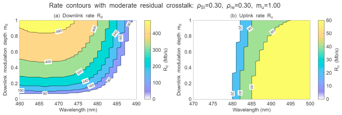
Figure 4 shows the simulated downlink and uplink rate contours as functions of interrogation wavelength and downlink modulation depth
. Unlike an idealized perfect-cancelation case, the rate maps in this figure are evaluated under a moderate residual-crosstalk condition, with
and
. Here,
represents the residual AP-side self-interference after cancelation of the known downlink envelope in the retroreflected uplink signal, while
represents the residual return-light crosstalk coupled into the FC downlink receiver. The MRR uplink modulation depth is fixed at
so that the effect of wavelength and downlink modulation depth can be isolated.
Figure 4.
Rate contours under moderate residual crosstalk. (a) Downlink and (b) uplink data-rate contours as functions of interrogation wavelength and downlink modulation depth , with , , and . The downlink is favored near the FC absorption-centered region, whereas the uplink is favored toward the FC pass-through side. The contour shifts show that residual remodulation crosstalk couples wavelength selection and modulation-depth control in practical bidirectional operation.
Figure 4.
Rate contours under moderate residual crosstalk. (a) Downlink and (b) uplink data-rate contours as functions of interrogation wavelength and downlink modulation depth , with , , and . The downlink is favored near the FC absorption-centered region, whereas the uplink is favored toward the FC pass-through side. The contour shifts show that residual remodulation crosstalk couples wavelength selection and modulation-depth control in practical bidirectional operation.
Figure 4a shows that the downlink rate is highest near the FC absorption-centered wavelength region, where the absorbed optical power and edge-delivered fluorescent signal are large. The downlink rate also increases with
, because a deeper downlink envelope produces a larger received modulation current at the FC edge detector. At small
, the downlink signal is weak even when the wavelength lies close to the absorption peak. At longer wavelengths, the FC absorption decreases, and the downlink rate drops even for relatively large
. Thus, the downlink contour map confirms that both spectral absorption and modulation depth are necessary to sustain a high-rate FC-based downlink.
Figure 4b shows the complementary uplink behavior. The uplink rate is suppressed near the absorption-centered region because the FC attenuates the optical carrier before it reaches the MRR and also affects the retroreflected return path. As the wavelength shifts toward the pass-through side of the FC spectrum, more optical power reaches the MRR and the uplink rate increases. The uplink contours also depend on
, because residual self-interference from imperfect cancelation of the downlink envelope becomes larger as
increases. Therefore,
is not only a downlink-control variable; it also affects the uplink penalty in the remodulation link.
The block-like contour transitions in both panels originate from the discrete -PAM modulation-order selection and the FEC BER constraint. A small change in wavelength or can move the estimated SNR across the threshold required for a higher or lower modulation order, resulting in step-like rate contours. This behavior is expected in an adaptive optical wireless link and should be interpreted as a modulation-format transition rather than a numerical artifact.
Figure 4 therefore shows that simultaneous bidirectional operation should not be designed at either extreme of the FC spectrum: the absorption peak depletes the MRR carrier, while the pass-through region weakens the downlink. The useful joint region lies on the absorption shoulder, where enough power is absorbed for downlink detection while sufficient carrier passes through for uplink remodulation.
5.2. Traffic-Weighted Operating-Point Optimization
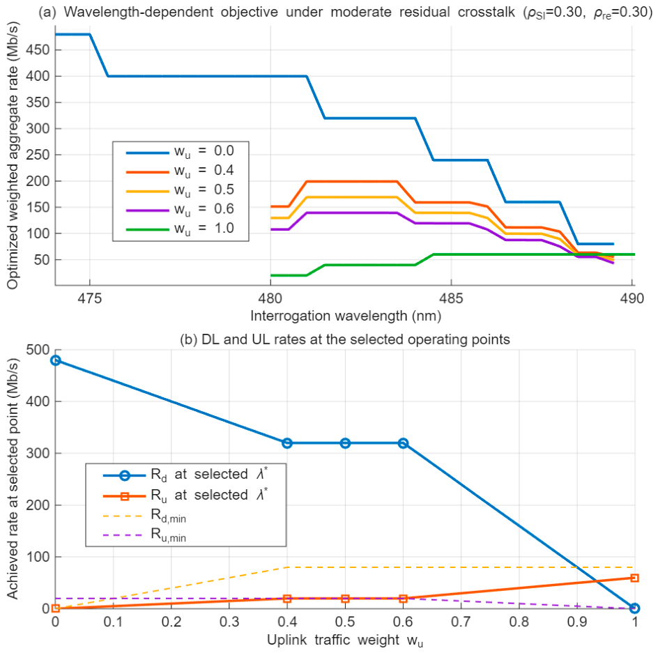
Figure 5 visualizes the traffic-weighted optimization in the wavelength domain. Instead of showing only the final selected wavelength, the figure plots the optimized weighted aggregate rate as a function of interrogation wavelength for several representative uplink traffic weights. For each wavelength, the downlink modulation depth
, uplink modulation depth
, and M-PAM modulation orders are optimized under the FEC BER constraint and the bidirectional service requirements. The objective can be written as:
where
is the uplink traffic weight and
is the downlink traffic weight. In joint-traffic cases, minimum DL and UL service constraints are applied so that the non-dominant direction is not completely sacrificed by the weighted-sum optimization. This is important for the proposed FC-MRR transceiver because even a downlink-dominant operating state still requires uplink acknowledgment, telemetry, beam-control feedback, or channel-state signaling.
Figure 5.
Wavelength-dependent traffic-weighted optimization under moderate residual crosstalk. The optimized weighted aggregate rate is plotted as a function of interrogation wavelength for representative uplink traffic weights and , with and . At each wavelength, , , and the M-PAM modulation orders are optimized under the BER and service constraints. The optimum shifts from the FC absorption-centered region toward the pass-through side as the traffic condition changes from downlink-dominant to uplink-dominant operation.
Figure 5.
Wavelength-dependent traffic-weighted optimization under moderate residual crosstalk. The optimized weighted aggregate rate is plotted as a function of interrogation wavelength for representative uplink traffic weights and , with and . At each wavelength, , , and the M-PAM modulation orders are optimized under the BER and service constraints. The optimum shifts from the FC absorption-centered region toward the pass-through side as the traffic condition changes from downlink-dominant to uplink-dominant operation.
The optimization is evaluated under a moderate residual-crosstalk condition, and , rather than under ideal perfect cancelation. Therefore, the plotted objective reflects a more realistic condition in which the known downlink envelope is not completely removed from the retroreflected uplink signal and return-path light is not perfectly suppressed at the FC downlink receiver. This condition couples wavelength selection and modulation-depth selection: increasing can improve the downlink signal, but it also increases the residual remodulation burden seen by the uplink.
For , the objective is dominated by the downlink rate, and the maximum occurs near the absorption-centered side of the FC spectrum, where the edge-delivered fluorescent power is large. As increases to 0.4 and 0.5, the optimum shifts toward the absorption shoulder. In this region, the FC still absorbs enough optical power for downlink reception, while a sufficient pass-through carrier remains available for MRR-based uplink remodulation. For , the curve favors a slightly longer wavelength because the uplink contribution becomes more important and excessive FC absorption would deplete the MRR carrier. For , the objective is dominated by uplink throughput, and the optimum moves toward the pass-through side, where the interrogation beam primarily functions as the carrier for retroreflective uplink modulation.
The step-like shape of the curves results from adaptive M-PAM rate selection under the FEC BER constraint. As the wavelength changes, the DL and UL SNRs cross the thresholds required for different modulation orders, producing discrete changes in the achievable rate. These discontinuities are therefore not numerical artifacts, but represent practical modulation-format transitions in the adaptive link.
The main conclusion from
Figure 5 is that the proposed FC-MRR module should not be operated at a fixed wavelength for all traffic states. Downlink-dominant operation benefits from wavelengths closer to the FC absorption region, uplink-dominant operation benefits from wavelengths closer to the pass-through region, and balanced bidirectional operation is best supported on the absorption shoulder. This result supports the central concept of spectrally adaptive remodulation: the interrogation wavelength controls the FC/MRR optical power split, while
and
control the downlink envelope strength and uplink remodulation strength under residual-crosstalk constraints.
5.3. Sensitivity to MRR and FC Device Parameters
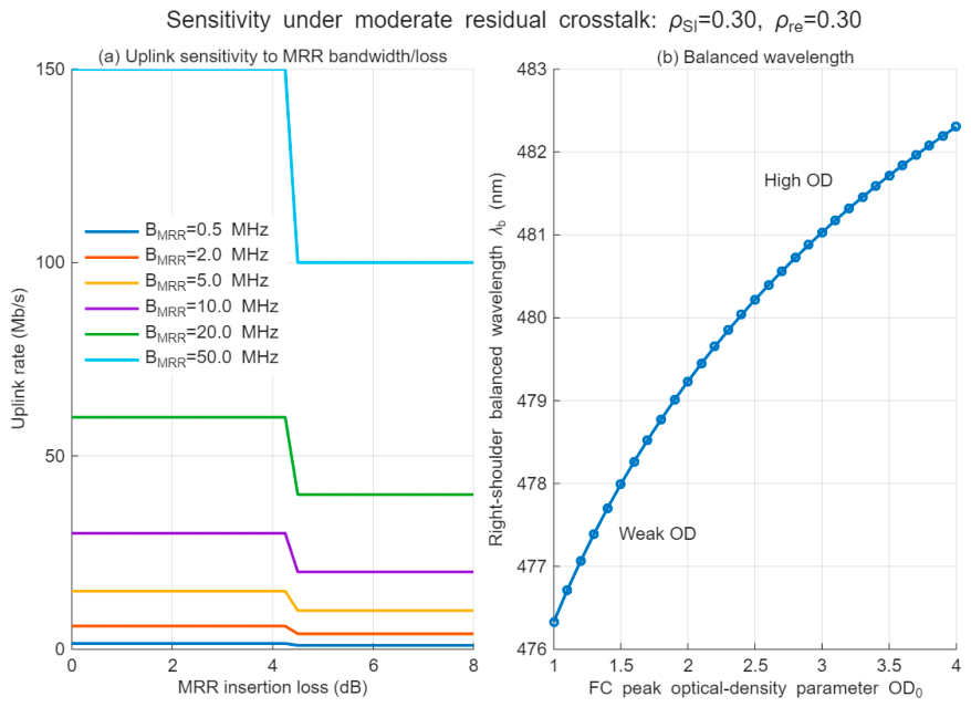
Figure 6 evaluates how the proposed FC-MRR transceiver is affected by two device-level parameters that are critical for practical implementation: the MRR modulation bandwidth/insertion loss, and the FC absorption strength. The analysis is performed under the same moderate residual-crosstalk condition used in the rate-map and traffic-weighted optimization results, with
and
. Thus, the sensitivity study does not represent an ideal perfect-cancelation limit, but rather a more realistic operating condition in which residual uplink self-interference and downlink return-light crosstalk remain after cancelation.
Figure 6a shows the achievable uplink rate as a function of MRR insertion loss for several MRR bandwidths. The result confirms that uplink performance is jointly determined by electrical modulation bandwidth and optical link margin. A larger MRR bandwidth increases the maximum possible symbol rate, but this advantage is useful only when sufficient optical SNR remains after MRR insertion loss and retroreflective round-trip attenuation. Therefore, a high-bandwidth MRR does not automatically guarantee a higher uplink rate. If the insertion loss is too large, the received SNR falls below the threshold required for the corresponding M-PAM order, and the achievable rate drops sharply.
The step-like behavior in
Figure 6a is caused by discrete modulation-order selection under the FEC BER constraint. As the insertion loss increases, the available SNR crosses the threshold for a given M-PAM format, forcing the system to reduce the supported modulation order or the effective data rate. This behavior is practically meaningful: it indicates that MRR design should not be evaluated only by nominal bandwidth. Optical insertion loss, modulation contrast, aperture, drive voltage, and round-trip optical coupling must be considered together. In low-SWaP-C mobile modules, a lower-bandwidth but lower-loss MRR can be preferable to a faster device if the latter requires too much optical power to maintain the required BER.
Figure 6b examines the effect of FC peak optical density
on the balanced operating wavelength. In this panel, the balanced wavelength
is defined on the long-wavelength, pass-through-side shoulder of the FC absorption band. This definition avoids artificial switching between the short- and long-wavelength shoulders and directly captures the operating region most relevant to joint DL/UL remodulation. The balanced point corresponds to the wavelength at which the normalized FC-delivered downlink power and MRR-usable pass-through power become comparable.
As increases, the FC absorbs more strongly and its effective absorption shoulder extends farther toward longer wavelengths. Consequently, the wavelength at which the downlink-delivered power and uplink-usable carrier power are balanced shifts to the right. This monotonic trend is physically expected. A weak FC requires operation closer to the absorption center to provide sufficient downlink signal, whereas a high-OD FC can still deliver useful downlink power at longer wavelengths, allowing more residual carrier to reach the MRR. Therefore, increasing moves the balanced DL/UL operating point toward the pass-through side.
The results in
Figure 6 imply that the FC and MRR must be co-designed rather than optimized independently. Increasing FC optical density improves downlink collection but can reduce the carrier available for MRR remodulation. Reducing FC absorption improves uplink carrier transmission but weakens FC-based downlink reception. Similarly, increasing MRR bandwidth is beneficial only if insertion loss and residual crosstalk do not reduce the SNR below the modulation threshold. The proposed adaptive remodulation framework therefore requires the simultaneous selection of FC optical density, MRR bandwidth/loss, interrogation wavelength, and modulation depths according to the target DL/UL traffic balance.
5.4. Residual Crosstalk Sensitivity and Eye-Diagram Evaluation
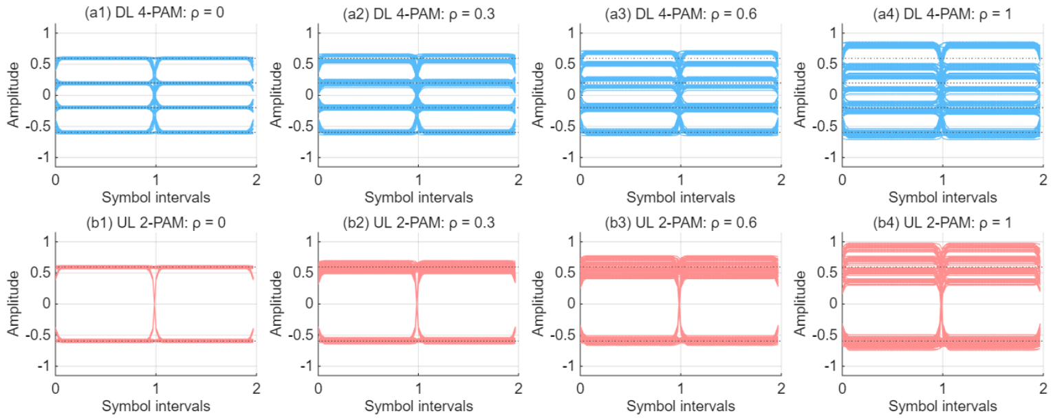
Figure 7 provides a time-domain visualization of how residual crosstalk affects the proposed FC-MRR remodulation transceiver. The previous results quantify achievable rate and operating-point sensitivity, whereas
Figure 7 illustrates the corresponding signal-quality degradation through representative PAM eye diagrams. The purpose of this analysis is not to report experimentally measured eye diagrams, but to show how imperfect cancelation of the remodulation-induced crosstalk terms can degrade the downlink and uplink signal waveforms under a controlled simulation model.
Based on the normalized residual-crosstalk model introduced in
Section 4, representative values of
and 1 are considered, corresponding to ideal cancelation, approximately 5.2 dB of suppression, approximately 2.2 dB, and no cancelation, respectively. In the downlink path, the residual impairment represents uplink return-light coupling into the FC receiver and the associated multiplicative remodulation term. In the uplink path, the residual impairment represents imperfect cancelation of the known downlink envelope at the access point and the remaining downlink-uplink product term. This is consistent with the remodulation model in which the returned signal contains the desired uplink component, the known downlink envelope, and a multiplicative remodulation product.
For clarity, the downlink is shown using 4-PAM, while the uplink is shown using 2-PAM. This choice reflects the asymmetric nature of the proposed module: the FC-based downlink can support a higher-order intensity-modulation format when sufficient absorbed fluorescent power is available, whereas the MRR-based uplink is more conservatively modeled because the retroreflective path is constrained by MRR modulation depth, round-trip loss, and residual self-interference. The same transmitted symbol sequences are used for all residual-crosstalk cases, so the observed differences in eye opening arise from the residual impairment level rather than from different data patterns.
In the perfect-cancelation case, , both the downlink and uplink eye diagrams exhibit clearly separated PAM levels. This represents the ideal case in which the access point fully removes the known downlink-envelope component from the uplink return and the mobile-side receiver experiences no residual return-light coupling. As increases to 0.3, the eye openings remain distinguishable, but the PAM levels begin to broaden. This moderate case represents a practical operating condition in which the main crosstalk components are reduced but not eliminated.
For , the degradation becomes more pronounced. The downlink 4-PAM levels show increased vertical spreading, and the uplink 2-PAM eye becomes less clean because residual downlink-envelope leakage and multiplicative remodulation distortion remain after cancelation. In the worst case, , the residual crosstalk is not effectively removed. The resulting eye diagrams show strong level spreading and reduced decision margin, indicating that reliable detection would require either lower-order modulation, increased pilot/cancelation overhead, reduced modulation depth, or a shifted interrogation wavelength.
These results support the need for the bidirectional crosstalk-aware adaptation algorithm described in
Section 4. In the uplink, the access point can exploit its local knowledge of the transmitted downlink waveform to suppress the known-envelope component before uplink detection. In the downlink, the mobile module can use the known MRR drive state and pilot-based coupling estimates to reduce return-light crosstalk coupled into the FC receiver. However,
Figure 7 shows that cancelation should not be assumed to be perfect. The residual terms must be treated as measurable impairment parameters and included in the operating-point selection.
Therefore, the practical role of the proposed adaptive scheme is not only to choose a wavelength that balances FC absorption and MRR pass-through power, but also to maintain acceptable signal quality under imperfect cancelation. If the residual crosstalk increases, the controller can shift the interrogation wavelength, reduce
or
, select a more robust PAM order, or increase pilot-assisted cancelation overhead.
Figure 7 thus complements the rate-map and optimization results by showing the waveform-level consequence of residual crosstalk in the proposed bidirectional FC-MRR transceiver.
5.5. Design Implications for Low-SWaP-C Mobile OWC Modules
The numerical results support the central claim of this work: an FC and an MRR can be combined into a compact bidirectional OWC module whose operating mode is controlled spectrally and electronically by the infrastructure, so that the mobile side remains compact and low power while the access point supplies the tunable interrogation beam, receiver aperture, tracking, and signal processing. The module is most useful for asymmetric mobile links such as drones, robots, and distributed sensor units, which require robust downlink commands and control data but whose uplink traffic consists largely of acknowledgments, telemetry, and alignment feedback, and for which a fully symmetric active transceiver would be unnecessarily large and power-consuming.
The main limitations before deployment are that the optimum wavelength depends on the actual FC spectrum and optical density, that the achievable uplink rate depends strongly on MRR insertion loss, bandwidth, and round-trip margin, and that residual crosstalk cannot be neglected in the balanced mode. Experimental validation should therefore integrate an active MRR device, measure the residual coefficients under realistic conditions, and verify the cancelation loop end-to-end.
Beyond the hardware configuration, the numerical results follow from a structural property of the FC transfer model. Defining the pass-through transmittance as
Equations (3) and (4) yield the complementarity relation:
so the downlink and uplink power shares cannot be assigned independently. A second coupling acts in the temporal domain, since Equations (10) and (18) show that the retroreflected uplink carries the downlink envelope and the residual self-interference of Equation (22) grows as
, unlike conventional bidirectional OWC in which the two directions occupy orthogonal resources.
Because the two couplings act in opposite directions, neither extreme of the FC spectrum is optimal under bidirectional traffic, as seen in
Figure 5, where the balanced-traffic optimum lies on the absorption shoulder and migrates toward the pass-through side as
increases. Conventional FC-only and MRR-only architectures correspond to the two endpoints of this locus, at the absorption peak with
and in the pass-through window with
, so the formulation generalizes them rather than concatenating them. Since Equation (32) depends only on the spectral overlap and the traffic weights, the methodology applies to any wavelength-selective absorbing receiver operated with a passive optical remodulator.
Because the fading factors of Equation (19) are set to their mean values in the rate results above, these represent short-range or controlled deployments: laboratory demonstrations, indoor links, factory automation, and infrastructure-assisted links to hovering or slowly moving platforms within a stabilized pointing envelope. When these factors are active, as in free-flight UAV links, they contract the achievable rates without altering the spectral power-partitioning relation of Equation (32) on which the present conclusions rest; their asymmetric effect on the operating point is discussed in
Section 5.6.
Table 3 benchmarks the proposed framework against four representative architectures: conventional bidirectional FSO, MRR-based, FC-based, and visible-light backscatter systems. Since these have been demonstrated under different operating conditions, link budgets, and experimental assumptions, the comparison is made at the level of system architecture rather than absolute performance, covering the communication principle, the mobile-side hardware, the bidirectional capability, and the degree of adaptive resource control.
Each existing architecture is well suited to a specific class of scenarios but is constrained in at least one of three respects: mobile-side hardware complexity, communication flexibility, or bidirectional capability. Conventional bidirectional FSO achieves the highest throughput and reach but requires an onboard laser source and a pointing subsystem that dominate the mobile-side SWaP-C budget; MRR-based systems eliminate the mobile laser but rely on a small-aperture photodetector for downlink and offer no wavelength-adaptive control; FC-based systems improve downlink collection but provide no uplink; and visible-light backscatter achieves ultra-low-power operation at the expense of range, rate, and adaptability. The proposed framework instead serves both directions from a single interrogation beam while the mobile terminal retains a passive optical front end. As noted above, however, the MRR-based and FC-based architectures are limiting cases rather than independent alternatives; the comparison therefore indicates not that the framework outperforms them under all conditions, but that it subsumes them while providing the intermediate operating points required for asymmetric traffic.
5.6. Practical Deployment Considerations
The initial interrogation wavelength follows directly from the FC absorption spectrum without a search: from Equation (32), the absorbed and pass-through fractions become equal when
. For the Gaussian optical-density model of
Section 3, the long-wavelength solution is:
defined whenever
. Equation (33) depends only on the absorption-center wavelength, the absorption width, and the peak optical density, all obtainable from a single transmission measurement of the FC plate, and it reproduces the monotonic trend of
Figure 6b. A downlink-dominant service is initialized near
, an uplink-dominant service in the pass-through window, and a balanced service at
, after which the loop of
Figure 3 refines the operating point; since the FC spectrum is a material property, this calibration is needed only once at commissioning. The residual gain and crosstalk coefficients are a small set of parameters that vary primarily on the timescale of platform motion rather than at the symbol rate. As a representative example, for a 20-Msymbol/s uplink and a 10 ms coherence interval, a pilot block of 1000 symbols corresponds to an overhead of 0.5%. Under more rapid motion, the pilot density can be increased at the expense of payload rate or modulation order.
Considering the practical constraints, the uplink distance can be approximately ~100 m, while the downlink remains theoretically usable to approximately ~400 m under the same constraints because of its slower SNR decay. The effective bidirectional link distance set by the MRR uplink is therefore approximately ~100 m under the moderate outdoor conditions considered here. The operating band is set by the FC absorption spectrum rather than chosen for propagation, and 400–550 nm is not a classical low-attenuation FSO window. Molecular scattering scales as
, so the attenuation coefficient at 400 nm is about three times that at 550 nm, but in absolute terms clear-air molecular attenuation is of order 0.05 to 0.2 dB/km and is negligible over the short-range regime above, while under haze or fog the dominant aerosol scattering is nearly wavelength-independent across the visible band [
5,
24,
40,
41]. Atmospheric attenuation therefore acts as an almost common-mode loss: it reduces the link margin and hence the range, but leaves
and
, which vary by orders of magnitude over the same interval, as the quantities that set the optimum wavelength. The more significant penalty of visible-band operation is daytime solar background, for which the Stokes shift provides inherent discrimination since the FC receiver filters at the emission band. Since Equation (32) depends only on the absorption and pass-through spectra, the same formulation applies to an FC absorbing in a more favorable window.