


Abstract
A high-stability actively mode-locked fiber laser (AMLFL) is proposed and experimentally demonstrated. This AMLFL is based on a distributed feedback laser diode (DFB-LD) injection locking with Fabry-Perot (F-P) etalon frequency stabilization. In this system, a wavelength modulation method is employed to generate the feedback signal for frequency stabilization. The stabilization mechanism utilizes the linear response characteristic of the first-order derivative of the F-P etalon transmission peak. This achieves wavelength stabilization of the DFB-LD. Subsequently, the stabilized light source is injected into the ring cavity of the AMLFL. The proposed system does not require modification to the existing AMLFL cavity. It also features a simple structure and low implementation cost. Experimental results show that, with frequency stabilization, the wavelength drift of a selected spectral line is reduced to within the 10 pm resolution of the OSA. Meanwhile, the standard deviations of the 5 GHz spectral component power fluctuation and the average output optical pulse power are 0.01 dB and 0.01 dB, respectively.
1. Introduction
Fiber lasers utilize optical fibers as the gain medium and offer advantages such as strong immunity to interference, high output power, high efficiency and high stability [1,2,3]. As an important class of fiber lasers, harmonic mode-locked fiber lasers (MLFLs) can generate ultrashort pulses with narrow pulse widths, high peak powers, and broad optical spectra [4,5], making them attractive for applications in precision manufacturing [6], biomedical applications [7] and quantum communication [8]. Therefore, MLFLs have become an active area of research. In particular, harmonic mode-locked fiber lasers are widely used to generate high-repetition-rate pulse trains by operating at a harmonic of the fundamental cavity repetition frequency. The actively mode-locked fiber laser (AMLFL) investigated in this work operates in such a harmonic mode-locking regime.
MLFLs are generally classified into passive and active mode-locking schemes [9,10,11,12]. Passive mode locking is achieved by incorporating a saturable absorber [13,14]. This category includes natural saturable absorbers based on the intrinsic absorption properties of materials, as well as artificial saturable absorbers based on nonlinear optical effects. However, conventional passively mode-locked fiber lasers are usually limited in fundamental repetition rate by the cavity length and do not provide direct electronic synchronization to an external radio frequency (RF) clock without additional feedback control [15]. In contrast, an AMLFL employs an external RF signal to drive an electro-optic modulator, which imposes periodic amplitude or phase modulation on the optical field inside the cavity [16,17]. When the modulation frequency matches an integer multiple of the fundamental cavity repetition frequency, harmonic mode locking can be achieved, enabling the generation of stable high-repetition-rate pulse trains. In ref. [18], the range of the repetition rate was continuously tunable from 2 GHz to 6 GHz. At the repetition rate of 2.5 GHz, pulse-width tuning from 4 ps to 30 ps was demonstrated. Zhang et al. [19] demonstrated a broadband III–V/thin-film lithium niobate AMLFL. The experimental results showed a stable broadband frequency comb spanning 45 nm. This comb had a 10-dB spectral bandwidth of 19.1 nm. Its mode-locking beat-note signal-to-noise ratio (SNR) exceeded 60 dB. In ref. [20], an actively mode-locked all-fiber laser capable of switching among multiple transverse modes was demonstrated. The temporal pulse train exhibited a pulse spacing of 129.70 ns, corresponding to a repetition rate of 7.71 MHz, and the corresponding RF spectrum showed an SNR of 73.58 dB.
In order to better improve the output stability of AMLFLs, there are broadly two main classes. The first approach employs active feedback control of the cavity length, thereby achieving output stability of the AMLFL. P. Yan et al. [21] employed a phase-locked loop (PLL) structure to feedback-control the pump power of the pump laser, thereby changing the nonlinear refractive index of the erbium-doped fiber and enabling cavity-length control of the laser cavity. As a result, repetition-rate stabilization was achieved over 1 h. In ref. [22], a highly vibration-resistant all-polarization-maintaining fiber design was adopted, and the free-running MLFL exhibited a long-term repetition-rate stability. R. Pan et al. [23] reported a fiber actuator composed of a piezoelectric transducer and a ring-type displacement amplifier. Experimental results showed that the laser repetition rate reached a fractional stability over a 24-h observation duration. The second method utilizes injection locking to achieve output stability of the AMLFL. In ref. [24], V. Billault et al. designed a scheme using injection locking to suppress supermode noise and maintain the output stability of an AMLFL. The RF spectral rejection of the supermode spur exceeded 140 dBc/Hz. K. Krzempek [25] proposed a system which injected the nanosecond 1.55 µm master oscillator pulses into the slave cavity of the dissipative soliton resonance laser to induce the cross-phase modulation effect, thereby automatically compensating for cavity-length drift.
However, quantitative analysis of the long-term wavelength and power stability of AMLFLs remains insufficient. Despite these advances, some drawbacks remain in existing AMLFL systems. First, there is a lack of quantitative analysis before and after external optical injection, particularly regarding long-term stability. Second, as the design of the feedback loop becomes increasingly complex, the demands on feedback technology become higher, and the cost also increases. Therefore, exploring more efficient and economical wavelength stabilization schemes for AMLFLs is necessary.
In this paper, we propose and experimentally demonstrate a high-stability AMLFL based on distributed feedback laser diode (DFB-LD) injection locking with Fabry-Perot (F-P) etalon frequency stabilization. In the system, frequency stabilization of the DFB-LD is first achieved by employing a wavelength modulation method, where the linear response characteristic of the first-order derivative of the F-P etalon transmission peak is utilized to generate the feedback signal. Subsequently, the stabilized DFB-LD is injected into the ring cavity of the AMLFL. Finally, wavelength-stabilized mode locking is realized. Experimental results demonstrate that after adopting the frequency-stabilized injection scheme, the wavelength drift of a selected spectral line in the AMLFL output is reduced to within the 10 pm resolution of the OSA. In addition, the SD of the power fluctuation of the 5 GHz spectral component is 0.01 dB, and the SD of the average power of the output optical pulse is 0.01 dB. This approach requires no changes to the original main ring cavity of the AMLFL, thereby maintaining a low cost and a simple configuration.
2. Operation Principles
2.1. Free-Running Active Mode-Locking
When an AMLFL operates in a steady state, the frequency spacing between longitudinal modes within the gain bandwidth of the gain medium is related to the cavity length and the refractive index of the intracavity medium. Assuming an optical resonant ring cavity with a length of , the longitudinal mode spacing and the frequency of longitudinal modes can be expressed as
where c is the speed of light in vacuum, is the refractive index, and N is a positive integer. For simplicity, a symmetric set of longitudinal modes around the center frequency is considered. The zeroth-order mode is selected as the central longitudinal mode, and K modes are assumed on each side of it. Therefore, a total of longitudinal modes are considered to oscillate together in the cavity. The output optical field of the AMLFL is expressed as:
where , and represent the amplitude, angular frequency, and initial phase of the k-th longitudinal mode, respectively. The condition for mode locking is that the phases of all longitudinal modes are synchronized, with a fixed constant phase difference between any two adjacent longitudinal modes, that is, . This phase relationship implies that . is the phase of the zeroth-order longitudinal mode of the mode-locked laser. The angular frequency can be expressed as . is the center angular frequency of the AMLFL, that is, the angular frequency of the zeroth-order longitudinal mode. For analytical simplicity, an idealized equal-amplitude approximation is adopted here. In practice, the amplitudes of different longitudinal modes may vary due to the finite gain bandwidth, intracavity loss, and spectral filtering. Under this approximation, the amplitudes of all longitudinal modes are denoted as , and the output optical field of the AMLFL can be written as
Then, the total optical intensity can be given by
It should be noted that the equal-amplitude approximation is used only to obtain a compact analytical expression. Unequal modal amplitudes would modify the detailed temporal pulse envelope, but they do not change the basic conclusion that stable mode locking requires fixed phase relationships among the longitudinal modes. From Equations (3) and (4), it can be seen that the output optical field and optical intensity of an AMLFL are related to and . Due to environmental factors such as mechanical vibration and temperature drift, and may change, potentially leading to mode unlocking. Therefore, it is necessary to study an AMLFL with stable wavelength.
2.2. Frequency-Stabilized Injection Light
To address the wavelength drift, a frequency-stabilized DFB-LD based on the F-P etalon is proposed. In this work, the F-P etalon is modeled as an ideal plane-parallel etalon consisting of two parallel reflecting surfaces. Under this plane-parallel approximation, the normalized transmittance of the F-P etalon can be described by the standard Airy function as follows [26]:
where R is the power reflectivity of the reflecting surfaces, is the refractive index of the medium inside the cavity, is the cavity length, and is the angular frequency of the incident light. As an example, considering the center frequency of a transmission peak of the F-P etalon, it satisfies
where N is an integer. Taking the first derivative of Equation (5) with respect to yields the frequency discrimination curve:
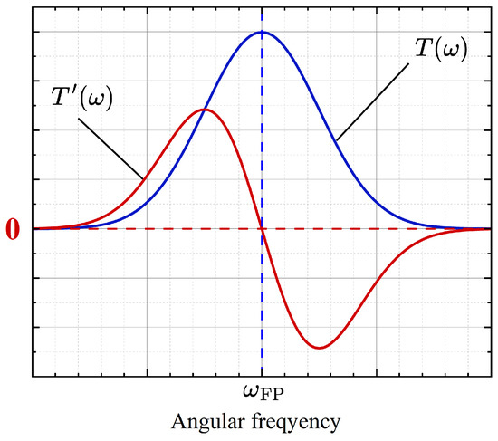
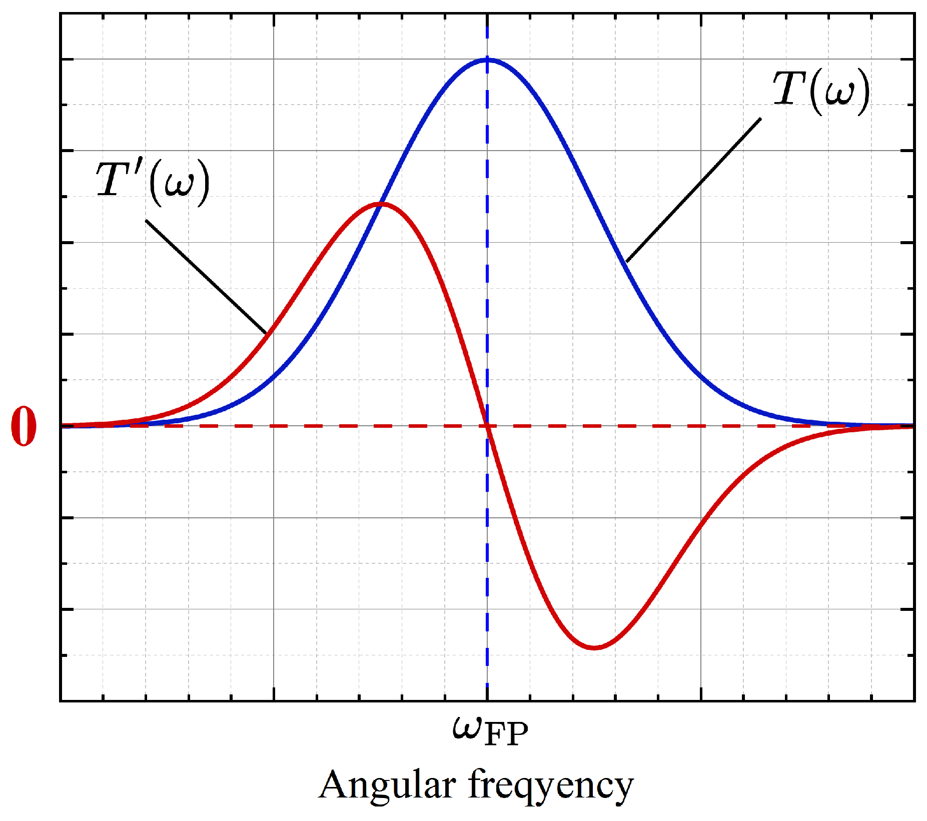
Near the center of a transmission peak, the term is very small, and is approximately linear. Figure 1 shows the transmission spectrum and the first-order differential curve of the F-P etalon. The blue line represents the transmission peak of the F-P etalon, and the red line represents its first-order differential curve.
Figure 1.
Schematic diagram of the transmission spectrum and the first-order differential curve of the F-P etalon.
It can be seen from Figure 1 that the first-order differential curve is approximately linear in the vicinity of the center frequency of the transmission peak. When the angular frequency of the DFB-LD is higher than the center angular frequency of the transmission peak , the first-order differential is negative. When , the first-order differential is positive. The sign of indicates the direction of deviation of the DFB-LD frequency from the transmission peak, which enables frequency discrimination.
To obtain the feedback signal, a small sinusoidal modulation is applied to the driving current of the DFB-LD, causing its output angular frequency to vary sinusoidally around the center value :
where is the modulation amplitude and is the modulation angular frequency. The modulated DFB-LD passes through the F-P etalon, and the transmitted optical intensity is given by . By expanding in a Taylor series around , we obtain:
The photodetector (PD) converts light intensity into an electrical signal, which is then mixed with a local oscillator signal . After passing through a low-pass filter to remove high-frequency components, the resulting direct current (DC) component of the mixed signal serves as the feedback signal:
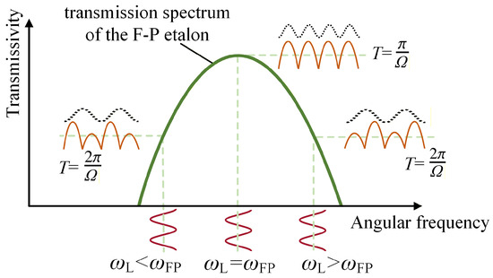
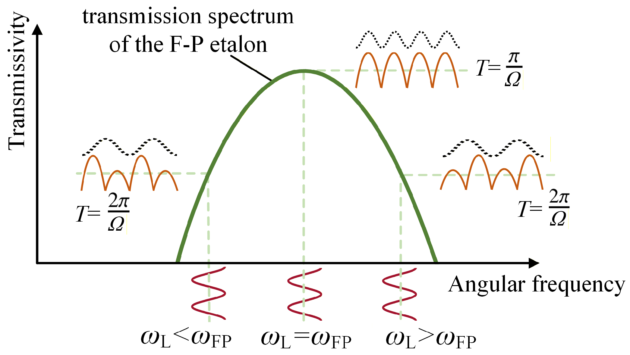
From Equation (10), it can be seen that when , and ; when , and ; when , and . The corresponding process is illustrated in Figure 2. When the center wavelength exactly coincides with the peak of the transmission spectrum, the wavelength modulation at angular frequency produces an output signal with an angular repetition frequency of 2, and the feedback DC signal is zero. When the center wavelength deviates from the transmission peak, the output signal exhibits an angular repetition frequency of 2, while the feedback DC signal becomes non-zero. In this way, after obtaining the DC signal, the driving current of the DFB-LD is feedback-controlled according to its magnitude, so that the feedback DC signal approaches zero, thereby achieving frequency stabilization of the DFB-LD.
Figure 2.
Schematic of the demodulation signal obtained after the DFB-LD passes through the transmission peak of the F-P etalon.
3. Experimental Setup
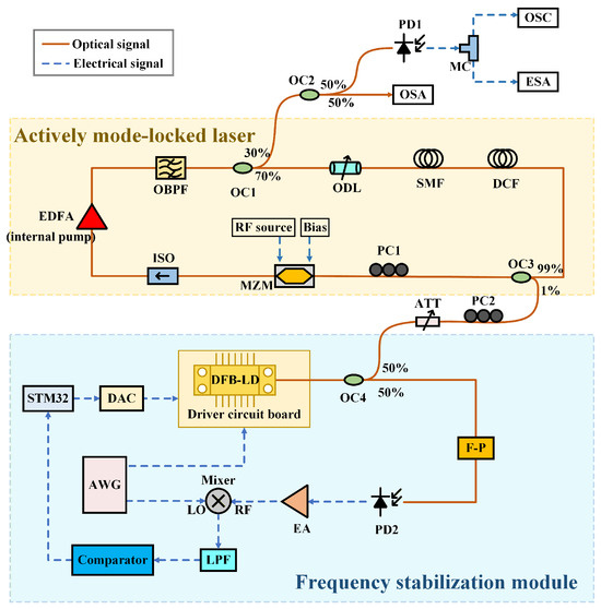
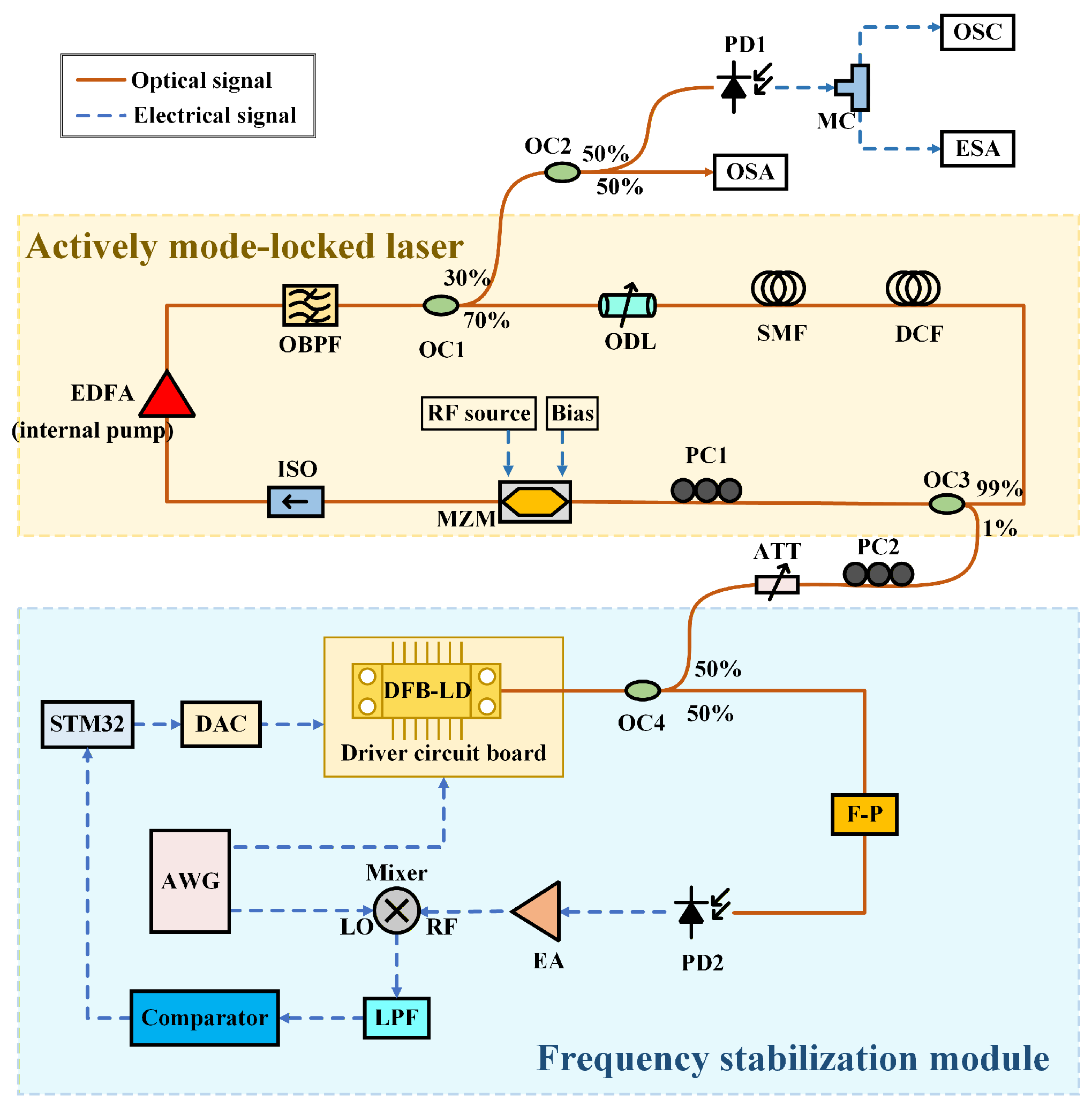
The schematic diagram of the high-stability AMLFL based on DFB-LD injection locking with F-P frequency stabilization is shown in Figure 3. It mainly consists of two sections: the AMLFL and the F-P frequency stabilization module. In the AMLFL, an erbium-doped fiber amplifier (EDFA, EDFA-MD-L-30-FC/UPC, Wuhan Post and Telecommunications Research Institute, Wuhan, China) is used as the gain module. The EDFA is a commercial module with an internal pump laser diode. Therefore, no additional external pump optical path is required in the ring cavity. It provides a broadband-amplified optical field and simultaneously amplifies the intracavity optical signal. During the experiments, no adjustment is made to the EDFA operating setting. An optical band-pass filter (OBPF, BVF-200CL, Alnair Laboratories Corporation, Tokyo, Japan) with a center wavelength of 1550 nm and a 3-dB bandwidth of 3 nm is used. Through a 3:7 optical coupler (OC1), 30% of the optical field is extracted from the cavity as the output. This output is split into two parts by a 5:5 OC2. One part is connected to an optical spectrum analyzer (OSA, OSA-AP1, APEX Technologies, Tokyo, Japan), while the other part is converted into an electrical signal by PD1 (DSC40S, 16 GHz, Discovery Semiconductors, Inc., Ewing, NJ, USA), and its time-domain waveform and frequency-domain electrical spectrum are observed using an oscilloscope (OSC, 86100A, Agilent Technologies, Santa Clara, CA, USA, >50 GHz bandwidth) and an electrical spectrum analyzer (ESA, 8564EC, Agilent Technologies, Santa Clara, 9 kHz–40 GHz), respectively. The remaining 70% of the optical field continues circulating within the ring cavity. An optical delay line (ODL, manual variable optical delay line, VDL-001, General Photonics Corp., Chino, CA, USA) precisely and controllably delays the AMLFL pulses in time, thereby fine-tuning the ring cavity length to satisfy the mode-locking condition. After propagating through the single-mode fiber (SMF, G.652.D, Yangtze Optical Fibre and Cable Joint Stock Limited Company, Wuhan, China), the optical field enters the dispersion-compensating fiber (DCF, DM1013-A, Yangtze Optical Fibre and Cable Joint Stock Limited Company, Wuhan, China). The DCF is used to adjust the intracavity dispersion, balancing the normal and anomalous dispersion to compensate for pulse-broadening effects. A 5-GHz microwave signal generated by an RF source is used as the modulation signal for the Mach–Zehnder modulator (MZM, AM40, Fiber-Resources, Zhuhai, China), which is biased at the quadrature point. Since the MZM is polarization-sensitive, a polarization controller (PC1) is placed before it to ensure stable polarization of the input optical field. An isolator (ISO) ensures unidirectional propagation of the optical field within the cavity, thereby preventing back-reflection crosstalk. Finally, the optical field returns to the EDFA, completing the optical resonant loop.
Figure 3.
Schematic diagram of the high-stability AMLFL based on DFB-LD injection locking with F-P frequency stabilization. EDFA: erbium-doped fiber amplifier, OBPF: optical band pass filter, OC: optical coupler, ODL: optical delay line, PD: photodetector, SMF: single-mode fiber, DCF: dispersion-compensating fiber, PC: polarization controller, MZM: Mach–Zehnder modulator, ISO: isolator, EA: electrical amplifier, LPF: low-pass filter, DAC: digital-to-analog converter, DFB-LD: distributed feedback laser diode, F-P etalon: Fabry-Perot etalon, AWG: arbitrary waveform generator, ATT: optical attenuator, OSC: oscilloscope, OSA: optical spectrum analyzer, ESA: electrical spectrum analyzer, MC: microwave coupler.
In the frequency stabilization module, the driving current of the butterfly packaged DFB-LD (BFLD-CH35-20PM-FA) is provided by a driver circuit board. The output light from the DFB-LD passes through an OC4 (5:5), where 50% of the optical field is extracted as the frequency-stabilized output. The remaining 50% is directed into the F-P etalon and subsequently received by a PD2 (DSC40S, 16 GHz). The resulting electrical signal from PD2 contains a 12 MHz fundamental component related to the frequency deviation of the DFB-LD from the F-P transmission peak. This signal is amplified and fed into the RF port of a frequency mixer. One channel of an arbitrary waveform generator (AWG, RIGOL DG1062Z) generates a 12 MHz electrical signal to modulate the driving current of the DFB-LD via the driver circuit board. Another synchronized 12 MHz electrical signal is fed into the LO port of the frequency mixer. After low-pass filtering, the mixed signal produces a DC component that is used as the feedback DC signal for frequency stabilization. The feedback DC signal is further sent to a voltage comparator (ADCMP602). The comparator compares the DC feedback voltage with a preset threshold voltage and outputs a high or low logic level to the STM32 microcontroller. It should be noted that the comparator does not use an independent reference-frequency source. The 12 MHz frequency reference for demodulation is provided by the AWG. Ideally, the feedback DC voltage is 0 mV when the DFB-LD wavelength coincides with the F-P etalon transmission peak. In the experiment, the threshold voltage is set to 1 mV to avoid false triggering caused by residual electrical noise and DC offset. This feedback DC signal is further processed by a comparator and then sent to an STM32 microcontroller, which generates a feedback control signal under software control. The control signal is converted through a digital-to-analog converter (DAC) module and applied to the DFB-LD driver circuit board to achieve frequency stabilization of the DFB-LD. To adjust the optical power of the injected light, the frequency-stabilized DFB-LD output passes through an optical attenuator (ATT). Additionally, PC2 is employed to match the polarization state of the injected light with that of the ring cavity. Finally, the frequency-stabilized DFB-LD output is injected into the ring cavity through the 1% port of an OC3.
4. Experimental Results
4.1. Frequency Stabilization
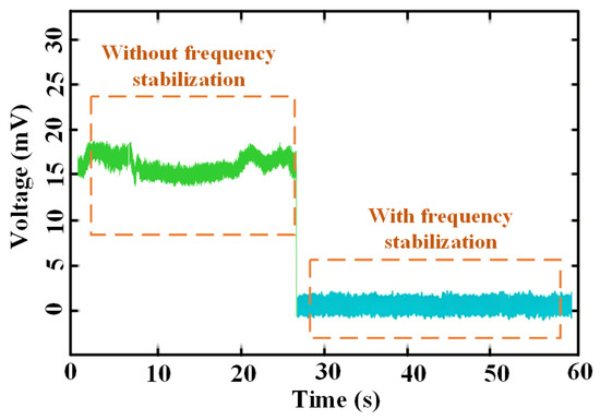
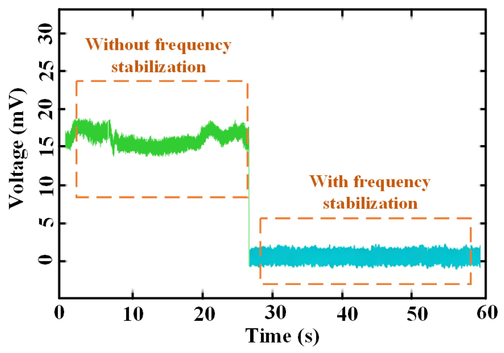
First, experiments on the frequency stabilization module are carried out. With frequency stabilization control activated, the feedback DC signal is compared with the threshold voltage of the comparator. If the feedback DC signal exceeds the threshold, a high-level output is generated. Conversely, when the feedback DC signal falls below the threshold, a low-level output is produced. Figure 4 shows the feedback DC signal with and without frequency stabilization control. The green curve represents the free-running condition of the DFB-LD, which manifests as irregular fluctuations in the feedback DC signal. The blue curve corresponds to the feedback DC signal under frequency stabilization control. It can be seen that the feedback DC signal remains stable, indicating that frequency stabilization has been achieved. The stepwise variation under frequency stabilization results from the discrete DAC control of the DFB-LD driving current, indicating that the feedback loop drives the DFB-LD frequency toward the F-P etalon transmission peak and finally locks it near the zero-feedback point.
Figure 4.
Voltage variation curve of the feedback DC signal with and without frequency stabilization control.
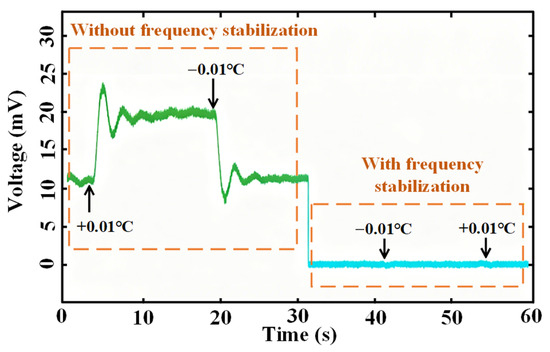
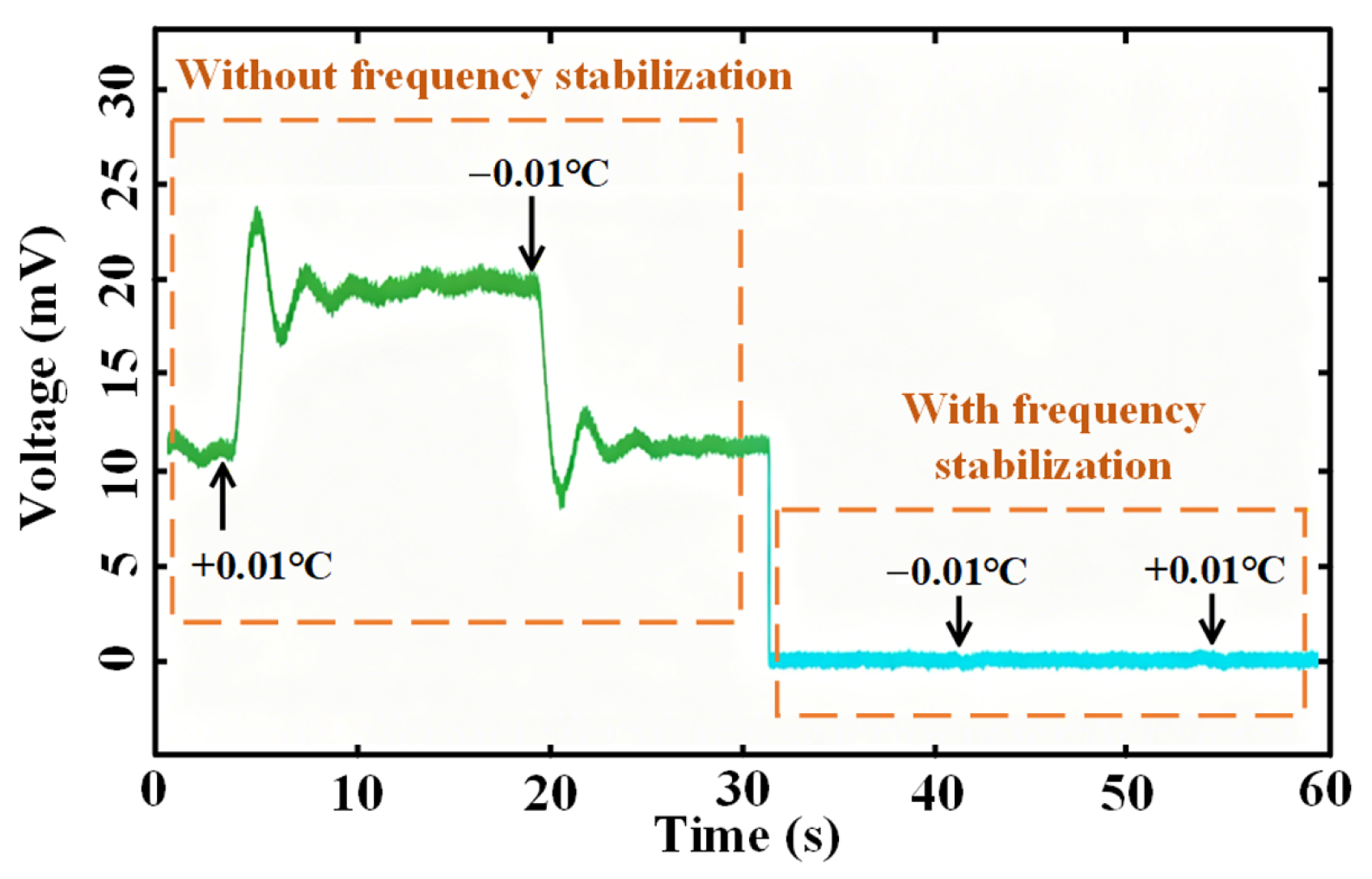
To further evaluate the stability of the frequency stabilization module, the operating temperature of the DFB-LD is manually varied to observe the corresponding feedback DC signal. The experimental results are shown in Figure 5. The operating temperature of the DFB-LD is tuned up and down by 0.01 °C under both free-running and frequency-stabilized conditions. It can be observed that without frequency stabilization control, the feedback DC signal exhibits significant fluctuations. With frequency stabilization control, the feedback DC signal is rapidly regulated to approximately 0 mV even when the operating temperature varies, demonstrating effective suppression of temperature-induced frequency drift.
Figure 5.
Voltage variation curve of the feedback DC signal when adjusting the temperature with and without frequency stabilization control.
4.2. Free-Running AMLFL
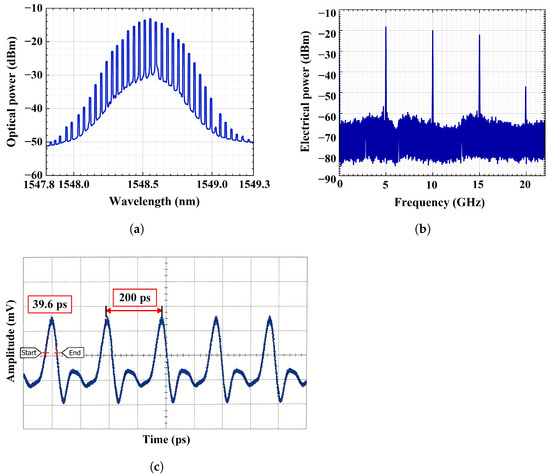
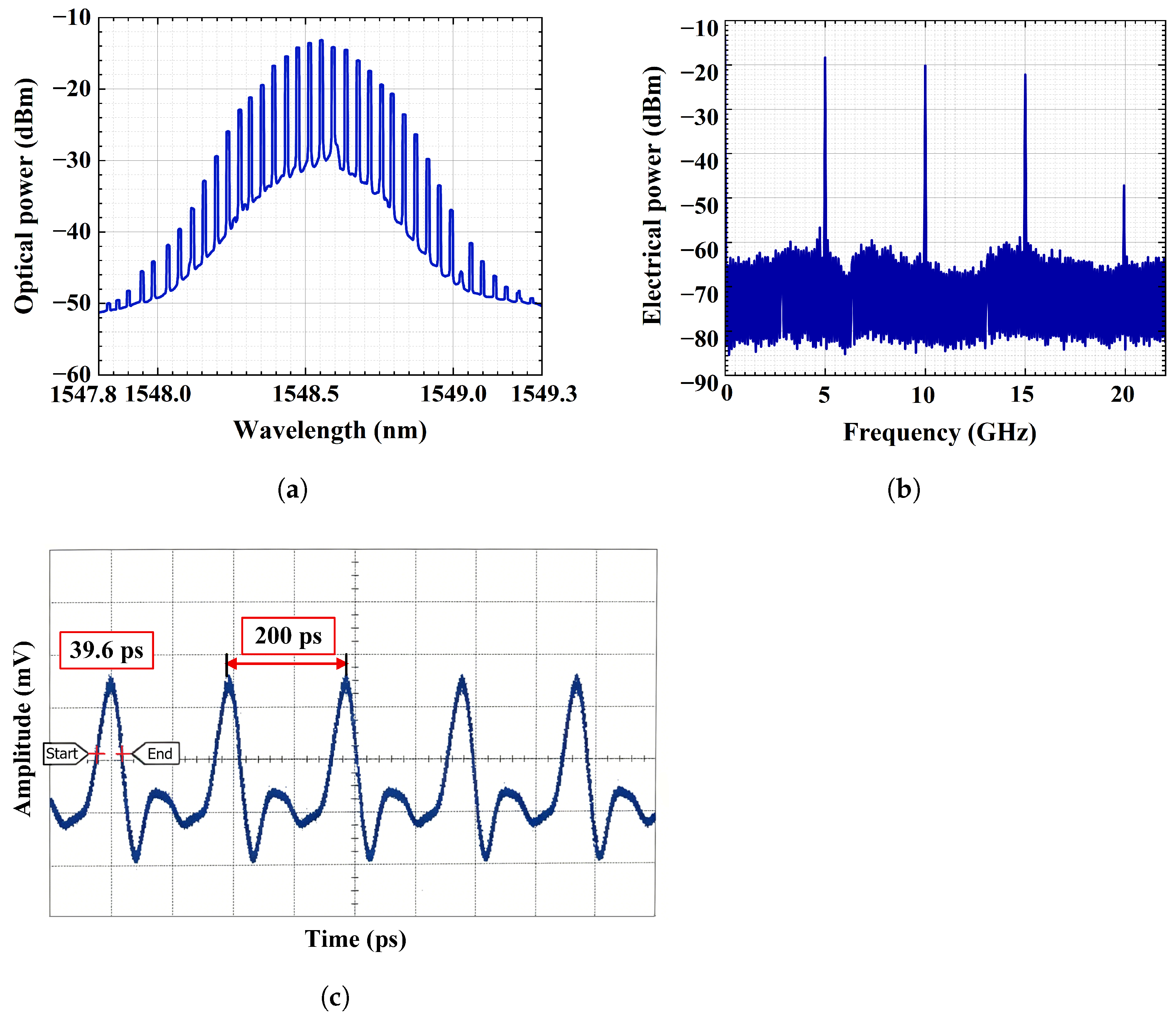
When the 1% port of OC3 is disconnected, the system operates as a free-running AMLFL. To obtain a clear and stable time-domain waveform, the ODL is manually tuned to adjust the cavity length until 5 GHz RF modulation frequency applied to the MZM matches a high-order harmonic of the fundamental cavity repetition frequency of the AMLFL. At this point, the measured optical spectrum is shown in Figure 6a. It can be seen that the center wavelength of the spectrum is approximately 1548.55 nm. Harmonics of the repetition rate within a 22 GHz span are displayed in Figure 6b. The RF spectrum shows a 5 GHz harmonic repetition component, which is consistent with the RF modulation frequency applied to the MZM. The weakening of the 4th harmonic around 20 GHz is mainly caused by the finite pulse width of the pulse train and the non-flat high-frequency response of the electrical detection chain. It should be noted that the RF spectrum is plotted over a wide frequency span to show the 5 GHz repetition component and its harmonics. Therefore, the supermode sidebands close to the main harmonic components are not clearly resolved in this display scale, which does not imply the complete absence of supermode noise. Moreover, by observing the detailed RF spectrum around the 5 GHz component, the spacing between adjacent side modes is measured to be approximately 1.7 MHz, which corresponds to the fundamental cavity repetition frequency of the AMLFL. Figure 6c presents the corresponding time-domain waveform. The oscilloscope-measured temporal pulse width is observed to be 39.6 ps. Meanwhile, the repetition rate is 5 GHz.
Figure 6.
Experimental results of the free-running AMLFL. (a) The measured optical spectrum. (b) The measured RF spectrum. (c) The corresponding time-domain waveform.
4.3. Injection into the AMLFL Without Frequency Stabilization
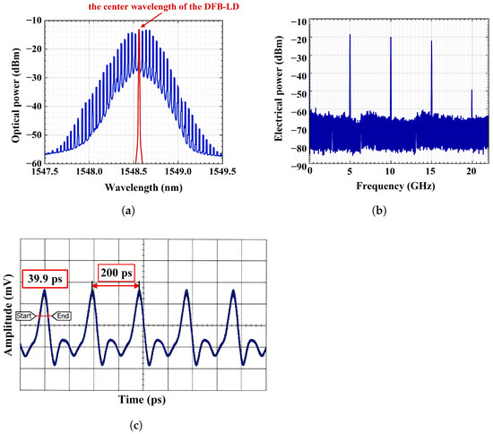
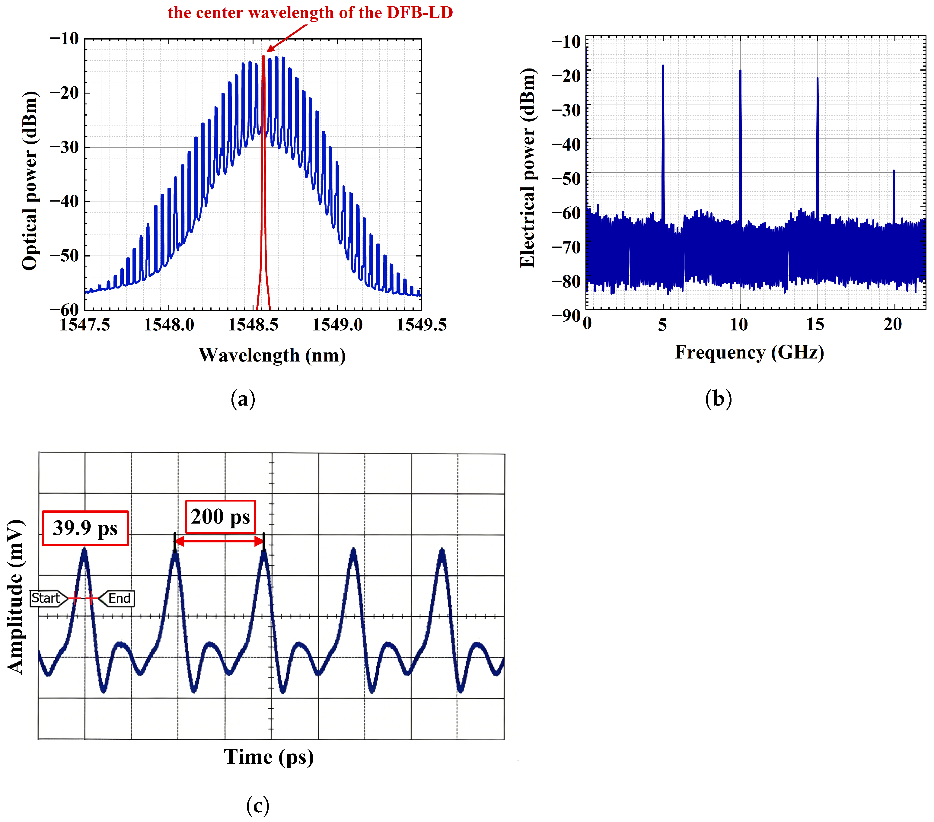
The 1% port of OC3 is connected to the system, with the injection light source provided by the DFB-LD without frequency stabilization. The driving current of the DFB-LD is adjusted so that its center wavelength roughly aligns with the center wavelength of the AMLFL. In addition, it is experimentally observed that an excessively high injection power may disturb the intracavity balance and lead to waveform distortion or unstable mode-locking operation, while an excessively low injection power may weaken the stabilizing effect. Therefore, the injection power used in this experiment is selected as −20.96 dBm, at which stable mode-locked operation and improved long-term stability are obtained. To evaluate the output characteristics of the system, the optical output signals are measured and recorded. The measured optical spectrum is shown in Figure 7a. The red curve shows the center wavelength of the DFB-LD. The center wavelength of the AMLFL is approximately 1548.55 nm. In this case, the center wavelength of the DFB-LD is set to match that of the AMLFL, which is 1548.55 nm. The output optical power of the DFB-LD is 10.31 dBm, and its linewidth is 5 MHz. The spectrum shows that the injection into the AMLFL without frequency stabilization exhibits a longitudinal mode spacing of 0.04 nm, which corresponds to a pulse repetition frequency of 5 GHz. The electrical spectrum of the AMLFL is shown in Figure 7b. The corresponding time-domain waveform is shown in Figure 7c. The zoomed-in view of Figure 7c shows that the oscilloscope-measured temporal pulse width is 39.9 ps. Injection into the AMLFL without frequency stabilization mainly enhances long-term frequency stability, reduces timing jitter, and improves repetition-rate accuracy, rather than modifying the temporal pulse profile. Consequently, the oscilloscope-measured temporal pulse width changes only slightly.
Figure 7.
Experimental results of injection into the AMLFL without frequency stabilization. (a) The measured optical spectrum. (b) The measured RF spectrum. (c) The corresponding time-domain waveform.
4.4. Injection into the AMLFL with Frequency Stabilization
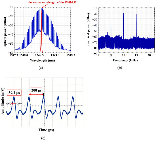
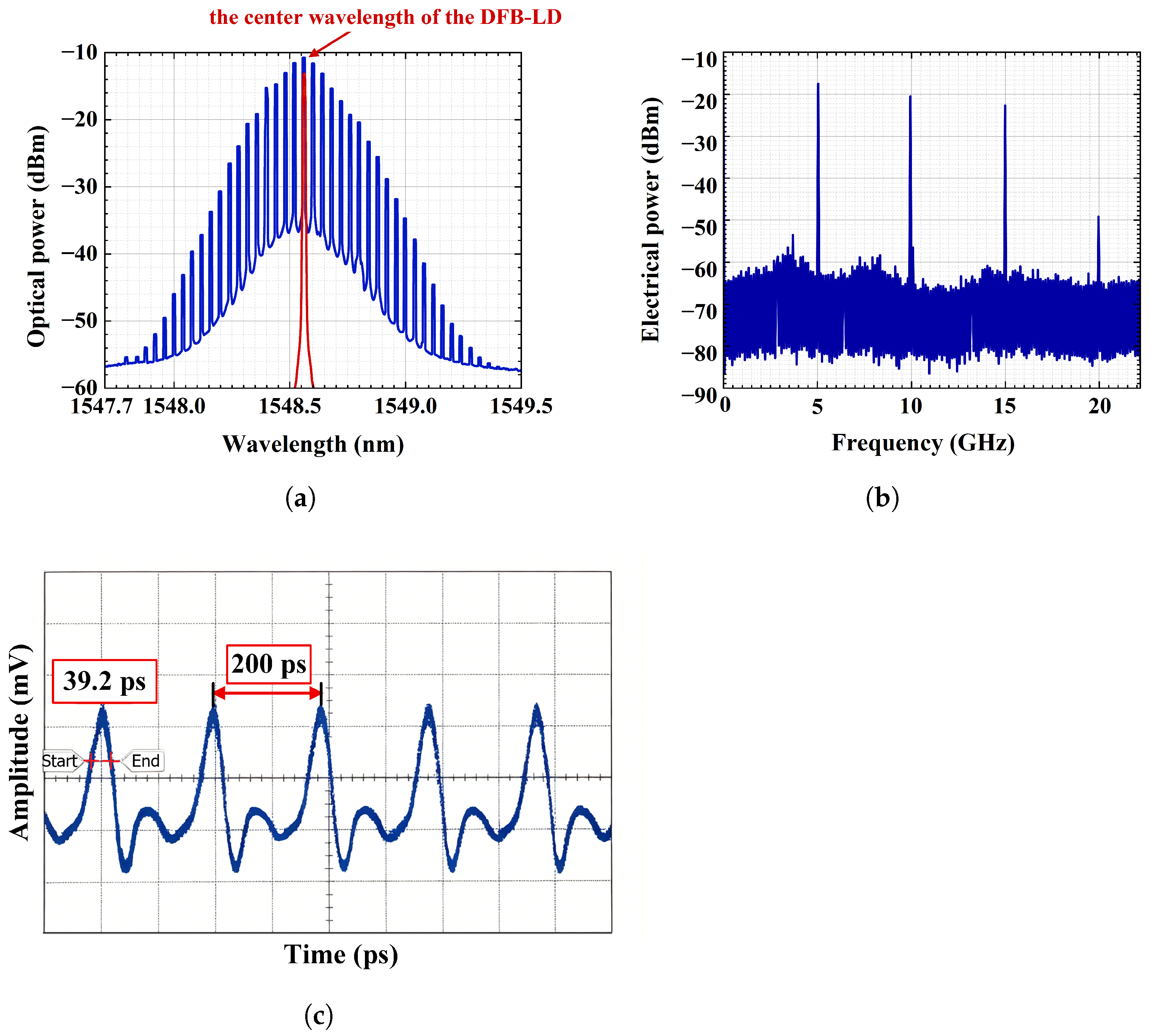
When the frequency stabilization module is activated, the system operates as an injection-locked AMLFL with frequency stabilization. After adjusting the ODL to maintain the AMLFL in a mode-locked state, the resulting optical spectrum, electrical spectrum, and time-domain waveform of the system output field are shown in Figure 8. It can be observed that the center wavelength of the spectrum remains near 1548.55 nm. The oscilloscope-measured temporal pulse width is 39.2 ps, and the repetition rate is 5 GHz. Similarly, when frequency-stabilized injection is applied, the injected DFB-LD light mainly suppresses wavelength drift and power fluctuation. Since the gain bandwidth, RF modulation condition, and intracavity dispersion remain nearly unchanged, the oscilloscope-measured temporal pulse width remains close to those obtained under the other two operating conditions.
Figure 8.
Experimental results of injection into the AMLFL with frequency stabilization. (a) The measured optical spectrum. (b) The measured RF spectrum. (c) The corresponding time-domain waveform.
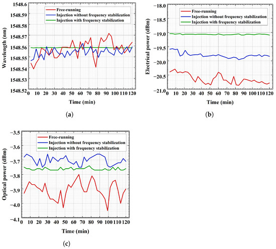
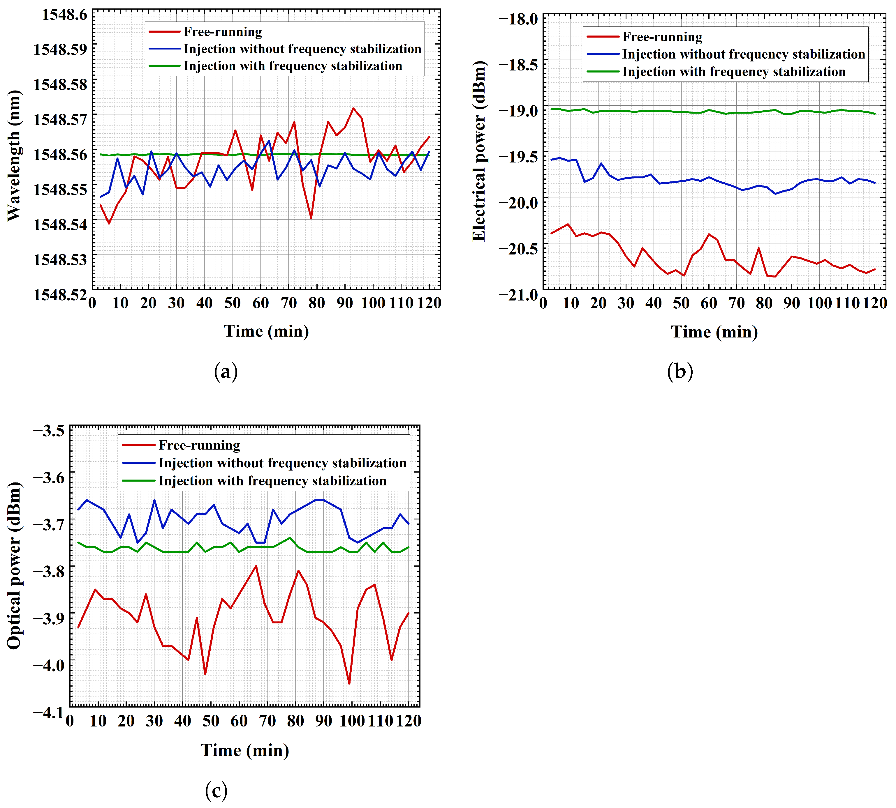
To compare the stability of the AMLFL output under three conditions, namely free-running, injection without frequency stabilization, and injection with frequency stabilization, experimental data are recorded over a 2 h observation period. The spectral line located near the center wavelength of the AMLFL output spectrum, approximately 1548.55 nm, is chosen as the selected wavelength. During the stability test, the output spectrum of the AMLFL is recorded every three minutes using the OSA, which has a wavelength resolution of 10.00 pm. The center wavelength of the selected spectral line is extracted from each recorded spectrum, and the collected values are used to evaluate the wavelength drift given in Figure 9a. The experimental curve of the free-running AMLFL is represented by the red line. Similarly, the corresponding curve under injection without frequency stabilization is depicted by the blue line. The case of injection into the AMLFL with frequency stabilization is presented by the green line. The horizontal axis is the observation time, fixed at two hours. The vertical axis represents the wavelength data of the output light. Comparing the three curves clearly shows that free-running AMLFL exhibits the largest wavelength drift range. In contrast, injection into the AMLFL with frequency stabilization significantly reduces the wavelength drift range, demonstrating the best long-term wavelength stability. The comparison of the power fluctuation of the 5 GHz spectral component is shown in Figure 9b, while the comparison of average power drift of the output optical pulse is presented in Figure 9c. The data shown in Figure 9b,c are obtained over a 2 h period under each operating condition, with observations recorded every three minutes. It can be clearly seen that, among the three conditions mentioned above, injection into the AMLFL with frequency stabilization exhibits the smallest power fluctuation of the 5 GHz spectral component and the smallest average power drift of the output optical pulse, demonstrating the best overall performance. The similar time-domain waveforms in Figure 6, Figure 7 and Figure 8 mainly verify stable mode-locked operation under the three conditions, while the stability improvement is evaluated from the long-term wavelength and power fluctuations.
Figure 9.
Experimental results for free-running AMLFL, injection into the AMLFL with and without frequency stabilization. (a) Wavelength drift of a selected wavelength. (b) The power fluctuation of the 5 GHz spectral component. (c) Average power of the output optical pulse.
To comprehensively evaluate the three conditions described above, a comparative analysis is performed. The data shown in Figure 9 are further quantitatively organized into tabular form. The results are summarized in Table 1, which lists the maximum drift ranges (MDRs) of a selected wavelength, the electrical power of the 5 GHz spectral component, and the average optical power within the observation period. As shown in Table 1, for injection into the AMLFL with frequency stabilization, the wavelength drift is within the 10 pm resolution limit of the OSA. Meanwhile, the maximum electrical power fluctuation of the 5 GHz spectral component is 0.05 dB, and the maximum fluctuation of the average optical pulse power is 0.03 dB.
Table 1.
Comparison of performance of free-running AMLFL and injection into the AMLFL with and without frequency stabilization.
To further evaluate the stability of the system output, the standard deviations (SDs) of the electrical power fluctuation of the 5 GHz spectral component and the average optical power fluctuation are calculated and summarized in Table 2. In the case of injection into the AMLFL with frequency stabilization, both SD values are lower than those under the other two conditions. These results demonstrate that the proposed frequency-stabilized injection scheme effectively improves the power stability of the AMLFL output.
Table 2.
Comparison of drift SD of free-running AMLFL, injection into the AMLFL with and without frequency stabilization.
5. Discussion
To provide contextual information on the operating conditions of related AMLFL systems, several previously reported systems and the proposed system are summarized in Table 3. It should be noted that Table 3 is not intended to directly compare different instability metrics, but rather to provide background information on the observation time, repetition frequency, and center wavelength of representative systems.
Table 3.
Comparison of previously reported systems and the proposed system.
From all the experimental results presented above, the significance and practicality of this system are well demonstrated. A frequency-stabilized DFB-LD based on the F-P etalon is passively injected into the cavity of the AMLFL, which significantly improves the output stability of the AMLFL in terms of the wavelength drift of a selected wavelength, power fluctuation of the 5 GHz spectral component, and average power of the output optical pulse. The experimental results are in good agreement with the theoretical analysis, thereby confirming its reliability. In addition, the optical injection scheme does not alter the intrinsic cavity structure of the AMLFL, providing a cost-effective and flexible solution for high-stability AMLFL systems.
6. Conclusions
We have proposed and experimentally demonstrated a high-stability AMLFL based on DFB-LD injection locking with F-P frequency stabilization. In this system, wavelength modulation is employed, and the frequency-stabilized feedback signal is obtained by exploiting the linear response of the first-order derivative of a transmission peak of the F-P etalon. This frequency-stabilized optical source is then passively injected into the ring cavity of the AMLFL. The experimental results show that, under the free-running AMLFL condition, the MDR of a selected wavelength is approximately 30 pm. Without frequency stabilization, the MDR of the same wavelength drift is reduced to approximately 20 pm. With frequency stabilization, the wavelength drift is further reduced to within the 10 pm resolution of the OSA. Furthermore, the output stability of the AMLFL is significantly improved in the electrical spectrum and average power of the output optical pulse. Specifically, the SD of the power fluctuation of the 5 GHz spectral component is reduced to 0.01 dB, and the SD of the average output optical pulse power is also reduced to 0.01 dB after frequency stabilization. The scientific novelty of this work lies in using an externally frequency-stabilized DFB-LD as the injection source to improve the long-term wavelength and power stability of an AMLFL without modifying its original main ring cavity. The system features a low cost and a simple structure and is expected to find applications in high-speed optical communications and microwave photonics in the future.
Author Contributions
Conceptualization, J.W., M.L. and H.L.; methodology, J.W., M.L. and H.L.; software, X.L. and X.S.; validation, J.W., C.M. and J.Y.; writing—original draft preparation, M.L. and H.L.; writing—review and editing, J.W., and J.Y.; supervision, J.W., J.Y. and C.M. All authors have read and agreed to the published version of the manuscript.
Funding
This research was funded by National Natural Science Foundation of China (62505217).
Institutional Review Board Statement
Not applicable.
Informed Consent Statement
Not applicable.
Data Availability Statement
The data presented in this study are available on request from the corresponding author.
Conflicts of Interest
The authors declare no conflicts of interest.
References
- Wang, W.; Wang, C.; Zhao, F.; Zhu, L.; Liu, S.; Ma, X. High-power 976 nm first-order DFB laser diode with 64% efficiency. Opt. Laser Technol. 2026, 196, 114623. [Google Scholar] [CrossRef] [Scilit]
- Chen, L.; Huang, J.; Sun, W.; Li, Z.; Jiang, C.; Wang, Y.; Jiang, Y.; Zhang, L.; Jiang, X.; Pang, M. High power mid-infrared side-pump combiner with good thermal stability based on the point-by-point fusion splicing technique. Opt. Express 2024, 32, 39710–39717. [Google Scholar] [CrossRef] [Scilit] [PubMed]
- Kang, P.; Liu, Y.; Li, E.; Wang, J.; Yao, W.; Peng, Y.; Leng, Y. High-power Ho:YAG MOPA system pumped by a Tm-fiber laser with 269 W average output power at 10 kHz. Opt. Express 2025, 33, 39597–39604. [Google Scholar] [CrossRef] [Scilit] [PubMed]
- Massabeau, S.; Reep, T.; Wu, C.H.; Brems, S.; Yudistira, D.; Van Campenhout, J.; Kuyken, B.; Larat, C.; Van Thourhout, D.; Baili, G. Compact and electrically driven active mode-locked laser at 10 GHz repetition rate based on a graphene electro-absorption modulator. Opt. Lett. 2026, 51, 1315–1318. [Google Scholar] [CrossRef] [Scilit] [PubMed]
- Li, M.; Qin, L.; Li, X.; Zhang, J.; Zhang, Y.; Li, J.; Li, S.; Li, G. Study on characteristics of noise-like pulses and dissipative soliton resonance pulses in nonlinear multimode interference mode-locked fiber lasers. Opt. Laser Technol. 2025, 187, 112799. [Google Scholar] [CrossRef] [Scilit]
- Yao, S.; Xu, Y.; Zhang, M.; Yan, X.; Bao, H. Precise selection and amplification of a single comb line from femtosecond mode-locked lasers. Opt. Lett. 2024, 49, 710–713. [Google Scholar] [CrossRef] [Scilit] [PubMed]
- Ma, X.; Lv, J.; Luo, J.; Liu, X.; Yao, P.; Xu, L. Pulse convergence analysis and pulse information calculation of NOLM fiber mode-locked lasers based on machine learning method. Opt. Laser Technol. 2023, 163, 109390. [Google Scholar] [CrossRef] [Scilit]
- Zhao, X.; Wei, Y.; Wang, L.; Wu, J.; Zhao, Y.; Shen, J.; Xu, Y.; Zhang, W.; Bai, C.; Lu, C.; et al. Investigation on multiple soliton operations in erbium-doped fiber lasers based on Bi2O2Te saturable absorbers. Opt. Commun. 2025, 588, 132000. [Google Scholar] [CrossRef] [Scilit]
- Xiang, Y.; Bai, S.; Zhang, Z. Cylindrical vector beam generation from a passively mode-locked Raman fiber laser. Opt. Laser Technol. 2023, 160, 109079. [Google Scholar] [CrossRef] [Scilit]
- Reep, T.; Wu, C.; Brems, S.; Yudistira, D.; Van Campenhout, J.; Pantouvaki, M.; Van Thourhout, D.; Kuyken, B. Active and passive mode-locking of a laser using a graphene modulator on an SOI chip. In Proceedings of the 2023 IEEE Photonics Conference, Orlando, FL, USA, 12–16 November 2023; IEEE: Piscataway, NJ, USA, 2023; pp. 1–2. [Google Scholar]
- Wang, H.Y.; Sheng, X.Z.; Li, Z.Y.; Zhan, X.K.; Wang, S.C.; Wang, B.C.; Bao, Y.S. High-order actively mode-locked picosecond fiber laser and Poissonian single-photon source. Opt. Commun. 2019, 453, 124394. [Google Scholar] [CrossRef] [Scilit]
- Pan, R.; Fu, Y.; Xiao, P.; Zhang, C.; Hao, S.; Liu, Z.; Ma, W. Low-noise tunable high-repetition-frequency fiber laser based on an active–passive hybrid mode-locking mechanism. Appl. Opt. 2024, 63, 9283–9288. [Google Scholar] [CrossRef] [Scilit]
- Hua, K.; Wang, D.N. Coupling scheme for graphene saturable absorber in a linear cavity mode-locked fiber laser. Opt. Lett. 2021, 46, 4362–4365. [Google Scholar] [CrossRef] [Scilit] [PubMed]
- Ahmad, H.; Tahrin, R.A.A.; Azman, N.; Kassim, S.; Ismail, M.A.; Maah, M.J. 1.5-micron fiber laser passively mode-locked by gold nanoparticles saturable absorber. Opt. Commun. 2017, 403, 115–120. [Google Scholar] [CrossRef] [Scilit]
- Kim, J.; Song, Y. Ultralow-noise mode-locked fiber lasers and frequency combs: Principles, status, and applications. Adv. Opt. Photon. 2016, 8, 465–540. [Google Scholar] [CrossRef] [Scilit]
- Zhang, Y.; Li, J.; Meng, C.; Li, S.; Zeng, Z.; Zhang, L.; Zhang, Z.; Zhang, S.; Liu, Y. Actively mode-locked modulator-free optoelectronic oscillator for multi-functional microwave pulse generation. J. Light. Technol. 2024, 42, 6760–6766. [Google Scholar] [CrossRef] [Scilit]
- Bogusławski, J.; Wang, Y.; Xue, H.; Yang, X.; Mao, D.; Gan, X.; Ren, Z.; Zhao, J.; Dai, Q.; Soboń, G.; et al. Graphene actively mode-locked lasers. Adv. Funct. Mater. 2018, 28, 1801539. [Google Scholar] [CrossRef] [Scilit]
- Yao, G.; Zhao, Z.; Liu, Z.; Gao, X.; Cong, Z. High repetition rate actively mode-locked Er:fiber laser with tunable pulse duration. Chin. Opt. Lett. 2022, 20, 071402. [Google Scholar] [CrossRef] [Scilit]
- Zhang, X.; Guo, Y.; Xue, X.; Li, T.; Cui, Z.; Li, H.; Chen, X.; Zheng, Y.; Chen, J.; Wu, K. Broadband III-V/Lithium Niobate Actively Mode-Locked Lasers. Laser Photonics Rev. 2026, 20, e01886. [Google Scholar] [CrossRef] [Scilit]
- Gui, L.; Zhang, S.; Chu, Z.; Zhan, Q.; Wang, A. Active Mode-Locking All-Fiber Laser with Switchable Multi-Transverse-Mode Operation. J. Light. Technol. 2026, 44, 4790–4796. [Google Scholar] [CrossRef] [Scilit]
- Yan, P.; Hu, H.; Li, Z.; Xu, W. Optical high repetition rate stabilization based an all-polarization-maintaining figure-of-nine Er-fiber laser. Opt. Commun. 2022, 513, 128081. [Google Scholar] [CrossRef] [Scilit]
- Kwon, D.; Kim, D. Ultralow Intensity Noise Pulse Train from an All-fiber Nonlinear Amplifying Loop Mirror-based Femtosecond Laser. Curr. Opt. Photonics 2023, 7, 708–713. [Google Scholar]
- Pan, R.; Jia, J.; Hu, X.; Zhang, T.; Zhang, W.; Yang, Y.; Feng, Y.; Wang, Y.; Si, J. Compact all-polarization-maintaining dual femtosecond fiber laser system with large repetition rate tuning ranges based on self-made fiber actuators. Opt. Express 2025, 33, 18866–18890. [Google Scholar] [CrossRef] [Scilit] [PubMed]
- Billault, V.; Baili, G.; de Chatellus, H.G.; Morvan, L.; Dolfi, D.; Crozatier, V. Experimental Investigation on Dynamic Properties and Noise Reduction in Actively Mode-Locked Lasers by External CW Optical Injection. J. Light. Technol. 2021, 39, 2924–2930. [Google Scholar] [CrossRef] [Scilit]
- Krzempek, K. High-precision passive stabilization of a dissipative soliton resonance laser repetition rate based on optical pulse injection. Opt. Lett. 2024, 49, 4118–4121. [Google Scholar] [CrossRef] [Scilit] [PubMed]
- Hao, J.; Tang, L.; Ye, H.; Hao, Z.; Han, J.; Zhai, Y.; Zhang, K.; Wei, R.; Xiao, D. Effect of near-field distribution on transmission characteristics of fiber-fed Fabry-Perot etalons. Astron. J. 2021, 161, 258. [Google Scholar] [CrossRef] [Scilit]

Disclaimer/Publisher’s Note: The statements, opinions and data contained in all publications are solely those of the individual author(s) and contributor(s) and not of MDPI and/or the editor(s). MDPI and/or the editor(s) disclaim responsibility for any injury to people or property resulting from any ideas, methods, instructions or products referred to in the content. |
© 2026 by the authors. Licensee MDPI, Basel, Switzerland. This article is an open access article distributed under the terms and conditions of the Creative Commons Attribution (CC BY) license.