Skip to Content
  • Article
  • Open Access

15 August 2026

Dual-Rotary Trepanning of High-Quality Film Cooling Holes in DD6 Superalloy Using a Nanosecond Fiber Laser

,
,
,
,
,
,
,
,
and
1
Basic Science Center Project of Light Manufacturing Science and Engineering, Institute of Laser Manufacturing, Henan Academy of Sciences, Zhengzhou 450046, China
2
College of Information and Engineering and Artificial Intelligence, Henan University of Science and Technology, Luoyang 471023, China
3
State Key Laboratory of Precision Spectroscopy, School of Physics and Electronic Science, East China Normal University, Shanghai 200241, China
*
Authors to whom correspondence should be addressed.

Abstract

High-quality and high-efficiency machining of film cooling holes (FCHs) is critical for enhancing the performance of gas turbines and aero-engines. Nanosecond fiber lasers offer advantages such as high stability, good beam quality, and ease of integration. However, when machining FCHs, issues including low drilling efficiency and significant thermal effects severely limit their industrial applications. In this study, a dual-rotary trepanning system was developed based on a nanosecond fiber laser, a galvanometer, and a five-axis cradle machine. High-quality FCHs with a diameter of 0.6 mm were efficiently machined in a 3-mm-thick DD6 superalloy plate within only 6.5 s. Compared with the method using machine tool rotation alone, the average recast layer thickness on the inner wall was reduced by 62.1% to 6.7 μm, and the average surface roughness was reduced by 61.1% to 0.35 μm. These improvements are primarily attributed to the galvanometer speed being two orders of magnitude higher than that of the machine tool, which significantly reduces the laser pulse overlap rate and the thermal accumulation effect. Moreover, the kerf widened by the galvanometer rotation allows the ablation products to expand more fully and be expelled efficiently, thereby reducing impact, scratching, and debris adhesion on the inner wall and improving the drilling efficiency. Furthermore, 10 × 10 FCH arrays were machined on both vertical and inclined plates, demonstrating high consistency and stability, indicating the potential for industrial applications in the field of FCH machining.

1. Introduction

Nickel-based single crystal superalloy DD6 exhibits excellent strength, microstructural stability, and creep resistance under high-temperature environments [1,2,3,4], making it widely used in turbine blades and flame tubes (collectively referred to as hot components) of aero-engines and gas turbines [5,6,7]. However, the operating temperature of the hot gases has exceeded the long-term endurance limit of the DD6 superalloy [8,9]. Therefore, film cooling hole (FCH) technology is extensively applied to enhance the high-temperature resistance. This technology involves designing the positions and orientation angles of the FCHs based on the geometry of the flame tube and blades. By machining hundreds to tens of thousands of FCHs, cooling air is ejected at high velocity through these holes, forming a cooling film that covers the surface of the hot components, thereby forming a barrier against the hot gases for thermal protection [10,11].
The processing quality of FCHs, including geometric accuracy and inner wall quality, significantly affects their cooling efficiency and fatigue resistance [12,13,14,15]. In recent decades, achieving high-quality and high-efficiency processing of FCHs has long remained a critical factor in enhancing the performance and service life of aero engines and gas turbines [16,17].
At present, the main FCH-processing methods include electrical discharge drilling (EDD) [18,19], electrochemical drilling (ECD) [20], and laser drilling [21,22,23]. EDD can efficiently process FCHs with good circularity; however, the process is accompanied by the formation of a thick recast layer and numerous micro-cracks, along with significant electrode wear. ECD can produce high-quality FCHs, but its efficiency is extremely low. Laser machining has emerged as a preferred method due to its advantages such as the absence of tool wear, high flexibility, and high processing efficiency [24,25,26]. Laser pulse width is a critical parameter that determines the laser-material interaction. Based on pulse width, laser processing can be categorized into quasi-continuous wave (QCW) laser drilling [27,28,29], nanosecond laser drilling [30,31,32] and ultrafast drilling [33,34,35].
A QCW laser removes material through melting and ablation induced by heating, with the material being ejected under the combined action of recoil pressure and high-pressure assist gas. Marimuthu et al. used a QCW laser to machine micro-holes with a diameter of 0.75 mm in a 5-mm-thick nickel-based alloy plate [27]. This method offers high machining efficiency; however, the inner wall quality is poor, characterized by a thick recast layer of up to 30 μm and a high surface roughness of 10 μm. These issues reduce the mechanical strength of the hot components, disrupt the uniformity of the cooling film distribution, and reduce the cooling efficiency [36,37].
Due to the ultrashort pulse durations, femtosecond and picosecond lasers induce minimal thermal effects during the processing of FCHs [38,39,40,41]. To enhance the quality and efficiency of FCH processing, researchers have developed various methods, including galvanometer-based spiral drilling, optical wedge drilling, and multi-step processing assisted by high-pressure air [42,43,44,45,46]. However, limited by the low pulse energy and low average power of ultrafast lasers, the processing efficiency remains low. For instance, processing a single micro-hole with a diameter of 500 μm in a 1.5-mm-thick DD6 substrate takes more than 25 s [34]; when machining deep holes with an aspect ratio exceeding 5, the processing time increases significantly. Consequently, ultrafast laser processing still falls short of meeting the demands of high-efficiency, large-scale industrial applications at present.
Considering the advantages and disadvantages of ultrafast lasers and QCW lasers for machining FCHs, and in view of the practical demands of industrial manufacturing, this study adopts a nanosecond fiber laser for FCH drilling. (a) Potential for balancing efficiency and quality: Nanosecond fiber lasers feature a short pulse duration, high average power, and excellent stability, offering the potential to achieve both high quality and high efficiency when processing microholes in thin plates [31,47,48,49]. (b) Superior system integration, robust stability, and environmental compatibility: The nanosecond fiber laser, which enables beam delivery through a flexible optical fiber, can be readily integrated with existing five-axis CNC machine tools, offering strong engineering practicality. Furthermore, its excellent stability and environmental adaptability ensure consistent quality in high-volume machining of FCHs.
However, as the aspect ratio of FCHs increases, the recast layer thickness and inner-wall surface roughness of the FCHs increase rapidly [45]. The significant thermal effects associated with nanosecond laser drilling of deep microholes restrict its industrial applications. In recent years, few relevant studies have been reported.
Many references primarily focus on water-jet guided nanosecond laser processing, which aims to further reduce thermal effects, decrease recast layer thickness and surface roughness, and significantly increase the aspect ratio of FCHs [50,51]. However, this method still faces several limiting factors in large-scale industrial applications. First, plasma breakdown of the water jet restricts the usable laser power, resulting in low processing efficiency. Second, high-pulse-energy nanosecond lasers typically employ free-space beam delivery, which poses challenges for integration with multi-axis machine tools. Furthermore, factors such as the high-pressure water jet also affect the stability of the processing system.
To address the urgent industrial demand for high-quality, high-efficiency, and high-stability FCH processing, this work establishes a laser machining center using the dual-rotary trepanning method. In this setup, a nanosecond fiber laser is coupled with a two-dimensional galvanometer to form a processing head, which is fixed to the Z-axis of a cradle-type five-axis machine tool. During processing, the galvanometer oscillates to achieve high-speed rotation of the laser beam along a small-diameter circular path, while the machine tool simultaneously drives the galvanometer processing head to perform large-diameter annular trepanning. Compared with the machine tool single-rotary trepanning method, the high-speed rotation of the galvanometer reduces the laser pulse overlap rate, effectively minimizing heat accumulation and thermal damage. Concurrently, the galvanometer rotation increases the kerf width, allowing ablation products to expand more fully, thereby reducing impact and scratching, and minimizing debris adhesion on the inner wall. The dual-rotary trepanning method enables the efficient (6.5 s per hole) and highly stable processing of high-quality FCHs: the recast layer thickness and inner-wall surface roughness are significantly reduced, the exit circularity is greatly improved, and two 10 × 10 arrays of FCHs were fabricated on plates with inclination angles 90° (vertical) and 45° exhibit excellent uniformity.

2. Materials and Methods

2.1. Materials

The microstructure of the DD6 superalloy primarily consists of γ phase and γ’ phase. This structural configuration offers significant advantages in enhancing its high-temperature mechanical properties [52,53]. The alloy contains various refractory alloying elements (e.g., Ni, W, Ta, Co, Cr, Mo), ultimately forming a high-purity, dense austenitic structure. The fundamental chemical composition is presented in Table 1. The DD6 superalloy utilized in this study was provided by AECC Beijing Institute of Aeronautical Materials, with sample dimensions of 50 mm × 25 mm × 3 mm.
Table 1. Chemical composition (wt.%) of superalloy DD6.

2.2. Experimental System

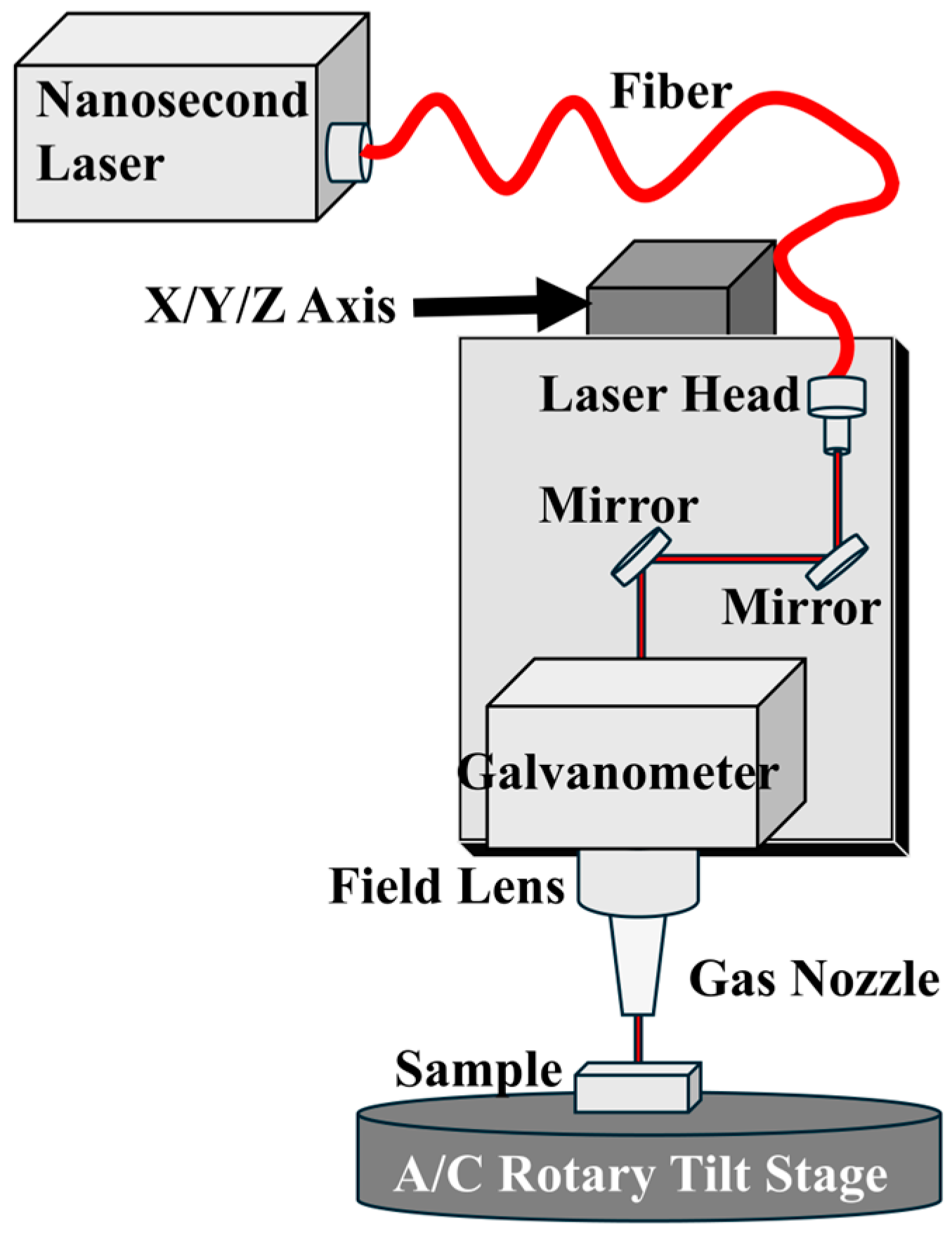
The schematic diagram of the nanosecond fiber laser machining center is shown in Figure 1. It mainly consists of a nanosecond fiber laser, a cradle-type five-axis CNC machine tool, a galvanometer scanning and focusing system, and a high-pressure assist gas nozzle. The nanosecond laser (YLPN300, IPG, Marlborough, MA, USA) delivers laser pulses with a central wavelength of 1064 nm, a single pulse energy of 1.33 mJ, a repetition frequency of 135 kHz, and an average power of 180 W. The galvanometer system is fixed to the Z-axis of the five-axis machine tool via an optical mounting plate and can move along the X, Y, and Z directions. The fiber laser beam is directed into the galvanometer (excelliSCAN 20, SCANLAB, Puchheim, Germany) by two reflecting mirrors. This galvanometer features a scanning accuracy of 0.4 μrad, a maximum scanning speed of 70 rad/s, and a long-term drift of less than 25 μrad.
Figure 1. Schematic diagram of the nanosecond fiber laser machining center.
A field lens with a focal length of 100 mm is installed below the galvanometer, focusing the laser beam to a spot diameter of 50 μm. The assist air, with a maximum pressure of 0.65 MPa, is delivered through a nozzle with a diameter of 3.5 mm to cool the workpiece, with a standoff distance of 10 mm between the nozzle and the workpiece surface [54,55,56]. The workpiece is secured by a vise mounted on an A/C-axis rotary tilt stage. The ambient room temperature was maintained at 24.8 ± 0.3 °C, and the relative humidity was kept at 44.6 ± 2.1%.

2.3. Processing Methods

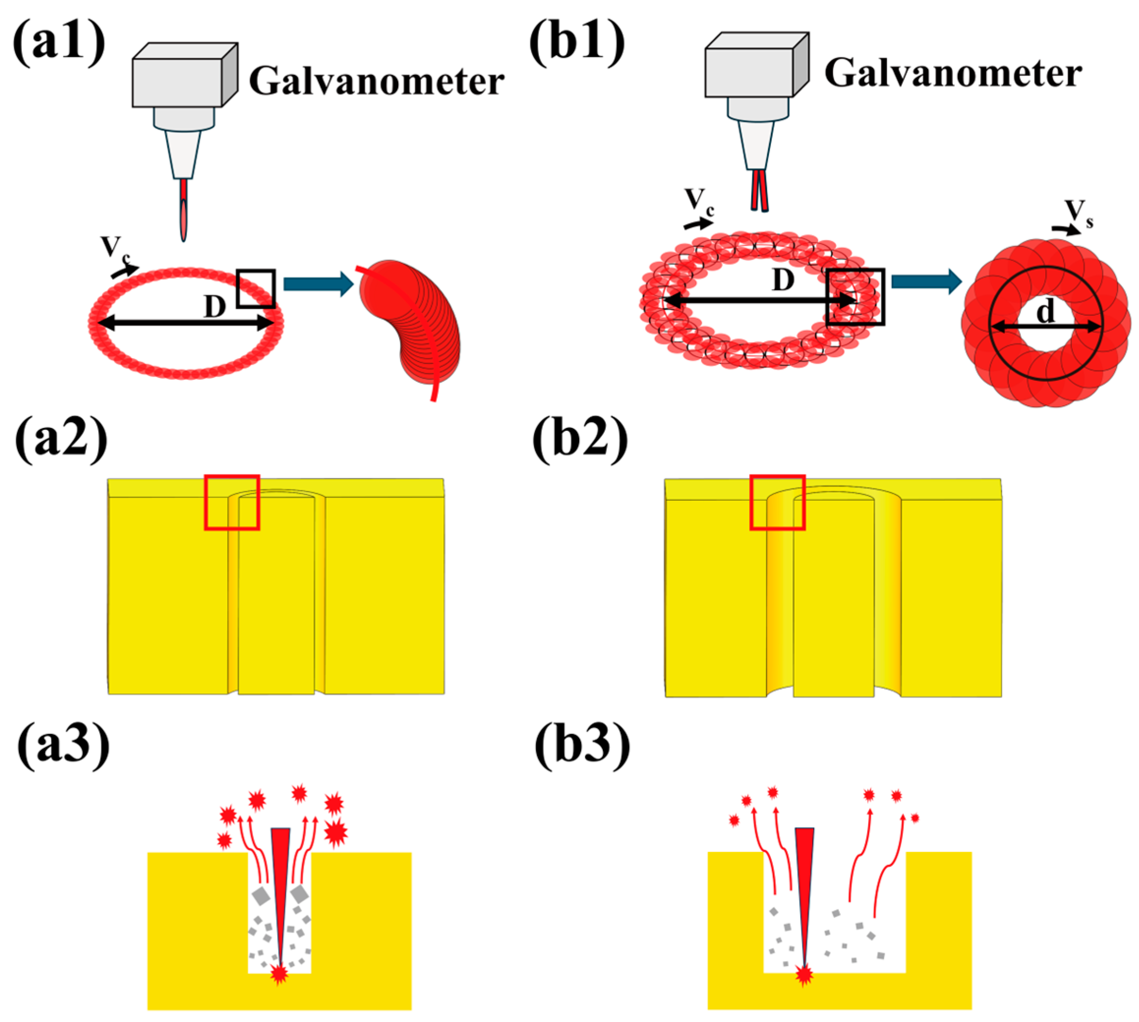
In industrial applications, FCHs in gas turbine blades and aero-engine combustor liners are typically fabricated by adjusting the laser incidence angle using a dual swivel head or a rotary tilt stage, with the machine tool’s Z-axis driving the laser processing head to perform annular trepanning, as shown in Figure 2(a1) [57]. This method produces round holes with high circularity and low taper [27]. However, due to the continuous high-acceleration motion of the processing head, its rotational speed Vc is low, typically only a few mm/s, resulting in a high laser pulse overlap rate. Consequently, significant heat accumulation occurs during processing, leading to an increased thickness of the recast layer on the inner wall of FCHs, along with pronounced defects such as microcracks and pits. Furthermore, the kerf width is extremely narrow, typically several tens of micrometers, while the depth of FCHs is generally on the order of several millimeters, yielding an aspect ratio as high as 40:1 to 100:1. This restricts the efficient evacuation of ablation products from such narrow kerfs, resulting in severe adhesion of debris to the hole wall and high surface roughness.
Figure 2. Schematic diagrams of two FCH-processing methods. (a1) Machine tool single-rotary trepanning. (b1) Galvanometer-machine tool dual-rotary trepanning. (a2,b2) Kerf morphology. (a3,b3) Expansion and evacuation of ablation products in the kerf.
This study proposes a dual-rotary trepanning method for the fabrication of FCHs by combining the rotations of a galvanometer and a machine tool, as illustrated in Figure 2(b1). In this method, the galvanometer performs a high-speed circular scanning with a small diameter d at a speed Vs of several hundred mm/s, while the Z-axis of the machine tool drives the laser processing head to execute a low-speed circular motion with a large diameter D. This technique can simultaneously improve both the quality and efficiency of FCH processing, which can be primarily attributed to the following two aspects.
(1) Significant reduction in pulse overlap and mitigation of heat accumulation.
The high-speed rotation of the galvanometer significantly reduces the cumulative pulse count (CPC), thereby effectively suppressing heat accumulation effects during processing. The CPC is calculated by the formula f D f / V , where f is the laser repetition frequency, D f is the focal spot diameter, and V is the motion speed of the galvanometer or the machine tool.
(2) Increasing the kerf width, enhancing ejecta efficiency, and reducing the plasma shielding effect.
This method increases the kerf width, as shown in Figure 2(b2,b3), which facilitates more sufficient expansion of ablation products, thereby enhancing the efficiency of debris evacuation from the hole [58], mitigating the plasma shielding effect, and reducing debris adhesion to the hole wall.

2.4. Post-Processing and Measurements

After laser processing, the DD6 specimens were first ground with sandpaper to remove spatter around the hole entrances and exits. Subsequently, the specimens were longitudinally sectioned along the central axis of the FCHs, and the cross-sections were precision-polished. Finally, the specimens were ultrasonically cleaned in anhydrous ethanol to remove surface residues. A scanning electron microscope (SEM, JSM-IT800, JEOL, Tokyo, Japan) was employed to observe the entrance and exit morphologies as well as the microstructure of the inner walls. Furthermore, energy-dispersive spectroscopy (EDS) was conducted to determine the elemental composition. A metallurgical micro-scope (VHX-7000N, KEYENCE, Osaka, Japan) was used to analyze the characteristics of the recast layer on the inner walls, and a confocal optical microscope (COM, OLS5100, OLYMPUS, Tokyo, Japan) was utilized to acquire the three-dimensional morphology and measure the surface roughness of the inner walls.
The geometric parameters of FCHs include the entrance diameter, exit diameter, taper, and exit roundness [59]. The exit roundness is calculated as D m i n / D m a x , where D m a x is the diameter of the circumscribed circle, and D m i n is the diameter of the inscribed circle. The closer the roundness value is to 1, the better the roundness of the FCHs.
Inner wall defects were marked and measured using ImageJ 1.54p software. The number, width, and length of microcracks, as well as the total area of pits on the inner wall, were statistically analyzed.

3. Results

3.1. Processing FCHs Using Single-Rotary Trepanning with Machine Tool

Machining of FCHs via circular trepanning using a machine tool is the primary method currently employed in industrial applications [57]. In this study, the focus offset was set to −2.0 mm, meaning that the laser focus was positioned 2.0 mm below the top surface of the specimen. The FCHs were fabricated by driving the machine tool to move along a circular trajectory with a diameter of 0.56 mm. The effects of the machine tool speed and processing time on the entrance/exit morphologies and inner wall quality were investigated, respectively.
The speed of the machine tool was set to 5.0 mm/s, and the laser processing time was varied from 1 to 13 s. The results showed that when the processing time exceeded 3.4 s, complete penetration of FCHs could be achieved. When the processing time exceeded 8.4 s, the exit diameter and circularity of the FCHs reached a relatively high level and tended to stabilize. Accordingly, the optimized processing time was determined to be 8.4 s.
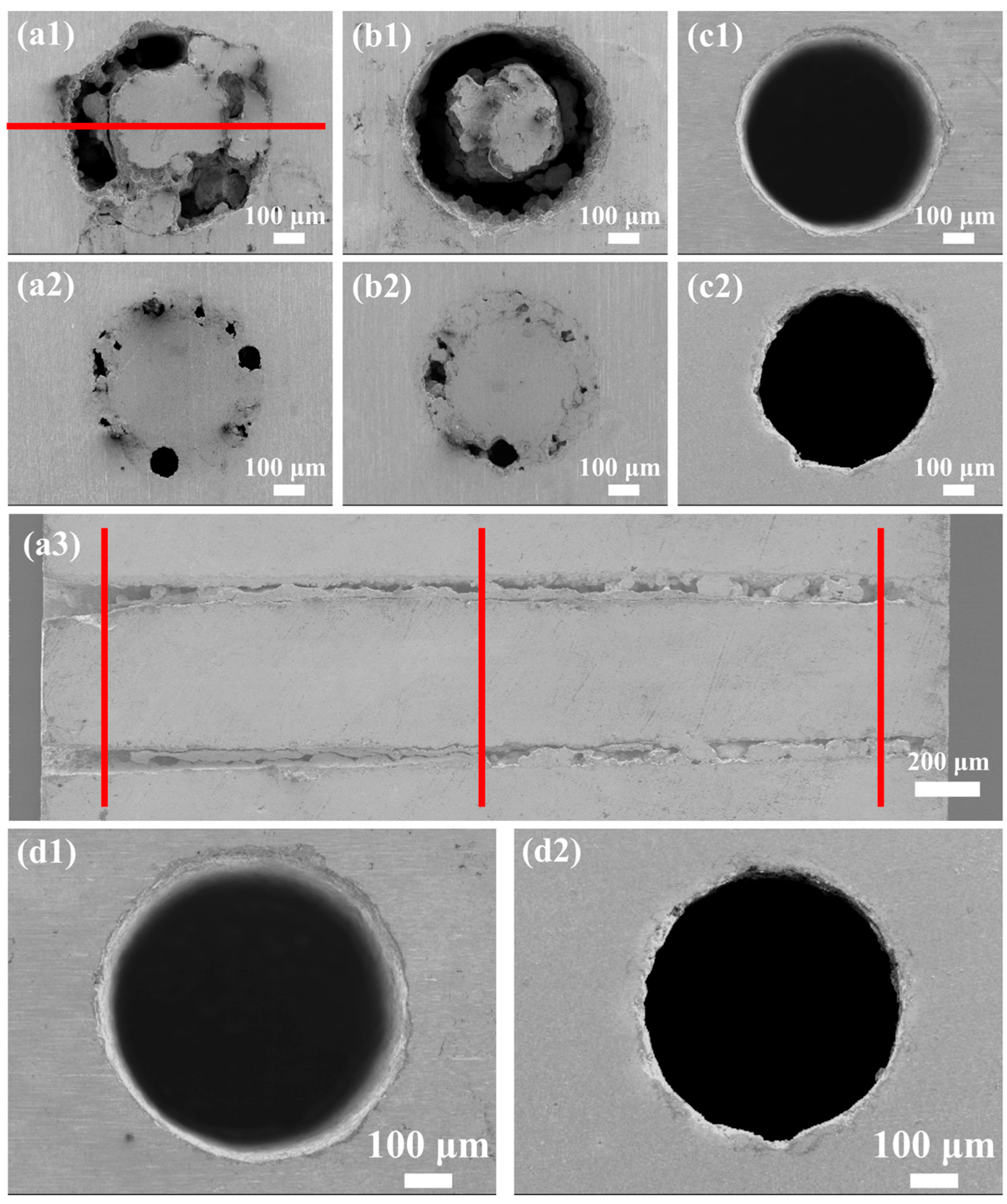
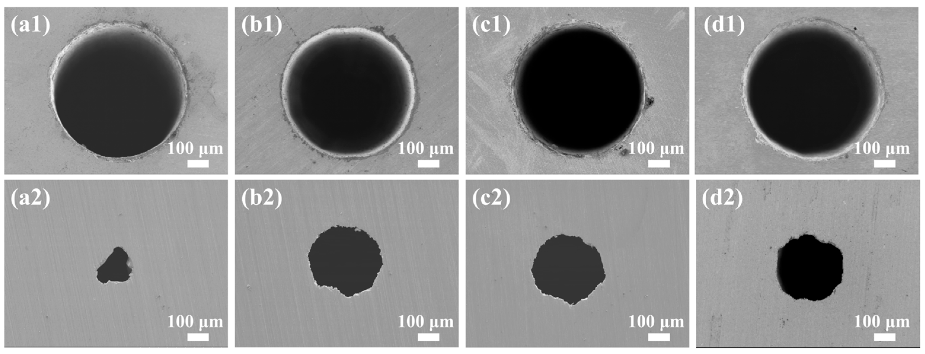
The processing time was set to 8.4 s, and the motion speed of the machine tool was varied from 0.83 mm/s to 13.3 mm/s. The entrance and exit morphologies of the fabricated FCHs are shown in Figure 3. At motion speeds of 0.83 mm/s and 1.67 mm/s, the lower speeds resulted in incomplete penetration of the holes and irregular entrance morphologies. When the speed exceeded 2.0 mm/s, complete penetration was achieved, with regular entrance morphologies and an approximately constant entrance diameter of 643.5 ± 1.9 μm. At a speed of 2.5 mm/s, the exit diameter was 565 μm, with a roundness of 0.873. When the speed exceeded 8.3 mm/s, both the exit diameter and roundness gradually decreased.
Figure 3. SEM images of the entrance (a1d1) and exit (a2d2) morphologies for different motion speeds using single-rotary trepanning. (ad) Correspond to motion speeds of 0.83 mm/s, 1.67 mm/s, 2.5 mm/s, and 5.0 mm/s, respectively. (a3) The axial cross-sectional image along the red line indicated in (a1).
Figure 3(a3) shows a cross-sectional image of the microhole fabricated at a speed of 0.83 mm/s. The cutting kerf formed by rotary trepanning was very narrow, with slit widths of approximately 93 μm, 65 μm, and 56 μm at the entrance, middle, and exit, respectively, yielding an average width of only 71 μm. At this low rotational speed, the cumulative number of pulses was extremely high, resulting in significant thermal effects [60]. Excessive pulse accumulation causes continuous plasma ejection within the narrow slit, preventing the timely expulsion of ablated debris. This induced a notable plasma shielding effect, which absorbed a portion of the incident laser energy and reduced the drilling efficiency [61]. Furthermore, the high-density ablated material could not expand sufficiently, and its violent ejection caused bursts and erosion at the hole exit.
The motion speed of the machine tool was optimized to 5.0 mm/s, and the processed FCH is shown in Figure 3(d1,d2). The entrance and exit diameters were 642 μm and 558 μm, respectively, corresponding to a taper angle of 0.80°. The entrance morphology was regular with high circularity. However, bursts and notches caused by the high-speed ejection of ablated materials were observed at the exit edge, resulting in a lower circularity of 0.892.
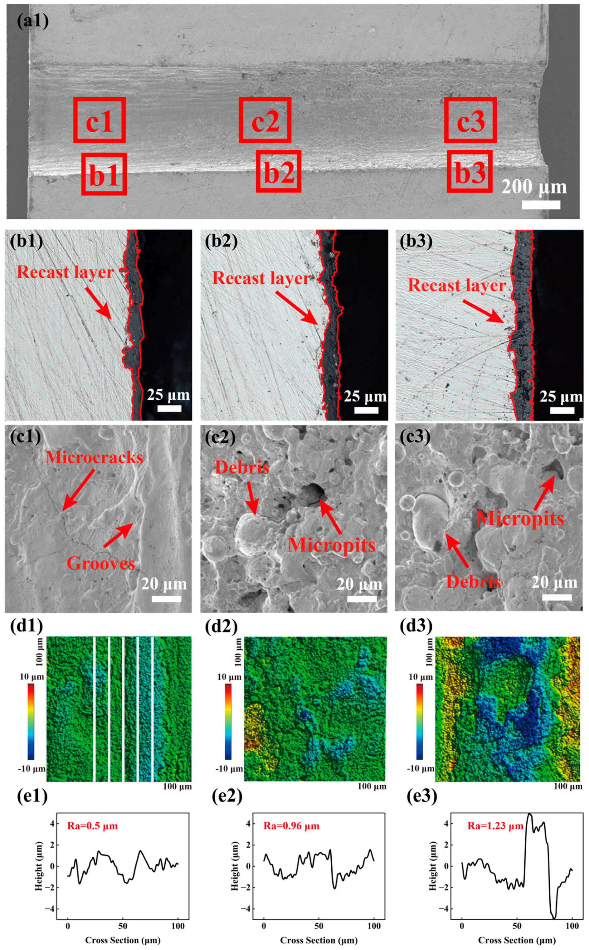
After the specimen was sectioned axially and polished, the inner wall morphology of the hole was observed using SEM and optical microscopy. The overall morphology in Figure 4a shows that the hole wall is straight and regular. The sidewall was examined using a metallographic optical microscope, and the edge contour was extracted through grayscale segmentation. Figure 4(b1–b3) clearly reveal the presence of a thick recast layer on the inner wall surface. At the entrance, midsection, and exit, the recast layer thicknesses are 15.2, 15.9, and 22.0 μm, respectively, with an average thickness of 17.7 μm.
Figure 4. Inner wall morphology of the FCH processed by single-rotary trepanning, with a machine tool motion speed of 5 mm/s and a processing time of 8.4 s. (a1) SEM image of the overall inner wall morphology. (b1b3) Metallographic optical micrographs of the sidewall. (c1c3) SEM images of the inner wall bottom. (d1d3) COM images of the inner wall bottom. (e1e3) Surface roughness profiles corresponding to the areas shown in (d1d3). Here, (1), (2), and (3) denote the hole entrance, midsection, and exit, respectively.
The SEM image in Figure 4(c1) reveals the presence of grooves and microcracks on the inner wall at the entrance. Quantitative analysis using ImageJ 1.54p software shows that over 30 microcracks are distributed on the hole wall, with a maximum length of 264 μm and a maximum width of 0.93 μm. On the inner wall surfaces at the middle and exit sections, extensive micropits and molten residues generated by intense ablation are observed, covering a substantial area of 56,307 μm2.
The three-dimensional morphology of the inner wall at the entrance, midsection, and exit was measured using COM, and the results are shown in Figure 4(d1–d3,e1–e3). During measurement, line profiles were extracted at intervals of 10 μm, and the average value of five such profiles was taken as the surface roughness of the corresponding section. The entrance section exhibits a relatively regular surface with a roughness of 0.5 μm. In contrast, the surface roughness of the midsection and exit sections increases significantly, reaching 0.96 μm and 1.23 μm, respectively. The average roughness of the entire inner wall is 0.90 μm.
FCHs fabricated by single-rotary trepanning exhibit issues such as a thick recast layer, high inner wall surface roughness, and dense microcracks and grooves. These problems arise not only from the inherent significant thermal effects of nanosecond laser processing but also from the specific drilling method employed. First, the speed of the machine tool is extremely low (only 5.0 mm/s), while the laser repetition frequency is as high as 135 kHz, resulting in an average CPC exceeding 1350 per laser spot area, thereby generating a substantial thermal accumulation effect. Second, the cutting kerf formed by single-rotary trepanning is extremely narrow, with an average width of only 71 μm, while the hole depth reaches 3000 μm, giving an aspect ratio as high as 42:1. During the back-ejection process, the ablated material severely scours and adheres to the inner wall, which not only increases the recast layer thickness but also causes grooves and cracks on the surface. As revealed by the cross-sectional view of the kerf, the entrance section features a wider kerf located closer to the hole opening, facilitating the expulsion of ablation debris and thus resulting in lower inner wall roughness. In contrast, the exit section has an extremely narrow kerf situated farther from the hole opening, leading to inefficient debris evacuation and increased adhesion to the inner wall, thereby forming a large number of molten fragments and micropits.
Pronounced oxidation occurred on the surface layer of the inner wall of FCHs machined via single-rotary trepanning. The oxygen contents at the entrance, middle, and exit regions are 33.43 wt.%, 37.59 wt.%, and 32.25 wt.%, respectively, yielding an average content of 34.42 wt.%.

3.2. Optimization of Processing Parameters for FCHs Using Dual-Rotary Trepanning with a Galvanometer and a Machine Tool

To address the issues of thick recast layer and high surface roughness on the inner wall when using machine tool single-rotary trepanning for film cooling holes, this study proposes a combined rotary trepanning method that integrates a galvanometer with the machine tool. This section systematically investigates the effects of parameters including laser focus offset, galvanometer scanning speed, machine tool motion speed, and processing time on drilling efficiency, entrance and exit morphologies, and inner wall quality, aiming to elucidate the process mechanisms and strategies for achieving high-quality and high-efficiency fabrication of FCHs.

3.2.1. The Effect of Laser Focus Offset on Penetration Efficiency

During nanosecond laser drilling of micro-deep holes, the material at the entrance region is readily expelled from the hole via back-ejection, resulting in high material removal efficiency and requiring low laser energy. In contrast, the material at the exit region must travel a longer distance for back-ejection, leading to lower removal efficiency and thus necessitating higher laser energy. To achieve high-efficiency drilling, appropriately shifting the laser focus toward the middle-lower section of the hole can effectively enhance the laser drilling efficiency.
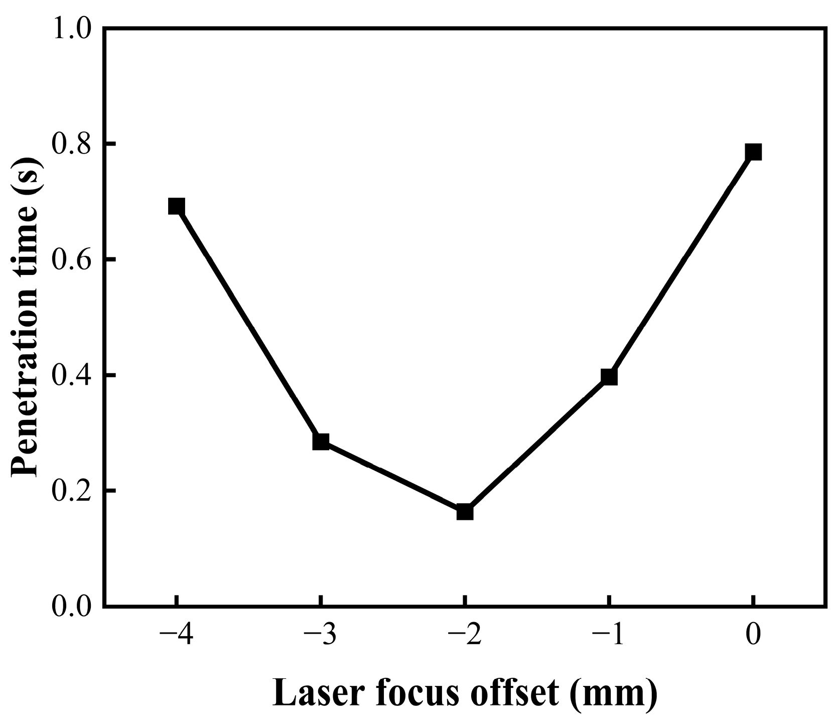
Figure 5 illustrates the effect of focus offset on drilling efficiency within a range of 0 to −4 mm, where −4 mm is defined as the laser focus positioned 4 mm below the upper top surface of the sample. The galvanometer scanning trajectory adopted a full spiral pattern, with a scanning speed of 500 mm/s, a diameter of 0.6 mm, and a line spacing of 0.1 mm. The results show that when the focus offset was 0 mm, the penetration time was 0.786 s. As the focus gradually moved downward, the penetration time continuously decreased. At a focus offset of −2 mm, the penetration time dropped to only 0.164 s, representing a 4.8-fold increase in drilling efficiency. However, when the focus offset was further increased to −4 mm, the penetration time rose to 0.705 s, indicating that the laser focus had deviated from the optimal position. Therefore, the optimal focus offset is determined to be −2 mm.
Figure 5. Laser focus offset dependence of penetration time.
When the laser focus is positioned on the sample surface, the laser energy is primarily deposited in the near-surface region of the material. As drilling progresses into the depth, the combined effects of hole-wall scattering and the increase in spot area lead to a significant reduction in laser fluence, thereby decreasing drilling efficiency. When the laser focus is shifted downward by 2 mm, the enhanced laser intensity at the bottom effectively compensates for the intensity attenuation caused by scattering, facilitating efficient ejection of ablation products from the deep hole cavity and thus improving drilling efficiency [33,62,63]. However, an excessive focus offset increases the spot diameter in the processing region and reduces the laser intensity, while also enlarging the entrance diameter, causing more laser energy to be absorbed and scattered by the hole walls, thereby prolonging the drilling time.

3.2.2. The Effect of Galvanometer Scanning Speed on Penetration Efficiency

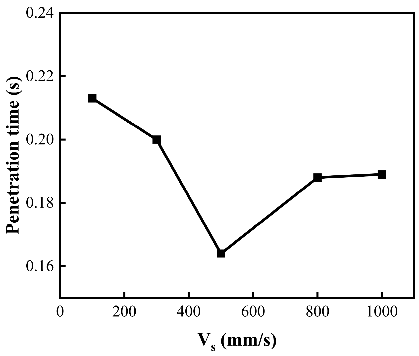
The galvanometer scanning speed is a key parameter that determines the pulse overlap rate during laser processing. The pulse overlap rate affects heat accumulation, ablation product ejection, and plasma shielding, thereby influencing the penetration time, entrance and exit morphologies, and heat-affected zone [60,64]. The galvanometer adopted a full spiral trajectory for processing, with a scanning diameter of 0.6 mm, a line spacing of 0.1 mm, and a focus offset of −2 mm. As shown in Figure 6, when the galvanometer scanning speed increased from 100 mm/s to 500 mm/s, the penetration time decreased from 0.213 s to 0.164 s, representing a 23% improvement in drilling efficiency. However, when the scanning speed exceeded 600 mm/s, the penetration time increased with further increases in scanning speed.
Figure 6. Effect of galvanometer scanning speed on penetration time.
At lower scanning speeds, the pulse overlap rate was high, which facilitated improved ablation efficiency. However, the continuous and intense ejection of ablation products over a very short travel distance prevents their timely expulsion from the narrow kerf, resulting in a strong plasma shielding effect [65]. This effect absorbs a portion of the laser energy and reduces the laser intensity reaching the sample, thereby decreasing the material removal efficiency. At a scanning speed of 500 mm/s, a balance was achieved between laser ablation efficiency and the plasma shielding effect, leading to a high drilling efficiency.

3.2.3. The Effect of Processing Time on FCH Morphology

Figure 7 shows the entrance and exit morphologies of FCHs fabricated by galvanometer drilling under different processing times. Galvanometer drilling enables high-efficiency material removal, achieving perforation within 1.0 s. However, significant defects were observed at the hole exit: the diameter was only 164 μm, the morphology was highly irregular, and the roundness was as low as 0.6. As the processing time increased, the exit diameter rapidly enlarged and the roundness gradually improved. When the processing time varied between 3.4 s and 8.4 s, the entrance and exit diameters stabilized at 635.5 ± 1.3 μm and 320.8 ± 4.7 μm, respectively, with a difference of approximately 315 μm, corresponding to a taper angle of 3.03°. The exit morphologies remained irregular, with an average roundness of only 0.775. These results indicate that FCHs produced by galvanometer drilling alone suffer from issues such as large taper and low exit roundness, making it difficult to meet industrial standards.
Figure 7. SEM images of the entrance (a1d1) and exit (a2d2) morphologies of FCHs fabricated under different processing times. (ad) Correspond to processing times of 1.0, 3.4, 5.1, and 8.4 s, respectively.

3.2.4. The Effect of Machine Tool Speed on the Entrance/Exit Morphologies of FCHs Processed by Dual-Rotary Trepanning

During dual-rotary trepanning processing, the rotation diameter of the galvanometer significantly affected the morphologies of FCHs. When the diameter exceeded 150 μm, the difference between the entrance and exit diameters exceeded 200 μm, resulting in a pronounced hole taper. Conversely, when the rotation diameter was less than 50 μm, the kerf became excessively narrow, leading to an irregular exit edge. Considering the taper, exit circularity, and edge regularity of the FCHs comprehensively, the rotation diameter of the galvanometer was set to 100 μm, and the scanning speed was set to 500 mm/s. The machine tool performed cutting in a circular motion with a diameter of 0.54 mm, while the laser focus offset remained at −2 mm.
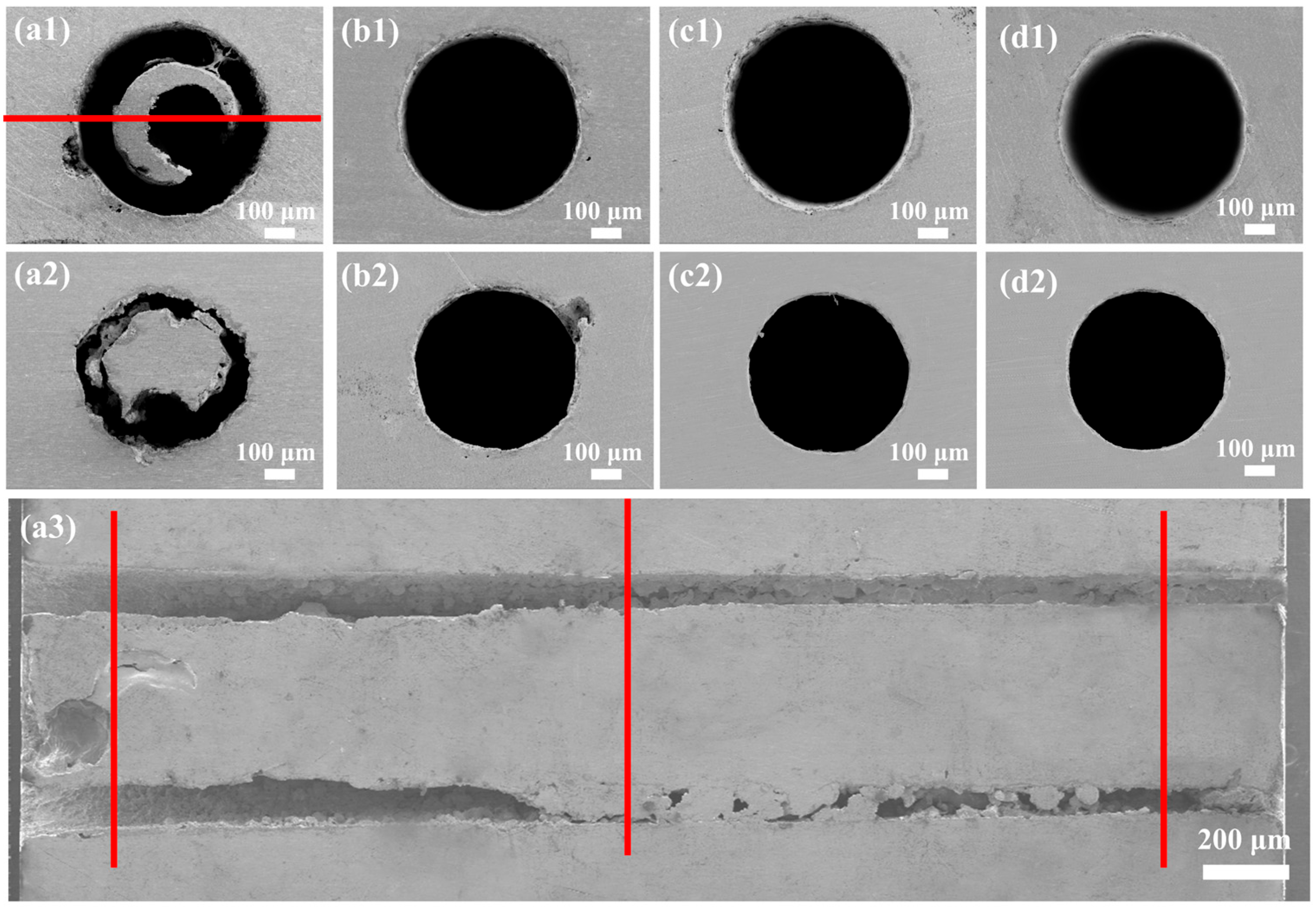
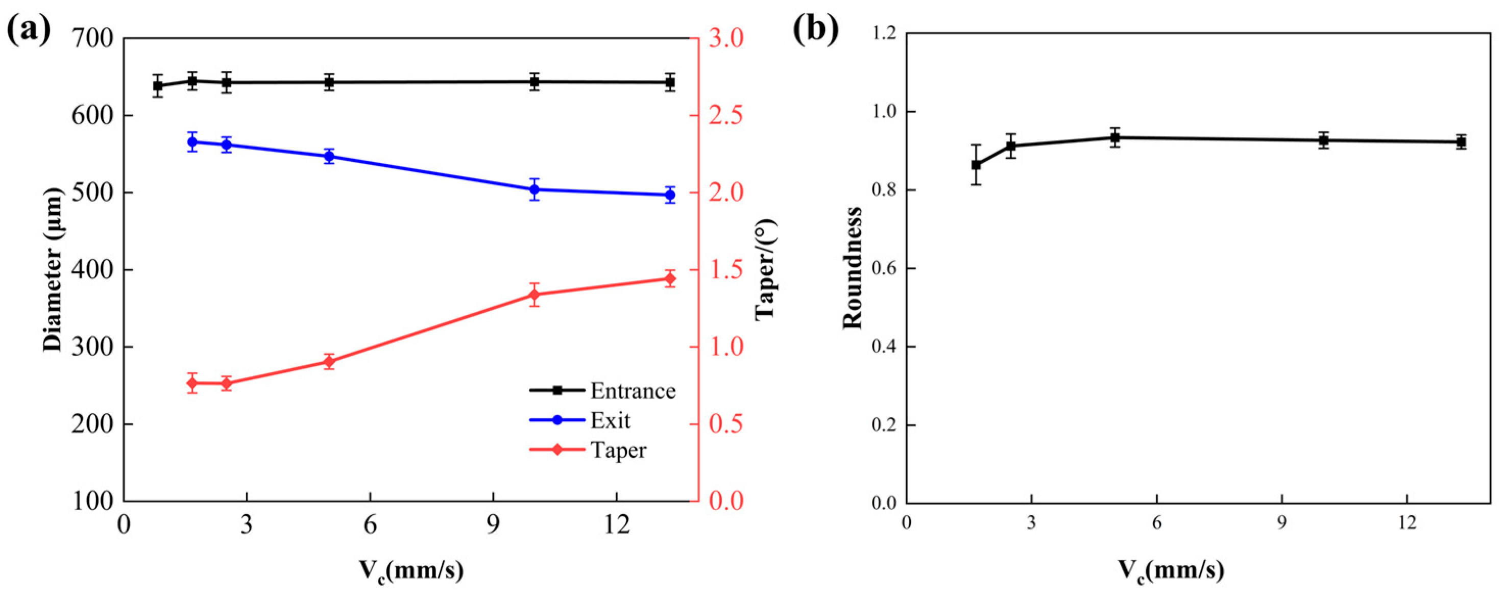
With the processing time kept constant at 6.5 s, the machine tool motion speed was gradually increased from 0.83 mm/s to 13.3 mm/s. The entrance and exit morphologies, diameters, taper, and exit roundness of the FCHs fabricated by dual-rotary trepanning are shown in Figure 8 and Figure 9. At a low motion speed of 0.83 mm/s, the FCH was not completely penetrated due to a decrease in drilling efficiency caused by the intense plasma shielding effect. The cross-sectional image in Figure 8(a3) shows that the kerf widths at the entrance, middle, and exit were approximately 130 μm, 104 μm, and 76 μm, respectively, with an average kerf width of 103 μm, which was 32 μm larger than that obtained with single-rotary trepanning. When the motion speed was increased to 1.67 mm/s, the FCH was fully penetrated, and the exit diameter reached a maximum value of 567 μm, although slight chipping and pits were observed at the exit edge.
Figure 8. SEM images of the entrance (a1d1) and exit (a2d2) morphologies for different motion speeds using dual-rotary trepanning. (ad) Machine tool motion speeds of 0.83, 1.67, 2.5, and 5.0 mm/s, respectively. (a3) The axial cross-sectional image along the direction indicated by the red line in (a1).
Figure 9. Effect of machine tool motion speed on the morphology of FCHs processed by dual-rotary trepanning. (a) Entrance and exit diameters, and taper. (b) Exit roundness.
When the machine tool motion speed was further increased to 2.5 mm/s and 5.0 mm/s, the exit diameters exceeded 540 μm, with a circularity greater than 0.91. Notably, at a speed of 5.0 mm/s, no obvious chipping or pits caused by ablation ejection or thermal damage were observed, and the exit edge was smooth and regular. When the motion speed exceeded 8.3 mm/s, the exit diameters exhibited a decreasing trend. The optimized machine tool motion speed was determined to be 5.0 mm/s.
Compared with single-rotary trepanning, dual-rotary trepanning yields a wider kerf [66], allowing ablation products to expand more fully and reducing the density of the ejected plume, thereby mitigating the impact on the exit edge. The low-density plume is more easily blown away by high-pressure assist gas and undergoes more effective cooling, which alleviates thermal damage effects and results in a more regular and smoother hole morphology, free of significant pits and chipping.

3.2.5. The Effect of Processing Time on the Entrance/Exit Morphologies of FCHs Processed by Dual-Rotary Trepanning

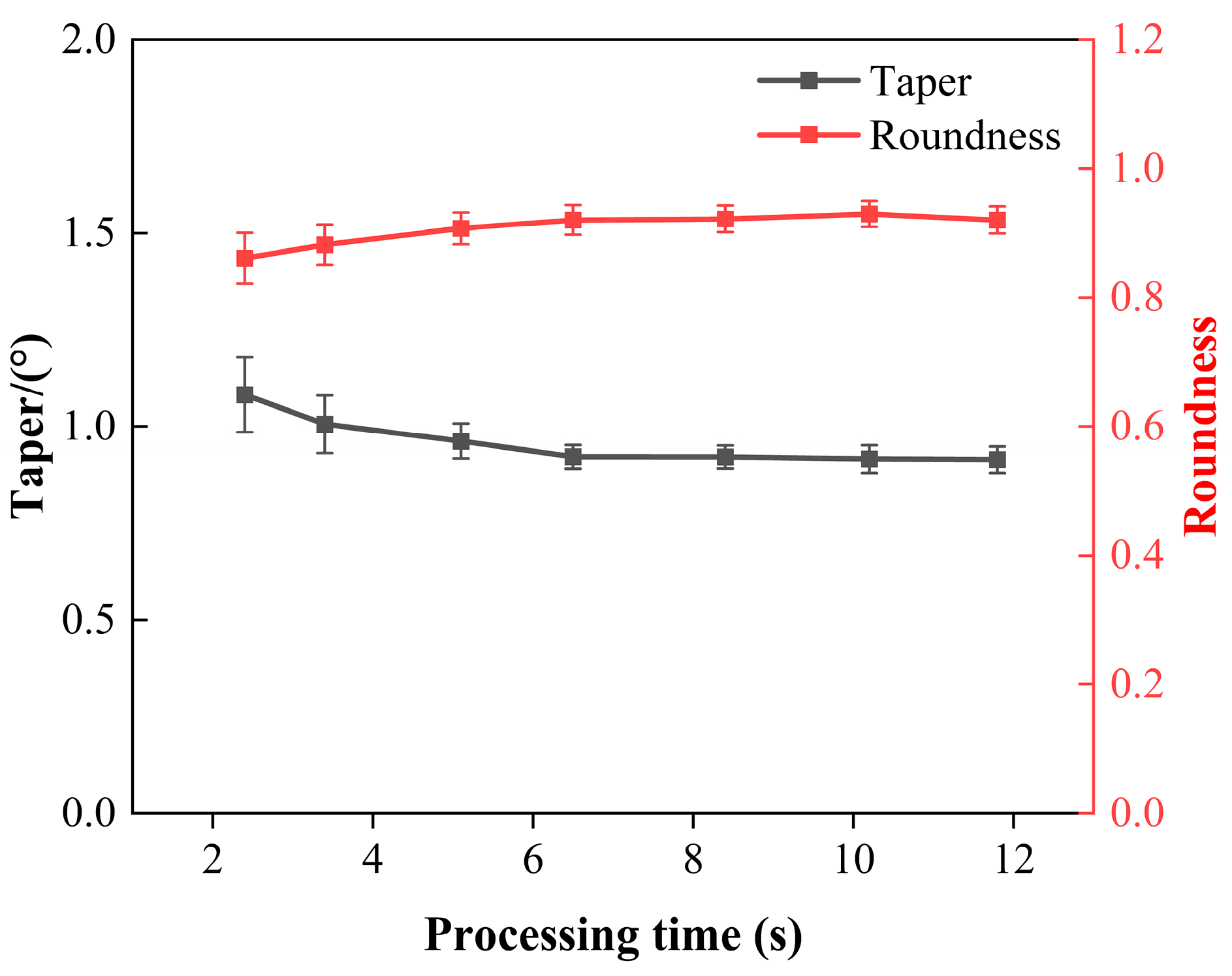
The machine tool speed was set to 5.0 mm/s, and the effects of different processing times on the diameter, taper, and exit circularity of FCHs were investigated, as illustrated in Figure 10. The results show that when the processing time exceeded 2.4 s, complete penetration of the FCHs was achieved, representing a 41% improvement in drilling efficiency compared with single rotary trepanning. This improvement is attributed to two factors. First, the dual rotary trepanning produces a wider kerf, which facilitates the removal of ablated material by the high-pressure assist gas. Second, the higher motion speed reduces the pulse overlap rate, thereby weakening the plasma shielding effect and enhancing the laser processing efficiency. When the processing time exceeded 6.5 s, the exit diameter and circularity reached relatively high levels and tended to stabilize. Considering the processing efficiency, exit morphology, and taper comprehensively, the optimal processing time was determined to be 6.5 s.
Figure 10. Effect of processing time on the morphology of FCHs processed by dual-rotary trepanning.
Following systematic optimization, the processing parameters for FCHs using dual-rotary trepanning were determined as follows: the galvanometer scanning speed was 500 mm/s with a trepanning diameter of 0.1 mm; the machine tool motion speed was 5.0 mm/s with a trepanning diameter of 0.54 mm. The processing time per hole was 6.5 s, and the laser focus offset was set to −2 mm.

3.3. High Quality FCHs Processed by Optimized Dual-Rotary Trepanning

3.3.1. Morphologies of the Entrance/Exit of FCHs

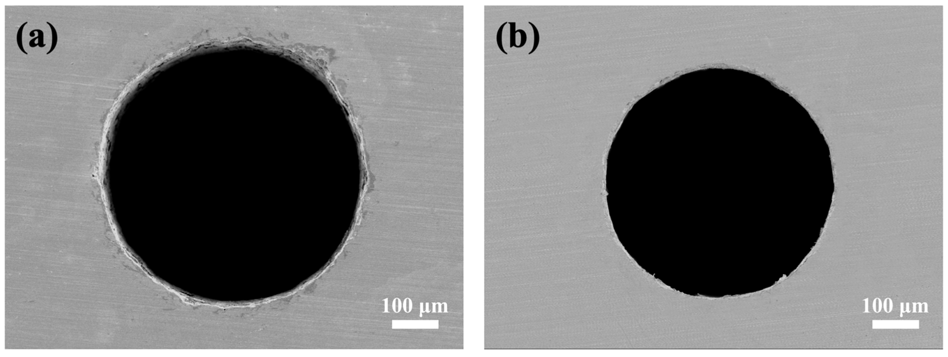
The entrance and exit morphologies of FCHs processed by optimized dual-rotary trepanning are shown in Figure 11. The entrance diameter was 644 μm, and the exit diameter was 547 μm, corresponding to a taper of 0.917°, which is significantly lower than the taper requirement for gas turbine blades. The exit edge is highly regular, with a circularity of 0.951.
Figure 11. (a) The entrance and (b) exit morphologies of an FCH processed by optimized dual-rotary trepanning.

3.3.2. Morphologies of the Inner Wall Surface of FCHs

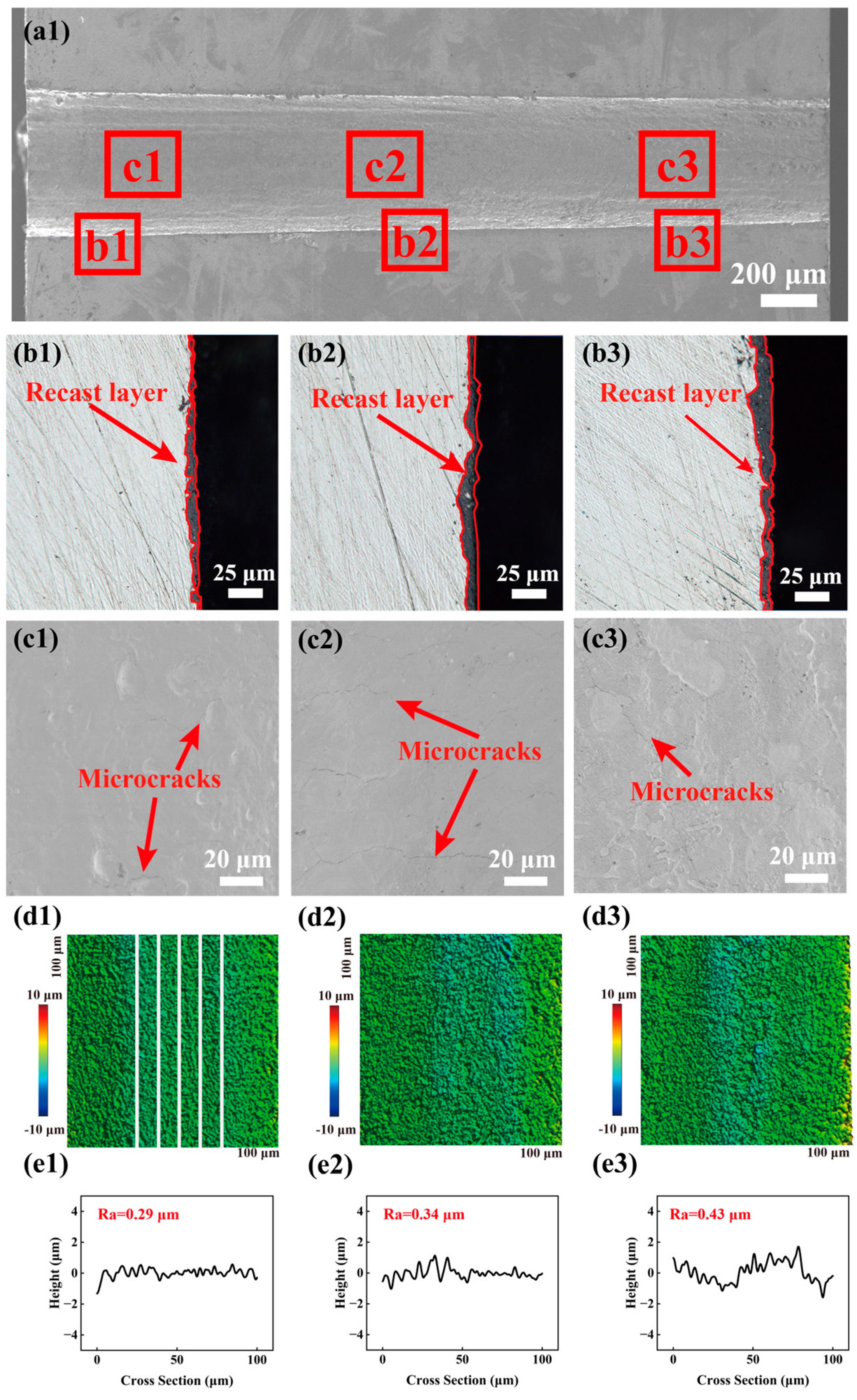
The specimen was sectioned along the axial direction of the FCHs and subsequently polished. The inner wall quality was characterized using SEM and optical microscopy, with the results presented in Figure 12. The overall morphology shown in Figure 11a reveals that the hole walls are straight and well-defined. Observation of the sidewalls using metallographic optical microscopy (Figure 12(b1–b3)) indicates the presence of a thin recast layer on the wall surface. Through grayscale analysis, the boundary between the recast layer and the hole wall (indicated by the red polyline) was extracted, and the recast layer thicknesses at the entrance, middle, and exit were measured as 4.3 μm, 7.0 μm, and 8.8 μm, respectively, with an average thickness of 6.7 μm. Compared with the single-rotary trepanning, the recast layer thickness on the inner wall processed by dual-rotary trepanning was significantly reduced, amounting to only 37.9% of that of the former. SEM images show that the inner wall is smooth and regular. Except for occasional microcracks, no obvious grooves, large-area pits, or slag adherence were observed at either the entrance or exit of the holes. Quantitative analysis using ImageJ 1.54p software revealed approximately 20 microcracks on the hole wall, with a maximum length of 135 μm and a maximum width of only 0.69 μm. The number, length, and width of the microcracks were all significantly reduced compared with those obtained using the single-rotary trepanning.
Figure 12. Inner wall morphology of the FCH processed by optimized dual-rotary trepanning, with a machine tool motion speed of 5 mm/s and a processing time of 6.5 s. (a1) SEM image of the overall inner wall morphology. (b1b3) Metallographic optical micrographs of the sidewall. (c1c3) SEM images of the inner wall bottom. (d1d3) COM images of the inner wall bottom. (e1e3) Surface roughness profiles averaged along five lines with an interval of 10 μm (as indicated in d1). Here, (1), (2), and (3) denote the hole entrance, midsection, and exit, respectively.
The three-dimensional morphology of the inner wall was measured using COM. The results indicate that the inner wall is smooth and regular, with surface roughness values of 0.29 μm, 0.34 μm, and 0.43 μm at the entrance, middle, and exit, respectively, and an average value of 0.35 μm. Compared with the single-rotary trepanning, the inner wall roughness was significantly reduced, amounting to only 38.9%.
Compared with the single-rotary trepanning, the FCHs fabricated using the dual-rotary trepanning exhibited significant improvements in both recast layer thickness and surface roughness on the inner wall. The main reasons are as follows: the galvanometer rotates at a high speed of 500 mm/s, which is considerably faster than the machine tool motion speed of 5 mm/s, reducing the CPC from 1350 to 13.5. This drastic reduction effectively mitigates heat accumulation during laser ablation, thereby decreasing the recast layer thickness. In addition, the rotational motion of the galvanometer increases the kerf width, allowing the ablation products to expand sufficiently as they are carried out of the hole by the assist gas, thereby improving the removal efficiency and reducing debris adhesion. Moreover, the low-density ablation plume causes less impact and scratching on the inner wall during ejection, effectively suppressing the formation of grooves and large-scale damage (such as pits), thus reducing surface roughness.
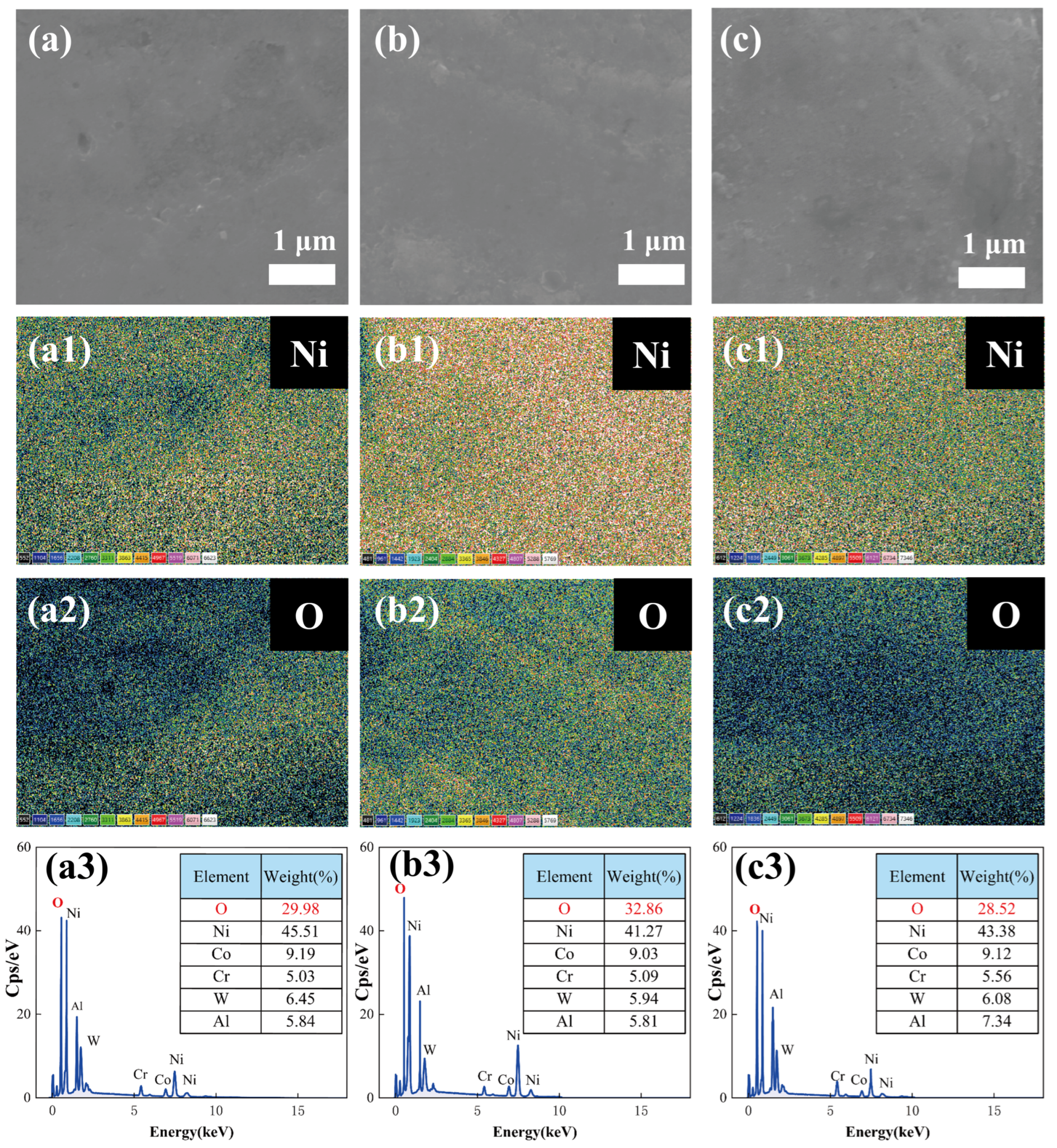
The compositional analysis of the inner wall of FCH after dual-rotary trepanning is presented in Figure 13. The oxygen contents at the entrance, middle, and exit regions are 29.98 wt.%, 32.86 wt.%, and 28.52 wt.%, respectively, with an average value of 30.45 wt.%. Compared with the results obtained from single-rotary trepanning, the oxygen content is slightly lower; however, noticeable oxidation is still observed.
Figure 13. Element analysis of the FCH processed by dual-rotary trepanning. (ac) Local images of the wall surfaces at the entrance, middle, and exit regions, respectively. (a1c1) The EDS scanning results for the Ni element and (a2c2) for the O element, respectively. (a3c3) The EDS analysis.
FCHs processed by single-trepanning and dual-trepanning are summarized in Table 2, as well as some of the representative results from processing by different strategies.
Table 2. A comparative analysis of processing parameters, hole configuration, and quality between this study and previous reports.

3.3.3. Application: Stability and Consistency of FCHs Processed by Dual-Rotary Trepanning

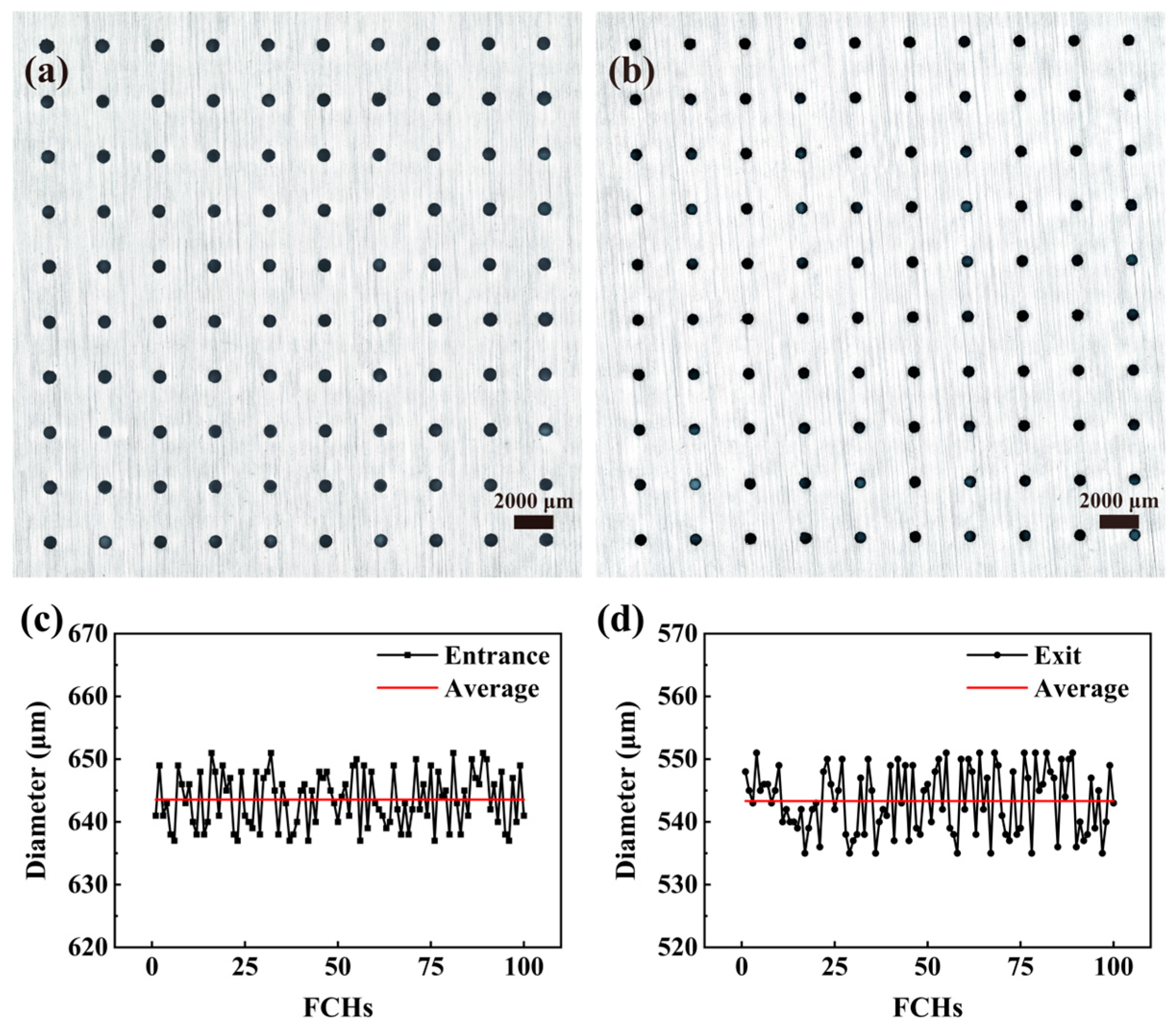
To further investigate the stability and consistency of the dual-rotary trepanning method and the processing system, a 10 × 10 array of FCHs with a spacing of 3 mm was fabricated on a 50 mm × 50 mm × 3 mm plate. Figure 14 presents the overall morphology obtained by automatically stitching together images of the entrance and exit of each hole captured using a 10× optical microscope. The edge contours of the holes were extracted using an image grayscale method, and the hole diameters were obtained by fitting. The results indicate excellent diameter consistency, with entrance and exit diameters of 643.54 ± 4.34 μm and 543.31 ± 5.16 μm, respectively. The exit edges are highly regular, and the roundness exceeded 0.92 in all cases.
Figure 14. The 10 × 10 vertical FCH array. Optical images of entrance (a) and (b) exit. Diameters of (c) entrance and (d) exit.
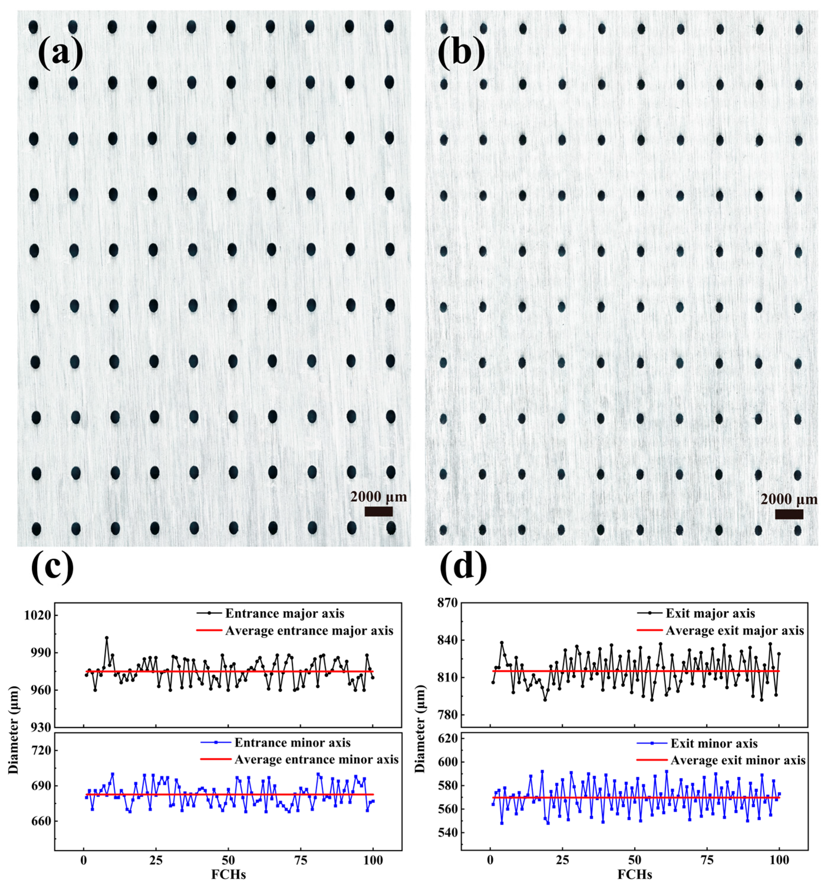
FCHs in turbine blades and combustion chambers are predominantly inclined holes. To further investigate the stability and consistency of the dual-rotary trepanning method for processing inclined holes, a 50 mm × 50 mm × 2 mm plate was tilted at 45° using the A/C rotary table, and a 10 × 10 array of FCHs with a spacing of 3 mm was fabricated. The entrance and exit morphologies are shown in Figure 15. The edges of the holes were highly regular, and the hole diameters exhibited excellent consistency. The major and minor axes of the entrance holes were 974.96 ± 8.85 μm and 682.64 ± 9.24 μm, respectively, while those of the exit holes were 815.17 ± 12.39 μm and 569.76 ± 12.20 μm, respectively. These results indicate that the dual-rotary trepanning method holds good potential for industrial applications in FCH processing.
Figure 15. The 10 × 10 inclined FCH array at a 45°angle. Optical images of (a) entrance and (b) exit. Major/minor axis diameters of (c) entrance and (d) exit.

4. Conclusions

This study proposes a dual-rotary trepanning method using a nanosecond fiber laser and establishes a stable and reliable galvanometer-cradle five-axis machining center, achieving high-quality and high-efficiency FCH machining on DD6 superalloy plates. The main conclusions are as follows:
(1) The effects of parameters such as galvanometer scanning speed, machine tool motion speed, and laser focus offset on processing quality and efficiency were investigated. The underlying mechanisms were analyzed, and parameter optimization was systematically conducted. Using the optimized parameters of a galvanometer speed of 500 mm/s with a rotation diameter of 0.1 mm, and a machine tool speed of 5 mm/s with a rotation diameter of 0.54 mm, a high-quality FCH was fabricated on a 3-mm-thick DD6 plate in only 6.5 s, achieving a processing efficiency significantly higher than the industrial standard (approximately 30 s).
(2) Compared with the results of single-rotary trepanning, dual-rotary trepanning significantly improves the exit quality. The exit edges were smooth and regular, with no obvious defects such as edge chipping or pits caused by the melt ejecta. The roundness is improved to 0.951.
(3) The inner walls were smooth and regular, with no obvious grooves, large-area pits, or slag adhesion. The average thickness of the recast layer was 6.7 μm, which was only 37.9% of that produced by single-rotary trepanning. The average surface roughness was 0.35 μm, which is only 38.9% of that obtained by single-rotary trepanning.
(4) 10 × 10 arrays of FCHs were fabricated on plates with inclination angles of 90° (vertical) and 45°, exhibiting excellent consistency.

Author Contributions

Conceptualization, T.J.; methodology, T.J.; software, K.L.; validation, S.C. and A.H.; formal analysis, M.S. and C.S.; investigation, S.C., C.S., A.H. and K.L.; resources, H.X.; data curation, M.S. and J.Y.; writing—original draft preparation, S.C.; writing—review and editing, D.Z., F.T., T.J. and H.X.; visualization, S.C. and T.J.; supervision, T.J.; project administration, D.Z.; funding acquisition, T.J. All authors have read and agreed to the published version of the manuscript.

Funding

This research was funded by the National Key R&D Programme of China (Nos. 2024YFB4609200, 2021YFA1401100, 2024ZD0706101), National Natural Science Foundation of China (No. 52488301), and ‘Talent Program’ of Henan Academy of Sciences (No. 241823009).

Data Availability Statement

The data provided in this study are available upon request from the corresponding author.

Conflicts of Interest

The authors declare no conflicts of interest.

References

  1. Zhang, H.; Li, P.D.; Gong, X.F.; Wang, T.J.; Li, L.; Liu, Y.J.; Wang, Q.Y. Tensile Properties, Strain Rate Sensitivity and Failure Mechanism of Single Crystal Superalloys CMSX-4. Mater. Sci. Eng. A 2020, 782, 139105. [Google Scholar] [CrossRef] [Scilit]
  2. Wang, T.Y.; Xuan, Y.M.; Han, X.S. Investigation on Hybrid Thermal Features of Aero- Engines from Combustor to Turbine. Int. J. Heat Mass Transf. 2023, 200, 123559. [Google Scholar] [CrossRef] [Scilit]
  3. Gudivada, G.; Pandey, A.K. Recent Developments in Nickel-Based Superalloys for Gas Turbine Applications: Review. J. Alloys Compd. 2023, 963, 171128. [Google Scholar] [CrossRef] [Scilit]
  4. Gong, H.X.; Jiang, R.; Wang, Y.; Liu, Y.X.; Lu, X.P.; Zha, H.Y.; Song, Y.D. Influence of Film Cooling Holes and Thermal Barrier Coating on the Creep Behavior of DD6 Single Crystal Superalloy. Mater. Res. Technol. 2025, 35, 6042–6059. [Google Scholar] [CrossRef] [Scilit]
  5. Yang, Y.Q.; Wen, Z.X.; Zhao, Y.C.; Wang, J.P.; Li, Z.W.; Yue, Z.F. Effect of Crystallographic Orientation on the Corrosion Resistance of Ni-Based Single Crystal Superalloys. Corros. Sci. 2020, 170, 108643. [Google Scholar] [CrossRef] [Scilit]
  6. Xia, W.S.; Zhao, X.B.; Yue, L.; Zhang, Z. Microstructural Evolution and Creep Mechanisms in Ni-Based Single Crystal Superalloys: A Review. J. Alloys Compd. 2020, 819, 152954. [Google Scholar] [CrossRef] [Scilit]
  7. Wu, X.X.; Makineni, S.K.; Liebscher, C.H.; Dehm, G.; Rezaei Mianroodi, J.; Shanthraj, P.; Svendsen, B.; Bürger, D.; Eggeler, G.; Raabe, D.; et al. Unveiling the Re Effect in Ni-Based Single Crystal Superalloys. Nat. Commun. 2020, 11, 389. [Google Scholar] [CrossRef] [Scilit] [PubMed]
  8. Lanzillotta, F.; Sciacchitano, A.; Rao, A.G. Effect of Film Cooling on the Aerodynamic Performance of an Airfoil. Int. J. Heat Fluid Flow 2017, 66, 108–120. [Google Scholar] [CrossRef] [Scilit]
  9. Li, F.; Wen, Z.X.; Wu, Z.Y.; Li, Z.W.; Pei, H.Q.; Yin, Q.; Mao, Q.Z.; Yue, Z.F. The EIFS-Based Fatigue Life Prediction Approach of Nickel-Based Single Crystals with Film Cooling Holes at Elevated Temperature. Int. J. Fatigue 2023, 166, 107272. [Google Scholar] [CrossRef] [Scilit]
  10. Zhang, J.Z.; Zhang, S.C.; Wang, C.G.; Tan, X.M. Recent Advances in Film Cooling Enhancement: A Review. Chin. J. Aeronaut. 2020, 33, 1119–1136. [Google Scholar] [CrossRef] [Scilit]
  11. Zhang, Z.F.; Park, J.; Wang, W.H.; Jiang, R.S.; Lee, M.-G. Crystal Plasticity Study of the Effect of Asymmetric Structure of Diffusive Film Cooling Hole on Heterogeneous Creep and Fracture Behavior of NBSC Superalloy. J. Mater. Res. Technol. 2023, 27, 5041–5058. [Google Scholar] [CrossRef] [Scilit]
  12. Zhang, T.L.; Yuan, H.; Cai, M. Effects of Recast Layer on Fatigue Performance of Laser-Drilled Holes in Nickel-Based Superalloy. J. Mater. Process. Technol. 2023, 311, 117821. [Google Scholar] [CrossRef] [Scilit]
  13. Ebrahimzade, V.; Haasler, D.; Malzbender, J. Failure Mechanism and Lifetime of Various Laser-Drilled APS-TBC Systems under LCF Conditions. Eng. Fail. Anal. 2021, 127, 105526. [Google Scholar] [CrossRef] [Scilit]
  14. Li, Z.W.; Wen, Z.X.; Wang, C.; Dai, Y.; He, P.F. Stress Intensity Factors Analysis for Crack around Film Cooling Holes in Ni-Based Single Crystal with Contour Integral Method. Multidiscip. Model. Mater. Struct. 2024, 20, 18–39. [Google Scholar] [CrossRef] [Scilit]
  15. Cao, N.; Li, X.; Wu, Z.Y.; Luo, X. Effect of Film Hole Geometry and Blowing Ratio on Film Cooling Performance. Appl. Therm. Eng. 2020, 165, 114578. [Google Scholar] [CrossRef] [Scilit]
  16. Gautam, G.D.; Pandey, A.K. Pulsed Nd:YAG Laser Beam Drilling: A Review. Opt. Laser Technol. 2018, 100, 183–215. [Google Scholar] [CrossRef] [Scilit]
  17. Wen, Z.X.; Liang, J.W.; Liu, C.Y.; Pei, H.Q.; Wen, S.F.; Yue, Z.F. Prediction Method for Creep Life of Thin-Wall Specimen with Film Cooling Holes in Ni-Based Single-Crystal Superalloy. Int. J. Mech. Sci. 2018, 141, 276–289. [Google Scholar] [CrossRef] [Scilit]
  18. Sahoo, R.; Kumar, D.; Singh, N.K.; Bajpai, V. Fabrication of Micro-Hole Using Novel Maglev EDM. J. Micromanuf. 2023, 6, 141–150. [Google Scholar] [CrossRef] [Scilit]
  19. Li, Z.K.; Bai, J.C.; Cao, Y.; Wang, Y.Q.; Zhu, G.Z. Fabrication of Microelectrode with Large Aspect Ratio and Precision Machining of Micro-Hole Array by Micro-EDM. J. Mater. Process. Technol. 2019, 268, 70–79. [Google Scholar] [CrossRef] [Scilit]
  20. Wang, Y.F.; Yang, Y.; Li, Y.L.; Shao, F.H.; Zhang, W.W. Profile Characteristics and Evolution in Combined Laser and Electrochemical Machining. J. Electrochem. Soc. 2022, 169, 093505. [Google Scholar] [CrossRef] [Scilit]
  21. Zhang, Z.F.; Mao, Z.; Wang, W.H.; Xie, H.M.; Jiang, R.S.; Xiong, Y.F.; Zhang, X.B. Improving the Fatigue Property of Diffusive Film Cooling Holes in Nickel-Based Single Crystal Superalloy via Ultrashort Pulse Laser Drilling Coupled with Abrasive Flow Machining. J. Mater. Process. Technol. 2024, 328, 118411. [Google Scholar] [CrossRef] [Scilit]
  22. Yang, H.F.; Shen, H. Study on Hole Wall Morphology and Defects in Burst Mode of Femtosecond Laser Drilling. J. Manuf. Process. 2024, 126, 1–11. [Google Scholar] [CrossRef] [Scilit]
  23. Li, M.; Wen, Z.X.; Wang, P.; Liu, Y.X.; Yue, Z.F. Ultrafast Laser Processing of Shaped Film Cooling Holes for Aero-Turbine Blades: Surface Integrity, Parameter Influence and Forming Mechanism. J. Manuf. Process. 2025, 150, 1194–1215. [Google Scholar] [CrossRef] [Scilit]
  24. Sugioka, K.; Cheng, Y. Ultrafast Lasers—Reliable Tools for Advanced Materials Processing. Light Sci. Appl. 2014, 3, e149. [Google Scholar] [CrossRef] [Scilit]
  25. Guo, B.S.; Sun, J.Y.; Hua, Y.H.; Zhan, N.W.; Jia, J.G.; Chu, K.P. Femtosecond Laser Micro/Nano-Manufacturing: Theories, Measurements, Methods, and Applications. Nanomanuf. Metrol. 2020, 3, 26–67. [Google Scholar] [CrossRef] [Scilit]
  26. Wei, T.; Sun, S.F.; Zhang, F.Y.; Wang, X.; Wang, P.P.; Liu, X.H.; Wang, Q.Y. A Review on Laser Drilling Optimization Technique: Parameters, Methods, and Physical-Field Assistance. Int. J. Adv. Manuf. Technol. 2024, 131, 5691–5710. [Google Scholar] [CrossRef] [Scilit]
  27. Marimuthu, S.; Antar, M.; Dunleavey, J.; Chantzis, D.; Darlington, W.; Hayward, P. An Experimental Study on Quasi-CW Fibre Laser Drilling of Nickel Superalloy. Opt. Laser Technol. 2017, 94, 119–127. [Google Scholar] [CrossRef] [Scilit]
  28. Marimuthu, S.; Elkington, H.; Smith, B. Millisecond Fibre Laser Drilling of Thick-Section Aerospace Alloy. Int. J. Adv. Manuf. Technol. 2022, 119, 3437–3447. [Google Scholar] [CrossRef] [Scilit]
  29. Yang, J.; Niu, J.; Chen, L.; Cao, K.Q.; Jia, T.Q.; Xu, H.X. Tunable Simultaneous Bayesian Optimization of Hole Taper and Processing Time in QCW Laser Drilling. J. Manuf. Process. 2024, 109, 471–480. [Google Scholar] [CrossRef] [Scilit]
  30. Huang, Z.C.; Cai, Y.P.; Zhang, Z.W.; Li, N.; Shi, F.; Lin, W.X.; Liu, H.G. Laser Drilling of Micro-Holes with Controllable Taper Using 355 Nm Nanosecond Laser. Opt. Laser Technol. 2025, 181, 111929. [Google Scholar] [CrossRef] [Scilit]
  31. Niu, J.; Yang, J.; Tan, J.Q.; Qin, Z.Y.; Xu, H.X. Reduction of TBC Delamination through a Two-Step Strategy in Nanosecond Laser Drilling of Inclined Film Cooling Holes. J. Mater. Res. Technol. 2025, 36, 7219–7227. [Google Scholar] [CrossRef] [Scilit]
  32. Wang, J.; Zhang, Y.H.; Liu, Y.S.; Fang, H.; Cao, L.Y.; Dong, N.; Luo, R.; Cheng, G.H.; Cao, Y.J.; Zhang, Q. Effect of SiC/SiC Composites Density on Nanosecond-Laser Machining Behaviors. Ceram. Int. 2023, 49, 5199–5208. [Google Scholar] [CrossRef] [Scilit]
  33. Zhang, Z.; Wang, W.; Jiang, R.; Zhang, X.; Xiong, Y.; Mao, Z. Investigation on Geometric Precision and Surface Quality of Microholes Machined by Ultrafast Laser. Opt. Laser Technol. 2020, 121, 105834. [Google Scholar] [CrossRef] [Scilit]
  34. Liu, Y.X.; Wen, Z.X.; Li, M.; Wang, C.; Li, M.; Li, Z.W.; Yue, Z.F. Femtosecond Laser Helical Drilling on Nickel-Based Single Crystal Superalloy: Parameter Influence Laws, Surface Integrity and Formation Mechanisms. Precis. Eng. 2025, 96, 944–962. [Google Scholar] [CrossRef] [Scilit]
  35. Suo, M.Q.; Li, K.; Yang, J.C.; Cao, K.Q.; Xin, M.Y.; Sun, C.W.; Zhang, S.A.; Feng, D.H.; Jia, T.Q.; Sun, Z.R.; et al. High-Performance Processing of Film Cooling Holes with a Picosecond Fiber Laser in DD6 Single-Crystal Superalloy. J. Manuf. Process. 2026, 165, 29–47. [Google Scholar] [CrossRef] [Scilit]
  36. Guo, Z.X.; Lu, X.C.; Paramatmuni, C.; Gao, H.J.; Dunne, F.P.E.; Yan, W.T.; Zhang, Y.-W.; Xu, Y.L. Slip System-Resolved GNDs and SEDs: A Multi-Scale Framework for Predicting Crack Nucleation in Single-Crystal Metals. Acta Mater. 2025, 288, 120853. [Google Scholar] [CrossRef] [Scilit]
  37. Guo, Z.X.; Lu, X.C.; Peng, G.C.; Hu, D.J.; Huang, D.W.; Yan, X.J.; Dunne, F.P.E.; Gao, H.J.; Zhang, Y.-W.; Yan, W.T.; et al. Beyond First-Cycle Damage: Mechanistic Drivers of Fatigue Crack Nucleation in Single Crystals. J. Mech. Phys. Solids 2026, 206, 106393. [Google Scholar] [CrossRef] [Scilit]
  38. Zou, T.T.; Zhao, B.; Xin, W.; Wang, F.Y.; Xie, H.B.; Li, Y.H.; Shan, Y.W.; Li, K.; Sun, Y.B.; Yang, J.J. Birefringent Response of Graphene Oxide Film Structurized via Femtosecond Laser. Nano Res. 2022, 15, 4490–4499. [Google Scholar] [CrossRef] [Scilit]
  39. Gonzalez-Hernandez, D.; Varapnickas, S.; Bertoncini, A.; Liberale, C.; Malinauskas, M. Micro-Optics 3D Printed via Multi-Photon Laser Lithography. Adv. Opt. Mater. 2023, 11, 2201701. [Google Scholar] [CrossRef] [Scilit]
  40. Calvarese, M.; Meyer-Zedler, T.; Schmitt, M.; Guntinas-Lichius, O.; Popp, J. Recent Developments and Advances of Femtosecond Laser Ablation: Towards Image-Guided Microsurgery Probes. TrAC Trends Anal. Chem. 2023, 167, 117250. [Google Scholar] [CrossRef] [Scilit]
  41. Li, K.; Han, R.Z.; Suo, M.Q.; Long, M.Q.; Chen, L.; Cao, K.Q.; Zhang, S.A.; Feng, D.H.; Jia, T.Q.; Sun, Z.R.; et al. High Quality Nanogratings Far beyond Diffraction Limits on Silicon Efficiently Fabricated Using Femtosecond Laser Dual-Beam Interference Direct Writing. Opt. Laser Technol. 2025, 181, 111505. [Google Scholar] [CrossRef] [Scilit]
  42. Sun, X.M.; Dong, X.; Wang, K.D.; Wang, R.J.; Fan, Z.J.; Duan, W.Q. Experimental Investigation on Thermal Effects in Picosecond Laser Drilling of Thermal Barrier Coated In718. Opt. Laser Technol. 2019, 113, 150–158. [Google Scholar] [CrossRef] [Scilit]
  43. Ye, M.Y.; Xiu, H.H.; Ket Thein, C.; Jiang, B.Y.; Zhao, Y.J.; Liu, G.Y.; Nan Li, H. On the Prediction of Hole Geometry in Laser Trepanning Drilling: A Generic 3D Analytical Model Considering Drill System Structure. Opt. Laser Technol. 2024, 177, 111158. [Google Scholar] [CrossRef] [Scilit]
  44. Qin, Z.Y.; Yang, J.; Niu, J.; Chen, L.; Cao, K.Q.; Jia, T.Q.; Xu, H.X. Precision Control of Hole Morphology by Modulating Femtosecond Laser Beam Track with a Four-Wedge Drilling System. Opt. Laser Technol. 2025, 192, 113972. [Google Scholar] [CrossRef] [Scilit]
  45. Li, M.; Wen, Z.X.; Wang, P.; Liu, Y.X.; Li, Z.W.; Yue, Z.F. Femtosecond Laser High-Quality Drilling of Film Cooling Holes in Nickel-Based Single Superalloy for Turbine Blades with a Two-Step Helical Drilling Method. J. Mater. Process. Technol. 2023, 312, 117827. [Google Scholar] [CrossRef] [Scilit]
  46. Bai, J.X.; Huang, K.R.; Xu, Z.W.; Qin, N.; Qian, L.M. An Efficient Near-Zero Taper UV Nanosecond Laser Two-Step Drilling Method for Film Cooling Holes in SiCf/SiC Composites. Opt. Laser Technol. 2026, 197, 114744. [Google Scholar] [CrossRef] [Scilit]
  47. Wang, H.J.; Chen, Q.; Lin, D.T.; Zuo, F.; Zhao, Z.X.; Wang, C.Y.; Lin, H.-T. Effect of Scanning Pitch on Nanosecond Laser Micro-Drilling of Silicon Nitride Ceramic. Ceram. Int. 2018, 44, 14925–14928. [Google Scholar] [CrossRef] [Scilit]
  48. Di, J.; Li, J. Investigation on the Effect of Dynamic Focus Feeding and Widening Path in Nanosecond Laser Drilling. Micromachines 2025, 16, 1081. [Google Scholar] [CrossRef] [Scilit] [PubMed]
  49. Gu, Z.H.; He, Y.Y.; Ji, J.H.; Wei, Y.F.; Fu, Y.H. Reducing the Taper and Heat-Affected Zone in Nanosecond Laser Drilling of CFRP Plate Using Backside Sacrificial Layer. Opt. Lasers Eng. 2025, 185, 108735. [Google Scholar] [CrossRef] [Scilit]
  50. Wang, S.W.; Xie, W.D.; Ding, Y.; Liu, H.; Zhang, X.Y.; Yang, L.J.; Chen, X.; Chen, M.J.; Zhang, W.; Lu, Y.Q.; et al. Investigations on the Water-Jet Guided Laser Drilling Film Cooling Holes on the 8.5 Mm-Thick TBC Superalloy. J. Manuf. Process. 2024, 125, 374–388. [Google Scholar] [CrossRef] [Scilit]
  51. Su, Z.H.; Liu, B.B.; Zhang, Y.L.; Song, J.; Qian, B.; Liu, W.; Sun, S.Z.; Qiu, J.R.; Dai, Y. Precision Processing of Nb-Si Alloy via Water-Jet Guided Laser: Realization of Inhibited-Oxidation and Small-Taper. Opt. Laser Technol. 2025, 187, 112853. [Google Scholar] [CrossRef] [Scilit]
  52. Zhang, C.J.; Wang, P.; Wen, Z.X.; Xu, Z.Z.; He, P.F.; Yue, Z.F. Study on Creep Properties of Nickel-Based Superalloy Blades Based on Microstructure Characteristics. J. Alloys Compd. 2022, 890, 161710. [Google Scholar] [CrossRef] [Scilit]
  53. Long, H.B.; Mao, S.C.; Liu, Y.N.; Zhang, Z.; Han, X.D. Microstructural and Compositional Design of Ni-Based Single Crystalline Superalloys—A Review. J. Alloys Compd. 2018, 743, 203–220. [Google Scholar] [CrossRef] [Scilit]
  54. Chien, W.T.; Hou, S.C. Investigating the Recast Layer Formed during the Laser Trepan Drilling of Inconel 718 Using the Taguchi Method. Int. J. Adv. Manuf. Technol. 2007, 33, 308–316. [Google Scholar] [CrossRef] [Scilit]
  55. Chowdhury, T.S.; Mohsin, F.T.; Tonni, M.M.; Mita, M.N.H.; Ehsan, M.M. A Critical Review on Gas Turbine Cooling Performance and Failure Analysis of Turbine Blades. Int. J. Thermofluids 2023, 18, 100329. [Google Scholar] [CrossRef] [Scilit]
  56. Du, T.H.; Liang, X.Q.; Yu, Y.Q.; Zhou, L.C.; Cai, Z.B.; Wang, L.F.; Jia, W.T.; Pan, X.L. Optimization of Femtosecond Laser Drilling Process for DD6 Single Crystal Alloy. Metals 2023, 13, 333. [Google Scholar] [CrossRef] [Scilit]
  57. Chen, S.S.; Wang, R.J.; Mao, K.L.; Hu, Z.; Wang, B.; Lv, J.; Zhang, W.W. High-Aspect-Ratio Microhole Drilling in MAR-M247 Superalloy Using a Quasi-CW Fiber Laser. Opt. Laser Technol. 2026, 198, 114902. [Google Scholar] [CrossRef] [Scilit]
  58. Sheng, L.Y.; Cheng, X.Y.; Jiang, S.L.; Zhao, C.C.; Liu, J.D.; Jing, C.H.; Wang, J.L.; Xu, L.J.; Xiao, Y.N.; Wang, B.; et al. Investigation on Cutting of CFRP Composite by Nanosecond Short-Pulsed Laser with Rotary Drilling Method. Sci. Eng. Compos. Mater. 2025, 32, 20240047. [Google Scholar] [CrossRef] [Scilit]
  59. Han, Y.J.; Zhang, J.J.; Wang, X.H.; Sun, T. Parametric Optimization of Hole Taper Control in Ultraviolet Nanosecond Laser Micro-Drilling of Copper Foil. Opt. Laser Technol. 2023, 167, 109706. [Google Scholar] [CrossRef] [Scilit]
  60. Schnell, G.; Duenow, U.; Seitz, H. Effect of Laser Pulse Overlap and Scanning Line Overlap on Femtosecond Laser-Structured Ti6Al4V Surfaces. Materials 2020, 13, 969. [Google Scholar] [CrossRef] [Scilit] [PubMed]
  61. Tan, S.; Wu, J.J.; Zhang, Y.; Wang, M.; Ou, Y. A Model of Ultra-Short Pulsed Laser Ablation of Metal with Considering Plasma Shielding and Non-Fourier Effect. Energies 2018, 11, 3163. [Google Scholar] [CrossRef] [Scilit]
  62. Das, D.K.; Pollock, T.M. Femtosecond Laser Machining of Cooling Holes in Thermal Barrier Coated CMSX4 Superalloy. J. Mater. Process. Technol. 2009, 209, 5661–5668. [Google Scholar] [CrossRef] [Scilit]
  63. Wang, R.J.; Wang, K.D.; Fan, Z.J.; Sun, X.M.; Dong, X.; Mei, X.S.; Zhang, W.W. A Comparative Study on High Pulse Energy Femtosecond Laser Drilling of High-Aspect-Ratio Holes under Different Pressure Conditions. J. Manuf. Process. 2023, 85, 492–502. [Google Scholar] [CrossRef] [Scilit]
  64. Fu, Q.; Qian, J.; Wang, G.D.; Zhao, Q.Z. Heat Accumulation Effects in Femtosecond Laser-Induced Subwavelength Periodic Surface Structures on Silicon. Chin. Opt. Lett. 2023, 21, 051402. [Google Scholar] [CrossRef] [Scilit]
  65. Dong, Y.; Shao, P.; Guo, X.; Liu, S.; Zhu, X.; Guo, W. Experimental Study on the Effect of Laser Overlap Rate on the Quality of Femtosecond Laser Machining of Micro-Holes. Opt. Laser Technol. 2024, 177, 111205. [Google Scholar] [CrossRef] [Scilit]
  66. Ouyang, W.T.; Jiao, J.K.; Xu, Z.F.; Xia, H.B.; Ye, Y.Y.; Zou, Q.; Tian, R.Y.; Sheng, L.Y. Experimental Study on CFRP Drilling with the Picosecond Laser “Double Rotation” Cutting Technique. Opt. Laser Technol. 2021, 142, 107238. [Google Scholar] [CrossRef] [Scilit]
  67. Zhu, Q.C.; Fan, P.X.; Li, N.; Carlson, T.; Cui, B.; Silvain, J.-F.S.; Hudgins, J.L.; Lu, Y.F. Femtosecond-Laser Sharp Shaping of Millimeter-Scale Geometries with Vertical Sidewalls. Int. J. Extrem. Manuf. 2021, 3, 045001. [Google Scholar] [CrossRef] [Scilit]
  68. Li, Z.H.; Wang, B.; Cao, Y.; Wang, J.J.; Zeng, Q.Y.; Zhang, Q.L. Investigation of Continuous Wave/Coaxial Waterjet-Assisted Laser Combined Machining of Micro Holes in GH3536. Opt. Lasers Eng. 2024, 181, 108423. [Google Scholar] [CrossRef] [Scilit]
  69. Yu, S.; Zhao, G.Y.; Li, Y.J.; Zhao, Y.G.; Liu, Q. Mechanism and Process Optimization of GH4169 Superalloy Water-Jet Guided Laser Micro-Hole Processing. Opt. Laser Technol. 2025, 192, 113761. [Google Scholar] [CrossRef] [Scilit]
  70. Wang, H.X.; Li, L.; Zhu, S.K.; Xu, Y.; Ren, N.F. Effect of Water-Based Ultrasonic Vibration on the Quality of Laser Trepanned Microholes in Nickel Super-Alloy Workpieces. J. Mater. Process. Technol. 2019, 272, 170–183. [Google Scholar] [CrossRef] [Scilit]
Disclaimer/Publisher’s Note: The statements, opinions and data contained in all publications are solely those of the individual author(s) and contributor(s) and not of MDPI and/or the editor(s). MDPI and/or the editor(s) disclaim responsibility for any injury to people or property resulting from any ideas, methods, instructions or products referred to in the content.

Article Metrics

Citations

Article Access Statistics

Multiple requests from the same IP address are counted as one view.