1. Introduction
Femtosecond lasers, owing to their extremely high machining precision and superior processing quality, are regarded as ideal manufacturing tools and have been widely applied in the fabrication of functional surface structures, biomedical engineering, and related fields [
1,
2,
3,
4]. In the aerospace sector in particular, femtosecond lasers have become the mainstream technology for machining film cooling holes in turbine blades [
5,
6]. Benefiting from the ultrashort pulse duration, femtosecond laser machining minimizes thermal damage to the hole walls, and the thickness of the recast layer is significantly smaller than that produced by electrical discharge machining and other conventional methods [
7,
8]. However, the machining process is affected by the coupling of multiple process parameters, and the final morphology of the film cooling hole depends on a process window that remains insufficiently understood. Therefore, the dependence of film cooling hole quality on femtosecond laser process parameters has attracted extensive attention.
An effective method is to clarify the influence pattern of process parameters on the machining quality of gas film holes through systematic experiments, so as to guide the formulation and optimization of the process [
9,
10]. Recent work further shows that auxiliary-gas selection and blowing pressure can affect hole taper, surface roughness, oxidation, and debris redeposition during femtosecond laser helical drilling [
11]. Liu et al. studied the effects of femtosecond laser power, scanning speed, and other parameters on the taper and drilling efficiency of film cooling holes in a nickel-based superalloy [
12]. They found that laser power has the greatest influence on the entrance diameter and processing efficiency: higher power leads to a larger entrance diameter and higher efficiency. The hole taper is mainly affected by the feed rate and decreases as the feed increases. Based on the influence of parameters, a better combination of process parameters was obtained. Zhang et al. investigated the effects of laser power and rotation speed on the aspect ratio and circularity of film cooling holes and proposed a new two-step drilling process [
13]. In addition to process parameters, researchers have also examined the influence of light source polarization. Fan et al. studied the polarization dependence of penetration efficiency in femtosecond laser drilling, and the radially polarized laser was shown to have the highest penetration efficiency in deep drilling [
14]. These studies provide effective guidance for developing femtosecond laser drilling processes for film cooling holes. However, most research to date has focused on circular holes; studies on other hole types (e.g., irregular or cat-ear-shaped holes) are extremely limited [
15].
In recent years, researchers have found that expanding the hole exit on the blade’s outer surface and combining it with a cylindrical hole to form an irregular hole (comprising the expansion section and straight section) can produce coolant jets with lower momentum and greater surface coverage, thereby greatly improving cooling effectiveness [
16,
17,
18]. Kim et al. systematically simulated the cooling effectiveness of a series of film cooling holes of various shapes (fan-shaped, crescent, dumbbell, etc.), comparing how features such as expansion angle affect performance [
19]. Pei et al. evaluated the low-cycle fatigue life of irregular gas film holes, demonstrating that irregular holes have superior fatigue resistance and service life [
20]. As a result, irregular film cooling holes consisting of an expansion section plus and a cylindrical section have become a developmental trend for turbine blades. Fan et al. preliminarily investigated the effects of key femtosecond laser parameters (e.g., scanning speed) on the hole wall quality of laidback fan-shaped holes, and used response surface methodology for process optimization, reducing the hole-wall roughness to about 0.5 μm [
21]. Thus, femtosecond laser machining also exhibits significant quality advantages for irregular holes. However, studies on femtosecond laser processing of irregular holes are scarce, and no clear correlation between process parameters and machining outcomes has been established. In particular, the effect of defocus distance has been rarely reported.
In this work, a systematic investigation was conducted into the influence of femtosecond laser process parameters on the machining quality of the expansion section of irregular film cooling holes. The effect of defocus distance on the surface microstructure and hole formation during expansion section machining is discussed in detail. Furthermore, the relationship between the surface microstructures (and resulting micro-holes) and the quality of the hole wall was established, forming a complete chain from process parameters to quality.
2. Experimental Procedure
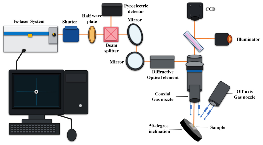
A femtosecond laser system was used with a maximum power of 20 W, a tunable pulse repetition rate from 100 to 700 kHz, a pulse width of 300 fs, a wavelength of 1030 nm, and the pulse energy was set to 40 μJ. The pulse repetition frequency used in this study was 200 kHz. The collimated laser beam was focused onto the workpiece surface using a telecentric F-theta lens with a focal length of 100 mm, yielding a focused spot diameter of approximately 50 μm at the focal plane. A five-axis CNC machine tool provided sample motion (maximum speed 200 mm/s, travel ranges: 1000 mm × 450 mm × 300 mm in X, Y, Z). During femtosecond laser machining, an off-axis gas jet was used to remove ablation debris. To investigate the effect of defocus, the defocus distance was set to +2.5 mm, 0, and −2.5 mm. The schematic diagram of the experimental setup for femtosecond laser drilling is shown in
Figure 1. To precisely regulate the incident energy, a variable attenuator consisting of a half-wave plate and a beam splitter was employed. Concurrently, a fraction of the beam was picked off by a secondary beam splitter and directed to a pyroelectric detector for in situ power monitoring. The drilling process was performed with coaxial gas assist and dynamically captured by a CCD camera.
A fourth-generation single-crystal nickel-based superalloy DD15 was selected as the workpiece material, as it is widely used in modern turbine blades. Irregular cooling holes are typically named according to the shape of their expansion section; in this study, a typical laidback fan-shaped hole was used for experiments. Each expansion section was divided into dozens of slices of varying size and orientation according to the design. Each slice was then scanned by the laser with a linear fill pattern, using a filling spacing of 20 μm. One complete scan of all slices by the femtosecond laser constituted one machining pass. It should be noted that the programmed scanning trajectory defining the outer boundary of the expansion section was kept strictly identical across all experimental groups. Consequently, the overall macroscopic dimensions of the machined area remained constant regardless of the defocus setting, while the variations in laser spot size affected only the microscopic overlap rate, local energy density, and surface micro-morphology. In actual turbine blade manufacturing, multiple passes are usually required for the expansion section to reach the desired shape and dimensions. In this experiment, each expansion section was machined with 8 passes in total. To simulate the actual spatial orientation of the film cooling holes and the turbine blade’s axis during multi-axis manufacturing and service, the sample was tilted by 50° during laser processing. An inclination angle of 30° to 60° is standard in turbine blade designs to ensure optimal film cooling coverage and minimize jet lift-off.
After femtosecond laser machining, the sample was ultrasonically cleaned for 20 min. The surface structures of the expansion section were then examined using a scanning electron microscope (SEM) and a laser scanning confocal microscope for three-dimensional surface analysis.
3. Results and Discussion
3.1. Positive Defocus Machining Process
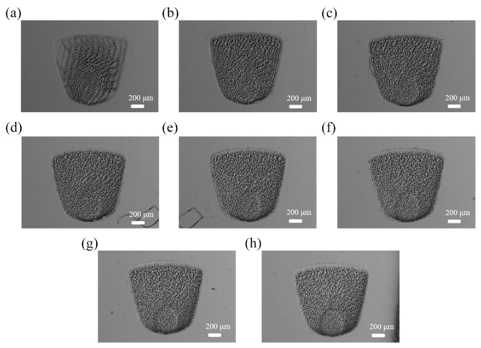
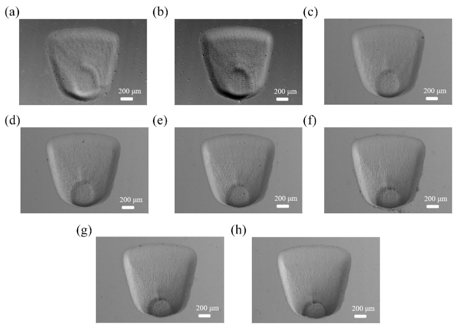
Under a positive defocus of +2.5 mm, multiple-pass machining of the expansion section was performed. The surface morphology results are shown in
Figure 2. After a single pass with positive defocus, a large number of micro-holes formed on the material surface. Notably, during expansion-section machining, the initial micro-holes did not form randomly, but rather appeared in an ordered manner along straight lines at a certain angle, with the central region developing holes before the sides and upper region. This phenomenon is related to the slicing strategy used for the expansion section. Specifically, due to the special laidback fan shape of the LFSH, each slice of the expansion section is a different size to ensure a continuous overall shape. This leads to slight angular offsets at the boundaries between adjacent slices. As shown in
Figure 2a, the straight lines along which micro-holes preferentially formed correspond to the boundary outlines of the slices. With only one pass, the smaller slice regions had already been irradiated once during the scanning of adjacent larger slices, so micro-holes tended to appear first along those slice boundaries. In the interior of the expansion section, the micro-holes had a larger diameter than those near the edges. This is because, during the slicing and scanning process, most slices require laser scanning in the interior area; therefore, the central part of the expansion section receives more laser irradiation overall compared to the periphery. The micro-holes continue to grow and merge with each other, eventually forming conical protrusions.
With further processing of the expansion section, the micro-holes rapidly increase in number. After two passes (
Figure 2b), the entire scanned region is filled with micro-holes, and the machined area has acquired the characteristic laidback fan shape of the LFSH. The micro-holes in the upper region are slightly larger in diameter than those in the lower region. As laser scanning continues over multiple passes (
Figure 2c–h), the processed region gradually achieves the desired final shape: the upper part sees less material removal while the lower part sees more, producing a certain sloped contour. It is precisely this contoured surface that gives the irregular hole its excellent cooling effectiveness. Unlike conventional femtosecond laser machining of a flat surface, here the sample is tilted at 50° during expansion section machining, so the conical features of the expansion section appear different from those produced by perpendicular incidence. In essence, machining on a tilted surface cuts the forming cones at an angle, resulting in the cross-sectional cone profiles visible in
Figure 2h. Between these cones, relatively deep voids remain, and the machined surface exhibits pronounced undulations. Additionally, in the lower circular region of the expansion section (the location of the straight cylindrical segment of the hole), machining is still performed along the axial direction. Under positive defocus, this region is also observed to be covered with micro-holes prior to drilling the straight segment.
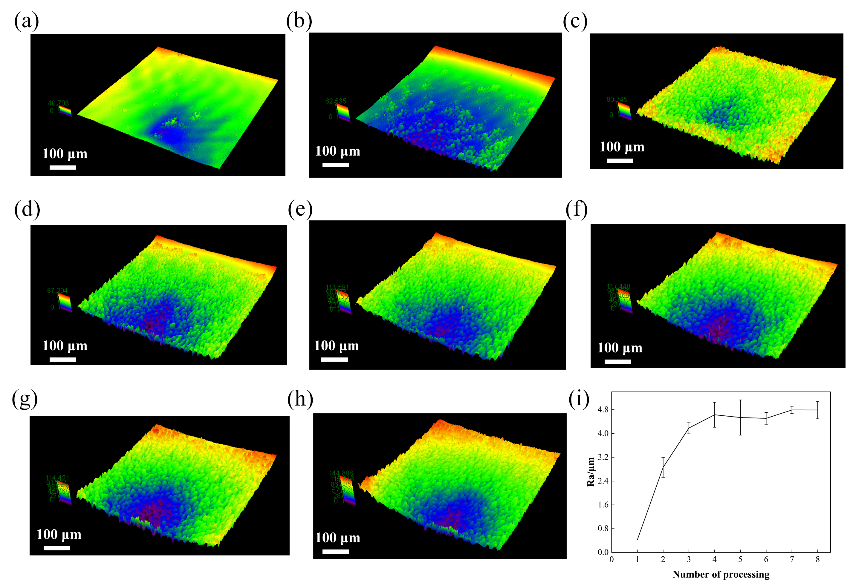
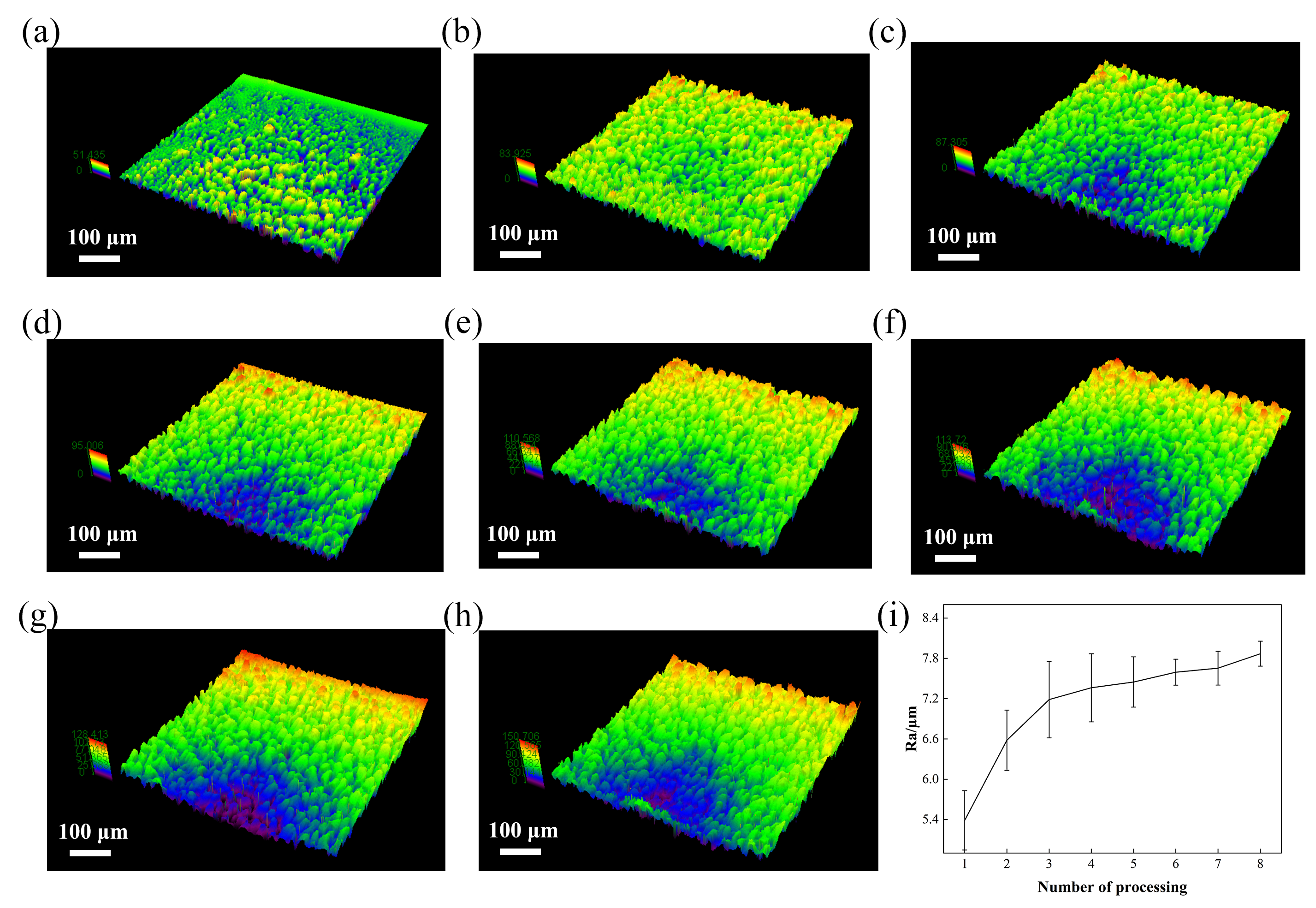
Using the laser confocal microscope, the 3D surface topography of the microstructured expansion section under positive defocus was characterized, as shown in
Figure 3a–h. The location for laser confocal characterization is located in the middle part of the expansion section, with an area size of approximately 600 μm × 600 μm. The color variations in the 3D confocal topographies represent surface height. Specifically, red/yellow colors indicate higher elevated regions (peaks), while blue/purple colors indicate deeper recessed regions (valleys). The height map clearly shows that the formation of micro-holes leads to significant surface relief (peaks and valleys).
Figure 3i plots the surface roughness as a function of the number of passes. After one pass, the roughness is already about 5.3 μm. After two passes, the roughness increases most rapidly, reaching approximately 6.6 μm, which corresponds to the rapid initial growth in micro-hole depth. With further increases in pass count, the roughness continues to rise, reaching about 7.8 μm after 8 passes. This indicates that once micro-holes form, they do not become shallower or disappear with additional scanning; instead, they deepen further with each pass. Such an expansion-section morphology significantly degrades the surface quality. Moreover, during turbine blade service, environmental particulates could become trapped in these micro-holes and, at elevated temperatures, abrade the blade, potentially causing premature failure.
3.2. Zero Defocus Machining Process
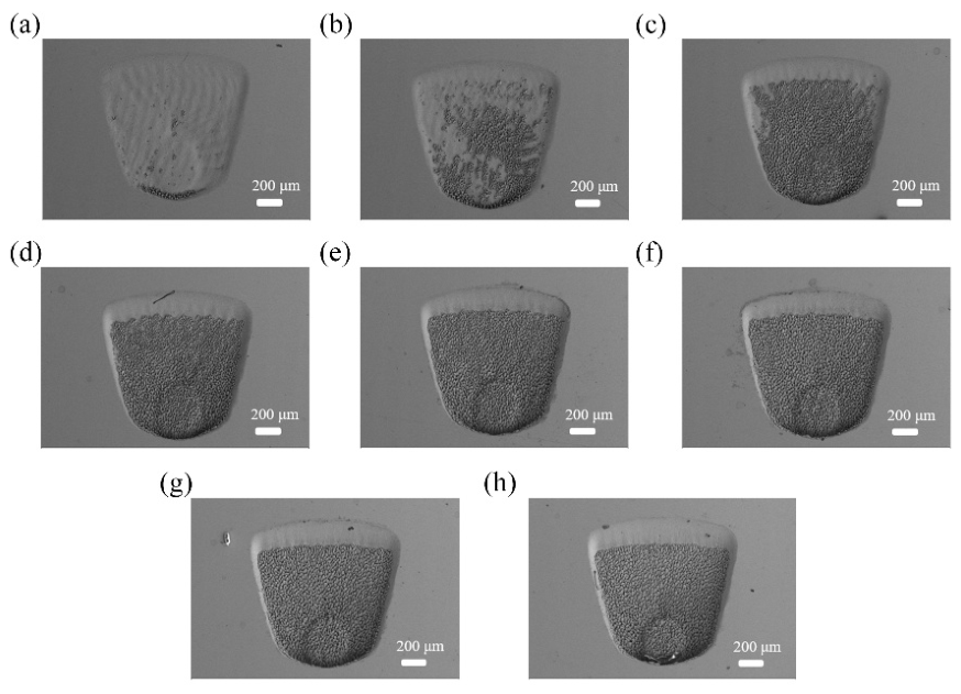
Figure 4 shows the surface morphology of the expansion section after multiple-pass machining at zero defocus (0 mm). After a single pass (
Figure 4a), micro-holes begin to appear on the machined surface, mainly concentrated in the interior and lower regions. As discussed in
Section 3.1, during the scanning of each slice, the interior region receives multiple laser irradiations, so micro-holes tend to form preferentially in those areas. When the defocus is zero, the laser’s focal plane coincides with the surface of the target area. However, because the sample is tilted by 50° during machining, the surface in the lower region is angled at 50° relative to the focal plane. In other words, the focal plane lies above the lower part of the surface, which is equivalent to a positive defocus for that region. Based on the results from the positive defocus case, we know that a positive defocus condition promotes the preferential formation of micro-holes. Therefore, after one pass, the interior and lower regions of the expansion section still develop micro-holes first.
As the number of passes increases to two (
Figure 4b), the micro-holes become more numerous. Similar to the positive defocus case, they form preferentially along straight lines at certain angles, with the interior region still developing first. After further passes (
Figure 4c–h), micro-holes eventually cover the entire scanned area, and their size becomes more uniform. Notably, a portion of the upper region of the machined area did not develop any micro-holes and remains smooth. This is likely because that upper portion, when the sample is tilted, is under a negative defocus condition, so micro-holes do not form and only small surface protrusions are generated. This phenomenon will be discussed in detail in
Section 3.3.
Using confocal microscopy, the 3D surface morphology for zero defocus was obtained, as shown in
Figure 5. After one pass, the surface has only a few micro-holes, and the roughness is only about 0.4 μm; the surface is relatively smooth and meets the requirements for a high-quality finish. However, as the number of passes increases and micro-holes form, the roughness rises sharply, reaching about 4.6 μm after 4 passes. At this point, the roughness appears to peak; over the next four passes, the roughness does not increase significantly further. After 8 passes, the LFSH expansion section has attained the desired shape, with roughness of around 4.7 μm and only small deviations across the surface. Compared to positive defocus machining, zero defocus yields better expansion-section quality. However, the lower cylindrical portion of the hole still ends up covered with numerous micro-holes in the zero defocus case, which could negatively impact the subsequent laser drilling of the straight segment.
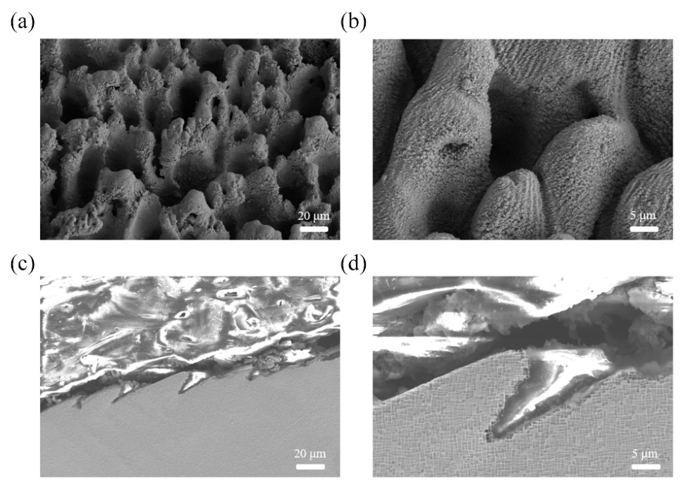
Furthermore, the effect of these micro-holes on other aspects of hole quality was examined.
Figure 6 shows that the top surface of the micro-hole has suffered significant ablation. Periodic ripples are observed on the sloped sides of the cone, and some spherical particles are attached to the surface. These features may be attributed to surface plasmon polaritons (SPPs) excited by the multiple femtosecond laser pulses [
22]. The cross-sectional morphology of the micro-hole is shown in
Figure 6c,d. It can be seen that the micro-hole penetrates about 20 μm into the substrate along the tilt direction, and its width is on the order of 10 μm. It is worth addressing how micro-holes with dimensions of only 1–10 μm are formed under a laser spot diameter of ≥50 μm. This phenomenon is governed by a combination of ultrafast optical energy modulation and geometric waveguiding feedback during multi-pulse processing [
23]. Initially, multi-pulse femtosecond irradiation induces SPP-laser interference and local energy accumulation at overlapping slice boundaries, creating sub-spot-size ripple seeds and micro-pits [
24]. Once these micro-cavities are seeded, subsequent laser pulses undergo multiple internal reflections and light waveguiding along the sloped sidewalls [
25]. This geometric feedback continuously focuses the laser energy down to the cavity apex, driving deep localized ablation and generating high-aspect-ratio micro-holes despite the significantly larger incident beam footprint. This geometry is analogous to a prefabricated crack in the material, which could act as a crack initiation site and significantly reduce the component’s fatigue life. Notably, the sidewalls of these micro-holes (micro-cracks) show no evidence of a recast layer or other thermal damage—this is a distinct advantage of femtosecond laser drilling. The sidewall microstructure remains the original γ/γ′ two-phase structure of the superalloy, with the γ′ precipitates retaining their regular cubic shape and size identical to those in the base material.
In summary, the formation of micro-holes on the expansion section surface not only increases surface roughness, but also creates crack-like defects that extend into the substrate. Therefore, in machining the expansion section of an irregular hole, one should avoid the formation of micro-holes on the surface as much as possible.
3.3. Negative Defocus Machining Process
Figure 7 shows the surface morphology of the expansion section after multiple-pass machining at a negative defocus of −2.5 mm. Strikingly, throughout the entire machining process, no micro-holes are generated. After one pass (
Figure 7a), a shallow honeycomb-like structure appears on the surface. The surface undulation is minimal, and the “cells” of the honeycomb pattern are fairly uniform in size. As the number of passes increases, the outline of the laidback fan-shaped holes becomes gradually clearer, and the lower cylindrical hole region remains relatively smooth and flat. Notably, as shown in
Figure 7h, after 8 passes under negative defocus, the overall depth of the machined expansion section is greater than that achieved under the positive or zero defocus conditions (using the same laser parameters). Comparing the final top-view shapes under the three defocus conditions (
Figure 2h,
Figure 4h and
Figure 7h), it is evident that negative defocusing provides the most well-defined boundary shape for the laidback fan-shaped holes, whereas positive and zero defocusing lead to a highly distorted boundary due to severe micro-hole erosion.
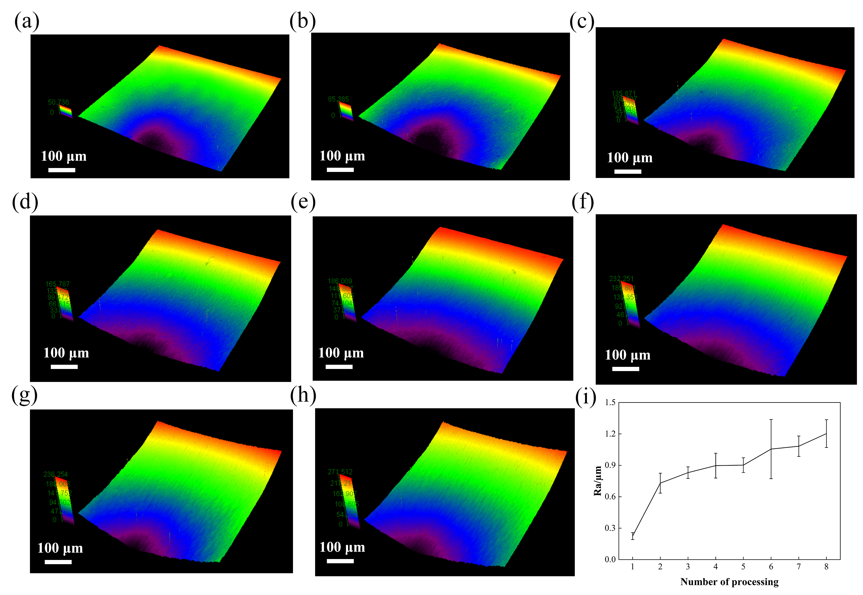
The surface morphology evolution under negative defocus was further characterized with the confocal microscope, as shown in
Figure 8. The roughness values for all passes are plotted in
Figure 8i. Similar to the previous cases, the roughness increases most rapidly between one and two passes. However, under negative defocus, the absolute roughness values remain much lower: after one pass, the roughness is only 0.22 μm, and after two passes, it increases to 0.7 μm. With additional passes, the roughness changes little; even after 8 passes, the surface roughness is only on the order of 1 μm. Additionally, by comparing
Figure 3,
Figure 5 and
Figure 8, the effect of defocus on 3D topography and profile shapes can be analyzed. Under positive and zero defocus (
Figure 3 and
Figure 5), the designed sloped contour of the expansion section is heavily degraded by deep valleys and peaks (surface roughness reaches approximately 7.8 μm and 4.8 μm, respectively), disrupting the smooth slope of the irregular hole. Under negative defocus (
Figure 8): The sloped contour remains smooth and uniform, which closely preserves the designed shape. The overall depth of the machined shape is greater under negative defocus, indicating a more complete and efficient shape formation.
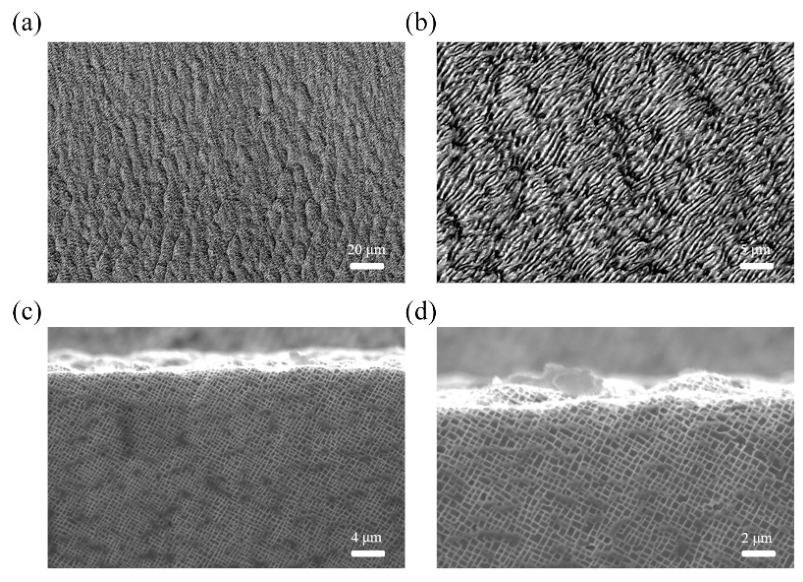
To further examine the outcomes of negative defocus machining, the surface and cross-section of the resulting expansion section were observed, as shown in
Figure 9. After negative-defocus processing, the expansion section surface exhibits a uniform honeycomb-like pattern. At higher magnification, the cell boundaries of this honeycomb structure appear similar to micron-scale ripples, and the entire scanned region is covered with nanoscale periodic ripple structures, i.e., laser-induced periodic surface structures (LIPSS). Such a surface, which has a faint periodic texture but very low relief, is not expected to significantly impair the hole’s performance. Moreover, in practice turbine blades are typically coated after drilling the film cooling holes; this kind of micro-rough surface is actually beneficial for coating adhesion to the substrate. As shown in
Figure 9c,d, the cross-sectional microstructure of the expansion section after negative defocus machining confirms that no micro-holes or crack-like defects are present penetrating into the substrate. The microstructure in the machined region remains a well-defined γ/γ′ two-phase structure with no recast layer, no heat-affected zone, and no other thermal defects.
It is worth noting that simply reducing the laser power at zero defocus to match the peak fluence of the defocused state cannot yield the same uniform, smooth honeycomb-like morphology. This is primarily because, at zero defocus, the smaller spot size (50 μm) restricts the spatial overlap rate to 60%, creating periodic energy modulations that initiate micro-grooves. Additionally, the steeper intensity gradient of the focused beam and its planar wavefront propagation promote localized ablation and waveguiding, which inevitably trigger micro-hole development. In contrast, negative defocusing provides both a high overlap rate (75.6%) and a converging wavefront, which cooperatively suppress localized deep drilling and facilitate uniform surface texturing.
3.4. Relationship Between Surface Microstructures and Hole-Wall Quality
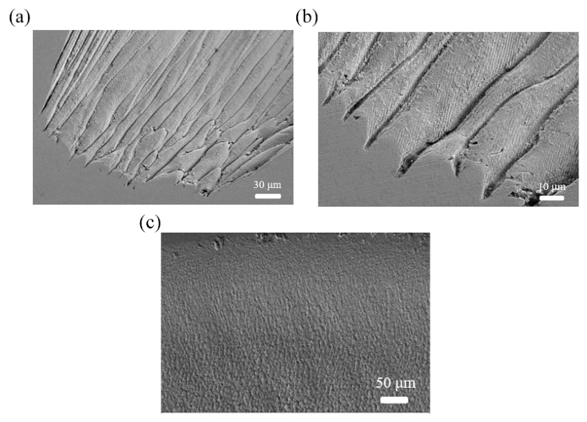
The foregoing discussion has focused on the laser-irradiated surface area of the expansion section. We now consider the quality of the side wall after machining. The morphology of the expansion-section hole wall was characterized, as shown in
Figure 10. When machining the lower part of the expansion section, we observed conical features on the hole wall. Because the sample is tilted at 50° during processing, these cones are oriented obliquely toward the external surface of the material. In addition, a series of relatively deep grooves was found attached to the top of each cone. As the number of passes increased, these grooves gradually evolved into a distinct morphology characterized by a cone at the bottom and a sharp ridge extending upward, as illustrated in
Figure 10a,b. The formation of these ridges on the hole wall can be attributed to the micro-hole structures induced by the femtosecond laser on the surface. However, in the early stages of processing, when the material in the expansion section is being ablated uniformly, no pronounced ridges are formed. The ridges start to appear once the shape of the machined region begins to take form. In particular, for an expansion section geometry that is wider at the top and narrower at the bottom, ridges gradually develop as the surface contour evolves. Although the ridges left by these microstructures do not increase the surface roughness as dramatically as the micro-holes do, their presence still degrades the quality of the hole wall. In fact, the ridges formed in the expansion section can carry over into the subsequent drilling of the straight (cylindrical) section of the hole. The resulting ridges on the wall of the cylindrical hole could introduce stress concentrations during service, potentially accelerating blade failure. Therefore, employing a negative defocus for the expansion section—which avoids the formation of surface micro-holes and hence prevents the generation of hole-wall ridges—is the preferable approach.
4. Conclusions
In this study, the influence of defocus distance in femtosecond laser machining of an irregular film cooling hole’s expansion section was systematically investigated. By progressively increasing the number of laser passes, the evolution of the expansion-section surface microstructures under different defocus conditions was fully revealed. Furthermore, the correlation between the surface microstructures and the formation of hole-wall ridges was established, providing theoretical guidance for femtosecond laser process design for irregular cooling holes. The specific conclusions are as follows:
Different defocus settings lead to distinct surface microstructure morphologies on the expansion section. Under positive and zero defocus, the expansion section surface exhibits an interwoven pattern of conical protrusions and micro-holes. Micro-holes form preferentially in the middle and lower regions of the expansion section and expand with an increasing number of passes until they occupy the entire surface. These micro-holes penetrate into the substrate along the sample’s tilt angle and can act as crack initiation sites during service. In contrast, under negative defocus the expansion section surface remains smooth with a uniform honeycomb-like structure and no micro-holes. The sidewall microstructure of the expansion section is an intact γ/γ′ two-phase structure with no recast layer, no heat-affected zone, and no cracks extending into the base material.
Defocus setting also significantly affects the surface roughness of the expansion section. Under positive defocus, the surface roughness increases continuously with the number of passes, reaching up to 7.8 μm. Under zero defocus, the roughness first rises and then stabilizes; the maximum roughness is about 4.8 μm. By contrast, negative defocus yields the best surface quality—the roughness is only about 0.7 μm.
Under positive and zero defocus, the presence of surface micro-holes in the expansion section leads to the formation of conical features and sharp ridges on the hole wall, which can propagate into the straight segment during subsequent machining. Conversely, under negative defocus, the hole wall is smooth and honeycomb-like, with no detrimental ridges.
Considering surface microstructure, roughness, and hole-wall quality in combination, negative defocus is the optimal choice for femtosecond laser machining of the expansion section of irregular film cooling holes.
Author Contributions
Funding acquisition, Z.Z.; methodology, Z.W. and Z.Z.; software, J.X.; formal analysis, L.W.; writing—original draft preparation, Z.W.; writing—review and editing, Z.Z.; supervision, Z.Z. All authors have read and agreed to the published version of the manuscript.
Funding
This work was funded by Science Research Project of Hebei Education Department (BJ2025185) and Natural Science Foundation of Hebei Province (E2024202066).
Institutional Review Board Statement
Not applicable.
Informed Consent Statement
Not applicable.
Data Availability Statement
The data presented in this study are available on request from the corresponding author.
Conflicts of Interest
The authors declare no conflicts of interest.
References
- Ji, L.; Zhou, B.; Lin, Z.; Sun, W.; Yang, D.; Zheng, T.; Yang, F. Non-reciprocal laser nano-structuring modulation via surface plasmon-polariton backscattering and spontaneous polarization synergy. Nano Res. 2026, 19, 94908885. [Google Scholar] [CrossRef] [Scilit]
- Yin, J.; Lin, Z.; Ji, L.; Hong, M. Femtosecond laser micro/nano-processing via multiple pulses incubation. Opto-Electron. Technol. 2025, 1, 250003. [Google Scholar] [CrossRef] [Scilit]
- Lin, Z.; Ji, L.; Zhou, B.; Sun, W.; Yang, D.; Yang, F.; Yao, T. Energy band structure perturbation induced deviation on precise ultrafast laser nano-structuring. Mater. Today Phys. 2025, 51, 101636. [Google Scholar] [CrossRef] [Scilit]
- Lin, Z.; Ji, L.; Hong, M. Advancing Manufacturing Limits: Ultrafast Laser Nanofabrication Techniques. Engineering 2025, 49, 9–12. [Google Scholar] [CrossRef] [Scilit]
- Zhang, Z.; Liu, S.; Zhang, Y.; Wang, C.; Zhang, S.; Yang, Z.; Xu, W. Optimization of low-power femtosecond laser trepan drilling by machine learning and a high-throughput multi-objective genetic algorithm. Opt. Laser Technol. 2022, 148, 107688. [Google Scholar] [CrossRef] [Scilit]
- Zhang, Z.; Mao, Z.; Wang, W.; Xie, H.; Jiang, R.; Xiong, Y.; Zhang, X. Improving the fatigue property of diffusive film cooling holes in nickel-based single crystal superalloy via ultrashort pulse laser drilling coupled with abrasive flow machining. J. Mater. Process. Technol. 2024, 328, 118411. [Google Scholar] [CrossRef] [Scilit]
- Zhang, F.; Wang, J.; Wang, X.; Zhang, J.; Hayasaki, Y.; Kim, D.; Sun, S. Experimental study of nickel-based superalloy IN792 with femtosecond laser drilling method. Opt. Laser Technol. 2021, 143, 107335. [Google Scholar] [CrossRef] [Scilit]
- Kliuev, M.; Boccadoro, M.; Perez, R.; Bó, W.D.; Stirnimann, J.; Kuster, F.; Wegener, K. EDM drilling and shaping of cooling holes in Inconel 718 turbine blades. Procedia Cirp 2016, 42, 322–327. [Google Scholar] [CrossRef] [Scilit]
- Li, M.; Wen, Z.; Wang, P.; Liu, Y.; Yue, Z. Ultrafast laser processing of shaped film cooling holes for aero-turbine blades: Surface integrity, parameter influence and forming mechanism. J. Manuf. Process. 2025, 150, 1194–1215. [Google Scholar] [CrossRef] [Scilit]
- Dong, Y.; Shao, P.; Guo, X.; Liu, S.; Zhu, X.; Guo, W. Experimental study on the effect of laser overlap rate on the quality of femtosecond laser machining of micro-holes. Opt. Laser Technol. 2024, 177, 111205. [Google Scholar] [CrossRef] [Scilit]
- Liu, Y.; Wen, Z.; Li, M.; Wang, C.; Li, Z.; Li, M.; Yue, Z. A comparative study of auxiliary gases’ effects on film cooling hole machining quality in femtosecond laser helical drilling. Opt. Laser Technol. 2026, 195, 114592. [Google Scholar] [CrossRef] [Scilit]
- Liu, Y.; Wen, Z.; Li, M.; Wang, C.; Li, M.; Li, Z.; Yue, Z. Femtosecond laser helical drilling on nickel-based single crystal superalloy: Parameter influence laws, surface integrity and formation mechanisms. Precis. Eng. 2025, 96, 944–962. [Google Scholar] [CrossRef] [Scilit]
- Zhang, N.; Wang, M.; Ban, M.; Guo, L.; Liu, W. Femtosecond laser drilling 100 μm diameter micro holes with aspect ratios > 20 in a Nickel based superalloy. J. Mater. Res. Technol. 2024, 28, 1415–1422. [Google Scholar] [CrossRef] [Scilit]
- Fan, Z.; Shen, P.; Sun, X.; Sun, T.; Yi, L.; Cui, J.; Mei, X. Evaluation of radially polarized femtosecond laser drilling of film cooling holes. J. Manuf. Process. 2025, 141, 1296–1309. [Google Scholar] [CrossRef] [Scilit]
- Tang, Z.-Q.; Li, Y.-F.; Wang, G.; Yu, Y.; Cao, H.; Li, L.-F.; Jin, Z.-S.; Wang, Y.-L.; Lu, Z. Research advances of femtosecond laser drilling microholes in hard and brittle materials. Opt. Laser Technol. 2025, 185, 112572. [Google Scholar] [CrossRef] [Scilit]
- Tao, Z.; Wang, X.; Xie, G.; Li, H.; Zhou, Z. Effects of structural parameters of laidback fan-shaped hole on film cooling effectiveness on convex surface. Appl. Therm. Eng. 2024, 236, 121636. [Google Scholar] [CrossRef] [Scilit]
- Huang, Y.; Zhang, J.-Z.; Wang, C.-H.; Zhu, X.-D. Multi-objective optimization of laidback fan-shaped film cooling hole on turbine vane suction surface. Heat Mass Transf. 2019, 55, 1181–1194. [Google Scholar] [CrossRef] [Scilit]
- Kang, Y.J.; Park, S.H.; Jeong, J.Y.; Kim, G.M.; Kwak, J.S. The effects of manufacturing tolerance on the film cooling effectiveness of a laidback fan-shaped hole. J. Mech. Sci. Technol. 2022, 36, 2127–2137. [Google Scholar] [CrossRef] [Scilit]
- Kim, S.-M.; Lee, K.-D.; Kim, K.-Y. A comparative analysis of various shaped film-cooling holes. Heat Mass Transf. 2012, 48, 1929–1939. [Google Scholar] [CrossRef] [Scilit]
- Pei, H.; Shi, L.; Ma, M.; Li, F.; Li, Z.; Wen, Z.; Li, Z.; Yue, Z. Fatigue fracture mechanism and life assessment for irregular film cooling hole structures in Ni-based single crystal turbine blades. Eng. Fract. Mech. 2024, 310, 110506. [Google Scholar] [CrossRef] [Scilit]
- Fan, P.; Dong, X.; Wang, K.; Liu, B.; Shen, P.; Yi, L.; Mei, X.; Fan, Z. Optimization of laidback fan-shaped holes machined by femtosecond laser. Int. J. Mech. Sci. 2025, 286, 109874. [Google Scholar] [CrossRef] [Scilit]
- Barnes, W.L.; Murray, W.A.; Dintinger, J.; Devaux, E.; Ebbesen, T. Surface Plasmon Polaritons and Their Role in the Enhanced Transmission of Light through Periodic Arrays of Subwavelength Holes in a Metal Film. Phys. Rev. Lett. 2004, 92, 107401. [Google Scholar] [CrossRef] [Scilit] [PubMed]
- Vorobyev, A.Y.; Guo, C. Direct femtosecond laser surface nano/microstructuring and its applications. Laser Photonics Rev. 2013, 7, 385–407. [Google Scholar] [CrossRef] [Scilit]
- Bonse, J.; Höhm, S.; Kirner, S.V.; Rosenfeld, A.; Krüger, J. Laser-induced periodic surface structures: A Scientific Evergreen. IEEE J. Sel. Top. Quantum Electron. 2017, 23, 9000613. [Google Scholar] [CrossRef] [Scilit]
- Tao, S.; Wu, B.X.; Lei, S.T. Study of laser beam propagation in microholes and the effect on femtosecond laser micromachining. J. Appl. Phys. 2011, 109, 123506. [Google Scholar] [CrossRef] [Scilit]
| Disclaimer/Publisher’s Note: The statements, opinions and data contained in all publications are solely those of the individual author(s) and contributor(s) and not of MDPI and/or the editor(s). MDPI and/or the editor(s) disclaim responsibility for any injury to people or property resulting from any ideas, methods, instructions or products referred to in the content. |