


Abstract
The conventional description of time-varying media assumes that electromagnetic fields evolve according to fixed continuity conditions during parameter jumps. However, recent discussions have made it clear that such continuity conditions are not physical constraints, but are determined by the microscopic processes that underlie the modulation. However, a unified theoretical framework capable of systematically describing different continuity conditions is still lacking. By treating continuity rules as tunable parameters and incorporating them into a unified time-varying theoretical framework, the scope of time-varying metamaterials is expanded to encompass non-resonant reflectionless wave amplification without momentum bandgaps, reversible conversion between propagating waves and static fields, etc. Hence, in this work, wave phenomena previously considered impossible become attainable, opening a new dimension for controlling light–matter interactions through time-varying media.
1. Introduction
Time-varying electromagnetic media, whose material parameters are modulated in time, have attracted growing interest in recent years. Time modulation can exhibit numerous intriguing optical properties and give rise to a variety of exotic phenomena absent in static media, including stationary charge radiation [1], Faraday rotation [2,3], Wood anomalies [4], and anomalous Cherenkov radiation [5]. Among the most significant phenomena are time reflection and time refraction at temporal interfaces [6,7,8,9,10,11,12,13]. When an incident wave encounters a sudden change in material parameters, it typically splits into two counter-propagating waves. Under periodic or disordered modulation, these waves interfere and can form momentum band gaps, leading to the concept of photonic time crystals [5,14,15,16,17,18,19]. Modes inside these gaps may grow exponentially by drawing energy from the modulation, offering a mechanism for wave amplification [5,14,15,16].
Despite experimental challenges, a number of studies have successfully observed time refraction, time reflection, and momentum band gaps [8,9,15,20,21,22]. Research has also been extended to dispersive materials, which are more general and physically realistic [23,24,25]. Yet, in modeling these time-varying dispersive media, the continuity conditions imposed on electromagnetic fields at a temporal jump are typically assumed without question. In reality, how these fields evolve at an interface is determined by the specific physical process that modulates the material [7,26,27]. In Newton’s initial derivation of the speed of sound, the relationship between gas pressure and volume was described using Boyle’s law, which was the only available gas law at the time [28,29]. This led to a discrepancy between his theoretical prediction and experimental measurements [30,31,32]. Similarly, in the context of temporal modulation, the relations governing the field quantities and the modulating parameters should not be implicitly assumed; otherwise, the resulting theory may fail to capture the underlying physical reality. The connection between time modulation and the microscopic mechanism has been studied extensively, both in material models and in microwave circuit experiments [27,33,34,35,36,37,38,39]. However, because the resulting conditions are typically tied to the chosen material model, modulation mechanism, and underlying assumptions, a separate derivation is often required for each physical system. Therefore, once a physically appropriate continuity condition has been determined, how can its electromagnetic consequences be predicted within a common framework? In this work, we treat the physically determined continuity condition as a macroscopic input and represent it through the corresponding polytropic indices. We develop a general theoretical framework that incorporates the effects of different continuity conditions. This approach separates the material-specific determination of the continuity condition from the general prediction of field evolution, temporal scattering, band structures, and mode conversion. Furthermore, we demonstrate that mixed conditions are not merely a modeling refinement, but a pathway to new physical phenomena. Circuit constructions are further introduced to demonstrate how selected continuity conditions can be combined and potentially implemented in dynamic transmission lines and time-varying electromagnetic metasurfaces. Our work thus introduces a new degree of freedom to the study of time-varying electromagnetic media, paving the way for future experimental explorations and applications.
2. Theoretical Framework for Continuous Parameter Modulation Cases
We begin with the electromagnetic field equations for static dispersive media and subsequently generalize them to the temporally varying case.
where is the magnetic field, is the electric field, t is time, and is the background permittivity. is the applied current source, and is the polarization current density, which characterizes the material dispersion and satisfies , where the dot denotes the time derivative. We can further write the equation for polarization as [10,23]
denotes the electron mass, represents the collision frequency, is the resonance frequency, and is the plasma frequency.
For temporally varying material parameters, the electric field can be expressed as , where is the spatial coordinate, and collectively represents the set of time-varying parameters (e.g., in Equation (1) and in Equation (2)). The total time derivative of the electric field, accounting for both field variations and parametric changes, can then be written as follows:
where here, and throughout, an overdot denotes the total time derivative. The operator denotes the partial derivative with respect to , while keeping t and all other parameters (with ) fixed, i.e.,
This differential describes a polytropic process, which we define here as a scenario where no internal energy exchange occurs within the wave system, and all energy variations arise solely from external modulation. Substituting Equation (3) into Equation (1) gives the evolution equation for the electric field under temporal parameter variation:
In the dispersion-free case where , and assuming remains temporally continuous during a permittivity jump (), we obtain the following:
Combining Equation (6) with Equation (5) recovers the conventional form of the field equations widely used to describe electromagnetic behavior under permittivity modulation. It can be seen that corresponds to the continuity of the electric field, whereas corresponds to the continuity of the electric displacement field—the scenario most extensively studied in conventional works. Here, is referred to as the polytropic index of the process. At , the system becomes adiabatic, and no energy growth of waves can be drawn from the modulation (see Supplementary Materials). More generally, is governed by the microscopic details of the modulation process. The condition for the discontinuity of the electric displacement vector can be satisfied in the transmission line model. In optical materials, however, this implies the introduction of a time-varying external current and thus requires carrier injection [7,40].
When considering dispersive materials, we can express the polarization field as , with its time derivative given by Similarly, current density has the form , whose derivative is Thus, we can express the evolution of in the time-varying form as
In a lossless Drude-type dispersive medium, the total energy density stored in the electromagnetic fields and the polarization current can be written as The electromagnetic energy density satisfies the Poynting theorem
Using and , the evolution of the total energy density is obtained as
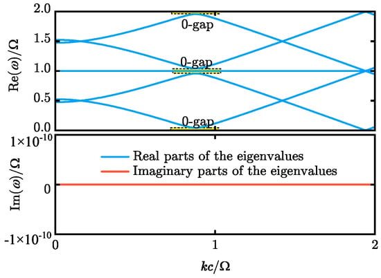
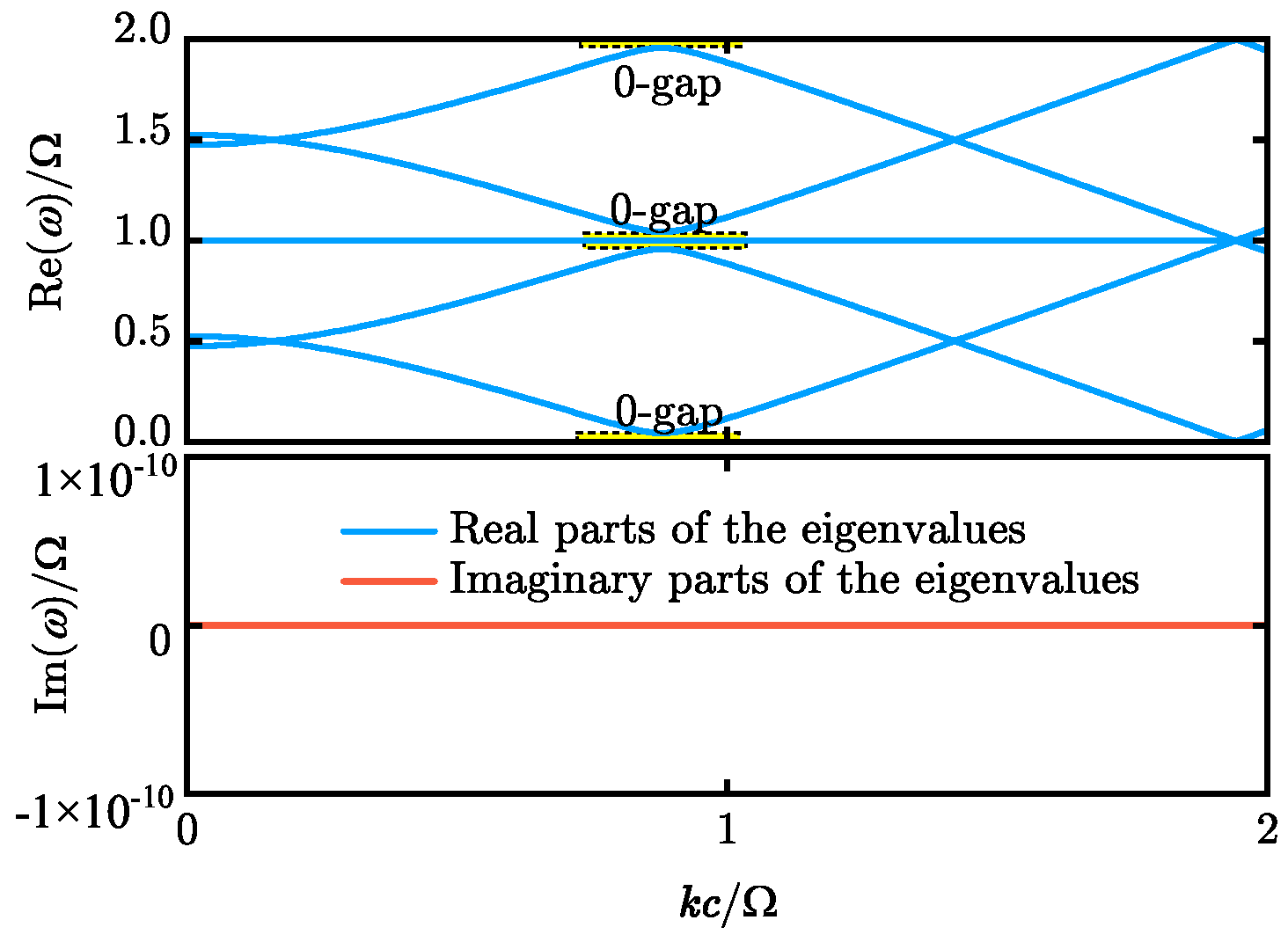
where in the lossless Drude case. Differentiating the polarization-current energy produces the term . This term exactly cancels the power-transfer term in Equation (8), leaving only the work associated with the modulation of . Hence, if is assumed to be continuous in time (), no energy can be drawn from the system, and consequently no momentum band gap opens under temporal modulation. In Figure 1, we plot the band structure for plasma frequency modulation under this continuity condition, with as shown. Here, is the modulation frequency. Using the differential system in Equation (7), we expand all electromagnetic and material-field components, periodically varying material parameters, and continuity-dependent coefficients in Fourier–Floquet series (see Supplementary Materials). Substitution of these expansions converts the differential equations into an algebraic Floquet eigenvalue problem. The band structures are obtained by diagonalizing the resulting truncated Floquet matrix. For more details on this method and its convergence properties, please refer to our previous research [41]. It is observed that, even in the presence of modulation, neither a momentum band gap nor an imaginary part of the eigenvalues appears. In the yellow-shaded region of Figure 1, however, an energy band gap is opened by the temporal modulation. Such a gap is not typically observed in the conventional time photonic crystal; instead, it resembles a 0-gap in Floquet systems [42,43]. It should be emphasized that this 0-gap does not arise from a time-averaged Hamiltonian (the time-varying part averages to zero) but rather from a resonance-induced band anticrossing.
Figure 1.
Real and imaginary parts of the time-modulated Drude dispersive medium for the continuity condition, with band gaps indicated.
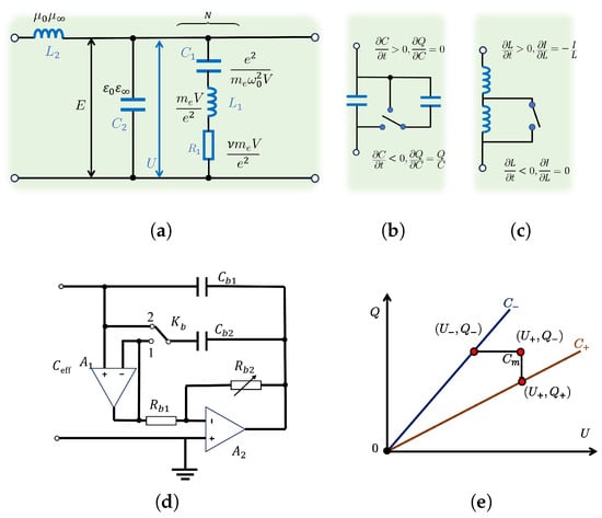
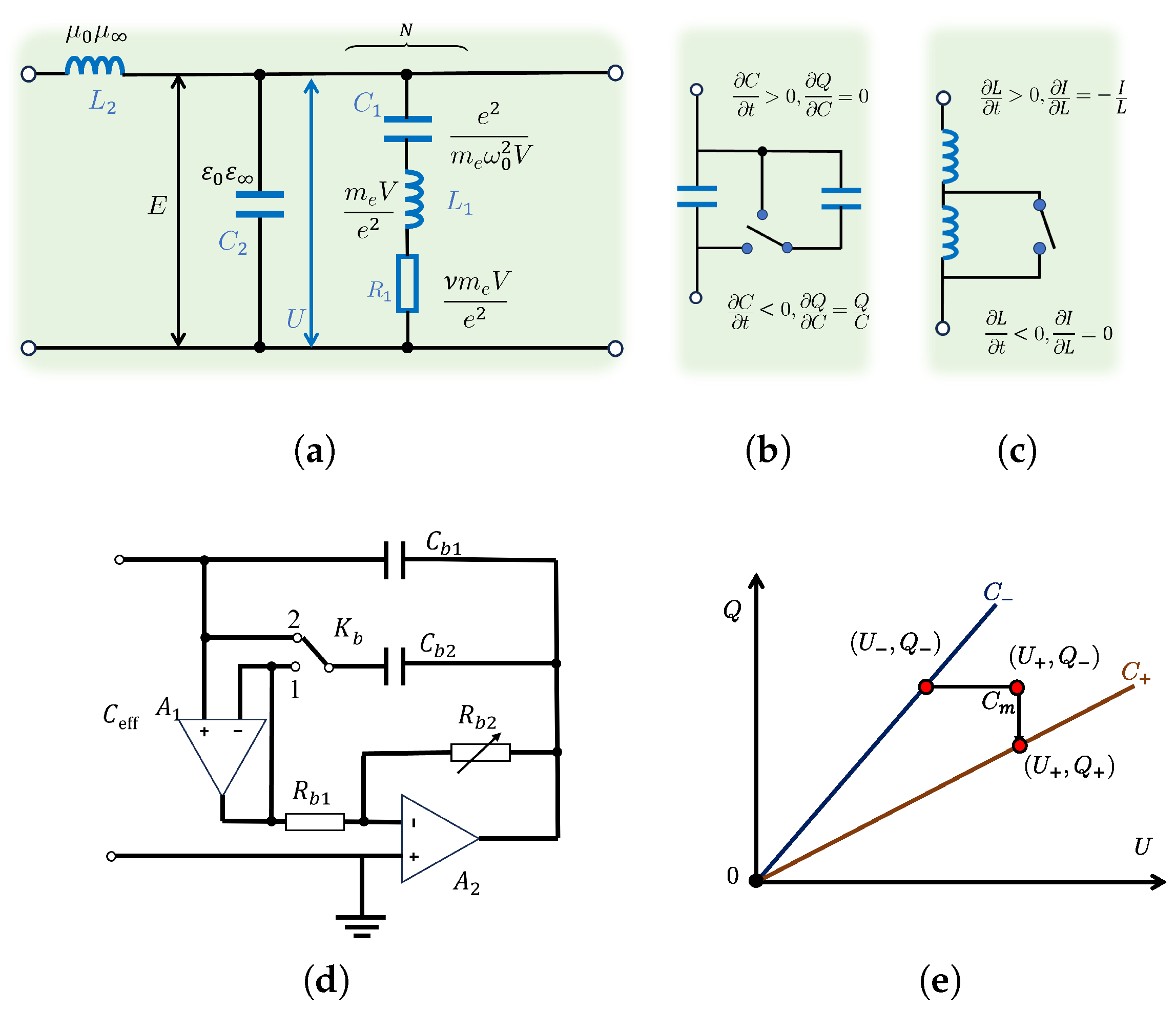
In our method, the additional terms describe different continuity conditions for the electromagnetic parameters, offering a new degree of freedom that allows for novel physical effects. To intuitively illustrate these continuity conditions, we develop a lumped-element circuit analogy, as illustrated in Figure 2.
Figure 2.
Analogical model for time-modulated material dispersion response. (a) Transmission line model. (b) Passive modulation of capacitance. (c) Passive modulation of inductance. (d) Practically realizable capacitance modulation circuit based on operational amplifiers. Adjusting the ratio of to tunes the equivalent capacitance while keeping the charge constant. Meanwhile, toggling switch connects and in parallel, enabling a voltage-conserving capacitance change, and vice versa. (e) Schematic representation of the decomposition of a capacitance jump from to in charge-voltage state-space into a charge-conserving step and a voltage-conserving step, illustrating how the two elementary operations can be combined to realize a general continuity condition.
Figure 2a illustrates a transmission line model where the distributed shunt capacitance of the circuit corresponds to background permittivity , and the voltage U across its terminals corresponds to E. is the distributed series inductance. On the right side, N-series resonant shunt branches are connected in parallel, with the values of , , and corresponding to , , and , respectively. Here, N is the number of oscillators in a representative volume V, and is the corresponding number density. Figure 2b,c illustrate passive modulation schemes for capacitors and inductors. The modulation of a time-varying capacitor can proceed under a constant terminal voltage U, a constant charge Q, or an intermediate condition between these two extremes. For a time-varying inductor , modulation can preserve a constant current I, a constant flux linkage (i.e., the product of current and inductance), or a state between these two. In the passive modulation case, reversing the modulation direction gives rise to different continuity conditions. Consequently, the electromagnetic wave cannot draw energy from the modulation and, consequently, exhibits pure attenuation.
To illustrate the idea of mixed continuity, we introduce a physically realizable circuit model, which provides a platform for constructing temporally modulated metamaterials and metasurfaces. Depicted in Figure 2d is an operational-amplifier-based capacitance-multiplying circuit. We denote the switch-controlled capacitance connected to the non-inverting input of operational amplifier by . Its value is selected by switch : at position 1, whereas at position 2. When , the input impedance is equivalent to a capacitance . The magnitude of this equivalent capacitance can be modified by varying while the charge on it remains invariant during the tuning process. Meanwhile, capacitor , being grounded at one terminal, draws current from the source so as to maintain a voltage identical to that across . Consequently, upon toggling the switch , the equivalent capacitance changes while the voltage across it remains constant. Together with the charge-conserving capacitance tuning achieved by varying the resistance ratio, the circuit in Figure 2d provides two elementary capacitance-modulation operations: one conserving charge and the other conserving voltage. These two elementary operations can be composed to synthesize more general mixed continuity conditions. Figure 2e illustrates this composition in the charge-voltage state space. When the capacitance undergoes a jump from to with the constraint , the process can be decomposed into two distinct capacitance modulation stages: a charge-conserving transition from to intermediate state , followed by a voltage-conserving transition from to , as depicted in Figure 2e. Since the charge and voltage in the transmission-line analogue correspond to D and E, respectively, composing these two elementary operations enables the realization of specific mixed continuous conditions between the continuity of D and that of E. This framework is not restricted to the capacitive example but represents a general strategy applicable to the modulation elements in the equivalent circuit of Figure 2a. Such generality enables a broad class of mixed continuity conditions to be systematically engineered in time-varying electromagnetic systems.
As a specific example, we consider the modulation of , assuming to be continuous during the decreasing half-cycle of and assuming to be continuous during the increasing half-cycle. That is to say, . Here, is the step function. We then obtain
The coefficient of the term appearing here represents the modulation-induced energy dissipation. In fact, much of the physical effects resulting from the mixed continuity conditions are attributable to the influence of the time-varying losses induced thereby.
In our model, we use the modulation frequency as the normalization frequency unit, and we set the square of the plasma frequency to . The modulation of the resonance frequency is expressed as , where is the modulation depth and is set to .
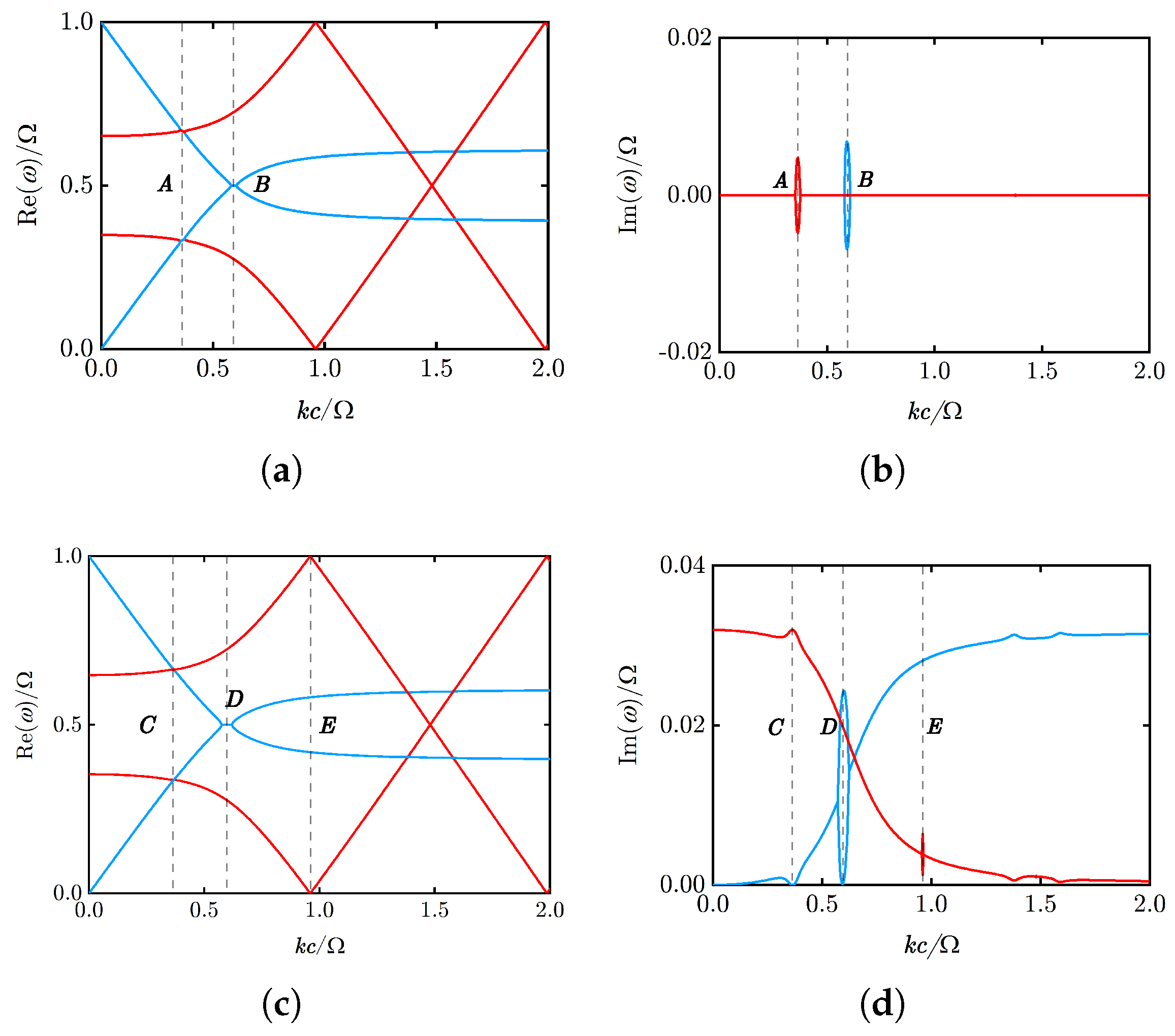
We first calculate the band structure under the assumption of continuous (i.e., ) in Figure 3a,b, where . Here, k is the wave number. A harmonic time dependence is adopted. The blue and red curves in Figure 3a,b are the modulated energy bands that originate from the first and second bands of the static dispersion, respectively. In this conventional scheme, the modulation can induce exponential growth of the modes. Two momentum gaps can be observed in the figure, appearing at two distinct momentum positions, A and B.
Figure 3.
Band structure under modulation. The real parts (a) and imaginary part (b) of the energy band under traditional modulation approach, i.e., . The real parts (c) and imaginary part (d) of the energy band under passive modulation approach. Vertical dashed lines mark the characteristic momentum positions discussed in the text.
As a comparison, the band structure under the proposed passive modulation is plotted in Figure 3c,d. The passive modulation considered below is based on the capacitor-switching operation illustrated in Figure 2b. Connecting an initially uncharged parallel capacitor conserves charge, corresponding to continuous P when decreases. Conversely, disconnecting a charged parallel capacitor preserves the terminal voltage, corresponding to continuous when increases. Both operations can be performed using switches, thus there is no active energy injection into the wave system. Under the passive modulation considered here, the imaginary parts of the lower (blue) and upper (red) bands no longer overlap in the low-k region, in contrast to their behavior under the conventional modulation shown in Figure 3b. In fact, this implies that the passive modulation scheme introduces an effective static loss analogous to . However, this introduces an energy dissipation associated with the electric polarization field rather than the current density field . This originates from the zero-frequency component of the coefficient of in Equation (10). The time derivative term becomes significant at higher modulation frequencies, which extends beyond the conventional temporal modulation framework.
The real parts of the bands in Figure 3a,c remain largely similar, and the principal effect of the passive modulation appears in the imaginary spectrum in Figure 3d. At low k, the first band deviates further from the resonance frequency, so the energy is primarily stored in the electric field. In contrast, the second band lies closer to the resonance frequency, where energy is mainly transferred between the polarization field and the current density field, thereby resulting in greater loss. At point D, the intersection of the same first band at different orders results in a behavior analogous to a conventional momentum band gap. However, the difference is that a pair of modes degenerate in their real parts exhibit different attenuation rates. One experiences strong attenuation, while the other exhibits almost no loss. This distinction can lead to mode selection and time-reflection phenomena. At point E, an additional momentum bandgap appears at as compared in Figure 3a,b. In our approach, however, the asymmetry between the positive and negative half cycles of the modulation introduces an infinite series of higher-order harmonics via the function. A first-order perturbation thus also participates at the frequency , giving rise to an additional band gap.
3. Theoretical Framework for Abrupt Parameter Jumps
In contrast to the continuously varying parameters considered in Section 2, we now consider an abrupt temporal interface at which a material parameter undergoes a finite discontinuous change within an idealized vanishing switching time. In a static medium, a plane wave solution can be expressed as a superposition of four basis vectors corresponding to the electric field, magnetic field, current density, and polarization density. The time evolution of a linearly polarized plane wave can be represented by four complex coefficients in the basis of :
following the time evolution equation
Considering the polarization with the magnetic field along the x-direction and the electric field along the z-direction, the wave propagating in the y-direction can be expressed as . Within the representation of , the eigenmodes are determined by solving the following eigenvalue equation: where is the eigenfrequency, and is the corresponding eigenstate. Here, is
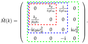
Here, the red, blue, and green boxes in Equation (13) correspond to the cases of linear dispersion, Drude dispersion, and Lorentz dispersion, respectively, without considering loss. Therefore, they possess two, three, and four eigenmodes, respectively. This matrix can be further extended when more Lorentz oscillators are considered, where each additional oscillator introduces two components, and , and yields a pair of positive- and negative-frequency modes.
Note that due to the non-Hermiticity of , the eigenstates are not orthonormal under the standard inner product. We define a metric to further refine the projection of the modes. It can be expressed via the inner product of : Consequently, we obtain the dual basis as where are the elements of the inverse metric, satisfying . Thus, the original and dual bases satisfy . The temporal evolution of any given state is determined by its initial state. Here, is the expand associated with . Following a parameter jump, the field quantities are scaled according to the different continuity conditions as aforementioned, and can thus be described by a transformation operator: Here, represents the scaling factor for the field labeled by i (e.g., for the electric field). Hence, after the temporal parameter jump (from parameter 1 to parameter 2), the state can be expressed in the new basis as
The coefficients for state transitions are thus expressed as Taking the simplest case of background permittivity modulation in dispersionless medium as an example, when the permittivity jumps from to , the electric field transmittance and reflectance can be expressed as follows:
where, by normalizing the basis vectors to a unit electric-field component, we obtain the scattering coefficients for the electric field. Under the conventional continuity conditions, Equation (15) recovers the familiar temporal reflection and transmission coefficients widely used in time-varying electromagnetics [7,44]. In the cases of continuity of the electric displacement field, , whereas in the cases of continuity of electric field, . It is observed that persists in this scenario. In fact, adopting a mixed continuity condition between them enables us to choose the scaling factor to eliminate time reflection.
However, although setting eliminates temporal reflection, the case leads to . This is exactly the case of , which represents an adiabatic modulation. This indicates that under periodic modulation of permittivity, the traveling wave fails to achieve net amplification. This limitation, however, can be overcome by introducing modulation of the permeability . In theoretical studies of time-varying photonics, it is common to consider permeability as a modulatable parameter [45,46,47,48]. The circuit model in Figure 2, in which a time-varying inductance represents an effective , provides one possible implementation in dynamic transmission lines or time-varying electromagnetic metasurfaces, etc. The corresponding transmission and reflection coefficients for the electric field can be expressed as
With , it follows that , and thus . The condition for this product to be greater than unity requires . The subscripts on and denote quantities associated with a change from medium 1 to 2, and vice versa. Hence, we continue to assume tunability of the scaling factors. Specifically, we constrain the electric-field scaling factor to fall between the continuity of and that of , and the magnetic-field scaling factor between the continuity of and that of magnetic flux density . We further assume that and , which leads to the following constraints , , , and .
By further assuming that , we can obtain the condition for maximizing : Thus, we finally arrive at the maximum transmission coefficient over one modulation cycle:
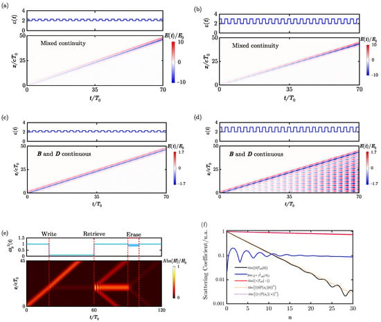
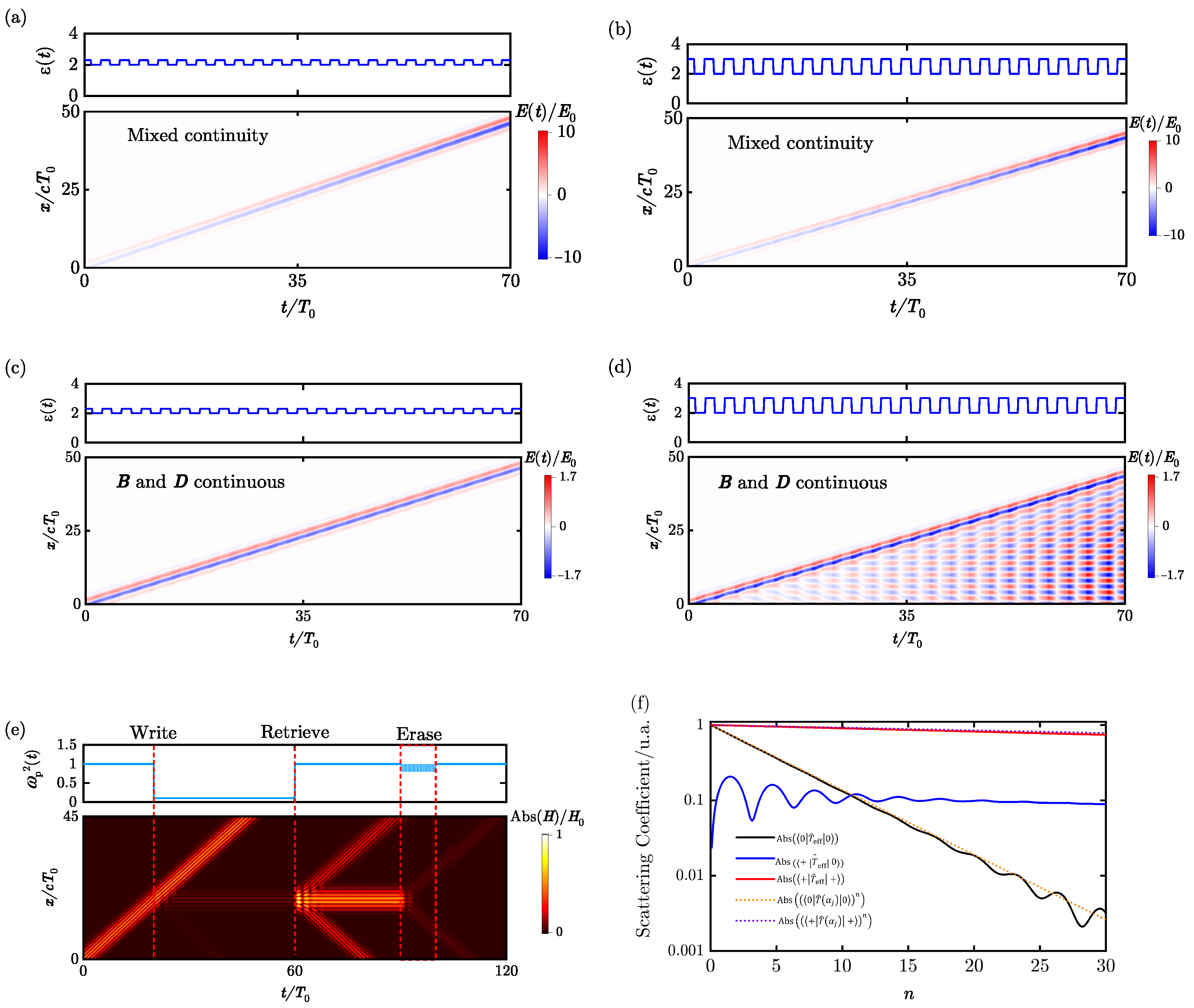
Under the reflectionless condition, the net amplification per cycle is set by the smaller of the two modulation depths, which in our example is ; increasing the permittivity modulation depth alone cannot further increase the gain. In Figure 4, we compute the spatiotemporal evolution of the electric field under simultaneous modulation of permittivity and permeability. The calculation is performed by directly solving the one-dimensional Maxwell equations using the finite-difference time-domain method (FDTD) [41]. For the Drude case, the polarization current is evolved together with Maxwell’s equations using the auxiliary differential-equation formulation [49]. At each temporal interface, the field state is transformed according to the scaling operator . The computational domain was chosen to be sufficiently large such that the wave did not reach the spatial boundaries within the observation time. The source has a Gaussian profile, and the modulation frequency is chosen to be twice the central frequency of the source (). In Figure 4a,c, we set , , , and . Figure 4a adopts the hybrid boundary condition, whereas Figure 4c assumes the continuity of D and B. It can be seen that Figure 4a exhibits reflectionless amplification of traveling waves. In Figure 4c, the conventional continuity condition produces only an extremely narrow momentum gap with a correspondingly small growth rate. Since only a very small spectral component of the finite-bandwidth pulse falls within the gain region, its initial energy is much smaller than the total pulse energy and cannot accumulate to a comparable level within the plotted time interval. In Figure 4b,d, the permittivity modulation amplitude is increased by setting . The hybrid condition is applied in Figure 4b, whereas Figure 4d shares the same continuity condition as Figure 4c. The field-scaling factors and corresponding temporal scattering coefficients are summarized in Supplementary Materials. Figure 4b shows reflectionless amplification of traveling waves with a growth rate identical to that in Figure 4a. This confirms that the amplification rate of traveling waves depends only on the ratio . For Figure 4d, the larger modulation amplitude gives rise to a broadened momentum band gap with higher growth rate. A larger fraction of the incident pulse spectrum is consequently amplified, leading to a significant standing-wave accumulation. By contrast, under the cases in Figure 4a,b, increasing the larger permittivity-modulation depth does not change the amplification rate, which remains limited by the smaller permeability-modulation depth. The amplification mechanism enabled by the hybrid continuity condition is therefore non-resonant, broadband, and reflectionless, fundamentally distinct from that in photonic time crystals, thus greatly expanding the potential of temporal modulation for signal amplification. Conversely, the time-reversed counterpart of this process enables reflectionless wave absorption.
Figure 4.
Simulations showing pulse spatiotemporal evolution under different continuity conditions. (a–d) Spatiotemporal evolution of the electric field under simultaneous modulation of permittivity and permeability . In all cases, and . (a,c) correspond to and ; (b,d) correspond to increased permittivity modulation with and . Mixed continuity conditions are applied in (a,b), while (c,d) assume continuity of and . (e) Pulse storage and retrieval enabled by temporal modulation of the plasma frequency. (f) Evolution of the matrix elements describing the scattering process with the number of modulation cycles.
In Drude media, the mixed continuity condition can also lift the limitations in temporal modulation. We label the three eigenstates in medium i corresponding to , , and as , , and , respectively. The non-orthogonality of the eigenmodes leads to a non-reciprocal relation between the inner products It is well known that, in Drude media, a temporal parameter jump can convert traveling waves into static magnetic fields [7], as evidenced by the nonzero coefficient. is nonzero. However, under plasma frequency modulation, the zero-frequency (DC) mode remains independent of the dielectric parameters, namely Consequently, This suggests that the conversion from static magnetic fields to propagating waves is prohibited under current continuity conditions. This prohibition of mode conversion is analogous to a selection rule. Fortunately, this limitation can be overcome by modifying the condition of current continuity, i.e., making nonzero. Specifically, the coefficients for the conversion from oscillatory to static fields and vice versa can be written as follows:
and
where the basis vectors are normalized to a unit current density component. It is evident that the conversion from oscillatory to static fields is prohibited when is continuous, i.e., . This conversion thus provides a mechanism for optical pulse storage, with potential applications in optical computing.
We now provide a detailed description of this scheme. The spatiotemporal evolution of the pulse is presented in Figure 4e. Here, the initial plasma frequency is set to unity (), and a Gaussian pulse with a center frequency of is adopted to minimize dispersive effects. The writing process involves a decrease in plasma density to , with current density kept continuous. The retrieval process, as illustrated in Figure 4e, restores the plasma frequency to its initial value while keeping conserved, i.e., . By comparing Equations (17) and (18), it can be seen that the retrieval process, in fact, acts as a spatial operator whose transfer function is governed by the equation . This process physically manifests as a second-order integral in the large-k regime and a second-order derivative in the small-k regime, offering a native, reconfigurable interface for analog photonic computing that performs either integration or differentiation. In principle, pulse storage introduces no information loss. In practice, the limited bandwidth and the scaling operation attenuate the high spatial frequency components and degrade the signal-to-noise ratio. To erase the signal, we employ a multi-cycle, high-frequency modulation of the plasma density, described by the following equation:
where characterizes the equivalent scattering process. n is the number of modulation cycles. Under the assumption , the modulation scheme involves periodic alternation between and , with each state lasting for a duration . For the downward transition (corresponding to a decrease in plasma density), we set , where . For the reverse transition (increase in plasma density), the current is taken to be continuous, so that the transfer matrix is the identity transformation.
Further, since is diagonalizable, there exists an invertible matrix P such that , where is the diagonal matrix with the corresponding eigenvalues on its diagonal. Then, we have
When the modulation frequency is high (i.e.,) and the modulation amplitude is small (), the diagonal elements of P approach unity, and the eigenvalues can be approximated by . Figure 4f shows these matrix elements as functions of the cycle number n, comparing the exact results (solid lines) with the analytical approximation (dotted lines). This comparison demonstrates that the approximation successfully captures the amplitude dynamics of the modes.
Specifically, for large values of , the decay of static fields is much faster than the propagating wave (see Supplementary Materials). This verifies that, even far away from the momentum band gap, mode separation still occurs under such mixed continuity conditions as described above, enabling mode selection. As shown in Figure 4e, after the periodic modulation described above, the static field decays exponentially and is thus erased.
4. Conclusions and Discussion
In conclusion, this work has developed a comprehensive framework for time-varying dispersive media by considering different field continuity conditions, thereby introducing a new degree of freedom that alters the system’s response. We have shown that this additional freedom enables phenomena previously thought impossible under pure temporal modulation. The present study demonstrates the phenomenon of broadband, reflectionless amplification of traveling waves. This phenomenon is distinct from that exhibited by photonic time crystals, which rely on momentum bandgaps. Furthermore, we achieve controlled conversion between static and propagating fields, a functionality with direct implications for optical pulse storage and processing. Both effects are shown to be unattainable under conventional single-continuity conditions with purely temporal modulation.
The theoretical framework established in this work complements research on the Floquet physics of photonic time crystals [14,23,41] and studies deriving temporal continuity conditions based on microscopic modulation mechanisms [7,26]. This framework does not attempt to specify universal continuity conditions for a particular material. Instead, the relations among the field variables imposed by a specific modulation process are represented by polytropic indices or a state-transformation operator and are used as macroscopic inputs for determining the electromagnetic-field evolution. With identical macroscopic parameter evolution and initial conditions, modulation processes with different microscopic dynamics but corresponding to the same set of polytropic indices or the same transformation operator produce the same macroscopic electromagnetic response. Temporal modulation processes may therefore be classified according to their induced continuity transformations. Correspondingly, one can inverse-design the procedure for the required polytropic indices or transformation operators starting from the target electromagnetic modal transformation and then further identify the physical modulation mechanisms capable of realizing those continuity conditions.
The circuit model presented in this work provides a concrete example of this design procedure. Elementary charge-conserving and voltage-conserving circuit operations can be selected and combined to realize a range of continuity transformations, providing a possible implementation in dynamic transmission lines and time-varying electromagnetic metasurfaces. When a modulation process contains several successive continuity transformations, the corresponding evolution generators or finite transformation operators do not generally commute. Consequently, even if the initial and final material parameters are identical, the system’s electromagnetic response may still depend on the specific modulation path and the sequence in which the parameters change. This path dependence offers a potential direction for expanding the control capabilities of time-varying systems. More broadly, the framework may provide a basis for future applications in on-chip amplification, optical computing, and communications.
Supplementary Materials
The following supporting information can be downloaded at: https://www.mdpi.com/article/10.3390/photonics13080699/s1, Figure S1: Time evolution of an LC circuit with modulated capacitance for ; Figure S2: Time evolution of an LC circuit with modulated capacitance for ; Figure S3: Time evolution of an LC circuit with modulated capacitance for ; Figure S4: Time evolution of an LC circuit with modulated capacitance under asymmetric continuity conditions; Figure S5: Band structures of three different dispersion types and the corresponding phase relations of the fields; Figure S6: Band structure under permittivity modulation; Figure S7: Band diagrams for the Lorentz dispersive system under plasma-frequency modulation with different resonance frequencies; Figure S8: Fourier spectrum of the normalized modulation-induced coefficient; Table S1: Scaling factors and the corresponding electric-field scattering coefficients in Figure 4a–d.
Author Contributions
Conceptualization, Y.W. (Yongge Wang), J.Y., C.Y. and Z.Z.; methodology, Y.W. (Yongge Wang) and J.Y.; formal analysis, Y.W. (Yongge Wang), Y.W. (Ying Wang) and J.Y.; investigation, Y.W. (Yongge Wang) and Y.W. (Ying Wang); writing—original draft preparation, Y.W. (Yongge Wang); writing—review and editing, J.Y., C.Y. and Z.Z.; supervision, J.Y., C.Y. and Z.Z.; funding acquisition, J.Y., C.Y. and Z.Z. All authors have read and agreed to the published version of the manuscript.
Funding
This research was funded by the National Natural Science Foundation of China (NSFC, grant numbers 12575213, 12505229 and U2541210), the Natural Science Foundation of Heilongjiang Province of China (grant number YQ2024A008), the China Radio Wave Propagation Research Institute Stable Support for Scientific Research Funding (project number A251200020), and the National Key R & D Program of China (grant number 2025YFF0512000).
Institutional Review Board Statement
Not applicable.
Informed Consent Statement
Not applicable.
Data Availability Statement
The data supporting the findings of this study are available from the corresponding authors upon reasonable request.
Conflicts of Interest
The authors declare no conflicts of interest.
References
- Li, H.; Yin, S.; He, H.; Xu, J.; Alù, A.; Shapiro, B. Stationary charge radiation in anisotropic photonic time crystals. Phys. Rev. Lett. 2023, 130, 093803. [Google Scholar] [CrossRef] [Scilit] [PubMed]
- Li, H.; Yin, S.; Alù, A. Nonreciprocity and Faraday Rotation at Time Interfaces. Phys. Rev. Lett. 2022, 128, 173901. [Google Scholar] [CrossRef] [Scilit] [PubMed]
- He, H.; Zhang, S.; Qi, J.; Bo, F.; Li, H. Faraday rotation in nonreciprocal photonic time-crystals. Appl. Phys. Lett. 2023, 122, 051703. [Google Scholar] [CrossRef] [Scilit]
- Galiffi, E.; Wang, Y.T.; Lim, Z.; Pendry, J.B.; Alù, A.; Huidobro, P.A. Wood Anomalies and Surface-Wave Excitation with a Time Grating. Phys. Rev. Lett. 2020, 125, 127403. [Google Scholar] [CrossRef] [Scilit] [PubMed]
- Dikopoltsev, A.; Sharabi, Y.; Lyubarov, M.; Lumer, Y.; Tsesses, S.; Lustig, E.; Kaminer, I.; Segev, M. Light emission by free electrons in photonic time-crystals. Proc. Natl. Acad. Sci. USA 2022, 119, e2119705119. [Google Scholar] [CrossRef] [Scilit] [PubMed]
- Bar-Hillel, L.; Dikopoltsev, A.; Kam, A.; Sharabi, Y.; Segal, O.; Lustig, E.; Segev, M. Time Refraction and Time Reflection above Critical Angle for Total Internal Reflection. Phys. Rev. Lett. 2024, 132, 263802. [Google Scholar] [CrossRef] [Scilit] [PubMed]
- Galiffi, E.; Solis, D.M.; Yin, S.; Engheta, N.; Alu, A. Electrodynamics of photonic temporal interfaces. Light-Sci. Appl. 2025, 14, 338. [Google Scholar] [CrossRef] [Scilit] [PubMed]
- Wang, S.; Shao, N.; Chen, H.; Chen, J.; Qian, H.; Wu, Q.; Duan, H.; Alu, A.; Huang, G. Experimental realization of temporal refraction and reflection in elastic beams. Nat. Commun. 2025, 16, 9520. [Google Scholar] [CrossRef] [Scilit] [PubMed]
- Jones, T.R.; Kildishev, A.V.; Segev, M.; Peroulis, D. Time-reflection of microwaves by a fast optically-controlled time-boundary. Nat. Commun. 2024, 15, 6786. [Google Scholar] [CrossRef] [Scilit] [PubMed]
- Rizza, C.; Vincenti, M.A.; Castaldi, G.; Contestabile, A.; Galdi, V.; Scalora, M. Harnessing the Natural Resonances of Time-Varying Dispersive Interfaces. Phys. Rev. Lett. 2024, 133, 186902. [Google Scholar] [CrossRef] [Scilit] [PubMed]
- Zhou, Y.; Alam, M.Z.; Karimi, M.; Upham, J.; Reshef, O.; Liu, C.; Willner, A.E.; Boyd, R.W. Broadband frequency translation through time refraction in an epsilon-near-zero material. Nat. Commun. 2020, 11, 2180. [Google Scholar] [CrossRef] [Scilit] [PubMed]
- Qin, C.; Ye, H.; Wang, S.; Zhao, L.; Liu, M.; Li, Y.; Hu, X.; Liu, C.; Wang, B.; Longhi, S.; et al. Observation of discrete-light temporal refraction by moving potentials with broken Galilean invariance. Nat. Commun. 2024, 15, 5444. [Google Scholar] [CrossRef] [Scilit] [PubMed]
- He, Y.; Dong, Z.; Li, G.; Yu, P.; Wu, X.; Chen, X.; Yuan, L. Observing momentum conservation at temporal interfaces in synthetic frequency dimension. Sci. Adv. 2025, 11, eadz5445. [Google Scholar] [CrossRef] [Scilit] [PubMed]
- Sharabi, Y.; Lustig, E.; Segev, M. Disordered Photonic Time Crystals. Phys. Rev. Lett. 2021, 126, 163902. [Google Scholar] [CrossRef] [Scilit] [PubMed]
- Apffel, B.; Wildeman, S.; Eddi, A.; Fort, E. Experimental Implementation of Wave Propagation in Disordered Time-Varying Media. Phys. Rev. Lett. 2022, 128, 094503. [Google Scholar] [CrossRef] [Scilit] [PubMed]
- Lyubarov, M.; Lumer, Y.; Dikopoltsev, A.; Lustig, E.; Sharabi, Y.; Segev, M. Amplified emission and lasing in photonic time crystals. Science 2022, 377, 425–428. [Google Scholar] [CrossRef] [Scilit] [PubMed]
- Zurita-Sánchez, J.R.; Halevi, P.; Cervantes-González, J.C. Reflection and transmission of a wave incident on a slab with a time-periodic dielectric function ε(t). Phys. Rev. A 2009, 79, 053821. [Google Scholar] [CrossRef] [Scilit]
- Lustig, E.; Sharabi, Y.; Segev, M. Topological aspects of photonic time crystals. Optica 2018, 5, 1390–1395. [Google Scholar] [CrossRef] [Scilit]
- Sharabi, Y.; Dikopoltsev, A.; Lustig, E.; Lumer, Y.; Segev, M. Spatiotemporal photonic crystals. Optica 2022, 9, 585–592. [Google Scholar] [CrossRef] [Scilit]
- Reyes-Ayona, J.R.; Halevi, P. Observation of genuine wave vector (k or β) gap in a dynamic transmission line and temporal photonic crystals. Appl. Phys. Lett. 2015, 107, 074101. [Google Scholar] [CrossRef] [Scilit]
- Wang, X.; Mirmoosa, M.S.; Asadchy, V.S.; Rockstuhl, C.; Fan, S.; Tretyakov, S.A. Metasurface-based realization of photonic time crystals. Sci. Adv. 2023, 9, eadg7541. [Google Scholar] [CrossRef] [Scilit] [PubMed]
- Sheinfux, H.H.; Lumer, Y.; Ankonina, G.; Genack, A.Z.; Bartal, G.; Segev, M. Observation of Anderson localization in disordered nanophotonic structures. Science 2017, 356, 953–956. [Google Scholar] [CrossRef] [Scilit] [PubMed]
- Mirmoosa, M.S.; Koutserimpas, T.; Ptitcyn, G.; Tretyakov, S.; Fleury, R. Dipole polarizability of time-varying particles. New J. Phys. 2022, 24, 063004. [Google Scholar] [CrossRef] [Scilit]
- Solís, D.M.; Engheta, N. Functional analysis of the polarization response in linear time-varying media: A generalization of the Kramers-Kronig relations. Phys. Rev. B 2021, 103, 144303. [Google Scholar] [CrossRef] [Scilit]
- Feinberg, J.; Fernandes, D.E.; Shapiro, B.; Silveirinha, M.G. Plasmonic Time Crystals. Phys. Rev. Lett. 2025, 134, 183801. [Google Scholar] [CrossRef] [Scilit] [PubMed]
- Wang, Y.; Yao, J.; Wang, Y.; Yuan, C.; Zhou, Z. How does loss act on electromagnetic wave propagation in time-varying plasmas? Opt. Contin. 2026, 5, 1944–1959. [Google Scholar] [CrossRef] [Scilit]
- Galiffi, E.; Yin, S.; Alú, A. Tapered photonic switching. Nanophotonics 2022, 11, 3575–3581. [Google Scholar] [CrossRef] [Scilit] [PubMed]
- Newton, I. Philosophiae Naturalis Principia Mathematica; G. Brookman: Glasguae, UK, 1833; Volume 1. [Google Scholar]
- Whiteside, H. Newton’s Derivation of the Velocity of Sound. Am. J. Phys. 1964, 32, 384. [Google Scholar] [CrossRef] [Scilit]
- Laplace, P.d. Sur la vitesse du son dans l’air et dans l’eau. Ann. Chim. Phys. 1816, 3, 238–241. [Google Scholar]
- Pierce, A.D. Acoustics: An Introduction to Its Physical Principles and Applications; Springer: Cham, Switzerland, 2019. [Google Scholar]
- Lighthill, M.J.; Lighthill, J. Waves in Fluids; Cambridge University Press: Cambridge, UK, 2001. [Google Scholar]
- Bakunov, M.; Shirokova, A.; Kurnikov, M.; Maslov, A. Electromagnetic waves in a Lorentzian medium with periodically modulated oscillator density. Phys. Rev. A 2024, 110, 063532. [Google Scholar] [CrossRef] [Scilit]
- Un, I.W.; Sarkar, S.; Sivan, Y. Electronic-based model of the optical nonlinearity of low-electron-density Drude materials. Phys. Rev. Appl. 2023, 19, 044043. [Google Scholar] [CrossRef] [Scilit]
- Khurgin, J.B. Energy and power requirements for alteration of the refractive index. Laser Photonics Rev. 2024, 18, 2300836. [Google Scholar] [CrossRef] [Scilit]
- Maslov, A. Wave transformation in transmission lines with rapid connection and disconnection of reactive elements. J. Appl. Phys. 2025, 137, 014503. [Google Scholar] [CrossRef] [Scilit]
- Xiong, J.; Zhang, X.; Duan, L.; Wang, J.; Long, Y.; Hou, H.; Yu, L.; Zou, L.; Zhang, B. Observation of wave amplification and temporal topological state in a non-synthetic photonic time crystal. Nat. Commun. 2025, 16, 11182. [Google Scholar] [CrossRef] [Scilit] [PubMed]
- Hou, H.; Peng, K.; Wang, Y.; Wang, J.; Zhang, X.; Wang, R.; Hu, H.; Xiong, J. Experimental realization of a full-band wave antireflection based on temporal taper metamaterials. Commun. Phys. 2026, 9, 64. [Google Scholar] [CrossRef] [Scilit]
- Ye, X.; Wang, Y.G.; Yao, J.F.; Wang, Y.; Yuan, C.X.; Zhou, Z.X. Realization of spatiotemporal photonic crystals based on active metasurface. Laser Photonics Rev. 2025, 19, 2401345. [Google Scholar] [CrossRef] [Scilit]
- Ai, H.; Chen, K.; Wang, X.; Zhao, J.; Jiang, T.; Feng, Y. Scattering of electromagnetic waves in time-varying media with finite switching duration. Phys. Rev. B 2026, 113, 195301. [Google Scholar] [CrossRef] [Scilit]
- Ye, X.; Wang, Y.; Yao, J.; Wang, Y.; Yuan, C.; Zhou, Z. Floquet modeling of surface-wave amplification in two-dimensional photonic time crystals. Phys. Rev. B 2024, 109, 165304. [Google Scholar] [CrossRef] [Scilit]
- Roy, R.; Harper, F. Periodic table for Floquet topological insulators. Phys. Rev. B 2017, 96, 155118. [Google Scholar] [CrossRef] [Scilit]
- Pan, Y.; Chen, Z.; Wang, B.; Poem, E. Floquet Gauge Anomaly Inflow and Arbitrary Fractional Charge in Periodically Driven Topological-Normal Insulator Heterostructures. Phys. Rev. Lett. 2023, 130, 223403. [Google Scholar] [CrossRef] [Scilit] [PubMed]
- Mendonça, J.T.; Shukla, P.K. Time Refraction and Time Reflection: Two Basic Concepts. Phys. Scr. 2002, 65, 160. [Google Scholar] [CrossRef] [Scilit]
- Martínez-Romero, J.S.; Becerra-Fuentes, O.M.; Halevi, P. Temporal photonic crystals with modulations of both permittivity and permeability. Phys. Rev. A 2016, 93, 063813. [Google Scholar] [CrossRef] [Scilit]
- Martínez-Romero, J.S.; Halevi, P. Parametric resonances in a temporal photonic crystal slab. Phys. Rev. A 2018, 98, 053852. [Google Scholar] [CrossRef] [Scilit]
- Gaxiola-Luna, J.G.; Halevi, P. Temporal photonic (time) crystal with a square profile of both permittivity ε(t) and permeability μ(t). Phys. Rev. B 2021, 103, 144306. [Google Scholar] [CrossRef] [Scilit]
- Shaposhnikov, L.; Barredo-Alamilla, E.; Wilczek, F.; Gorlach, M.A. Probing Ultrafast Magnetization Dynamics via Synthetic Axion Fields. Phys. Rev. Lett. 2025, 134, 246702. [Google Scholar] [CrossRef] [Scilit] [PubMed]
- Ye, X.; Wang, Y.; Yao, J.; Wang, Y.; Yuan, C.; Zhou, Z. Structure-independent flat bands induced by discontinuity plasma-air interface in photonic crystals. Phys. Rev. B 2023, 107, 195301. [Google Scholar] [CrossRef] [Scilit]
Disclaimer/Publisher’s Note: The statements, opinions and data contained in all publications are solely those of the individual author(s) and contributor(s) and not of MDPI and/or the editor(s). MDPI and/or the editor(s) disclaim responsibility for any injury to people or property resulting from any ideas, methods, instructions or products referred to in the content. |
© 2026 by the authors. Licensee MDPI, Basel, Switzerland. This article is an open access article distributed under the terms and conditions of the Creative Commons Attribution (CC BY) license.