


Abstract
We propose a novel silicon-based THz Mach–Zehnder interferometer (MZI) biosensor integrated with a polarization splitter and rotator (PSR). An optimized PSR is positioned at the input of the MZI, enabling arbitrary polarization inputs to be converted into the same TE mode, which eliminates the dependence of conventional MZI sensors on the input light polarization. The PSR structural parameters are optimized using 3D-FDTD simulations to achieve phase matching, and the calculation results show that efficient TM–TE-polarization conversion occurs along a coupling length of 22.9 mm. Furthermore, the PSR achieves a maximum TE-mode extinction ratio of −30.1 dB and a polarization conversion efficiency of 82.33% in the 0.44 to 0.45 THz range, effectively maintaining the polarization consistency of light entering the MZI. Meanwhile, the characteristic frequency shows a regular blue shift with increasing external refractive index, and the final results demonstrate that the designed MZI biosensor achieves a high sensitivity of 13,215.81 nm/RIU near the center frequency of 0.45 THz. All results presented in this work are obtained through numerical simulations, and experimental validation as well as analyte-concentration-dependent refractive index characterization will be addressed in future studies. To sum up, we propose a high-sensitivity terahertz MZI biosensor featuring a PSR with an on-chip integration scheme, which supports arbitrary polarization inputs and offers a highly integrated solution for specific detection in biomedicine.
1. Introduction
Terahertz (THz) technology has attracted growing interest in recent years. With continuous progress in terahertz sources, detectors, and system integration, terahertz technology is rapidly evolving from laboratory-scale spectroscopy toward compact, integrated, and application-oriented platforms [1,2]. To meet the growing demand for miniaturized and high-performance terahertz devices, integrated photonic chips have emerged as a promising platform. Integrated photonic chips have attracted considerable attention in modern sensing and communication applications due to their compact footprint, high sensitivity, and potential for low-cost, large-scale fabrication [3,4,5,6,7,8]. In polarization-multiplexed and optical communication systems, polarization beam splitters (PBSs) and polarization beam rotators (PBRs) serve as essential polarization management components. A PBS separates two orthogonally polarized optical modes and directs them to different output ports, whereas a PBR converts orthogonal polarizations into a common polarization state. Various types of passive polarization splitters and polarization rotators have been reported in recent years [7,8,9,10,11]. Among them, the polarization splitter and rotator [12,13,14]—which integrates both polarization splitting and rotation functionalities—can simultaneously perform these two operations, thereby substantially reducing the complexity and footprint of silicon-based integrated photonic circuits. Wang et al. [15] designed a compact polarization rotator based on asymmetric Si nanowires with an etched corner, which realized a 22.1 μm conversion length, nearly 100% polarization conversion efficiency at 1550 nm and over 97% PCE across a 120 nm bandwidth. Xiong et al. [16] presented a fabrication-tolerant broadband PSR composed of a silicon wire waveguide coupled to a taper-etched waveguide, this device featured −0.09 dB TM-to-TE conversion loss in the C-band; Bai et al. [17] proposed an ultra-short plasmonic PSR based on an asymmetric bent directional coupler, where the bent structure and plasmonic effect induced large birefringence, enabling a record 5.21 μm coupling length, over 99.9% PCE at 1.55 μm.
The Mach–Zehnder interferometer [18,19,20] is a well-established optical sensing architecture that detects environmental variations by monitoring shifts in its interference spectrum. Owing to its high sensitivity, the MZI has been widely employed in biomedical imaging and tissue diagnostics, such as reconstructing the microscopic structure of muscles and tendons to evaluate injury sites and rehabilitation progress [21,22,23]. However, interferometric sensors require input optical fields with identical polarization states; otherwise, phase modulation precision and interference contrast are degraded, resulting in distorted or unstable output signals. In this context, the PSR effectively unifies arbitrary input polarizations into a single state, ensuring high-quality interference and consistent array performance. El Shamy et al. [24] proposed a mid-infrared integrated MZI gas sensor using suspended silicon waveguide, which exhibited a high wavelength sensitivity of 7028 nm/RIU at the wavelength of 5 μm. Ma et al. [25] proposed a cost-effective liquid refractive index sensor in polymer materials by employing a MZI formed with the conventional strip waveguide, which achieved an ultra-high RI sensitivity of 9 × 10⁴ nm/RIU with a reference arm length of 7980.0 μm. Doughan et al. [26] presented a strip-loaded MZI for absolute refractive index sensing, which adopted a novel approach of large opening in the sensing region and used the analyte as the loading strip to realize high-sensitivity detection.
In this work, we present an on-chip interferometric sensor that integrates a PSR with a MZI. Specifically, the PSR is incorporated at the input stage of the MZI to uniformly convert arbitrary input polarizations into the transverse electric (TE) mode. By doing so, the system effectively eliminates polarization-dependent loss and phase errors, which in turn enhances interference fringe contrast and improves overall sensing efficiency. Consequently, the proposed configuration achieves polarization-independent and highly stable on-chip interferometric sensing system. Owing to its compact footprint and robust polarization performance, the device offers a promising platform for reliable, high-precision biomedical sensing applications.
2. Principle and Structure
2.1. Principle of the PSR
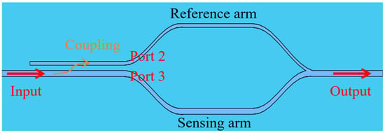
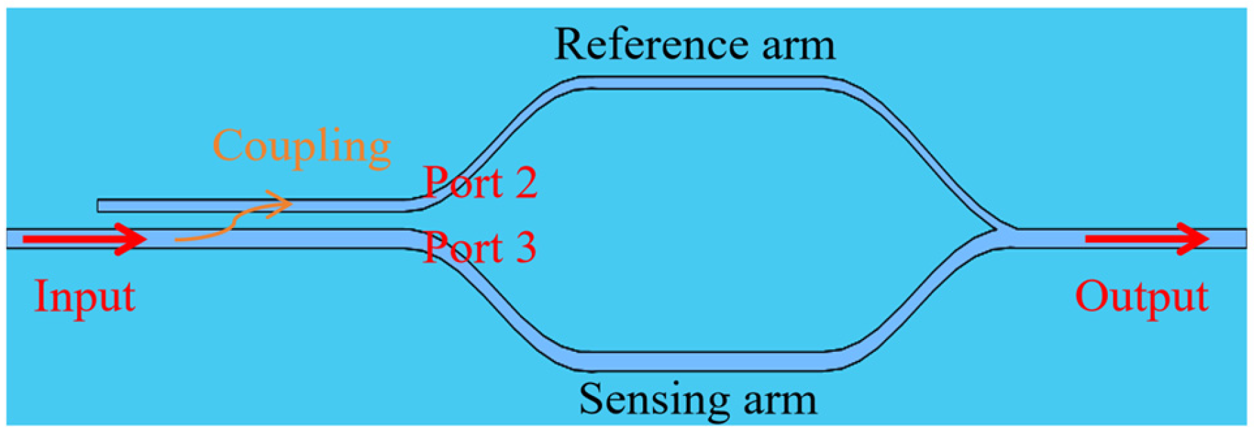
Figure 1 shows the structure of the MZI sensor integrated with a PSR based on an asymmetric dual-waveguide directional coupler. Figure 2 illustrates the sensing operation process. The PSR consists of three parts: (1) input waveguide, (2) coupling waveguide, and (3) output bent waveguide. The output bent waveguide has two output ports, referred to as Port 2 and Port 3. The core operating mechanism of the PSR is based on the mode effective refractive index matching principle, which can be expressed as Equation (1):
where denotes the effective index of the TM0 polarization mode in the input waveguide, and represents the effective index of the TE-polarization mode in the coupling waveguide. When the effective index of the TM mode in the input waveguide equals that of the TE mode in the coupling waveguide, the TM mode in the input waveguide couples into the coupling waveguide and is simultaneously converted into the TE mode, which is finally output from Port 2 of the output bent waveguide. Meanwhile, the TE mode in the input waveguide does not satisfy the phase-matching condition; therefore, the TE mode remains confined within the input waveguide with negligible inter-waveguide coupling and eventually exits from Port 3 of the output bent waveguide. Through this mechanism, the polarization splitting and rotation functionality is effectively achieved.
Figure 1.
The structure of the MZI sensor integrated with a PSR.
Figure 2.
The sensing operation process based on the MZI sensor integrated with a PSR.
In the polarization splitter and rotator based on an asymmetric dual-waveguide directional coupler, there exists a set of even and odd modes with effective refractive indices denoted as neven and nodd, respectively. The phase difference between the even and odd supermodes determines the periodic power exchange along the coupling region. This mechanism provides the physical basis for efficient mode coupling and TM–TE-polarization conversion in the proposed PSR structure.
When the input TM mode propagates over a certain length at the operating wavelength, it can be completely coupled into the adjacent waveguide. This length is defined as the coupling length Lc. Lc is a critical parameter that determines the overall size of the device and is governed by the effective refractive index difference between the odd and even modes, as expressed in Equation (2):
2.2. Principle of the Achilles Tendon Cell Density Sensor Based on MZI
The 3D structure of the MZI sensor is shown in Figure 2. In this study, the MZI sensor is employed to detect variations in refractive index corresponding to different Achilles tendon cell densities. The reference arm and sensing arm of the MZI sensor correspond to the two output waveguides of the preceding PSR. Arbitrary input polarization states enter the MZI sensor through the PSR input waveguide, where they are converted by the PSR into two beams with identical TE-polarization modes and directed into the two arms of the MZI. The sensing arm waveguide is in direct contact with the sample under test, allowing the evanescent field to penetrate into the sample. The evanescent field, carrying information about the sample’s refractive index, then returns to the waveguide to continue propagation, enabling the detection of subtle changes in the sample’s refractive index.
Due to the large distance between the reference arm and the sensing arm, the light beams can propagate independently in the two arms of the MZI sensor. When the fields in the two arms recombine at the output, distinct interference fringes are generated. The output intensity is expressed as in Equation (3):
where is the output light intensity, and are the light intensity of the sensing arm and the reference arm of the MZI sensor, respectively, and the phase difference between the two arms is denoted by . When the external biological environment of the sensing arm changes, the effective refractive index of the guided mode in the sensing arm will be affected, thus affecting the phase difference between the two arms. The phase difference with sensing information can be expressed as:
Here, denotes the effective index of the TE mode in the sensing arm, denotes the effective index of the TE mode in the reference arm, and represents the variation in the effective index of the TE mode in the sensing arm induced by changes in the external biological environment. The change in the external biological environment can be converted into the offset of the interference spectrum, and the information of the external biological environment can be obtained by demodulating the change in the characteristic frequency in the interference spectrum.
2.3. Structure and Parameters
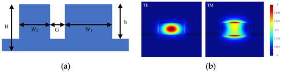
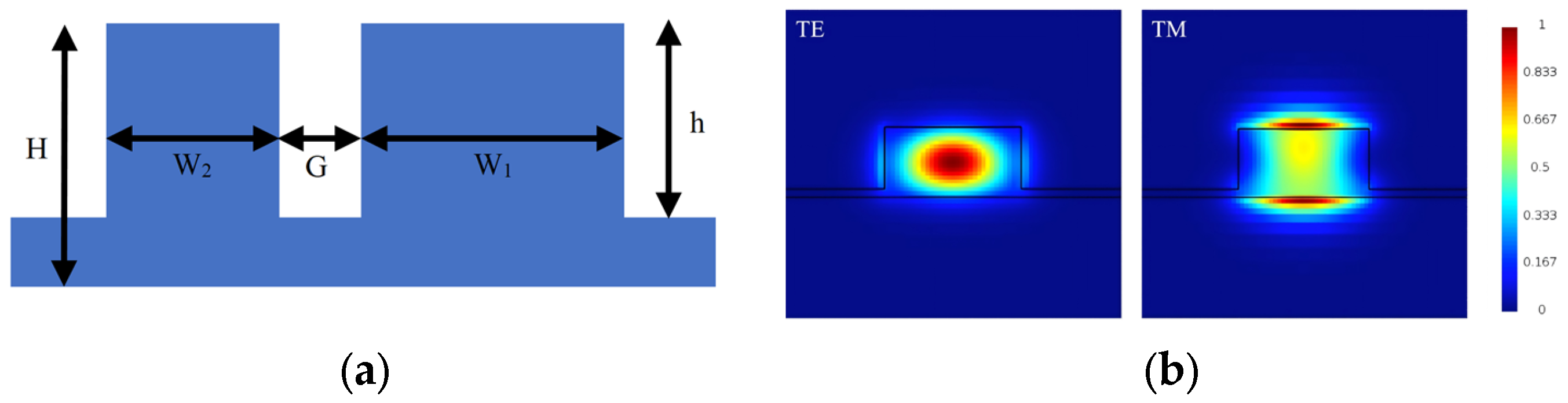
Figure 3a shows the cross section of the PSR coupling region along with the definitions of its structural parameters. The device is designed using high-resistance silicon with a thickness of H = 130 μm and a ridge waveguide height of h = 115 μm. To satisfy the phase-matching condition, the waveguide widths are determined through calculation such that the effective index of the quasi-TM mode in the input waveguide equals that of the quasi-TE mode in the coupling waveguide, while the effective index of the TE mode in the input waveguide is much larger than that of the quasi-TE mode in the coupling waveguide. When the above conditions are met, the TE-polarization mode transmitted in the input waveguide will be directly transmitted along the input waveguide to the output waveguide, whereas the TM polarization mode in the input waveguide will be coupled to the polarization mode of the coupling waveguide.
Figure 3.
The coupling area. (a) The cross section view and its structural parameters. (b) The THz field distributions of TE and TM polarization mode in the input waveguide at 0.45 THz.
The proposed device is designed on a 2-inch double-side polished high-resistivity silicon substrate with a thickness ranging from 130 to 200 μm, which is suitable for low-loss terahertz wave propagation. The corresponding fabrication process may include substrate cleaning, photoresist spin-coating, ultraviolet lithography, development, deep reactive ion etching (DRIE) for waveguide pattern definition, photoresist removal, and wafer dicing.
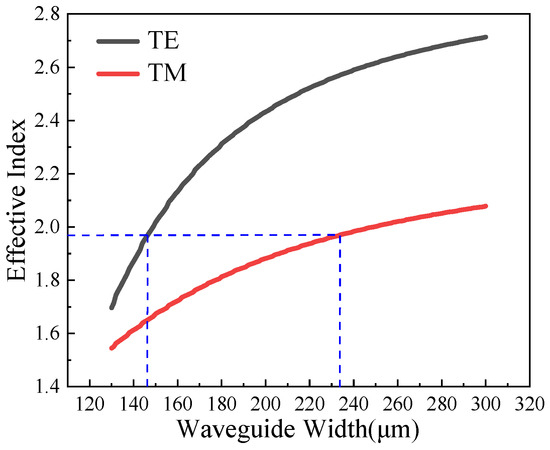
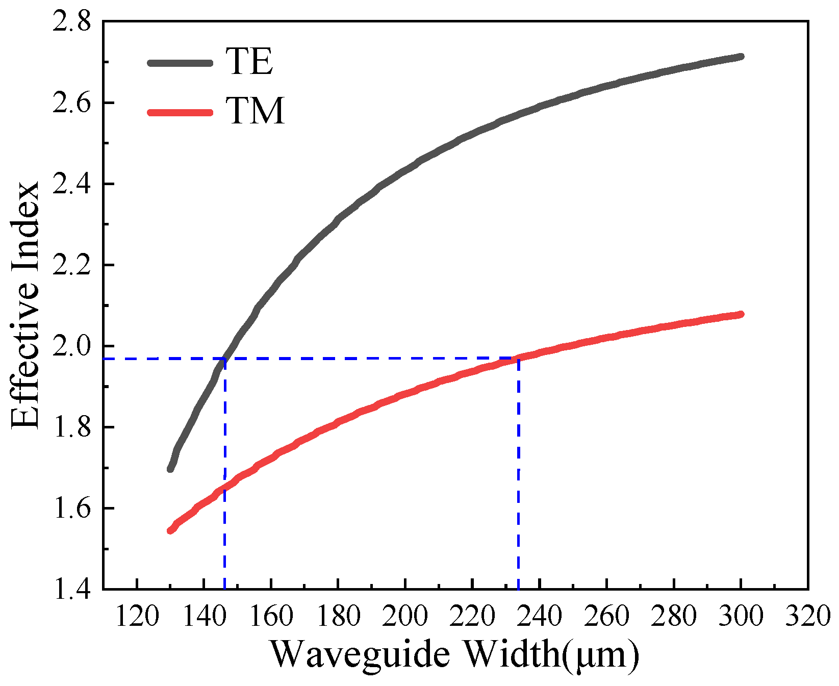
To determine the optimal structural parameters, a series of 3D-FDTD simulations are performed. The simulations were performed with a time step of 12.5591 fs. Perfectly matched layers (PMLs) were applied along the x-direction, while metallic boundary conditions were used along the y- and z-directions. The maximum mesh step was set to 0.25 nm to ensure numerical accuracy. The simulations were considered converged when the total electromagnetic energy in the computational domain decayed below 10−6 of its initial value, and the monitored transmission spectra showed negligible variations. The dependence of the TE and TM polarization modes in the THz-PSR waveguide on the waveguide width is shown in Figure 4, the simulation results shown in the figure is obtained at a terahertz frequency of 0.45 THz. Considering the PSR efficiency and fabrication complexity, the width of the input and coupling waveguides were chosen as W1 = 232 μm, W2 = 147 μm, respectively. Figure 3b illustrates the THz field distributions of the TE and TM polarization mode in the input waveguide.
Figure 4.
The effective index of the waveguide modes varies with the waveguide width. The blue line represents the phase-matching condition of TE and TM mode.
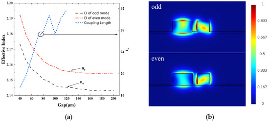
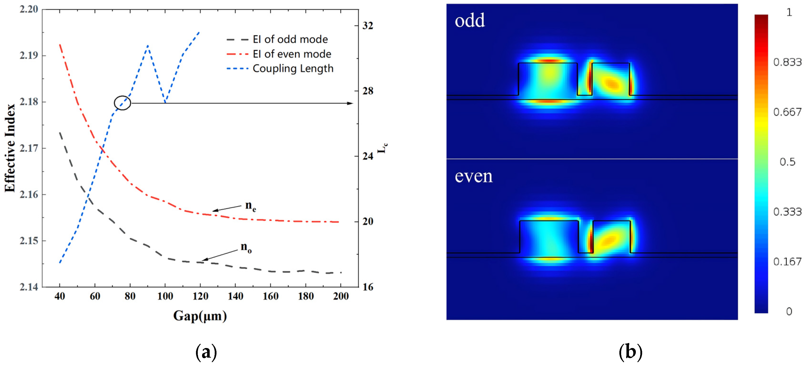
As the waveguide spacing varies, the effective index of the odd and even modes also change. Figure 5a shows the dependence of the effective indices of the odd and even modes for TE and TM polarizations on the waveguide spacing (Gap), where the simulations are performed at 0.45 THz. Based on the calculation results, the waveguide spacing was finally chosen as G = 60 μm. At this spacing, neven = 2.171811, nodd = 2.157256, and according to Equation (2), the coupling length of the designed device is calculated to be Lc = 22.9 mm. The THz field distribution of the even and odd mode in the PSR coupling region at this configuration are shown in Figure 5b.
Figure 5.
TM mode is converted to TE mode. (a) The influence of waveguide spacing Gap on the effective index of odd mode and even mode. (b) The THz field distribution of the even and odd mode.
3. Simulation and Analysis
3.1. Performance of the PSR
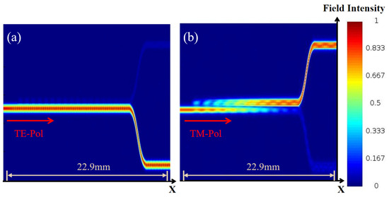
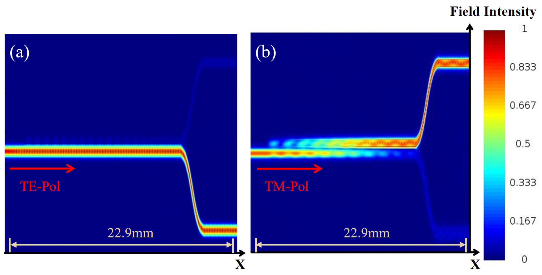
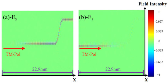
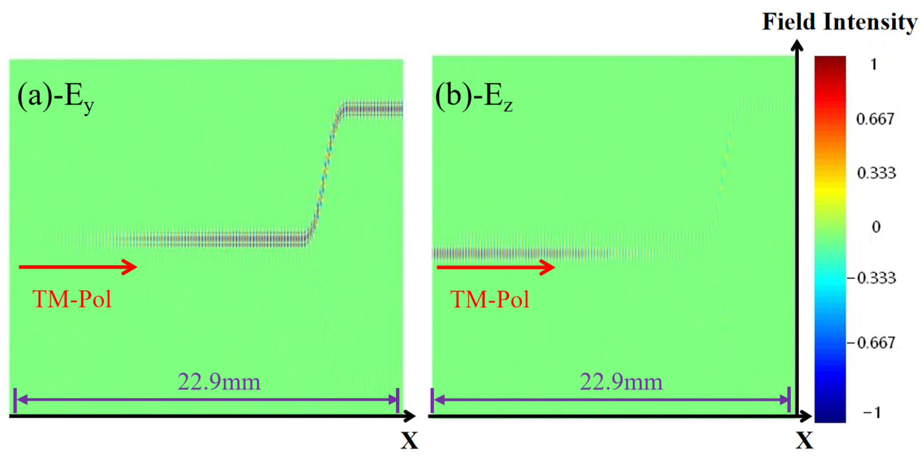
In this work, the 3D-FDTD method was employed to conduct simulation and analysis on the proposed PSR and its integrated structure with MZI. Figure 6 shows the THz field propagation of the PSR. At the frequency of 0.45 THz, the TE mode incident from the input waveguide propagates to output port 3 with minimal cross-coupling loss. When the TM mode is incident, the THz field is coupled into the adjacent waveguide within the coupling region, and the energy mainly output through the cross port 2. Figure 7 illustrates the modal evolution of the TM mode in the waveguide. After TM mode entering from the input port, the energy of the Ez component in the input waveguide gradually decreases, while the Ey component in the coupling waveguide increases correspondingly. This simulation result clearly demonstrates the polarization conversion process achieved by the proposed PSR device.
Figure 6.
PSR THz field propagation. (a) TE-pol; (b) TM-pol.
Figure 7.
Modal evolution of the TM mode in the waveguide. (a) Ey; (b) Ez.
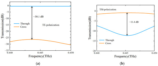
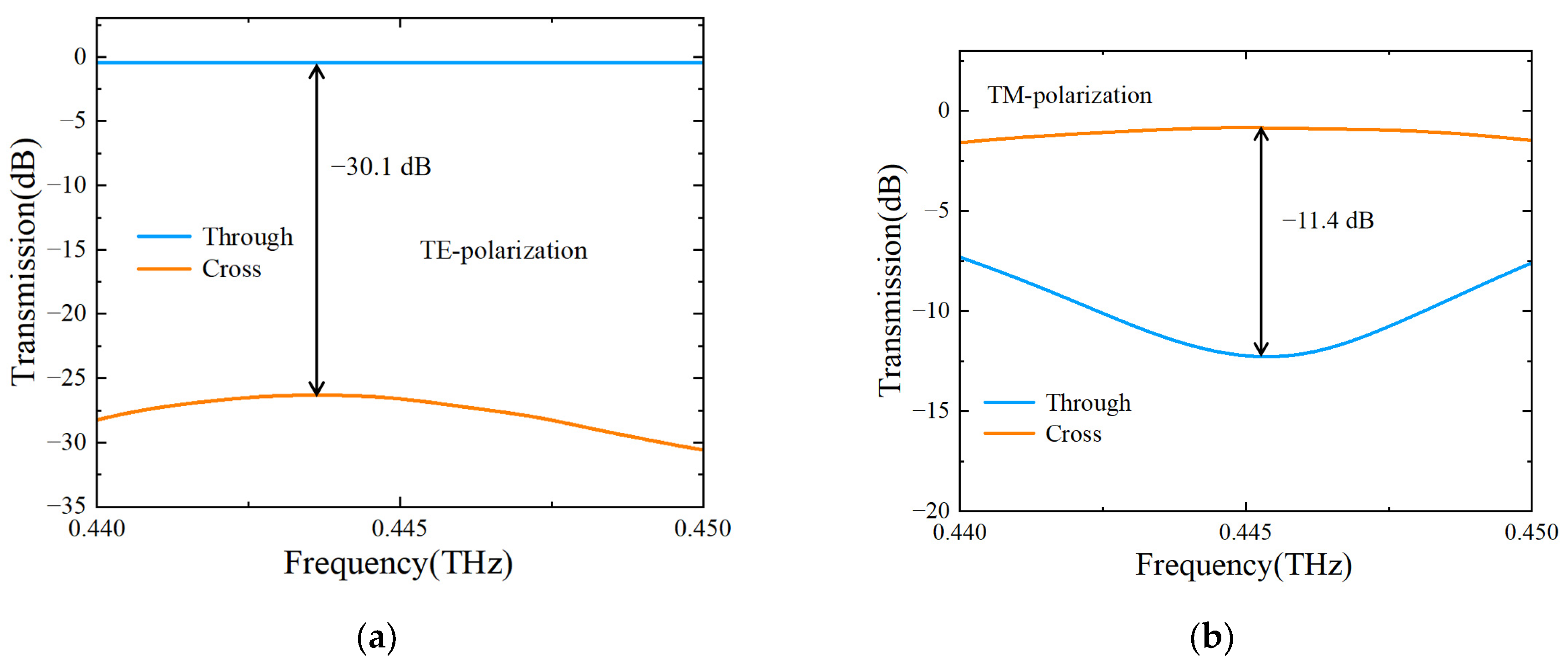
Figure 8 shows the spectral responses of the PSR under TE and TM incident modes. For the TE-mode, the maximum extinction ratio reaches −30.1 dB within the frequency range of 0.44 to 0.45 THz. The TE-TE insertion loss at the through port 3 is defined as , and the coupling loss at port 2 is defined as . As shown in Figure 8a, the TE-mode insertion loss is lower than –0.98 dB, and the coupling loss is also lower than –30 dB.
Figure 8.
Transmission spectra of the through port and cross port of the PSR. (a) TE-polarization; (b) TM-polarization.
For the TM-mode, the maximum extinction ratio is −11.4 dB. The polarization conversion efficiency (CE) of the TM mode is defined as . As illustrated in Figure 8b, the proposed PSR achieves a maximum polarization conversion efficiency of CE = 82.33%. The TM spectral response exhibits frequency dependence, primarily due to the mode coupling process is frequency-dependent. The simulation results indicate that the device demonstrates excellent overall polarization splitting and rotation performance.
3.2. Sensing Performance Analysis
We further evaluated the sensing performance of the PSR-integrated MZI sensor through the calculation. By integrating the PSR at the front end of the MZI sensor, a polarization-enhanced interferometric sensing unit is constructed. The purpose of this configuration is to convert arbitrary input polarization states into a unified TE mode using the PSR, ensuring that the light entering the MZI shares the same polarization state and thereby improving the overall interference quality.
In the simulations, the PSR is placed at the input of the device to preprocess the polarization state of the incident light. The lengths of the two arms of the MZI are both 4.9 mm. The straight waveguide connected to the through port 3 serves as the sensing arm, which is in contact with the biological medium under test, while the straight waveguide connected to the coupling port 3 as the reference arm. A broadband source with a central frequency of 0.45 THz is used for the simulations, the variation in the characteristic frequency is extracted to obtain information about the external biological environment.
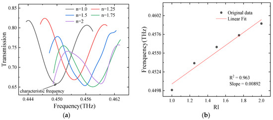
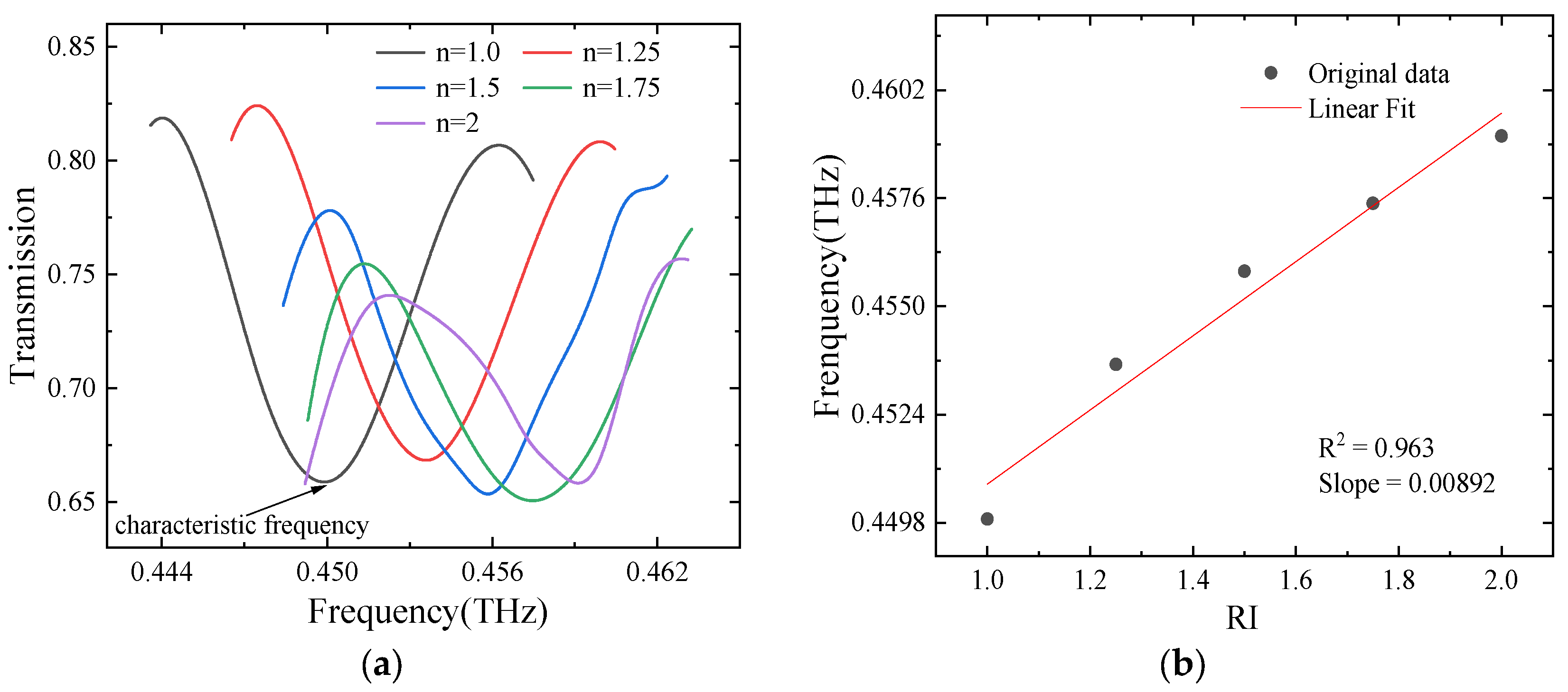
Figure 9 shows the transmission spectra of the MZI sensor within the frequency range of 0.44 to 0.46 THz. As observed, the transmission spectra exhibit a distinct blue shift as the external refractive index increases. Using the characteristic frequency of 0.449 THz extracted from the spectrum at n = 1.0, the sensitivity of the MZI sensor is calculated through simulation. Since the simulation results are obtained in the frequency domain, the corresponding wavelength is calculated using the relation where is the speed of light in vacuum and is the operating frequency. As shown in Figure 9b, the designed MZI sensor achieves a sensitivity of 13,215.81 nm/RIU.
Figure 9.
Refractive Index Response of the MZI Sensor. (a) Transmission Spectrum; (b) variation in frequency Shift with Refractive Index.
To further highlight the advantages of the proposed method, we compared the proposed device with several representative terahertz biosensors reported in the literature. The comparison results are summarized in Table 1.
Table 1.
Comparison of representative terahertz biosensors.
4. Conclusions
In summary, we propose a PSR-based, silicon-on-chip THz MZI biosensor for evaluating tendon injury severity and postoperative recovery. This device employs a polarization splitter and rotator to preprocess the incident light, converting arbitrary input polarization states into a unified TE mode. Simulation results show that the PSR exhibits a maximum extinction ratio of –30.1 dB for TE polarization and a maximum polarization conversion efficiency of 82.33% within the 0.44–0.45 THz range. In terms of sensing performance, the MZI sensor demonstrates a distinct interference spectrum in the THz band and exhibits a stable and observable blue shift in response to variations in the external refractive index. The results indicate that the proposed MZI biosensor achieves a high sensitivity of 13,215.81 nm/RIU near the center frequency of 0.45 THz, providing an effective solution for on-chip, highly sensitive THz biosensing applications. It should be noted that the present work is based on numerical simulations, and the proposed PSR–MZI biosensor has not yet been experimentally demonstrated, the reported performance is evaluated under idealized conditions. However, experimental implementation and validation of the proposed device will be essential, including device fabrication and terahertz measurement system development. In particular, the proposed sensor is expected to provide a potential tool for assisting clinicians in evaluating the severity of Achilles tendon injury and monitoring the recovery process. To achieve this goal, a systematic experimental study will be required to establish the relationship between the measured spectral response and the physiological state of tendon tissues. This includes analyte–concentration-dependent refractive index characterization, as well as calibration and demodulation of the output spectra with respect to different stages of tendon damage and healing. Such efforts will enable the extraction of meaningful physical and biomedical information from the measured terahertz spectra and further promote the practical application of the proposed sensing system.
Author Contributions
Project administration, Z.Y.; writing—original draft preparation, Y.L.; supervision, Q.P.; data curation, T.Z.; writing—review and editing, G.D. All authors have read and agreed to the published version of the manuscript.
Funding
This research was funded by National Natural Science Foundation of China, grant number 82302354 and National Natural Science Foundation of China, grant number 62305017.
Institutional Review Board Statement
Not applicable.
Data Availability Statement
The raw data supporting the conclusions of this article will be made available by the authors on request.
Conflicts of Interest
Author Qunzhen Peng was employed by the company China Aerospace Science and Industry Corporation (CASIC) Second Academy. The remaining authors declare that the research was conducted in the absence of any commercial or financial relationships that could be construed as a potential conflict of interest.
Abbreviations
The following abbreviations are used in this manuscript:
| MZI | Mach–Zehnder Interferometer |
| PSR | Polarization Splitter and Rotator |
| FDTD | Finite Difference Time Domain |
| THz | Terahertz |
| TE | Transverse Electric |
| TM | Transverse Magnetic |
| Pol | Polarization |
References
- Lin, R.; Gao, H.; Lou, J.; Xu, J.; Yin, M.; Wu, P.; Liu, C.; Guo, Y.; Wang, E.; Yang, S.; et al. All-perovskite tandem solar cells with dipolar passivation. Nature 2025, 648, 600–606. [Google Scholar] [CrossRef] [Scilit]
- Zhang, J.; Lou, J.; Wang, Z.; Liang, J.; Zhao, X.; Huang, Y.; Chang, C.; Hu, G. Photon-Induced Ultrafast Multitemporal Programming of Terahertz Metadevices. Adv. Mater. 2025, 37, 2570052. [Google Scholar] [CrossRef] [Scilit]
- Sun, S.; Wang, B.; Liu, K.; Harrington, M.; Tabatabaei, F.; Liu, R.; Wang, J.; Hanifi, S.; Hanifi, S.; Morgan, J.; et al. Integrated optical frequency division for microwave and mmWave generation. Nature 2024, 627, 540–545. [Google Scholar] [CrossRef] [Scilit]
- Zhu, S.; Zhang, Y.; Feng, J.; Wang, Y.; Zhai, K.; Feng, H.; Pun, E.; Zhu, N.; Wang, C. Integrated lithium niobate photonic millimetre-wave radar. Nat. Photonics 2025, 19, 204–211. [Google Scholar] [CrossRef] [Scilit]
- Liao, K.; Lian, Y.; Yu, M.; Du, Z.; Dai, T.; Wang, Y.; Yan, H.; Wang, S.; Lu, C.; Chan, C.; et al. Hetero-integrated perovskite/Si3N4 on-chip photonic system. Nat. Photonics 2025, 19, 358–368. [Google Scholar] [CrossRef] [Scilit]
- Quack, N.; Takabayashi, A.; Sattari, H.; Edinger, P.; Jo, G.; Bleiker, S.; Errando-Herranz, C.; Gylfason, K.; Niklaus, F.; Khan, U.; et al. Integrated silicon photonic MEMS. Microsyst. Nanoeng. 2023, 9, 27. [Google Scholar] [CrossRef] [Scilit]
- Lin, H.; Luo, Z.H.; Gu, T.; Kimerling, L.; Wada, K.; Agarwal, A.; Hu, J. Mid-infrared integrated photonics on silicon: A perspective. Nanophotonics 2018, 7, 393–420. [Google Scholar] [CrossRef] [Scilit]
- Luan, E.; Shoman, H.; Ratner, D.; Cheung, K.; Chrostowski, L. Silicon Photonic Biosensors Using Label-Free Detection. Sensors 2018, 18, 3519. [Google Scholar] [CrossRef] [Scilit]
- Kong, Z.; Li, Y.; Yang, G.; Sang, T.; Wang, Y. Polarization beam splitter based on multimode interference of coupled topological edge states. Opt. Commun. 2025, 592, 132235. [Google Scholar] [CrossRef] [Scilit]
- Li, J.; Liu, H.; Zhang, L. Terahertz wave polarization beam splitter using a cascaded multimode interference structure. Appl. Opt. 2014, 53, 5024–5028. [Google Scholar] [CrossRef] [Scilit]
- Pei, X.; Bao, L.; Wang, Q.; Wu, B.; Fu, P.; Zhou, H.; Deng, J.; Ni, P.; Kan, Q.; Chen, P.; et al. On-chip Integration of Metasurface-Based Beam Splitter with Variable Split Ratio. Laser Photonics Rev. 2025, 19, 2500140. [Google Scholar] [CrossRef] [Scilit]
- Bai, Y.; Wang, P.; Peng, B.; Chu, T. O-band reconfigurable silicon polarization rotator. Chin. Opt. Lett. 2024, 22, 011303. [Google Scholar] [CrossRef] [Scilit]
- Deng, H.; Yevick, D.; Chaudhuri, S. Bending characteristics of asymmetric SOI polarization rotators. IEEE Photonics Technol. Lett. 2025, 17, 2113–2115. [Google Scholar] [CrossRef] [Scilit]
- Alonso-Ramos, C.; Halir, R.; Ortega-Moñux, A.; Cheben, P.; Vivien, L.; Molina-Fernández, Í.; Marris-Morini, D.; Janz, S.; Xu, D.; Schmid, J. Highly tolerant tunable waveguide polarization rotator scheme. Opt. Lett. 2012, 37, 3534–3536. [Google Scholar] [CrossRef] [Scilit]
- Wang, Z.C.; Dai, D.X. Ultrasmall Si-nanowire-based polarization rotator. J. Opt. Soc. Am. B 2008, 25, 747–753. [Google Scholar] [CrossRef] [Scilit]
- Xiong, Y.; Xu, D.X.; Schmid, J.H.; Cheben, P.; Janz, S.; Ye, W.N. Fabrication tolerant and broadband polarization splitter and rotator based on a taper-etched directional coupler. Opt. Express 2014, 22, 17458–17465. [Google Scholar] [CrossRef] [Scilit]
- Bai, B.; Pei, L.; Zheng, J.; Ning, T.; Li, J. Ultra-short plasmonic polarization beam splitter-rotator using a bent directional coupler. Chin. Opt. Lett. 2020, 18, 041301. [Google Scholar] [CrossRef] [Scilit]
- Navaratna, N.; Tan, Y.; Wang, W.; Singh, R. Monolithic Terahertz Topological Mach-Zehnder Interferometer. Adv. Mater. 2025, 37, 2505657. [Google Scholar] [CrossRef] [Scilit]
- Torres-Cubillo, A.; Sánchez-Postigo, A.; Jágerská, J.; Wangüemert-Pérez, J.; Halir, R. Simultaneous measurement of refraction and absorption with an integrated near-infrared Mach–Zehnder interferometer. Opt. Laser. Technol. 2024, 177, 111154. [Google Scholar] [CrossRef] [Scilit]
- Wahsheh, R. Plasmonic Mach-Zehnder Interferometers Based on Air-Gap Couplers. IEEE Photonics J. 2023, 15, 1–10. [Google Scholar] [CrossRef] [Scilit]
- Ran, J.; Li, Y.; Cai, Z.; Zhang, J.; Liu, X.; Lu, Y.; Zheng, Z.; Chen, Q.; Xu, O.; Dong, X.; et al. On-Chip Glucose Sensor with a Microstructure Gap for Sensitivity Enhancement. J. Light. Technol. 2025, 43, 9481–9487. [Google Scholar] [CrossRef] [Scilit]
- Xiao, L.; Chen, X.; Li, X.; Zhang, J.; Wang, Y.; Li, D.; Hong, X.; Shao, Y.; Chen, Y. Enhanced Sensitivity Mach–Zehnder Interferometer-Based Tapered-in-Tapered Fiber-Optic Biosensor for the Immunoassay of C-Reactive Protein. Biosensors 2025, 15, 90. [Google Scholar] [CrossRef] [Scilit]
- Peng, Y.; Ye, Y.; Liu, J.; Qin, S.; Zhao, Y. Label-free detection of bovine serum albumin based on a microfiber biosensor with controllable optimized structure. Sens. Actuators A Phys. 2024, 375, 115543. [Google Scholar] [CrossRef] [Scilit]
- El Shamy, R.S.; Swillam, M.A.; Khalil, D.A. Mid Infrared Integrated MZI Gas Sensor Using Suspended Silicon Waveguide. J. Light. Technol. 2019, 37, 4394–4400. [Google Scholar] [CrossRef] [Scilit]
- Ma, X.; Chen, K.; Wu, J. Cost-Effective Mach-Zehnder Interferometer Liquid Refractive Index Sensor Based on Conventional Polymer Strip Waveguide. IEEE Photonics J. 2021, 13, 6600109. [Google Scholar] [CrossRef] [Scilit]
- Doughan, I.; Oyemakinwa, K.; Ovaskainen, O.; Roussey, M. Strip-loaded Mach–Zehnder interferometer for absolute refractive index sensing. Sci. Rep. 2024, 14, 3064. [Google Scholar] [CrossRef] [Scilit]
- Zhang, Z.; Wang, Z.; Zhang, C.; Yao, Z.; Zhang, S.; Wang, R.; Tian, Z.; Han, J.; Chang, C.; Lou, J.; et al. Advanced Terahertz Refractive Sensing and Fingerprint Recognition Through Metasurface-Excited Surface Waves. Adv. Mater. 2024, 36, 2308453. [Google Scholar] [CrossRef] [Scilit]
- Jiao, Y.; Lou, J.; Ma, Z.; Cong, L.; Xu, X.; Zhang, B.; Li, D.; Yu, Y.; Sun, W.; Yan, Y.; et al. Photoactive terahertz metasurfaces for ultrafast switchable sensing of colorectal cells. Mater. Horiz. 2022, 9, 2984–2992. [Google Scholar] [CrossRef] [Scilit]
- Lou, J.; Jiao, Y.; Yang, R.; Huang, Y.; Xu, X.; Zhang, L.; Ma, Z.; Yu, Y.; Peng, W.; Yuan, Y.; et al. Calibration-free, high-precision, and robust terahertz ultrafast metasurfaces for monitoring gastric cancers. Proc. Natl. Acad. Sci. USA 2022, 119, e2209218119. [Google Scholar] [CrossRef] [Scilit]



Disclaimer/Publisher’s Note: The statements, opinions and data contained in all publications are solely those of the individual author(s) and contributor(s) and not of MDPI and/or the editor(s). MDPI and/or the editor(s) disclaim responsibility for any injury to people or property resulting from any ideas, methods, instructions or products referred to in the content. |
© 2026 by the authors. Licensee MDPI, Basel, Switzerland. This article is an open access article distributed under the terms and conditions of the Creative Commons Attribution (CC BY) license.