


Abstract
Based on vector wave aberration theory, this paper analyzes the relative positions of the third-order coma node and astigmatism nodes under pupil decenter and proposes an initial structure selection criterion in which the coma node coincides with the geometric midpoint of the two astigmatism nodes. Using this criterion, an F/6 off-axis catadioptric telephoto optical system with a focal length of 900 mm and an entrance pupil diameter of 150 mm was designed. The measured on-axis RMS wavefront error was better than 0.025λ at 632.8 nm. The results demonstrate that the system meets the requirements for high-resolution long-focal-length imaging.
1. Introduction
Off-axis catadioptric optical systems have been widely used in high-power laser delivery, space- and ground-based wide-field imaging, compact freeform telescopes, and large-aperture antenna metrology owing to their unobscured aperture, foldable optical path, and achromatic reflective propagation [1,2,3,4]. In recent years, advances in freeform fabrication and alignment techniques have accelerated the development of unobscured off-axis reflective systems. Representative examples include all-aluminum two-mirror freeform imaging telescopes [5], compact off-axis three-mirror reflective systems [6], direct construction and optimization methods for freeform off-axis three-mirror systems [7], equal-optical-path-based design methods for off-axis freeform imaging systems [8], and application-oriented freeform off-axis three-mirror or zoom systems [9,10,11,12]. These studies highlight the strong engineering potential of off-axis optical systems in imaging applications.
However, the non-rotationally symmetric nature of off-axis systems results in complex aberration coupling and highly field-dependent aberration distributions. In particular, under pupil decenter, the full-field distributions of major third-order aberrations such as coma and astigmatism deviate from the simple rules that apply to rotationally symmetric systems. Consequently, the choice of initial structure is critical to both optimization efficiency and final performance. Although existing designs often rely on numerical optimization and empirical iteration, vector aberration theory expresses the relationships among aberration, field, and pupil in nonsymmetric systems using vector forms, providing a powerful tool for physical analysis and structural design of off-axis systems [13,14,15]. While vector-aberration-based analyses and initial structure construction methods for off-axis reflective systems have been reported [16], a concise geometric criterion directly applicable to engineering-oriented initial parameter selection is still lacking.
To address this gap, the present study analyzes the field location behavior of the third-order coma node and astigmatism nodes under pupil decenter within the framework of vector wave aberration theory, derives their quantitative positional relationship, and proposes an initial structure selection criterion characterized by the coincidence of the coma node with the geometric midpoint of the two astigmatism nodes. Compared with conventional empirical iteration or direct numerical optimization approaches, the proposed criterion directly exploits the geometric distribution of the dominant third-order aberration fields and thus offers a more physically meaningful basis for initial structure construction in off-axis systems. For the unidirectionally decentered two-mirror off-axis system considered here, the method reduces the original two-dimensional evaluation problem in off-axis parameter space to a one-dimensional search along a constrained path, significantly simplifying initial structure selection and improving subsequent optimization accessibility. To verify the engineering effectiveness of the proposed method, an F/6 off-axis catadioptric telephoto optical system was designed and its performance was evaluated through image quality analysis and post-fabrication alignment testing.
2. Vector Aberration Theory for Pupil-Decentered Systems and Its Application
Given the requirements of long-focal-length imaging systems for clear detection of distant targets and compact structural layout, an off-axis catadioptric configuration with a real focus was adopted to achieve high-quality imaging of distant objects onto the focal plane sensor [17]. In general, an off-axis reflective optical system can be derived from its rotationally symmetric parent system through field decenter, pupil decenter, or a combination of both, thereby forming a nonsymmetric optical configuration. Such systems not only eliminate the central obscuration inherent in conventional coaxial systems, thus improving optical throughput and image quality, but also provide greater flexibility for aberration control through appropriate spatial arrangement of the optical elements.
Shack and co-workers expressed the field and pupil in vector form and established the vector wave aberration function [18,19]. Based on geometrical optics, the propagation path of an arbitrary ray can be uniquely determined by a linear combination of the field vector and the pupil vector.
where represents the normalized field vector, is the normalized pupil vector, and are the primary wave aberration coefficients of different surfaces.
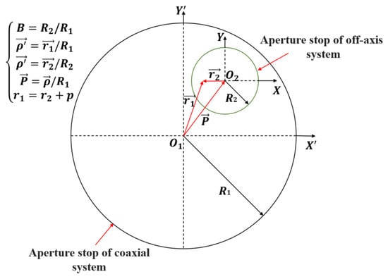
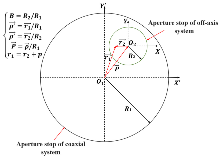
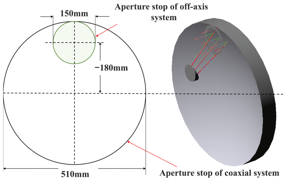
For off-axis reflective systems, the aperture pupil is compressed and shifted relative to the corresponding on-axis system. The relationship between the off-axis system and its on-axis counterpart is shown in Figure 1.
where is the normalized pupil vector of the off-axis system, is the pupil scaling factor between off-axis and on-axis systems, and is the offset vector representing the pupil decenter (off-axis amount).
Figure 1.
Schematic of the pupil relationship between the coaxial parent system and the off-axis reflective system.
Substituting Equation (2) into the primary vector wave aberration formula (Equation (1)) of the on-axis system yields the primary vector wave aberration for the off-axis system:
Due to the introduced pupil decenter parameters, the aberration center of the off-axis system no longer coincides with the ideal image plane center, and the field dependence of the aberrations changes. The third-order wave aberration coefficients for the off-axis pupil system can be expressed as (Equation (4)):
Vector aberration theory presents the variations of third-order aberrations in off-axis systems in the form of analytical expressions. The spherical aberration, coma aberration, astigmatism, field curvature, and distortion in the off-axis system were analyzed respectively.
It should be noted that the criterion in this section is used for initial parameter selection in off-axis systems, prioritizing coma and astigmatism, which are the most sensitive and likely to cause uneven aberration distribution. Spherical aberration is field-independent and cannot be used for node selection; distortion mainly affects image mapping and is controlled as a parallel constraint during subsequent optimization; field curvature is coupled with the image plane position and is evaluated alongside RMS wavefront error during full-system optimization. Therefore, only the relative positions of coma and astigmatism nodes are selected as the basis for initial parameter selection.
From the field vector relationships in Table 1, the third-order aberrations in off-axis systems show significant field dependence: coma varies linearly with field, astigmatism varies quadratically. Therefore, in the two-dimensional field plane, there is one coma node and two astigmatism nodes. In the initial off-axis parameter selection stage, under unobscured constraints, aligning the geometric center of the two astigmatism nodes with the coma node helps balance major third-order aberration distribution, reducing RMS wavefront error across the full field and providing a better initial structure for subsequent optimization.
Table 1.
Relationship of third-order aberrations of optical systems.
The relevant expressions are:
where represents half the separation between the two astigmatism nodes, and denote the tilt and decenter off-axis parameters of the jth surface, and m is the number of optical surfaces contributing to the aberration. To extract the nodes in Equation (7), a one-dimensional field coordinate H along the system principal field is used. Denote the coma node coordinate along this direction as, and the astigmatism node coordinates as Ha1, Ha2. Then Equation (7) is equivalent to: .
Equation (7) expresses the constraint for coincidence of coma node and the geometric midpoint of the astigmatism nodes. Physically, under unobscured conditions, adjusting off-axis structural parameters to satisfy this constraint allows the major third-order aberrations to partially cancel across the working field, reducing RMS wavefront error.
For a general off-axis system, the node matching error can be expressed as a two-dimensional function of the pupil scaling factor and offset parameter E(B,P). For the two-mirror off-axis system studied here, constrained along the Y-direction only, the two-dimensional off-axis parameter space reduces to a one-dimensional search along the feasible path.
Relating normalized parameters in Equation (2) to actual dimensions: let the parent system entrance pupil radius be Rp, and the off-axis sub-aperture entrance pupil radius be Rs. The pupil scaling factor is:
If the actual sub-aperture offset relative to the parent system pupil center is , the normalized offset magnitude satisfies:
Thus, B and P jointly determine the position and effective size of the off-axis sub-aperture, directly affecting the field distribution of third-order aberrations. In this single-direction off-axis system, the primary mirror Y-direction off-axis is the main scan variable. The secondary mirror offset is not an independent scan parameter but is determined by ray tracing and unobscured constraints for each . Therefore, once is fixed, the off-axis sub-aperture position and effective aperture are determined, making B and P functions of , B(), and P(). The original two-dimensional node matching error E(B,P) degenerates to a one-dimensional function along the constrained path:
where Hc() is the coma node coordinate along the principal field; Ha1(), Ha2() are the two astigmatism node coordinates. The smaller E(), the closer the coma node is to the geometric midpoint of the astigmatism nodes, yielding a balanced major third-order aberration distribution and a reasonable initial structure for subsequent image quality optimization.
The node-matching error function E() defined in Equation (11) has a clear physical interpretation: it quantifies the spatial misalignment between the zero-crossing location of the third-order coma field (Hc) and the geometric midpoint of the two astigmatism nodes (Hamid) along the principal field direction. When E = 0, the coma node coincides with the midpoint of the astigmatism nodes, meaning that the coma aberration distribution is symmetric about the axis of symmetry of the astigmatism field. Under this condition, the dominant third-order aberrations partially cancel each other across the working field, resulting in a more uniform and minimized full-field RMS wavefront error. Conversely, a large E indicates that the peak regions of coma and astigmatism are spatially misaligned across the field, preventing effective aberration cancellation and leading to elevated RMS wavefront error at certain field positions. Therefore, minimizing E serves as a physically meaningful surrogate criterion for achieving balanced third-order aberration distribution in the initial off-axis parameter selection stage.
3. Design Example and Off-Axis Parameter Selection
As a design example, an off-axis catadioptric long-focus lens was implemented. The system employs a Sony IMX410 CMOS sensor (Sony, Tokyo, Japan) with pixel size 5.94 μm, corresponding to a Nyquist sampling frequency of 84.2 lp/mm. The sensor’s effective imaging area is 36 mm × 24 mm; via ROI cropping this is reduced to a 12.2 mm × 12.2 mm square region, yielding a system field of view of 1.4° × 1.4° (diagonal 1.98°).
To ensure image quality, the system requires high resolution and low aberrations. Based on sensor size and resolution requirements, the off-axis catadioptric system focal length was set to 900 mm. For high-resolution imaging, F-number is chosen as F = 6, corresponding to an entrance pupil diameter D = 150 mm. The main design parameters of the long-focus lens are summarized in Table 2. The system adopts an off-axis catadioptric structure to achieve unobscured, high-contrast imaging. Collimated light is sequentially reflected by the primary and secondary mirrors and then corrected by a three-lens group before reaching the focal plane sensor.
Table 2.
Design parameters of the optical systems.
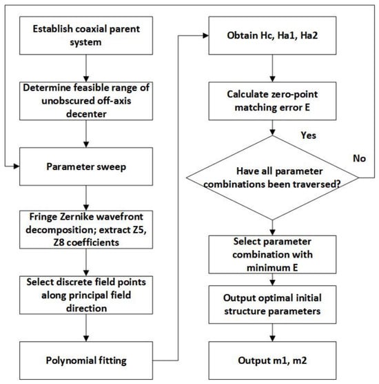
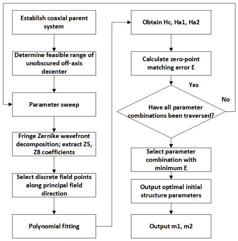
Based on the criterion presented in Section 2, the initial off-axis parameter selection is divided into three steps: Parameter sweep—wavefront decomposition and node extraction—matching error evaluation, and initial value selection (Figure 2).
Figure 2.
Flow chart of initial structure selection for the off-axis optical system based on vector aberration theory.
3.1. Parameter Sweep
The coaxial parent system was built in optical design software, its entrance pupil radius was read, and the off-axis sub-aperture radius was determined. Under structural and unobscured constraints, a feasible scan range for the primary mirror off-axis amount m1 was defined. A coarse sweep with 20 mm steps was first performed to locate regions of low node matching error E, followed by a fine sweep with 5 mm steps. For each candidate m1, the secondary mirror offset m2 was adjusted via ray tracing to exclude solutions with obscuration.
3.2. Wavefront Decomposition and Node Extraction
For each unobscured off-axis parameter set, the exit pupil wavefront was decomposed using Fringe Zernike polynomials. Along the principal field, nine discrete field points were selected to compute the Zernike coefficients. The primary coma components Z7, Z8 and astigmatism components Z5, Z6 were extracted (Z6, Z7 0, consistent with Y-direction pupil decenter symmetry). The coma node Hc was obtained via linear fitting of Z8, and the astigmatism nodes Ha1, Ha2 via quadratic fitting of Z5; their geometric midpoint is Hamid.
3.3. Matching Error Evaluation and Initial Value Selection
The node matching error is defined as E = ∣Hc − Hamid∣. The parameter set (m1, m2) with minimum E was chosen as the optimal initial off-axis parameters.
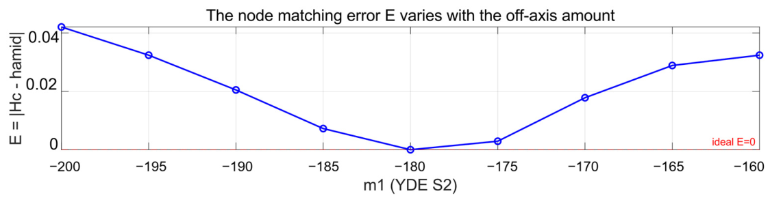
Through this procedure, the minimum E occurs at m1 = −180 mm and m2 = 45 mm. This parameter combination represents the set with the minimum E within the current scanning range. In this configuration, the coma node along the system’s principal field direction is closest to the geometric midpoint of the two astigmatism nodes, providing a reasonably optimal initial solution that satisfies the current unobscured constraints and aberration balance requirements.
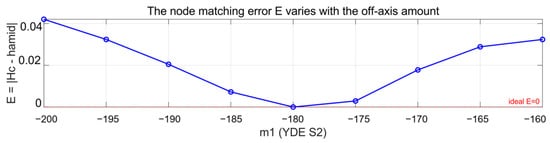
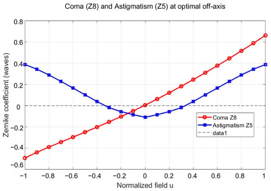
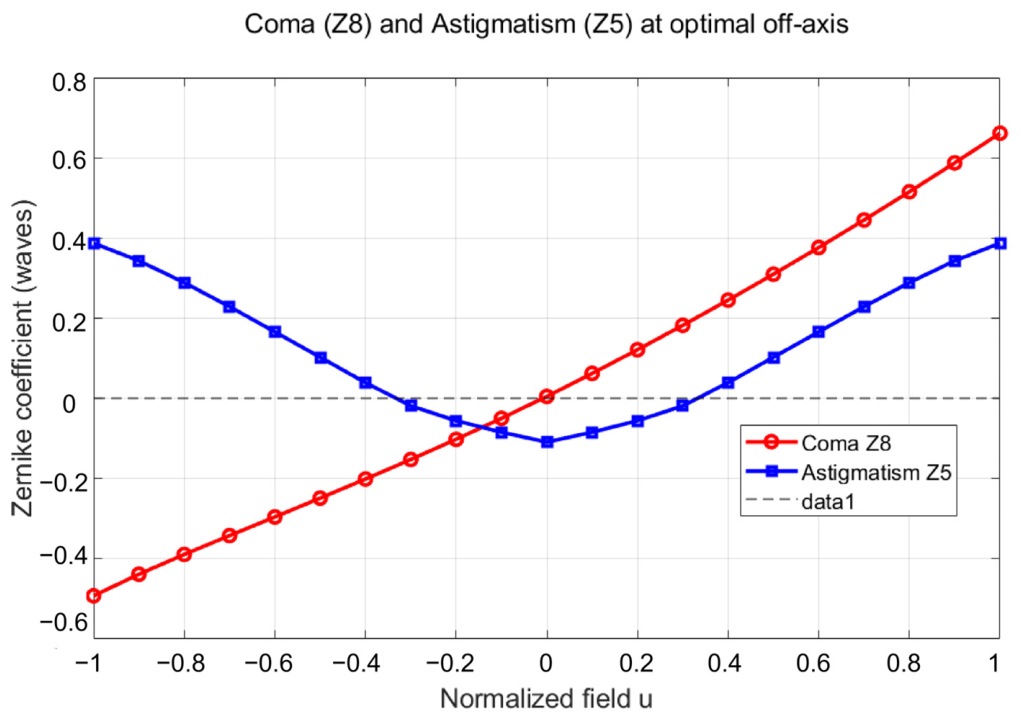
Figure 3 presents the off-axis parameter sweep results based on the node matching criterion. Figure 4 shows the variation of Z5 and Z8 with normalized field under the optimal off-axis parameters. As can be seen, Z8 has only a single zero-crossing point, whereas Z5 exhibits two zero-crossing points. Furthermore, the coma node position is close to the geometric midpoint of the two astigmatism nodes. This observation is consistent with the theoretical analysis presented earlier, indicating that the initial value selection method based on the node matching criterion effectively narrows the initial search space for the off-axis system, and provides a reasonable starting point for subsequent fine optimization.
Figure 3.
Off-axis parameter scan results based on the node matching criterion.
Figure 4.
Variation of coma (Z8) and astigmatism (Z5) with normalized field at optimal off-axis parameters (m1 = −180 mm, m2 = 45 mm).
4. Design Results and Performance Evaluation
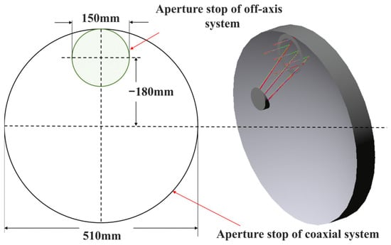
Based on vector aberration theory and the specific project requirements, an off-axis catadioptric long-focus imaging system was designed. The reflective primary structure uses an off-axis folded telescope configuration, followed by a three-lens correction group. Both primary and secondary mirrors are conic surfaces. By introducing a pupil decenter of 180 mm along the −Y direction, the system achieves an unobscured optical design. The calculated pupil scaling factor is approximately B = 0.294, and the corresponding transformation is shown in Figure 5.
Figure 5.
The optical path structure of the off-axis telescope and its pupil transformation relationship with the on-axis parent system.
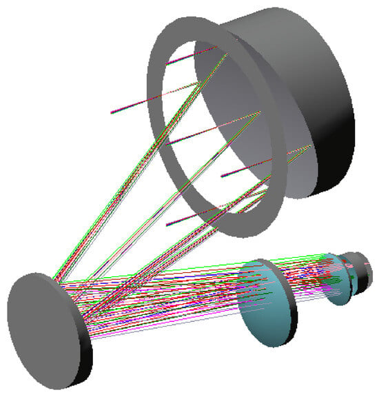
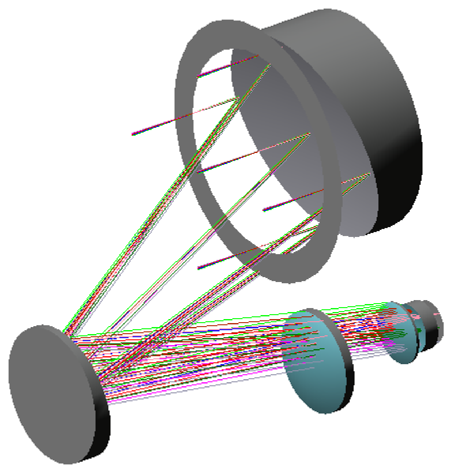
Using the initial off-axis structure determined in the previous section, the reflective primary structure and subsequent correction group were jointly optimized. The final off-axis catadioptric long-focus system layout is shown in Figure 6. The optical paths are unobstructed and complete. The structural parameters of the primary and secondary mirrors are summarized in Table 3.
Figure 6.
Optical path layout of off-axis system.
Table 3.
Structural parameters of optical systems.
Combining the parameter scan results of the node-matching error function E shown in Figure 4, E decreases rapidly to its minimum value of E = 2.4 × 10⁻⁴ (normalized field, dimensionless) as m1 approaches −180 mm. At this point, the distance between the coma node and the midpoint of the two astigmatism nodes is 0.00891 (normalized field), indicating that the nodes are closest and nearly coincident. This causes the nodal distance to shrink accordingly, thereby achieving optimal node alignment. This quantitative result directly validates the vector wave aberration theory by demonstrating the physical mechanism behind the coincidence of coma and astigmatism nodes. The theoretical optimal alignment is further confirmed by the measured interferograms in Section 4.2: in (a) the wavefront map exhibits low coma (0.119) and astigmatism (0.019) contributions with highly uniform fringes, while in (b) the off-axis case maintains balanced coma (0.154) and astigmatism (0.054) terms, resulting in the lowest full-field RMS wavefront error.
4.1. Image Quality Evaluation
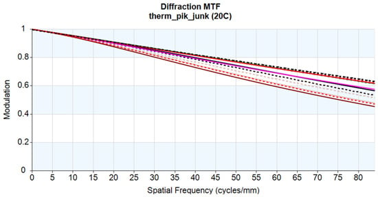
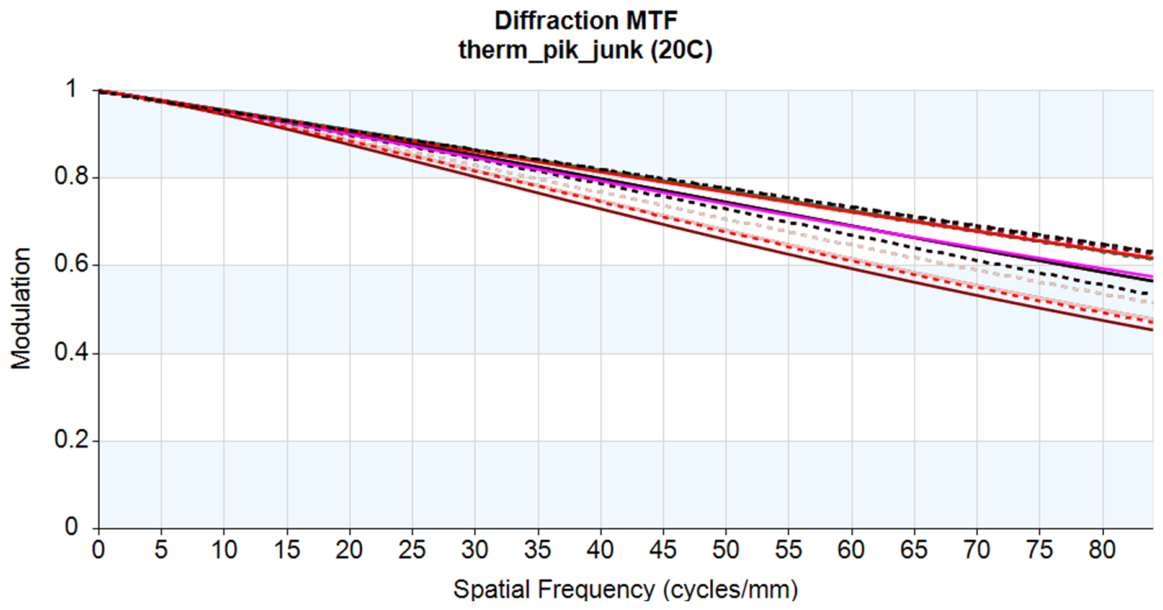
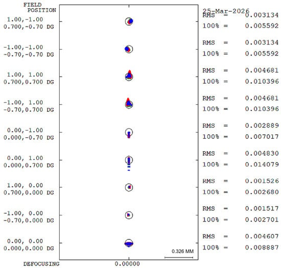
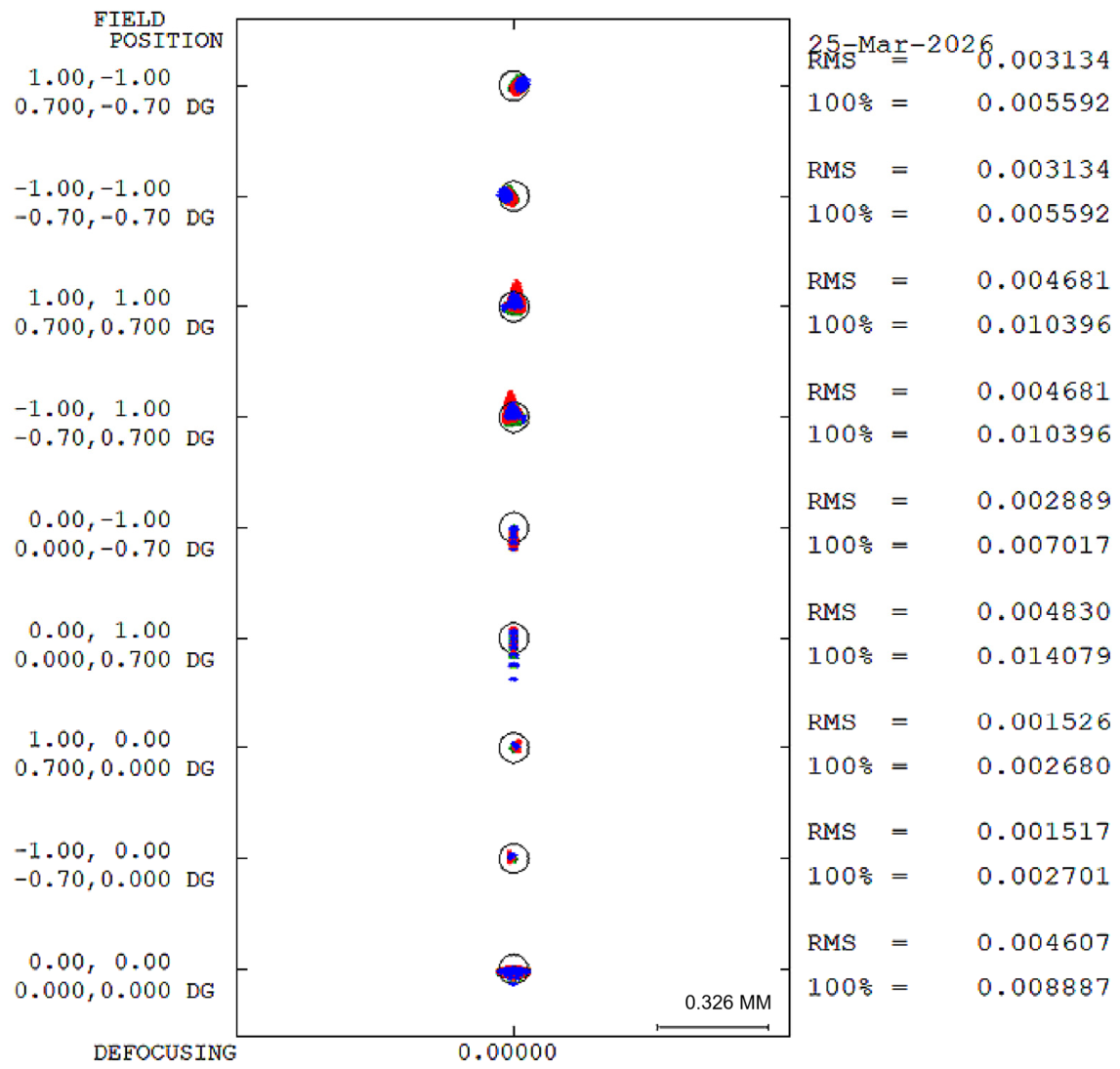
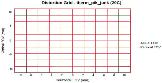
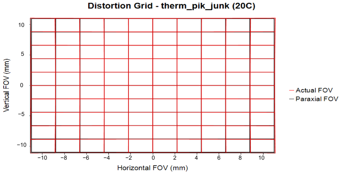
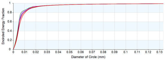
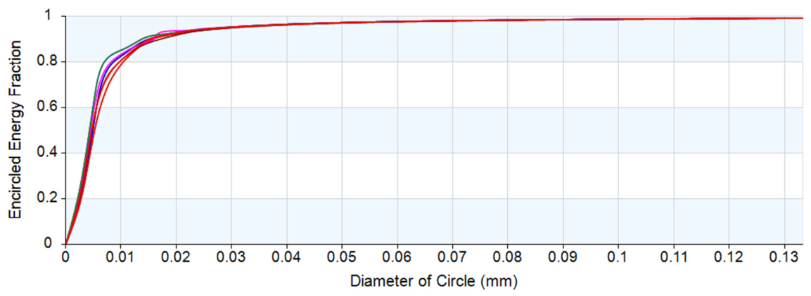
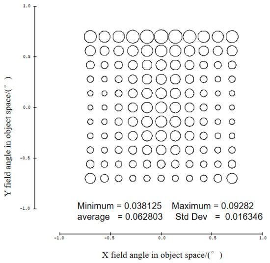
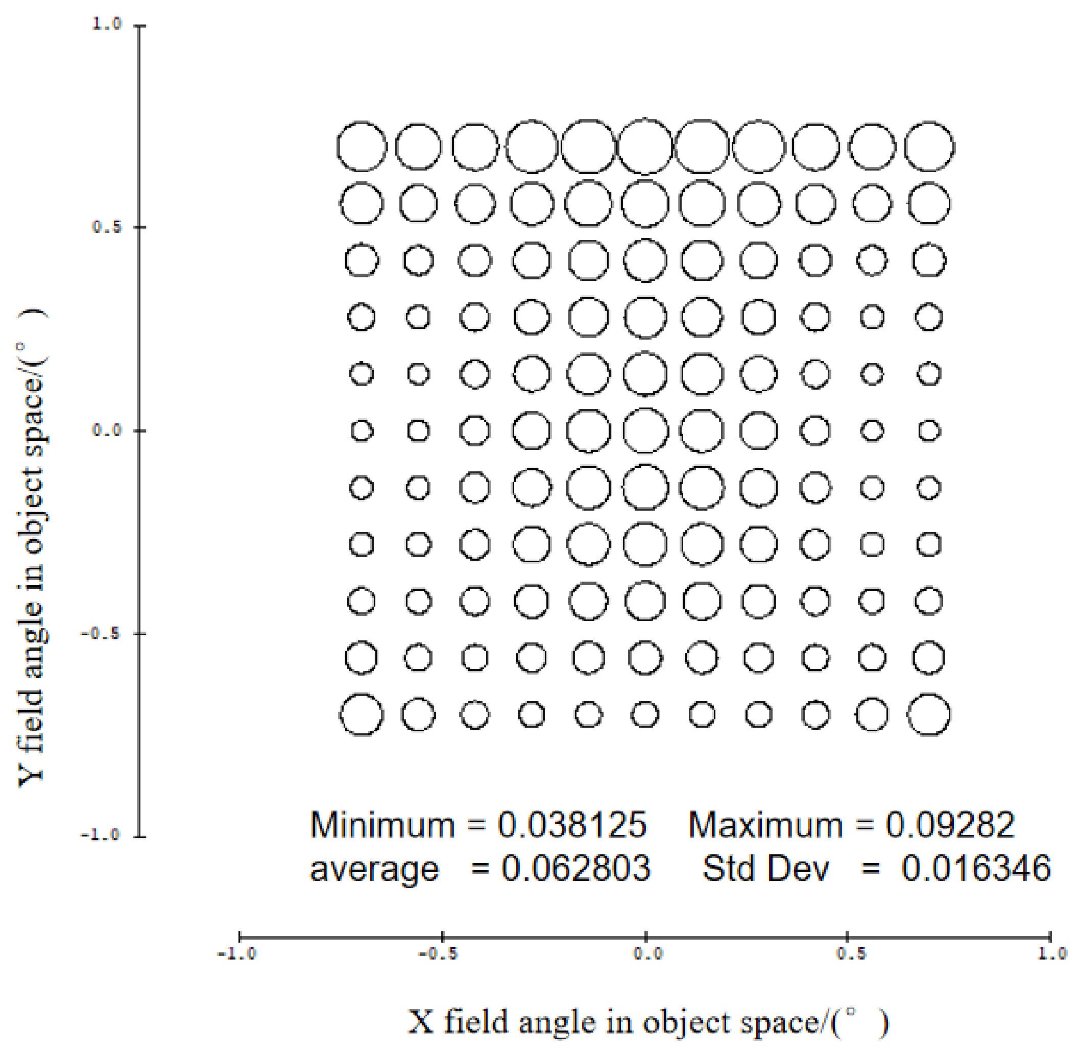
The full-field MTF is greater than 0.4 at 85 lp/mm (Figure 7). Spot diagrams and distortion grids are shown in Figure 8 and Figure 9. To meet the geometric precision requirements for long-focus imaging of distant targets, distortion was strictly controlled to ensure uniform image scale and accurate angular mapping. The encircled energy distribution is shown in Figure 10, with 80% of the energy concentrated within a radius of 5 μm. RMS wavefront error across the full field is shown in Figure 11, with a maximum value of 0.095λ (λ = 632.8 nm) and all field points below λ/9.7. These results indicate that the system achieves the required high-resolution imaging performance.
Figure 7.
Modulation transfer functions of the optical system. Different colors correspond to different fields of view.
Figure 8.
Spot diagrams of the optical system.
Figure 9.
Distortion grid of the optical system.
Figure 10.
Encircled energy distributions of the optical system. Different colors correspond to different fields of view.
Figure 11.
Full-field RMS wavefront error of the optical system.
4.2. Tolerance Analysis
In the actual production process, the parameters of the optical system will change to varying degrees, deviating from the theoretical values and resulting in degraded imaging quality. Therefore, tolerance analysis must be performed to predict the final imaging performance of the fabricated system. According to the current actual manufacturing capability for off-axis conic mirrors and spherical correction lenses, the tolerance conditions that can be achieved at a reasonable cost are listed in Table 4.
Table 4.
Tolerance.
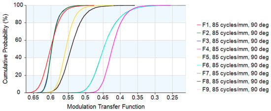
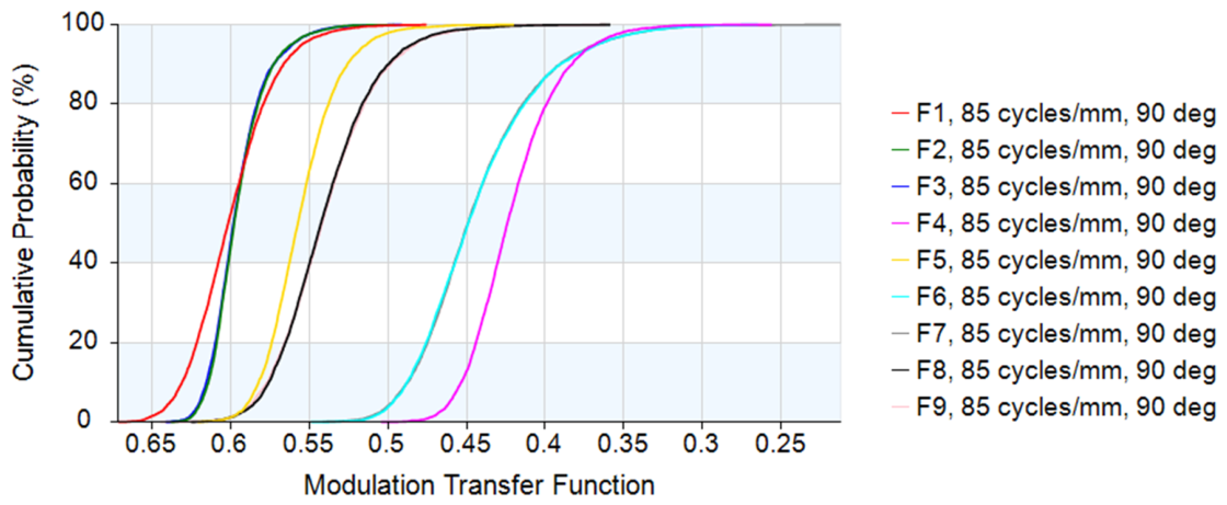
In the assembly process, the final imaging quality can be improved by adjusting the decenter and tilt of the secondary mirror as well as the image plane position. Therefore, the secondary mirror decenter/tilt and the image plane position are selected as the compensators in the tolerance analysis. Two hundred Monte Carlo analyses were performed based on the polychromatic diffraction MTF at 85 lp/mm. The cumulative probability distributions of MTF are shown in Figure 12.
Figure 12.
Cumulative probability distributions of MTF at 85 lp/mm for 200 Monte Carlo trials. Different colors represent different field points (F1–F9).
The results indicate that the MTF is greater than 0.4 at 85 lp/mm with a probability of 80%. The image quality does not change much, which meets the actual production needs.
Further sensitivity analysis shows that the most critical tolerances are the Beta tilt errors (DLB) on the primary (S2) and secondary (S3) mirrors. Cylinder irregularity errors (CYD/CYN on S2) and decenter/tilt terms are the next most sensitive items. These findings highlight that the off-axis mirrors are the dominant sources of tolerance sensitivity in this system. Nevertheless, the compensation mechanism effectively mitigates the impact and ensures overall robustness.
These tolerance analysis results show good consistency with the measured on-axis RMS wavefront error of 0.022λ of the fabricated prototype, further verifying the robustness of the initial structure selected by the proposed node-matching criterion.
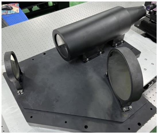
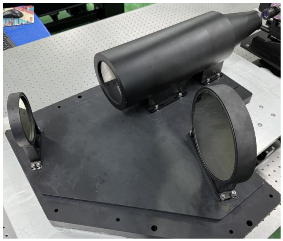
Due to the off-axis reflective design, both primary and secondary mirrors are off-axis conic surfaces, which increases assembly difficulty. To ensure final image quality, hierarchical alignment and stepwise integration techniques were applied. After fabrication and assembly, the reflective primary structure and correction group were verified physically. The manufactured off-axis catadioptric long-focus system is shown in Figure 13.
Figure 13.
Photograph of the fabricated off-axis catadioptric telephoto optical system.
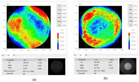
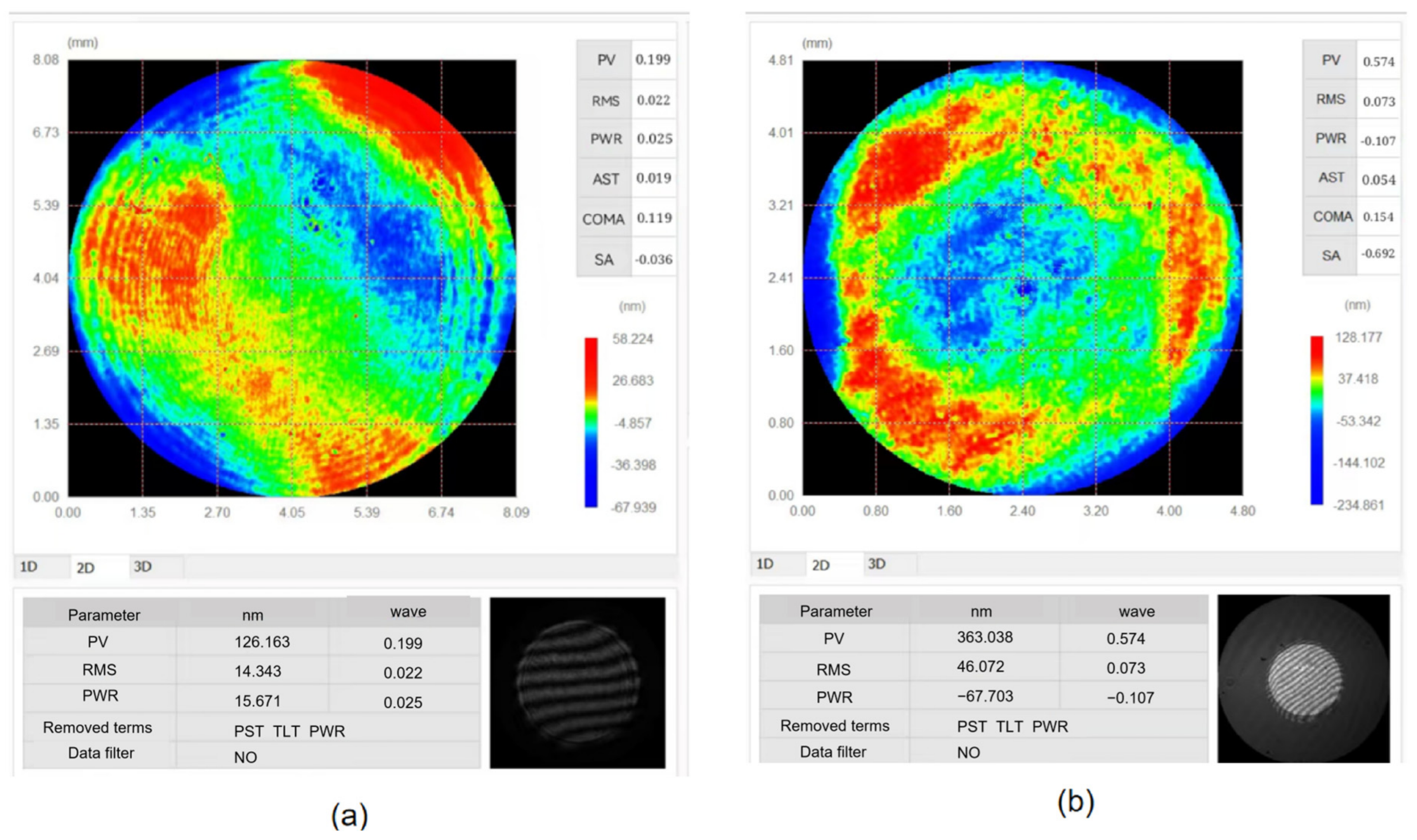
Wavefront measurements were conducted using a laser interferometer. The on-axis interferogram and RMS wavefront error are shown in Figure 14a (RMS = 0.022λ, PV = 0.199λ). The off-axis interferogram at a representative field point is shown in Figure 14b (RMS = 0.073λ, PV = 0.574λ). These measurements confirm that the on-axis imaging quality after fabrication and alignment is excellent, and that the mirror surface figure and system assembly precision meet the design requirements.
Figure 14.
Interferometric measurement result: (a) on-axis wavefront; (b) off-axis wavefront.
5. Conclusions
This study proposes a geometric criterion for initial structure construction in off-axis systems based on vector wave aberration theory: the coma node coincides with the geometric midpoint of the two astigmatism nodes. This criterion ensures balanced major third-order aberration fields, providing an unobscured, stable, and physically interpretable initial structure. Using an off-axis catadioptric long-focus lens as an example, initial structure selection, system optimization, and post-assembly testing were completed. The system achieves a full-field RMS wavefront error below 0.095λ. Tolerance analysis and full-field off-axis measurements further confirm the robustness of the proposed method. The node-matching criterion offers a physically meaningful and engineering-reproducible approach for initial structure selection in off-axis folded systems and is expected to find wide application in future high-performance off-axis optical designs.
Author Contributions
Conceptualization, Y.Z. (Yuchuan Zhao) and Y.Z. (Yiran Zhao); methodology, Y.Z. (Yuchuan Zhao); software, Y.Z. (Yuchuan Zhao); validation, Y.Z. (Yuchuan Zhao), C.M. and Y.Z. (Yiran Zhao); formal analysis, Y.Z. (Yuchuan Zhao); investigation, Y.Z. (Yiran Zhao); resources, C.M.; data curation, H.X.; writing—original draft preparation, Y.Z. (Yuchuan Zhao); writing—review and editing, C.M.; visualization, Y.Z. (Yuchuan Zhao); supervision, Z.S. and N.Y.; project administration, Z.S., N.Y. and C.M.; funding acquisition, H.W., H.Z. and C.M. All authors have read and agreed to the published version of the manuscript.
Funding
This research was funded by the Key Research and Development Program of Shaanxi Province (2025CY-YBXM-076).
Institutional Review Board Statement
Not applicable.
Informed Consent Statement
Not applicable.
Data Availability Statement
Data are available from the authors on request.
Conflicts of Interest
Author Nanxing Yan was employed by the company DFH Satellite Co., Ltd. The remaining authors declare that the research was conducted in the absence of any commercial or financial relationships that could be construed as a potential conflict of interest.
References
- Zhang, X.; Li, J.; Wang, Y. Optical design of multistage confocal off-axis parabolic mirror laser beam expander. Acta Opt. Sin. 2022, 42, 1322001. [Google Scholar]
- Chen, J.; Zhu, L.; Yang, T.; Yang, L.; Xie, H. Design method of an off-axis reflective aperture-divided optical system. Appl. Opt. 2025, 64, 7692–7702. [Google Scholar] [CrossRef] [Scilit] [PubMed]
- Lei, M. Design of an off-axis reflective imaging system using a weighted freeform surface superposition algorithm and the equal optical path condition. Appl. Opt. 2025, 65, 214–221. [Google Scholar] [CrossRef] [Scilit] [PubMed]
- Sun, Y.; Wei, Y. Adaptive design framework for heterogeneous off-axis reflective imaging systems. Appl. Opt. 2025, 65, 3787–3797. [Google Scholar] [CrossRef] [Scilit] [PubMed]
- Xie, Y.; Mao, X.; Li, J.; Wang, F.; Wang, P.; Gao, R.; Li, X.; Ren, S.; Xu, Z.; Dong, R. Optical design and fabrication of an all aluminum unobscured two-mirror freeform imaging telescope. Appl. Opt. 2020, 59, 833–840. [Google Scholar] [CrossRef] [Scilit] [PubMed]
- Mi, Z.; Li, Z.; Zhang, X. Construction of a compact off-axis three-mirror reflective system. Appl. Opt. 2022, 61, 2424–2431. [Google Scholar] [CrossRef] [Scilit] [PubMed]
- Zhao, H.; Gao, L.; Mao, X.; Duan, Y.; Xue, X. Design method of freeform off-axis three-mirror reflective imaging systems. Appl. Opt. 2023, 62, 7852–7859. [Google Scholar] [CrossRef] [Scilit] [PubMed]
- Shi, Y.; Wu, R.; Xing, L.; Dai, Q. Designing an off-axis freeform imaging system with a wide field of view based on an equal optical path surface extension method. Appl. Opt. 2025, 64, 2424–2432. [Google Scholar] [CrossRef] [Scilit] [PubMed]
- Wu, S.; Wang, J.; Miao, L.; Wang, Z.; Fang, F. Freeform off-axis three-mirror anastigmatic system for deep ultraviolet femtosecond laser processing. Appl. Opt. 2025, 64, 9380–9390. [Google Scholar] [CrossRef] [Scilit] [PubMed]
- Yang, T.; Zhu, J.; Hou, W.; Jin, G. Design method of freeform off-axis reflective imaging systems with a direct construction process. Opt. Express 2014, 22, 9193–9205. [Google Scholar] [CrossRef] [Scilit] [PubMed]
- Sun, Y.; Sun, Y.; Chen, X.; Wang, F.; Yan, X.; Zhang, X.; Cheng, T. Free-form off-axis three-mirror optical antenna design with an integrated primary/tertiary-mirror structure. Appl. Opt. 2021, 60, 10133–10139. [Google Scholar] [CrossRef] [Scilit] [PubMed]
- Zhao, G.; Zhu, J. Design method of off-axis reflective freeform zoom optical systems. Opt. Express 2024, 32, 28806–28820. [Google Scholar] [CrossRef] [Scilit] [PubMed]
- Rogers, J.R.; Tachihara, S. Practical tilted mirror systems. Proc. SPIE 1986, 679, 12–16. [Google Scholar]
- Xie, Y.Q. Study on Wide-Field Off-Axis Reflective Systems Based on Vector Aberration Theory. Ph.D. Thesis, University of Chinese Academy of Sciences, Beijing, China, 2022. [Google Scholar]
- Zhang, X.; Li, L.; Huang, L. Design of off-axis four-mirror optical system based on vector aberration theory. Proc. SPIE 2021, 11763, 2565–2572. [Google Scholar]
- Cao, C.; Liao, Z.; Bai, Y.; Fan, Z.-J.; Liao, S. Initial structure design of off-axis reflective optical systems based on vector aberration theory. Acta Phys. Sin. 2019, 68, 120–127. [Google Scholar] [CrossRef] [Scilit]
- Sun, Y.; Wei, X.; Di, X.; Zhao, J. Automatic generation method for long-focal-length unobscured freeform optical systems with small volume. Appl. Opt. 2024, 63, 3702–3711. [Google Scholar] [CrossRef] [Scilit] [PubMed]
- Gray, R.W.; Rolland, J.P. Wavefront aberration function in terms of R. V. Shack’s vector product and Zernike polynomial vectors. J. Opt. Soc. Am. A 2015, 32, 1836–1843. [Google Scholar] [CrossRef] [Scilit] [PubMed]
- Sasián, J. Introduction to Aberrations in Optical Imaging Systems; Cambridge University Press: Cambridge, UK, 2013. [Google Scholar]

Disclaimer/Publisher’s Note: The statements, opinions and data contained in all publications are solely those of the individual author(s) and contributor(s) and not of MDPI and/or the editor(s). MDPI and/or the editor(s) disclaim responsibility for any injury to people or property resulting from any ideas, methods, instructions or products referred to in the content. |
© 2026 by the authors. Licensee MDPI, Basel, Switzerland. This article is an open access article distributed under the terms and conditions of the Creative Commons Attribution (CC BY) license.