


Abstract
Light field displays offer promising autostereoscopic 3D visualization with continuous parallax, full-color reproduction, and natural depth cues. In practice, ray-tracing simulation is often employed to evaluate the effective viewing zone of light field systems. However, the actual viewing zone in conventional light field systems is significantly smaller than the simulated value, severely limited by narrow viewing angles due to crosstalk from adjacent elemental images. This study proposes an isolated microlens array (i-MLA) architecture incorporating a custom directional mesh (DM)—a 3D-printed light-blocking barrier grid with tapered pitch—to physically isolate each lenslet and completely suppress crosstalk. Combined with optimized extended coding pitch for a target viewing distance, ray-tracing simulations and experiments on a 13.3-inch 4K display with a 7 mm and 5.4 mm pitch MLA demonstrate dramatic improvement. The conventional light field system provides only a 3.4° margin, which is below the minimum angular separation required for binocular viewing, whereas the i-MLA system achieves a 7.4° margin—twice that of the conventional system. Compared with conventional systems, the i-MLA architecture does not increase overall volume; it simply replaces the glass gap with a single, simple optical element to achieve a wider viewing angle while preserving the compact form factor.
1. Introduction
Light field displays [1], also known as integral imaging 3D displays, employ microlens arrays (MLA) or pinhole arrays to sample and reconstruct the angular distribution of light rays. The process comprises a capture (pickup) stage, where a lens array records elemental images containing directional parallax information from the 3D scene, and a reconstruction (display) stage, where these images are displayed on a 2D panel and integrated through the lens array to form floating volumetric 3D visuals in space [2,3]. This ray-based approach recreates the original light field, allowing observers to perceive correct perspectives, depth, and parallax naturally.
Key advantages include autostereoscopic viewing, continuous parallax, natural depth perception with accommodation cues to minimize eye fatigue, multi-user support from various angles, and realistic, immersive experiences that closely mimic real-world vision, outperforming binocular stereoscopic methods that suffer from vergence–accommodation conflict [4,5].
Despite these strengths, a major challenge in light field systems is the narrow viewing angle, typically limited to around 10–25 degrees at practical working distances (e.g., 500 mm), due to the small pitch of microlenses, gaps, and field-of-view constraints of individual elemental lenses [6]. This restricts multi-user experiences, causes image flips or crosstalk beyond the viewing zone, and has driven extensive research into solutions such as time-multiplexing and spatial-multiplexing techniques [7,8].
Spatial multiplexing in light field displays expands viewing angles by simultaneously arranging pixels, lenses, and optical elements to deliver multiple perspectives. This approach optimizes elemental image arrays, diffusers, and microlens arrays (MLAs) to fully utilize display resources, reduce crosstalk, and achieve seamless 3D perception. For example, by converting wasted or invalid pixels/light rays into effective parallax information through techniques such as FEP-EIAs, top-hat diffusers with varying-pitch lenses, discrete lenslet arrays, or high-resolution MLA-integrated LCDs, these methods simultaneously increase viewing angle, resolution, or field of view [9,10,11,12].
Time multiplexing enhances viewing angles in light field displays by dynamically switching backlights, lenses, or polarization states in temporal sequences, circumventing spatial resource constraints. Unlike spatial multiplexing, this approach uses rapid switching (e.g., time-division or time-sequential) to stitch viewing zones, reducing crosstalk and improving efficiency, though high refresh rates are needed to avoid flicker. For example, single-eye OVZ to COVZ achieves 81.4° × 47.6° with low crosstalk [13,14]; polarization-switched elemental image arrays with barriers quadruple angle; DTS-BL lens stitching yields 50° view, 4× resolution, 7056 viewpoints [15]. They overcome limits but increase synchronization complexity.
Although spatial multiplexing provides simultaneous multi-perspectives without temporal overhead, and time multiplexing enables dynamic viewing-zone stitching with reduced crosstalk, both significantly increase system complexity and volume. Spatial approaches demand precise alignment and extra optics, causing light-efficiency trade-offs and artifacts; time-multiplexing needs high-refresh-rate displays, eye-tracking, and directional backlights, leading to bulkier hardware, synchronization issues, and higher power use. These hinder scalability for compact devices and of light field displays. Simpler components are needed to widen viewing angles without added thickness or complexity [8,16]. To overcome these challenges, this study proposes an isolated microlens array (i-MLA) architecture incorporating a thin directional mesh. By physically isolating each microlens, the proposed i-MLA system is expected to effectively suppress crosstalk and substantially expand the effective viewing zone while maintaining a compact form factor.
2. Viewing Zone Expansion with Directional Mesh
In light field systems, the viewing angle (VA) represents the angular range within which observers can perceive correct, undistorted 3D images without crosstalk or occlusion artifacts.
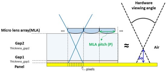
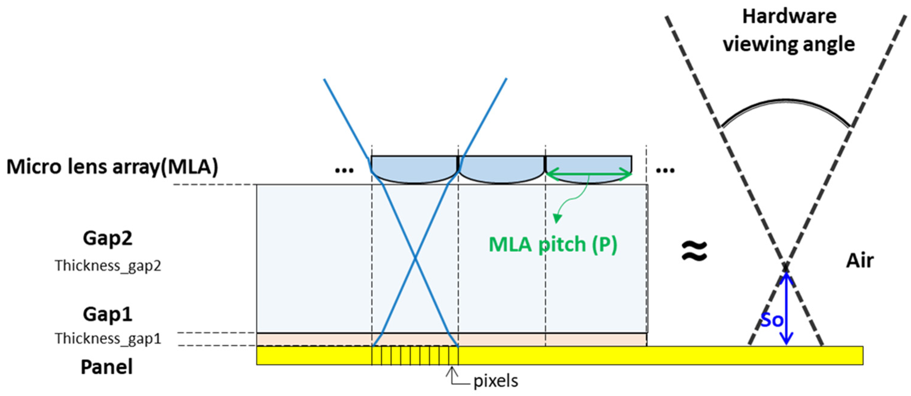
As illustrated in Figure 1, this hardware-limited VA is governed by basic ray geometry. The microlens array (MLA) pitch (P), indicated by the green arrows, defines the center-to-center lateral spacing between adjacent microlenses. The effective object distance (So), shown as the vertical blue arrow, corresponds to the equivalent optical gap from the elemental image plane on the display panel to the MLA.
Figure 1.
Schematic structure of microlens array (MLA) light field system.
Traditionally, the hardware viewing angle is approximated by Formula (1) [17].
where p is the microlens array (MLA) pitch and So is the equivalent object distance (also referred to as the effective gap) between the display panel and the MLA.
To accurately determine the effective object distance for ray geometry, we must account for the optical path length rather than the simple physical thickness. The equivalent object distance So in Formula (2) is derived by summing the optical path lengths of all medium layers between the display panel and the microlens array. Specifically, for each layer, we take its physical thickness divided by its refractive index, and then sum these values across all layers. The equivalent object distance So is obtained by converting the multi-layer structure into a single effective air-equivalent distance:
where T and N represent the thickness and refractive index of each medium layer (cover glass, air gap, glass gap…etc.) respectively. This approach ensures accurate prediction of ray propagation under the paraxial approximation by properly accounting for refraction effects at each interface, following standard optical path length principles commonly used in integral imaging systems.
However, this formula is derived under the paraxial approximation, which assumes that light rays propagate at very small angles relative to the optical axis (typically θ ≪ 1 radian, or <10–15°), allowing simplifications such as sin θ ≈ tan θ ≈ θ and neglecting higher-order aberrations. It also assumes that rays remain close to the optical axis throughout the system, treating the optical behavior linearly as in Gaussian optics [18,19,20]. Consequently, Equation (1) represents an idealized paraxial model that implicitly assumes infinite viewing distance and therefore significantly overestimates the effective VA at finite distances [6]. To rigorously validate these limitations and quantify the actual viewing characteristics, ray-tracing simulations are performed in the following sections.
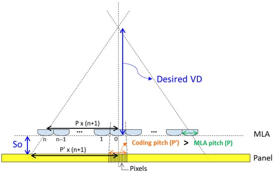
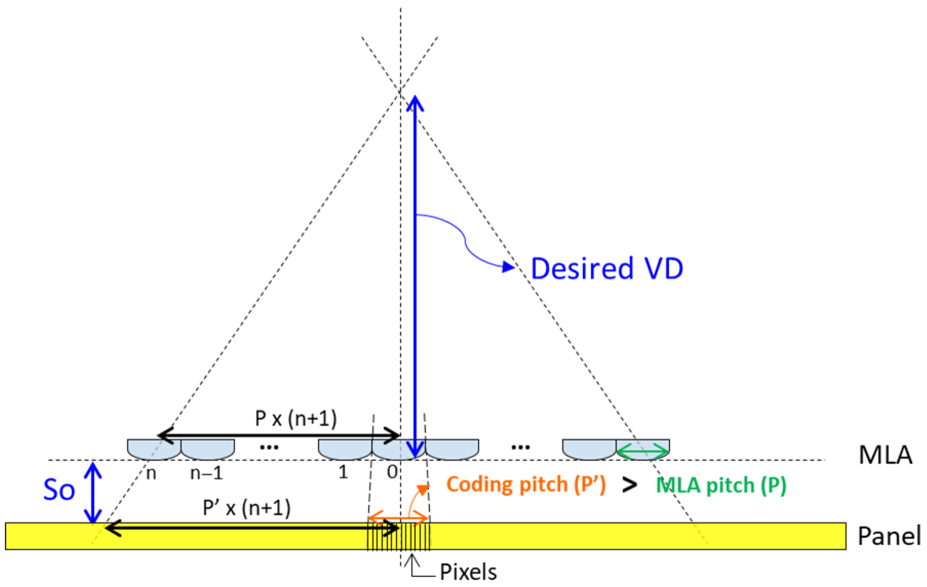
Furthermore, in light field systems, to enable observers to view clear stereoscopic 3D images at a specific working distance, the system typically extends the coding pitch (also known as the elemental image pitch) in the capture-stage algorithm while keeping the central lens aligned with the center of the display panel in the horizontal direction. As shown in Figure 2 [6,21], the gap between the microlens array and the display panel is represented by the equivalent air gap, which serves as the effective object distance. The distance from the microlens to the human eye corresponds to the desired viewing distance (VD). Based on the principle of similar triangles, the relationship in Equation (3) for the extended coding pitch is derived.
Figure 2.
Schematic of extended coding pitch P’ determined by equivalent object distance So and desired viewing distance through similar triangles in a light field display system.
As a result, the centers of the elemental images progressively deviate from the corresponding lens centers, with the maximum separation occurring at the edges of the screen. This intentional offset allows the light cone projected by each elemental lens to converge properly at the designated viewing distance, ensuring that the reconstructed 3D image falls within the observer’s comfortable VA [22].
In the simulation phase, a 13.3-inch 4K display panel (3840 × 2160 pixels) was overlaid with a square-grid microlens array (MLA) of pitch P = 7 mm and 5.4 mm (7 × 9 microlenses in total) and focal length 41.9 mm. Using the conventional hardware VA formula under paraxial approximation at infinite VD, the theoretical VA was 7.4°, an idealized limit assuming no crosstalk or off-axis effects.
To optimize 3D perception at a practical desktop VD of 500 mm, the coding pitch was extended beyond P. Equation (2) yields P’x = 7.752 mm and P’y = 5.981 mm, tilting angular information to align light cones with the target VD while preserving central alignment. This extension causes significant discrepancy between hardware VA and actual performance, necessitating detailed ray-tracing simulations to accurately quantify the effective viewing zone.
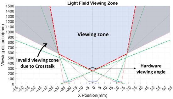
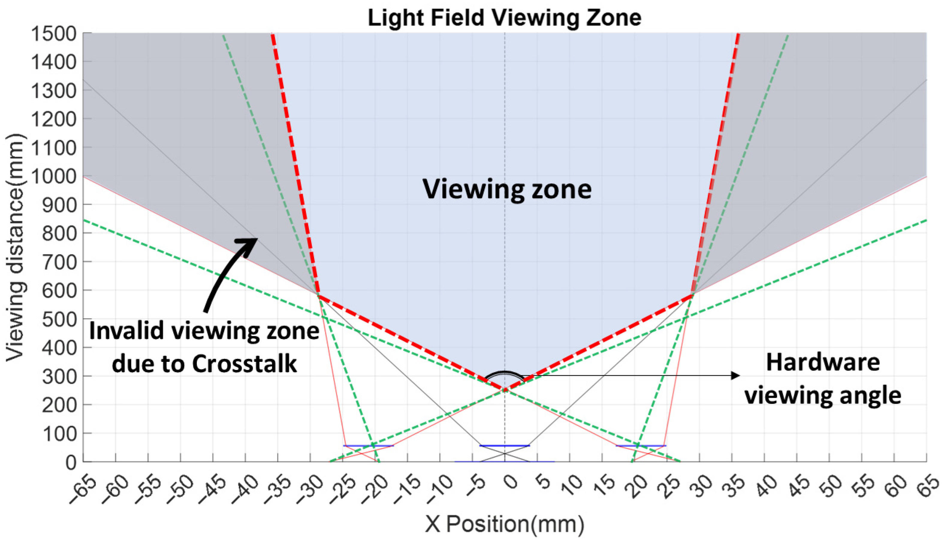
As shown in Figure 3, which presents a side view along the optical axis and defines the viewing distance measured from the system top, the hardware-limited VA is bounded by the outermost emergent rays from the two edge lenslets along the panel’s long axis (X-direction). The green dashed lines depict the hardware VA calculated under paraxial approximation. In this model, the virtual rays from the two outermost lenslets intersect at a height of approximately 500 mm, forming the theoretical VA cone. However, Equation (1) does not account for the severe impact of crosstalk in practical scenarios.
Figure 3.
System viewing zone analysis for a 7-microlens array of a conventional light field display, showing the viewing zone confined within the blue diamond-shaped region.
To more accurately evaluate the system’s real viewing characteristics, ray-tracing analysis was performed using MATLAB version R2024b [23]. This method traces light-ray propagation from the display panel, through intermediate media (e.g., cover glass and air gaps), through the microlens array (MLA), fully accounting for realistic optical interface interactions often neglected in analytical models. Rays from the two outermost lenslets (the third from the left and right edges, indicated by red solid lines) and the central lenslet (indicated by black solid lines) were simulated. Their intersections form a blue diamond-shaped region enclosed by red dashed lines, termed the viewing zone, where observers perceive correct, undistorted 3D images without crosstalk. Outside this zone—for example, lateral shifts exceeding ±30 mm at VD = 600 mm—severe crosstalk occurs, causing flipped, duplicated, or ghosted images. Simulations clearly show the actual VA is significantly smaller than the paraxial-predicted hardware VA.
By analyzing the geometry of the blue diamond region bounded by the red dashed lines relative to the panel center, the actual system VA can be quantified across various viewing distances. The results indicate that the effective VA offers virtually no usable margin at short viewing distances (VD) or large angles due to severe crosstalk. A usable viewing margin emerges beyond VD = 500 mm, progressively increasing to a peak of approximately 5.5° at VD = 600 mm, then gradually decreasing thereafter. These simulations reveal that, even with extended coding pitch (P’), the maximum VA at VD = 600 mm is only approximately 5.5° overall—roughly three-quarters (75%) of the hardware VA predicted by the paraxial approximation—thus highlighting the limitations of paraxial models in practical light field system implementations.
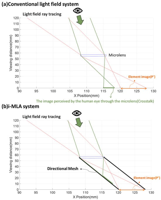
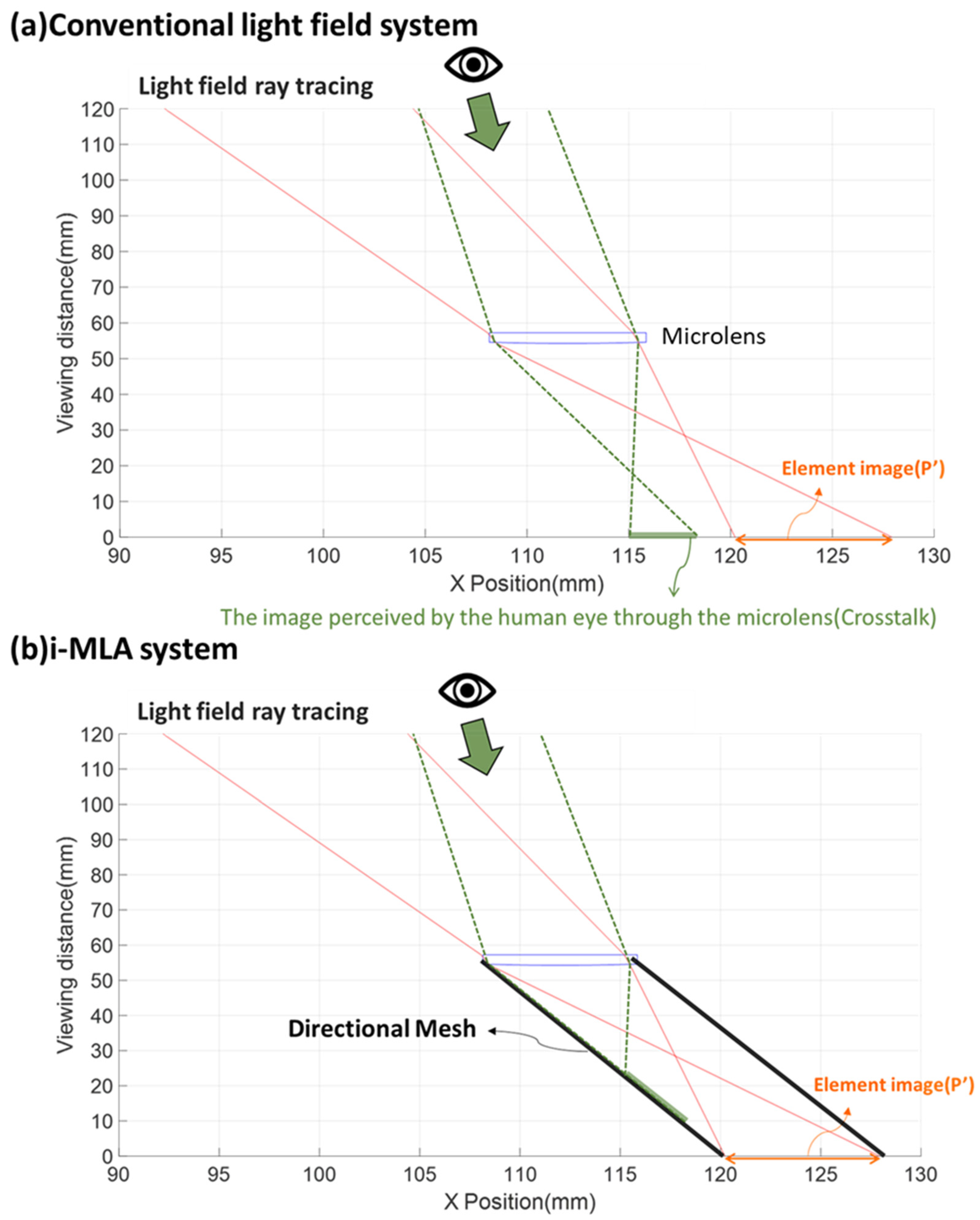
Crosstalk is the primary factor responsible for the significant discrepancy between the actual system viewing angle and the paraxial approximation. As shown in Figure 4a, in a conventional light field display system, the red solid lines represent the ray-tracing paths originating from the elemental image and refracted through the corresponding microlens. The angular information provided by each microlens is defined by these rays, forming a specific viewing cone. When the observer’s eye moves outside the blue diamond-shaped viewing zone, the line of sight (green dashed lines) passes through several microlenses. Ray tracing reveals that the imaging point falls outside the current microlens’s elemental image and into a neighboring one. Consequently, the eye simultaneously receives image information from unintended neighboring views, resulting in severe crosstalk. This phenomenon degrades the 3D image quality, causing ghosting or double images.
Figure 4.
(a) In a conventional light field display, when the eye moves outside the viewing zone, ray tracing (green dashed lines) shows rays reaching beyond the current elemental image, resulting in crosstalk. (b) In the i-MLA system, the Directional Mesh blocks off-axis rays from reaching the eye, effectively eliminating crosstalk.
In contrast, to maximize the viewing zone and suppress crosstalk as effectively as possible, the proposed system incorporates a directional mesh, as illustrated in Figure 4b. By fully enclosing each lenslet and its elemental image with opaque, low-reflection material, the isolated lenslet effectively restricts light passage and prevents unintended ray leakage. When the eye is at the same position, ray tracing shows that the directional mesh blocks unwanted rays, successfully preventing light from unintended views from reaching the observer and significantly eliminating crosstalk.
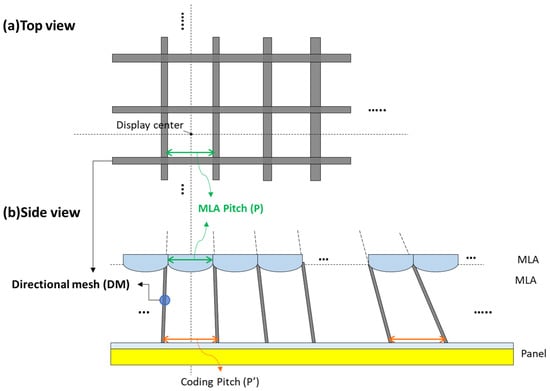
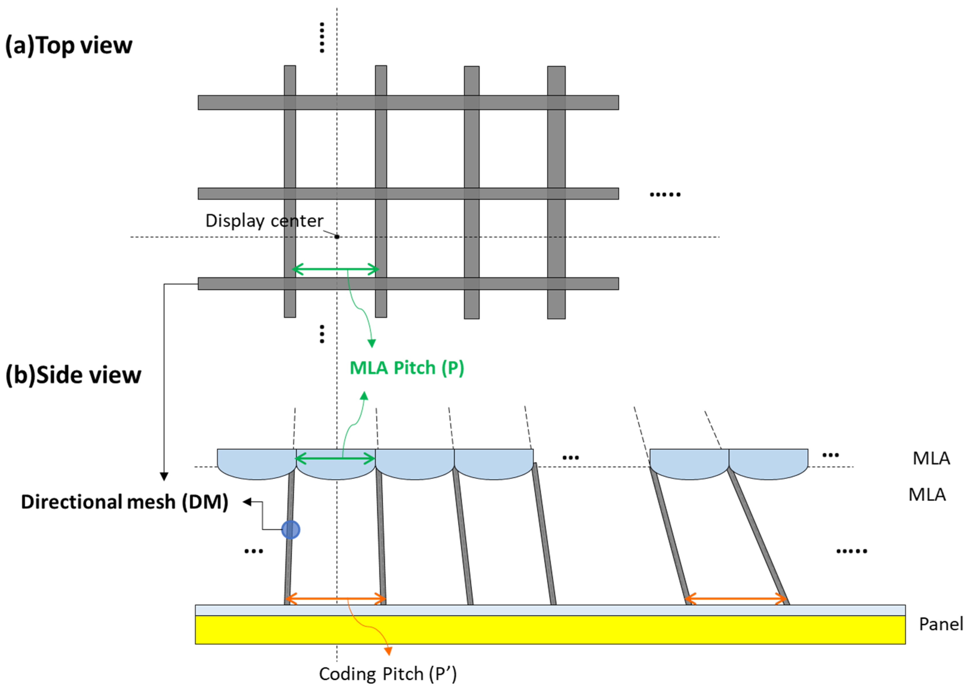
As illustrated in Figure 5, by physically isolating each lenslet with light-blocking barriers, every elemental image is strictly coupled to only one corresponding lenslet. This architecture is referred to as the isolated microlens array (i-MLA) system. The directional mesh completely eliminates crosstalk artifacts and substantially expands the usable viewing margin for human observers. Consequently, viewers perceive only the intended primary image from each lenslet, with virtually no interference from first-order or higher-order crosstalk images.
Figure 5.
Directional mesh structure in the i-MLA system showing progressive barrier tilt. (a) Top view, (b) side view.
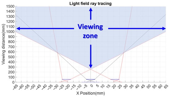
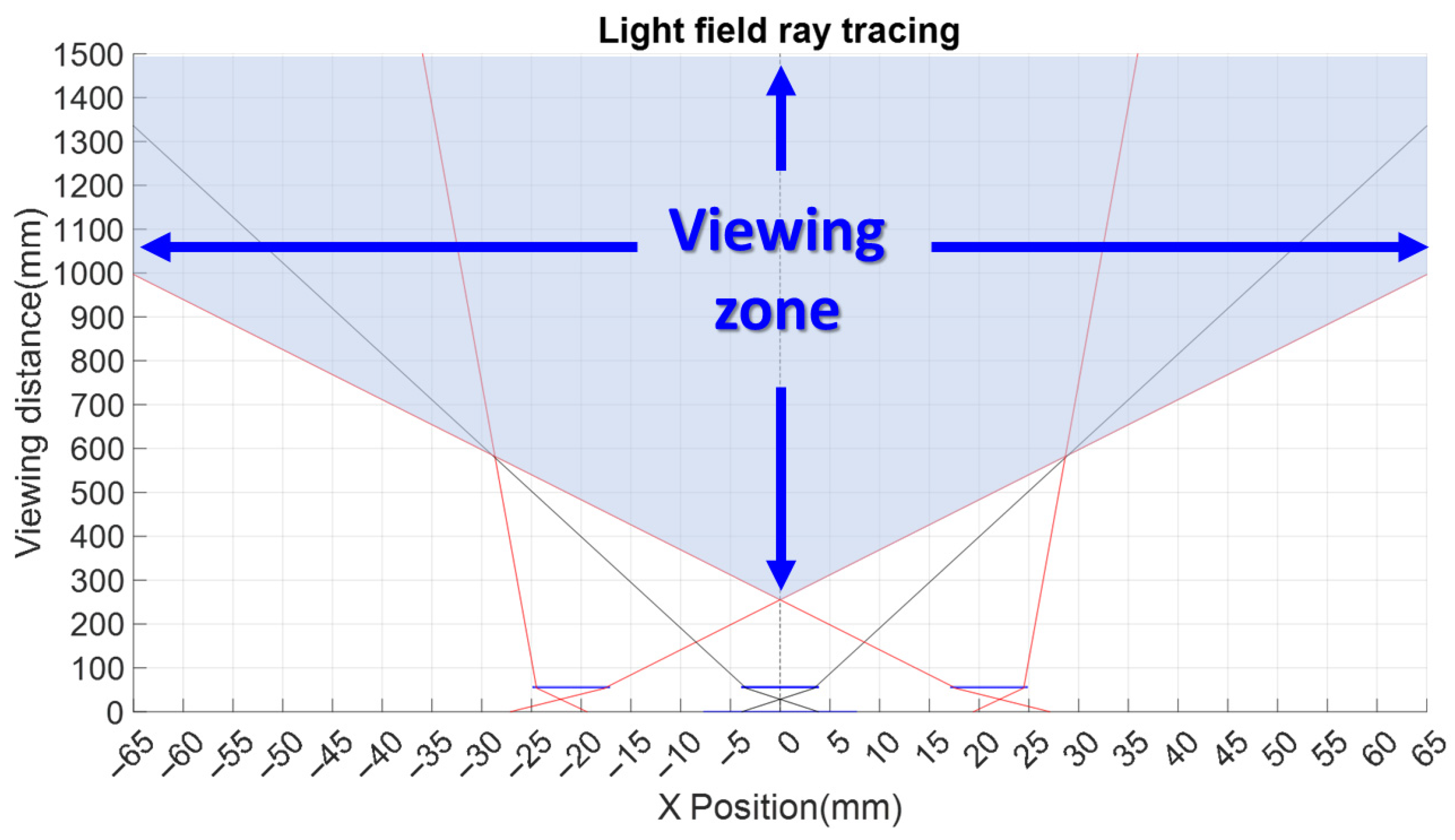
After incorporation of the directional mesh, the original diamond-shaped region bounded by the red solid lines is dramatically expanded, effectively covering nearly the entire usable viewing volume (i.e., almost all viewing space beyond VD ≈ 300 mm), as represented by the full blue area in Figure 6.
Figure 6.
System viewing zone analysis of i-MLA system, showing blue region is the viewing zone for crosstalk-free 3D viewing.
3. Experiment and Results
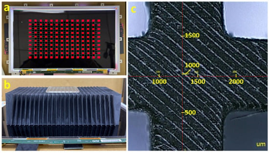
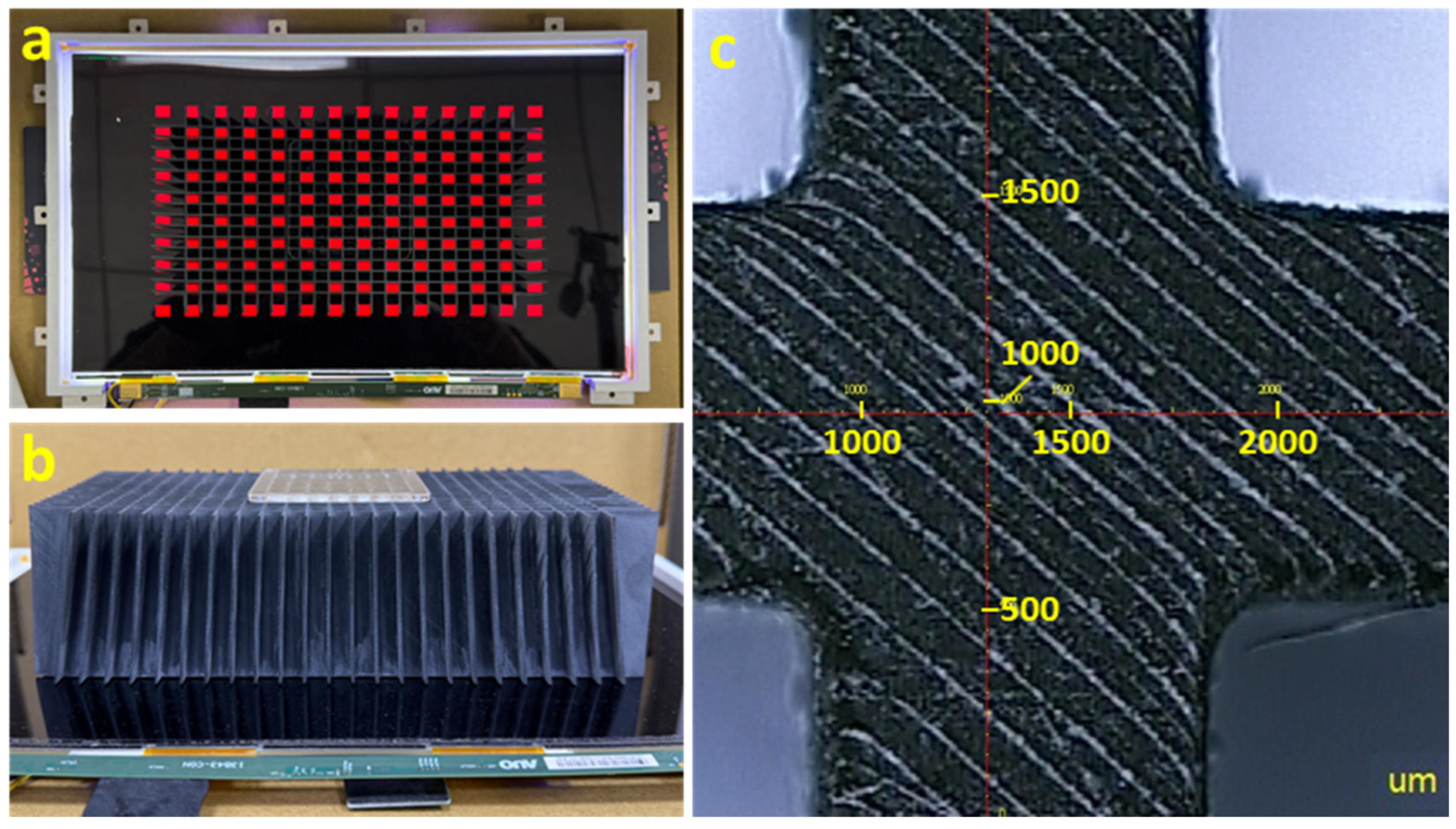
Figure 7a,b illustrate the experimental setup of the proposed autostereoscopic floating 3D light field i-MLA system, using a compact layered architecture for slim form factor. The bottom layer is a high-resolution display panel (e.g., 13.3-inch 4K, 3840 × 2160 pixels). The top layer is a commercially available MLA (#63-231, Edmund Optics) in a 7 × 9 rectangular grid (pitch 7 mm × 5.4 mm, focal length 41.9 mm, active area ≈49 mm × 48.6 mm) to reconstruct the light field for floating 3D images.
Figure 7.
(a) Top view of alignment pattern and (b) side view of the experimental i-MLA system. (c) Microscopic view of the Directional Mesh structure.
The MLA is inverted (convex surfaces facing downward) to enhance crosstalk suppression and alignment tolerance. Unlike conventional convex-up configurations, where rays leak slightly into adjacent lenses after the DM, the inverted design enables immediate interaction with the curved surface, preventing leakage. The downward convex surfaces nest perfectly into the DM barriers, improving mechanical stability, alignment ease, and manufacturing repeatability for high-volume production.
An air gap between the panel and MLA contains a directional mesh of thin, opaque black grid barriers that physically isolate each lenslet and minimize stray reflections. The DM’s upper surface matches the MLA pitch (7 mm × 5.4 mm), while the lower surface has a larger pitch (7.752 mm × 5.981 mm) to accommodate the extended elemental image arrangement. This confines each elemental image strictly to its microlens, completely eliminating crosstalk.
The entire structure maintains a flat, slim profile, with the air gap and directional mesh carefully optimized for optical performance, mechanical simplicity, and manufacturability. By addressing key limitations of conventional light field systems—particularly crosstalk and narrow VA—this design significantly expands the effective VA, positioning it as one of the most promising approaches for a practical, commercially viable ultra-wide-angle autostereoscopic floating 3D display.
Considering cost-effectiveness and ease of fabrication, 3D printing based on photopolymerization (light-curing) technology was selected as the primary manufacturing method for the directional mesh. This approach involves slicing the 3D model into thin layers and sequentially curing photosensitive resin with UV light, commonly using high-resolution techniques such as Stereolithography (SLA), Digital Light Processing (DLP), or Liquid Crystal Display (LCD) masking. Thanks to ultra-high-resolution monochrome LCD screens (8K, 12K, or higher), which provide extremely high pixel density, these systems enable precise control of UV curing in microscopic regions, far surpassing the surface roughness of traditional FDM or low-end resin printers.
In this layer-by-layer process, a UV light source illuminates the resin through a patterned mask or projector, solidifying each layer precisely before the build platform rises to allow the addition of the next layer of uncured resin. This method achieves high-resolution outputs capable of intricate details at the micron scale. Furthermore, black photopolymer resin was employed for its near-zero transmittance and low visible-light total reflectance (approximately 4–10%), which effectively absorbs stray light to block crosstalk and minimizes ghosting artifacts arising from internal reflections.
To ensure structural robustness, the DM was printed with a height of 60 mm and barrier thickness of 1 mm. The finished product, as shown in Figure 7b, exhibits progressively increasing barrier tilt from the center outward due to the mismatched upper and lower pitches. This design imparts a directional structure to the DM, focusing the projected images toward the predefined viewing distance (VD) of 500 mm, thereby optimizing the light field reconstruction for wide VA without compromising compactness.
The fabricated directional mesh was characterized using 2.5D optical profilometry to assess surface topography, barrier height uniformity, and pitch accuracy, as presented in the corresponding Figure 7c. The magnified 2.5D measurement image shows barrier walls with a uniform dark appearance, sharp and well-defined edges, with only minor residual island-like features present at the wall corners. Key dimensional parameters extracted from the measurement are summarized in the accompanying table: barrier thickness ≈ 0.942 mm; upper pitch (designed to match the MLA) ≈ 6.966 mm in one direction and ≈5.369 mm in the orthogonal direction; lower extended pitch ≈ 7.778 mm and ≈ 6.022 mm. All measured pitch values deviate from the target design (upper: 7 mm × 5.4 mm; lower: 7.752 mm × 5.981 mm) by less than 1%, demonstrating outstanding fabrication accuracy and reproducibility. These results confirm the successful realization of the intended trapezoidal barrier profile and progressive pitch gradient, thereby ensuring robust light isolation and directional performance in the isolated microlens array (i-MLA) system.
Before conducting the experiments, previous ray-tracing simulations (as shown in Figure 3) evaluate the system margin. Due to the limited 7 × 9 microlens array (MLA), the simulation covers only a small ~49 mm × 49 mm portion involving seven lenslets. Under the same extended coding pitch, at a viewing distance (VD) of 600 mm, both the conventional light field system and the proposed i-MLA system show comparable horizontal margins of approximately ±30 mm. However, at VD = 1000 mm, crosstalk emerges in the conventional system beyond ±32 mm horizontal displacement, limiting the effective margin, whereas the i-MLA system—due to the directional mesh completely eliminating crosstalk—extends the horizontal margin to ±65 mm, nearly double that of the conventional system. These simulation results will be validated through subsequent experimental measurements.
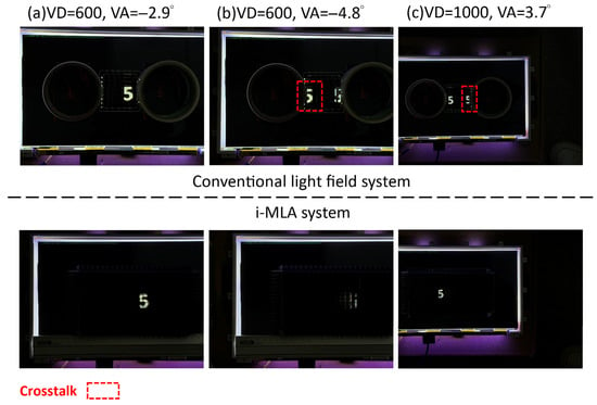
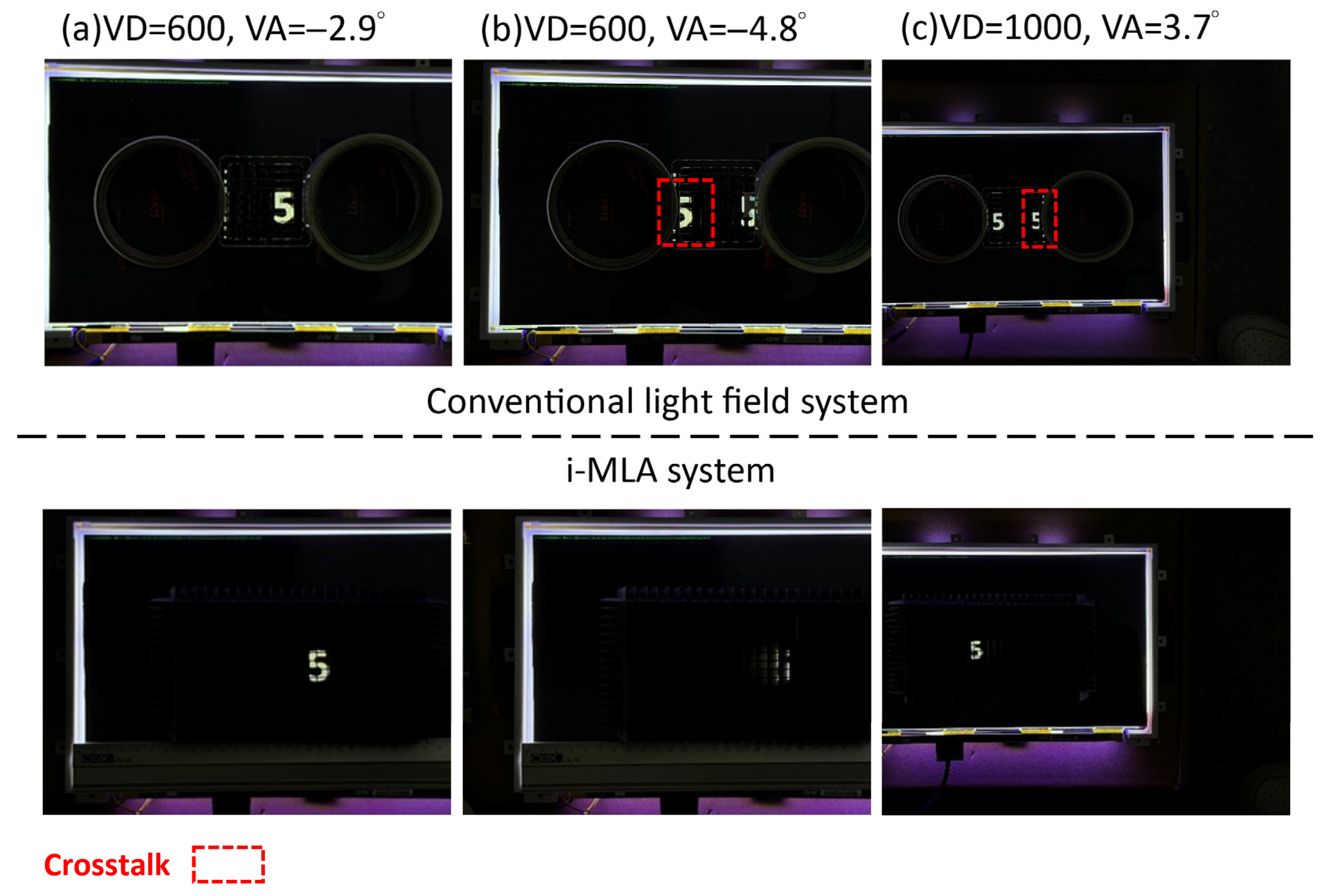
After full assembly, the viewing margin was compared between the conventional light field system (extended coding pitch without directional mesh, DM)—shown in the top row of Figure 8—and the proposed i-MLA system (with DM)—shown in the bottom row of Figure 8—at a viewing distance of 600 mm.
Figure 8.
Experimental viewing margin comparison between conventional light field (top row) and i-MLA system (bottom row) at different viewing distances (VD). (a) At VD = 600 mm, both systems show identical margin. (b) At VA = −4.8°, conventional shows severe crosstalk; i-MLA eliminates it. (c) At VD = 1000 mm, i-MLA expands to ±65 mm (~7.4°), twice conventional.
As shown in Figure 8a, both configurations support a lateral movement of approximately ±30 mm (±2.9°) from the screen center (total usable range 60 mm, corresponding to ~5.8°). Within this range, only the correct primary image of the digit “5” is observed. The measured result aligns closely with prior ray-tracing simulations.
Beyond ±30 mm, the conventional system exhibits severe crosstalk (Figure 8b top row): at −50 mm (−4.8°), crosstalk appears on the left side while the primary image begins to lose information but remains partially visible on the right. In contrast, as shown in Figure 8a bottom row, the i-MLA system with directional mesh shows symmetric fade-in/fade-out behavior near the edges, fading cleanly beyond ±30 mm without any residual crosstalk or ghosting. Thus, the usable lateral range remains 60 mm (±30 mm), equivalent to that of the conventional light field system, but the viewing experience is significantly cleaner and free of artifacts.
At a larger viewing distance of 1000 mm, the difference becomes more pronounced. In the conventional system, only within the range of −30 mm to +30 mm does the reconstructed image consist solely of the primary (intended) image, corresponding to a total usable viewing margin of approximately 3.4° at VD = 1000 mm. Beyond this range (Figure 8c top row), at offsets around ±65 mm (±3.7°), the primary image and first-order crosstalk image fully overlap with high visibility, resulting in distorted and unusable views.
In the i-MLA system with directional mesh (Figure 8 bottom row), crosstalk is completely suppressed even at large offsets. The correct “5” image remains clear and complete from −65 mm to +65 mm (total usable range 130 mm, ~7.4°), while the screen simply turns black outside this region with no ghosting, flipping, or leakage observed. This represents more than double the effective viewing margin of the conventional system.
These experimental results align closely with the simulations and clearly demonstrate that the directional mesh effectively suppresses crosstalk, thereby substantially expanding the practical viewing zone without added system volume or manufacturing complexity.
4. Discussions
The directional mesh serves as a critical component in this work. Due to budget constraints, a 3D printing process was adopted for its fabrication. However, the design complexity—arising from the progressive pitch gradient and angled barrier walls—imposed significant challenges. As a result, the barrier thickness could not be reduced below 1 mm.
This limitation stemmed primarily from three factors inherent to the 3D printing system and materials used: the minimum achievable feature size imposed by the machine resolution, the mechanical and thermal properties of the printable materials (which affect structural integrity and warpage during curing), and the practical difficulties encountered during post-print removal and demolding of the delicate barrier structures.
These design constraints ensured printability and mechanical stability but compromised optical performance, resulting in a noticeable decrease in light efficiency and a visible grid-like moiré pattern in the experimental prototype.
To evaluate the actual impact on brightness, we measured the luminance of the display with a full-white pattern using a Konica Minolta CA-310 color analyzer. The measurement probe was placed 1 cm above the system. Without the directional mesh, the luminance was 365 nits. After incorporating the 1 mm thick DM, the luminance decreased to 146 nits, corresponding to approximately 40% of the original brightness.
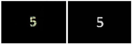
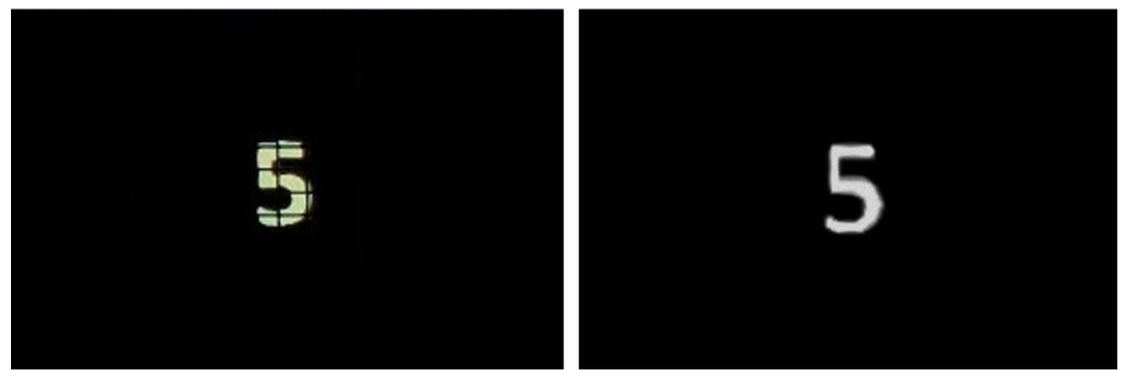
As shown in the magnified view of the left image in Figure 9, the relatively thick barriers produce perceptible grating artifacts in the reconstructed image. In contrast, simulations used a reduced barrier thickness of 50 μm, which falls below the human eye’s angular resolution limit at typical viewing distances, making the grid imperceptible. Consequently, the simulated results (right image in Figure 9) yield a clean reconstructed image free of observable moiré or grating effects.
Figure 9.
Experimental results (left figure) and simulation results (right figure) of the i-MLA system.
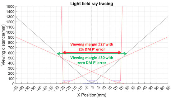
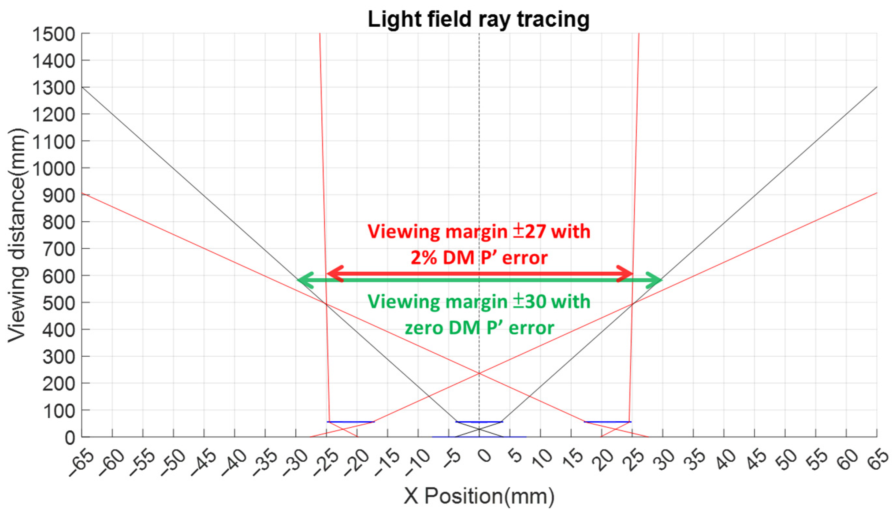
To evaluate the impact of fabrication tolerance on the directional mesh (DM), we performed additional analysis regarding pitch variation. As illustrated in Figure 10, where the innermost red lines indicate the boundaries, assuming a fabrication tolerance of 2% (i.e., the bottom pitch of the DM increases to 7.7523 × 1.02 = 7.9073 mm), the allowable movement range at a viewing distance (VD) of 600 mm decreases slightly to ±27 mm. Beyond this range, crosstalk occurs due to misalignment between the barriers and the elemental images, causing the effective viewing angle to reduce to 4.8°.
Figure 10.
Effect of 2% DM pitch error on the viewing margin at VD = 600 mm, where the allowable range decreases from ±30 mm (zero error) to ±27 mm (with 2% error).
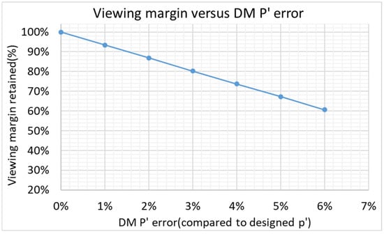
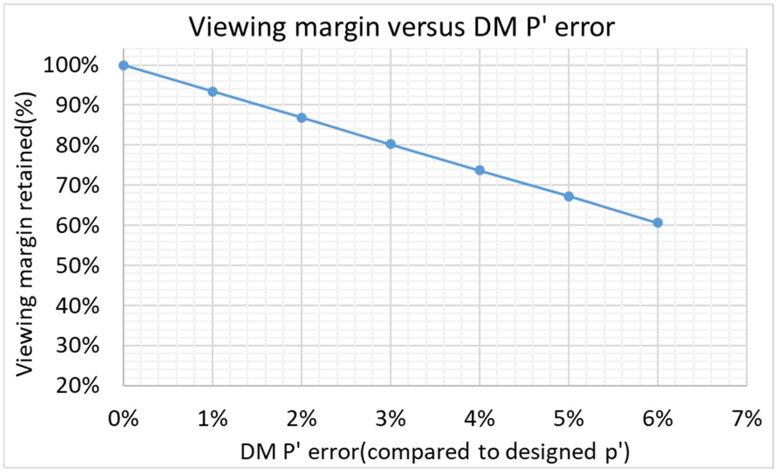
To provide a more comprehensive understanding, we further plotted the relationship between pitch error (ranging from 1% to 6%) and the resulting viewing margin, as shown in Figure 11. These results demonstrate that the current fabrication accuracy (<1% deviation) retains more than 93% of the viewing margin and remains well within an acceptable range that does not significantly degrade the 3D viewing experience.
Figure 11.
Effect of DM pitch error on viewing margin. The retained viewing margin decreases from 100% (0% error) to 60% (6% error).
Furthermore, regarding the potential influence of the directional mesh (DM) on the depth of field, the following clarification is provided. As indicated in Equation (12-5) of the second reference cited in our manuscript [2], the depth of field in light field systems is inversely proportional to the lens pitch and spatial resolution. Since the spatial resolution, according to Equation (12-2) in [2], is not affected by the incorporation of the directional mesh (DM), the resolution term is not considered here. However, the introduction of the DM effectively reduces the effective pitch. As a result, the depth of field is increased. For example, in the current design, the ratio of the effective pitch (lens pitch minus DM barrier thickness) to the lens pitch after incorporating the DM is 6:7, leading to a 16% increase in depth of field. If a more advanced fabrication process is used in the future to further reduce the barrier thickness (approaching the simulated ideal thickness 50 μm), the effective pitch to lens pitch ratio would become 6.95:7, resulting in only a 0.7% increase in depth of field, which is negligible.
In the future, advanced fabrication techniques could reduce barrier thickness well below 1 mm. Promising approaches include femtosecond laser micromachining for high-precision ablation and nanoimprint lithography (NIL), both providing excellent resolution, improved aspect ratios, and compatibility with thinner, highly opaque materials. These methods would allow finer barrier structures while preserving mechanical stability and optical performance, potentially further increasing the viewing margin and overall system efficiency.
5. Conclusions
In conclusion, this study presents an isolated microlens array (i-MLA) integrated with a thin directional mesh that completely eliminates crosstalk in light field displays, dramatically expanding the viewing zone without increasing system thickness. Ray-tracing and experimental results consistently show that the actual VA significantly exceeds the optimistic paraxial prediction, achieving an effective margin of 7.4° (more than double the conventional 3.4°) through optimized extended coding pitch and 3D-printed tapered barriers.
Unlike bulky spatial/time-multiplexing approaches, the i-MLA architecture replaces the conventional air gap with a simple DM component, offering superior scalability for compact, portable 3D displays. Future refinement of finer DM structures could enable even larger coding pitches and broader viewing zones. Overall, this design offers a practical, volume-efficient route toward commercially viable glasses-free light field displays.
Author Contributions
Conceptualization, H.Y.H.; methodology, H.Y.H.; software, H.Y.H.; validation, H.Y.H.; formal analysis, H.Y.H.; writing—original draft preparation, H.Y.H.; writing—review and editing, H.Y.H. and C.-H.C. All authors have read and agreed to the published version of the manuscript.
Funding
This work was supported by Lixel.
Institutional Review Board Statement
Not applicable.
Informed Consent Statement
Not applicable.
Data Availability Statement
Data will be made available on request.
Conflicts of Interest
The authors declare no conflicts of interest.
References
- Holliman, N. 3D Display Systems. 2003. Available online: https://www.researchgate.net/publication/2831403_3D_Display_Systems (accessed on 11 March 2026).
- Lee, B.; Park, J.-H.; Min, S.-W. Three-dimensional display and information processing based on integral imaging. In Digital Holography and Three-Dimensional Display; Poon, T.-C., Ed.; Springer: Berlin/Heidelberg, Germany, 2006; pp. 333–378. [Google Scholar]
- Liu, Z.-S.; Li, D.-H.; Deng, H. Integral Imaging-Based Light Field Display System With Optimum Voxel Space. IEEE Photon. J. 2024, 16, 5200207. [Google Scholar] [CrossRef] [Scilit]
- Geng, J. Three-dimensional display technologies. Adv. Opt. Photon. 2013, 5, 456. [Google Scholar] [CrossRef] [Scilit]
- Kara, P.A.; Simon, A. The Good News, the Bad News, and the Ugly Truth: A Review on the 3D Interaction of Light Field Displays. Multimodal Technol. Interact. 2023, 7, 45. [Google Scholar] [CrossRef] [Scilit]
- Liu, Z.; Li, D.; Deng, H. Wide-Viewing-Angle Integral Imaging System with Full-Effective-Pixels Elemental Image Array. Micromachines 2023, 14, 225. [Google Scholar] [CrossRef] [Scilit] [PubMed]
- Hua, J.; Hua, E.; Zhou, F.; Shi, J.; Wang, C.; Duan, H.; Hu, Y.; Qiao, W.; Chen, L. Foveated glasses-free 3D display with ultrawide field of view via a large-scale 2D-metagrating complex. Light Sci. Appl. 2021, 10, 213. [Google Scholar] [CrossRef] [Scilit] [PubMed]
- Hua, J.; Qiao, W.; Chen, L. Recent Advances in Planar Optics-Based Glasses-Free 3D Displays. Front. Nanotechnol. 2022, 4, 829011. [Google Scholar] [CrossRef] [Scilit]
- Chang, C.-Y.; Lin, H.-Y. 36-3: Design and Analysis of Brightness enhancement Integral Imaging Based 3D Light-Field Normal Display and Optical See-Through Light-Field Display by Discrete Lenslet Array. In Digest of Technical Papers—SID International Symposium; John Wiley and Sons Inc.: Hoboken, NJ, USA, 2023; Volume 54, pp. 522–525. [Google Scholar] [CrossRef] [Scilit]
- Le Zhang, H.; Liu, Y.J.; Ma, X.L.; Xing, Y.; Wang, Q.H. Integral Imaging 3D Display Based on Top-hat Diffusing Screen. In Digest of Technical Papers—SID International Symposium; John Wiley and Sons Inc.: Hoboken, NJ, USA, 2023; Volume 54, pp. 1633–1636. [Google Scholar]
- Liu, Z.; Li, D.; Deng, H. P-8.3: Integral Imaging Display System with Enhanced Viewing Angle. In Digest of Technical Papers—SID International Symposium; John Wiley and Sons Inc.: Hoboken, NJ, USA, 2023; Volume 54, pp. 755–759. [Google Scholar] [CrossRef] [Scilit]
- Wu, Y.-H.; Chang, C.-C.; Tsou, Y.-S.; Lo, Y.-C.; Tsai, C.-H.; Lu, C.-H.; Yang, C.-L.; Chuang, F.-M. Enhancing virtual reality with high-resolution light field liquid crystal display technology. J. Opt. Microsyst. 2023, 3, 041202. [Google Scholar] [CrossRef] [Scilit]
- Okaichi, N.; Sasaki, H.; Kano, M.; Arai, J.; Kawakita, M.; Naemura, T. Integral three-dimensional display system with wide viewing zone and depth range using time-division display and eye-tracking technology. Opt. Eng. 2022, 61, 013103. [Google Scholar] [CrossRef] [Scilit]
- Yuan, Y.; Wu, X.; Wang, X.; Zhang, Y. Wide-viewing integral imaging system using polarizers and light barriers array. J. Eur. Opt. Soc. Publ. 2017, 13, 25. [Google Scholar] [CrossRef] [Scilit]
- Yang, L.; Sang, X.; Yu, X.; Yan, B.; Wang, K.; Yu, C. Viewing-angle and viewing-resolution enhanced integral imaging based on time-multiplexed lens stitching. Opt. Express 2019, 27, 15679–15692. [Google Scholar] [CrossRef] [Scilit] [PubMed]
- Xiong, J.; Hsiang, E.-L.; He, Z.; Zhan, T.; Wu, S.-T. Augmented reality and virtual reality displays: Emerging technologies and future perspectives. Light Sci. Appl. 2021, 10, 216. [Google Scholar] [CrossRef] [Scilit]
- Martínez-Corral, M.; Javidi, B. Fundamentals of 3D imaging and displays: A tutorial on integral imaging, light-field, and plenoptic systems. Adv. Opt. Photon. 2018, 10, 512–566. [Google Scholar] [CrossRef] [Scilit]
- Baasantseren, G.; Park, J.-H.; Kwon, K.-C.; Kim, N. Viewing angle enhanced integral imaging display using two elemental image masks. Opt. Express 2009, 17, 14405–14417. [Google Scholar] [CrossRef] [Scilit] [PubMed]
- Yao, C.; Cheng, D.; Wang, Y. Matrix optics representation and imaging analysis of a light-field near-eye display. Opt. Express 2020, 28, 39976–39997. [Google Scholar] [CrossRef] [Scilit] [PubMed]
- Mignard-Debise, L. Tools for the Paraxial Optical Design of Light Field Imaging Systems. Doctoral Dissertation, Université de Bordeaux, Bordeaux, France, 2018. [Google Scholar]
- Deng, H.; Lv, G.; Deng, H.; Liu, Z. Viewing-Angle-Enhanced and Dual-View Compatible Integral Imaging 3D Display Based on a Dual Pinhole Array. Micromachines 2024, 15, 381. [Google Scholar] [CrossRef] [Scilit] [PubMed]
- Xing, Y.; Lin, X.-Y.; Zhang, L.-B.; Xia, Y.-P.; Zhang, H.-L.; Cui, H.-Y.; Li, S.; Wang, T.-Y.; Ren, H.; Wang, D.; et al. Integral imaging-based tabletop light field 3D display with large viewing angle. Opto-Electron. Adv. 2023, 6, 220178. [Google Scholar] [CrossRef] [Scilit]
- Hou, H.-Y.; Chen, C.-H. 70-3: Wide Field of View Flat Panel Light Field Display. In SID Symposium Digest of Technical Papers; John Wiley and Sons Inc.: Hoboken, NJ, USA, 2024. [Google Scholar]
Disclaimer/Publisher’s Note: The statements, opinions and data contained in all publications are solely those of the individual author(s) and contributor(s) and not of MDPI and/or the editor(s). MDPI and/or the editor(s) disclaim responsibility for any injury to people or property resulting from any ideas, methods, instructions or products referred to in the content. |
© 2026 by the authors. Licensee MDPI, Basel, Switzerland. This article is an open access article distributed under the terms and conditions of the Creative Commons Attribution (CC BY) license.