


Abstract
Accurate permittivity characterization at terahertz frequencies is important for material analysis and device design, yet it remains challenging for small-volume samples and compact test structures. In this work, a terahertz permittivity sensor based on a spoof surface plasmon polariton (SSPPs) transmission line coupled to a backside split-ring resonator (SRR) is proposed and numerically studied. The SSPPs line is patterned on the top side of the substrate, while the SRR is etched on the backside, with the sample loaded into the SRR gap. The SSPPs mode penetrates through the substrate and excites the SRR, producing a pronounced transmission notch. Changes in the sample permittivity modulate the effective capacitance of the resonator, resulting in a monotonic shift in the notch center frequency. For relative permittivities from 1 to 8, the notch center frequency decreases from 152.1 GHz to 117.8 GHz, corresponding to a total shift of 34.3 GHz and an average sensitivity of about 4.90 GHz/εr. The minimum S21 remains within approximately −23.80 to −21.56 dB, while the Q-factor stays in the range of 94.33–108.23, indicating good spectral readability. Tolerance analysis further shows that the resonance frequency is sensitive to critical structural dimensions and layer alignment, and practical implementation is therefore more suitable for single-device calibrated frequency-shift sensing. These results demonstrate the feasibility of the proposed dual-layer SSPPs–SRR configuration for compact permittivity sensing in the terahertz regime.
1. Introduction
Relative permittivity is a key parameter in electromagnetic material characterization and terahertz system design [1,2,3,4]. In the microwave and terahertz regimes, conventional permittivity measurement methods are often limited by small sample volumes, complicated test fixtures and calibration procedures, and the pronounced influence of loss and dispersion. For on-chip or small-volume samples, it remains of considerable practical interest to develop a compact, stable, and calibration-friendly sensing approach.
Resonator-based dielectric sensing offers an inherent advantage because dielectric perturbations can be directly converted into measurable spectral variations [5,6,7,8]. A common approach is to place the sample in the high-field region of the resonator, so that changes in permittivity modulate the equivalent capacitance or inductance and, consequently, shift the resonance frequency or alter the quality factor [9,10,11]. Compared with detection schemes that rely on small amplitude variations at a fixed frequency, frequency-based readout is generally more robust, since it is less sensitive to absolute amplitude drift, insertion-loss fluctuations, and measurement-chain uncertainties. It also facilitates the establishment of a monotonic calibration curve and inverse extraction. Therefore, developing frequency-shift-based dielectric sensors on planar integrated platforms is an effective strategy for high-frequency sensing applications.
On the other hand, spoof surface plasmon polaritons (SSPPs), realized by subwavelength structuring of metallic surfaces, can support guided modes with slow-wave dispersion and strong near-field confinement in the microwave and terahertz regimes [12,13,14,15,16,17,18,19,20,21]. Compared with conventional microstrip lines or coplanar waveguides, SSPPs can provide stronger localized fields and larger field gradients within a more compact footprint, thereby offering a more flexible platform for strong coupling among the near field, the resonant element, and the sample. By using SSPPs as both the excitation and readout channel, and placing the resonant unit within their near-field region, the field participation in the sensing area can be enhanced without significantly increasing system complexity, leading to a stronger frequency-shift response to dielectric loading while maintaining good spectral readability.
Based on the above considerations, this work proposes a terahertz permittivity sensor based on a coupled SSPPs–SRR structure. The SSPPs transmission line is patterned on the top side of the substrate, while the split-ring resonator (SRR) is etched on the backside, with the sample under test loaded into the highly sensitive gap region of the backside SRR. Compared with directly loading the sample on the main transmission path, this localized backside-loading strategy helps confine the dielectric perturbation to the SRR gap region and reduce nonspecific loading on the transition section and SSPPs guiding channel. Numerical results show that, for relative permittivities from 1 to 8, the notch center frequency decreases from 152.1 GHz to 117.8 GHz, corresponding to a total shift of 34.3 GHz and an average sensitivity of about 4.90 GHz/εr, while the spectral notch remains clearly readable. At the present stage, this study is focused on numerical verification of the sensing concept. In addition, the effects of critical structural perturbations and layer misalignment are further discussed in order to evaluate the practical implementation potential of the proposed structure.
2. Methods
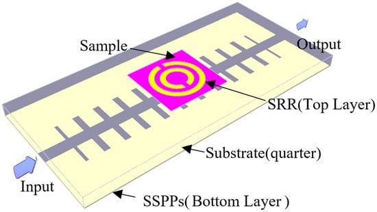
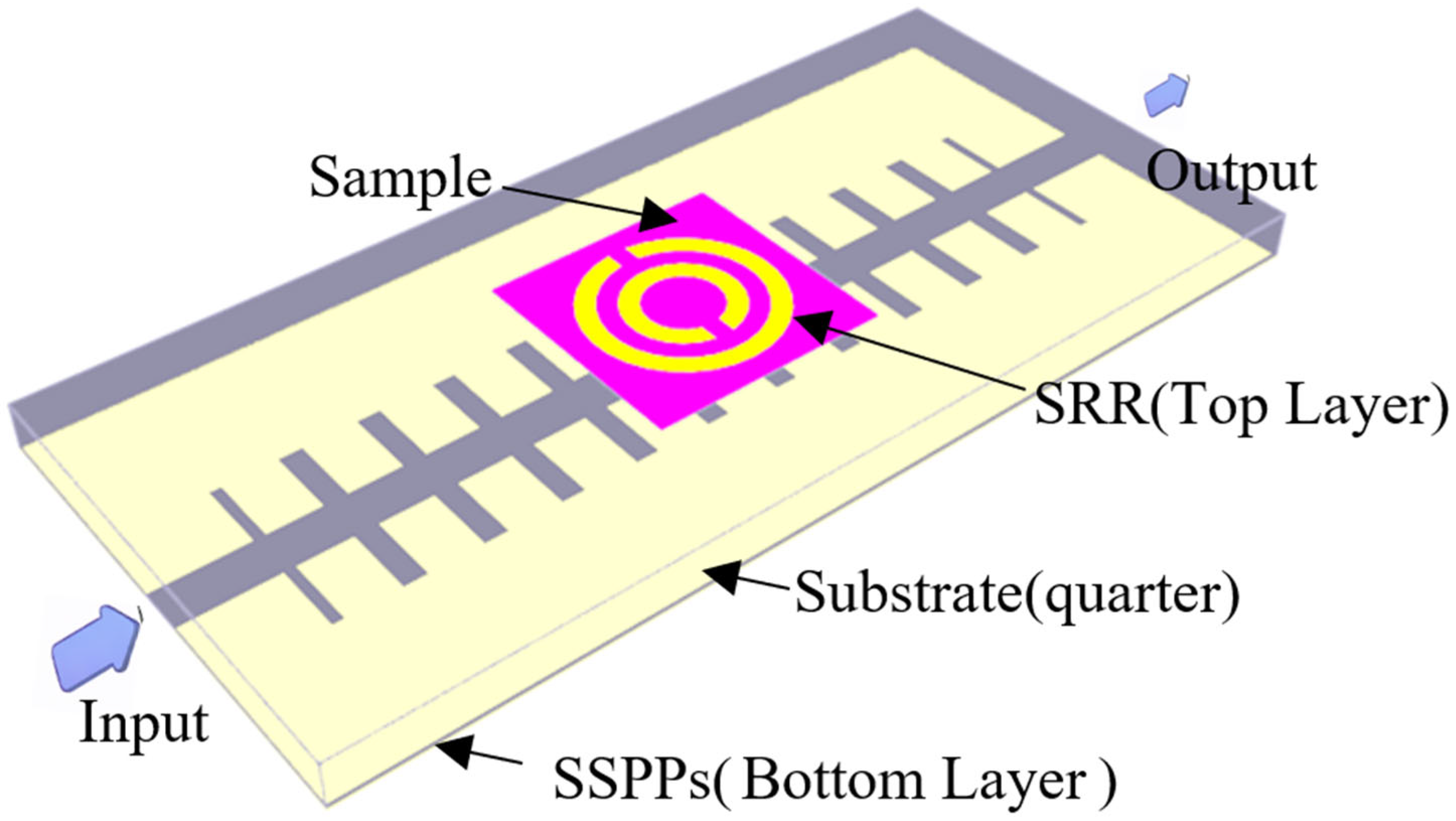
Figure 1 shows the schematic of the proposed terahertz permittivity sensor based on a coupled SSPPs–SRR structure. The sensor consists of a topside spoof surface plasmon polariton (SSPPs) transmission line and a backside split-ring resonator (SRR) implemented on a quartz substrate. The substrate has a thickness of 50 μm and a relative permittivity of 3.78. The SSPPs transmission line is formed by a periodic corrugated metallic pattern on the top side of the substrate, while the SRR is etched on the backside and positioned beneath the SSPPs coupling region. The SSPPs transmission line has a period of 80 μm and a groove depth of 75 μm. The backside resonator is a split double-ring resonator, with an outer-ring radius of 100 μm, an inner-ring radius of 50 μm, a ring width of 20 μm, and a split-gap size of 25 μm. The sample under test is loaded into the gap region of the backside SRR, where the electric field is strongly localized and the dielectric perturbation is expected to be most significant.
Figure 1.
Schematic of the proposed permittivity sensor based on an SSPPs–SRR coupled structure.
In practical operation, the topside SSPPs mode provides the guided excitation, and its evanescent field penetrates through the substrate to excite the backside SRR. Compared with directly loading the sample on the main transmission path, this configuration helps localize the perturbation to the SRR gap region and reduces undesired loading of the transition section and the SSPPs guiding channel.
Three-dimensional full-wave electromagnetic simulations were carried out in CST Studio Suite to calculate the two-port S-parameters of the proposed structure. The frequency-domain solver was used in the simulations. Waveguide ports were assigned at the two ends of the transmission line. The boundary conditions were set as open according to the simulation model. To improve numerical accuracy, local mesh refinement was applied in the SRR gap region and in the strongly coupled near-field region between the SSPPs line and the backside SRR. The simulation frequency range was set to 110–170 GHz, covering the resonance band of interest.
For dielectric sensing analysis, the relative permittivity of the sample loaded in the SRR gap region was swept from 1 to 8 while keeping the other structural parameters unchanged. From the simulated S21 responses, the notch center frequency, the 3 dB bandwidth, the notch depth, and the corresponding Q-factor were extracted for subsequent calibration and discussion.
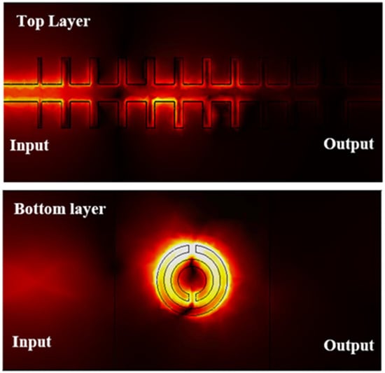
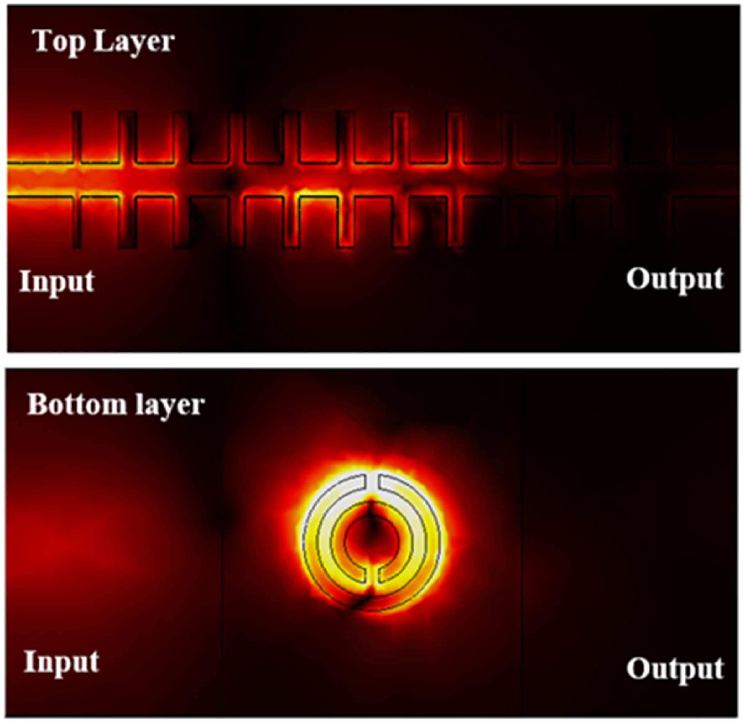
The sensing mechanism of the proposed structure is based on the evanescent-field coupling between the topside SSPPs transmission line and the backside SRR. At resonance, the electromagnetic energy is mainly concentrated in the SRR gap region, as confirmed by the simulated electric-field distribution. Therefore, when a dielectric sample is introduced into this localized high-field region, the effective capacitance associated with the SRR gap is modified, which in turn changes the resonance frequency of the coupled structure.
From an equivalent-circuit viewpoint, the resonance frequency can be approximately written as
where L denotes the effective inductance of the resonator, C0 is the intrinsic capacitance of the unloaded SRR, and Cload represents the additional effective capacitance introduced by dielectric loading in the gap region. As the relative permittivity of the loaded sample increases, the electric energy stored in the gap region increases, leading to an increase in the effective capacitance and hence a monotonic decrease in the notch center frequency. For small perturbations, the frequency shift approximately satisfies
which provides a simple physical interpretation for the observed downshift of the resonance frequency with increasing permittivity.
f0 = 1/(2 × pi × sqrt(L(C0 + Cload))
Δf0/f0 = −ΔC/2 × C
In this work, the notch center frequency is adopted as the primary sensing metric because frequency-based readout is generally less sensitive to amplitude drift and insertion-loss fluctuation than fixed-frequency amplitude interrogation. The notch depth and the Q-factor are further used as auxiliary indicators to evaluate spectral readability and coupling stability. The Q-factor is calculated as
where Δf3dB is the 3 dB bandwidth of the transmission notch.
Q = f0/Δf3dB
As shown in Figure 2, three-dimensional full-wave electromagnetic simulations were carried out in CST to analyze the S-parameter response of the proposed device. The front side of the structure consists of an SSPPs transmission line supporting guided electromagnetic-wave propagation, while the backside is a split double-ring resonator. The field distribution indicates that the resonant energy is mainly concentrated in the gap region of the split rings, demonstrating that this area is the most sensitive to dielectric loading. By filling the ring-gap region with materials of different permittivities, the equivalent inductance–capacitance (LC) parameters of the resonant structure can be modified, which in turn shifts the center resonance frequency. On this basis, the permittivity of the sample loaded in the SRR gap region was further varied to obtain the corresponding two-port S-parameter responses. The characteristic parameters, including the notch center frequency, bandwidth, and Q-factor, were then extracted from the S21 curves to establish the calibration relationship for permittivity sensing.
Figure 2.
Simulated electric-field distribution at the center resonance frequency (f0).
3. Results
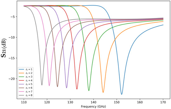
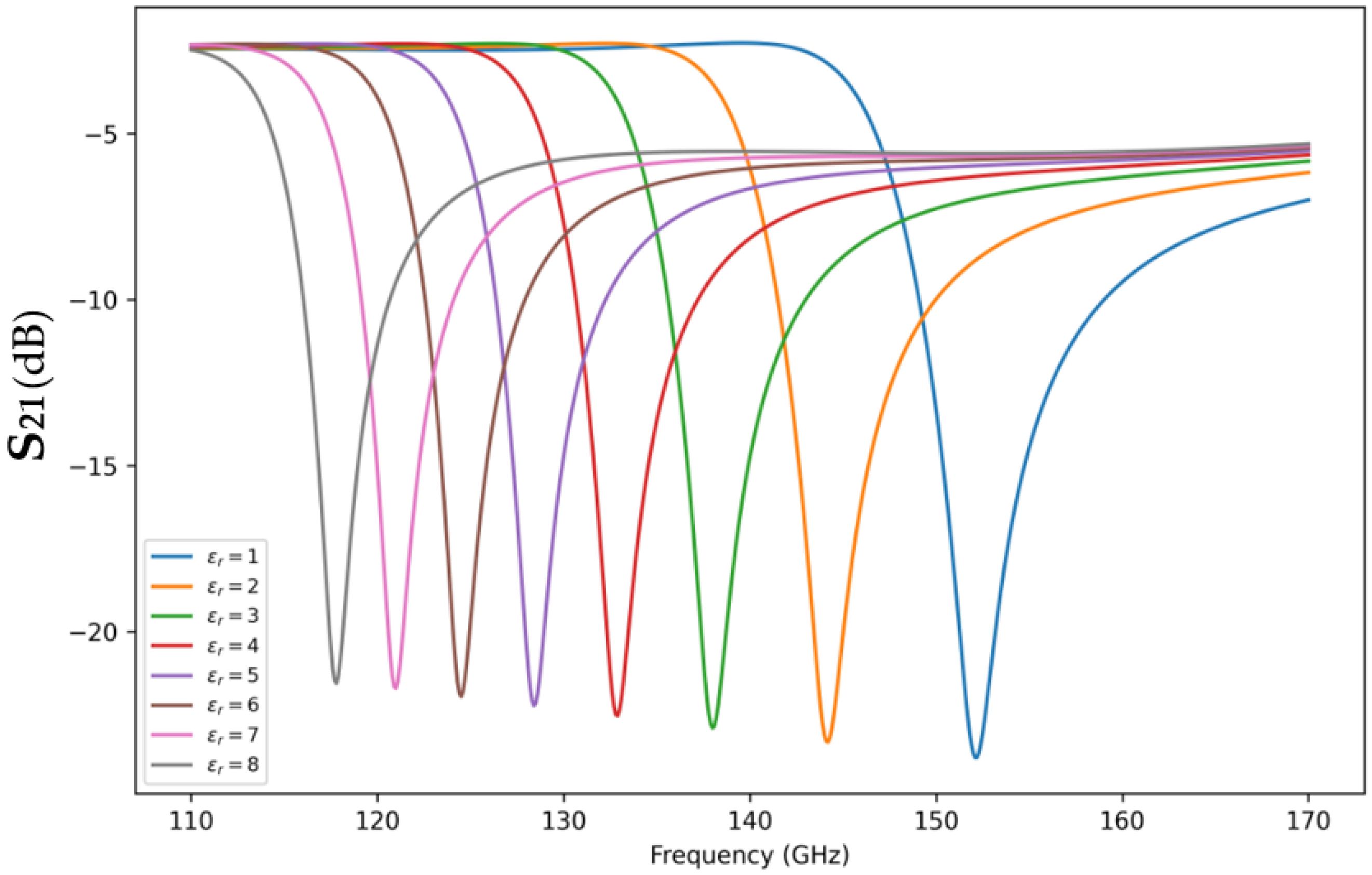
Figure 3 shows the simulated S21 responses of the proposed sensor for gap-loaded samples with relative permittivities ranging from εr = 1 to εr = 8. As the sample permittivity increases, the transmission notch shifts monotonically toward lower frequencies, while the overall spectral shape remains clearly distinguishable. The notch center frequency decreases from 152.1 GHz at εr = 1 to 117.8 GHz at εr = 8, corresponding to a total frequency shift of 34.3 GHz. Meanwhile, the minimum S21 changes from approximately −23.80 dB to −21.56 dB, indicating that the resonance notch remains sufficiently deep over the entire investigated permittivity range.
Figure 3.
Extracted ∣S21∣ responses under different relative permittivities.
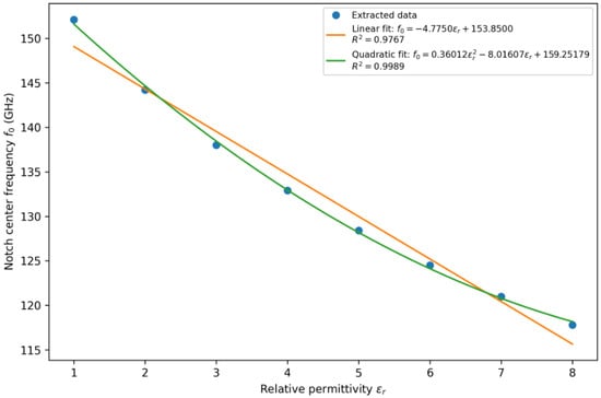
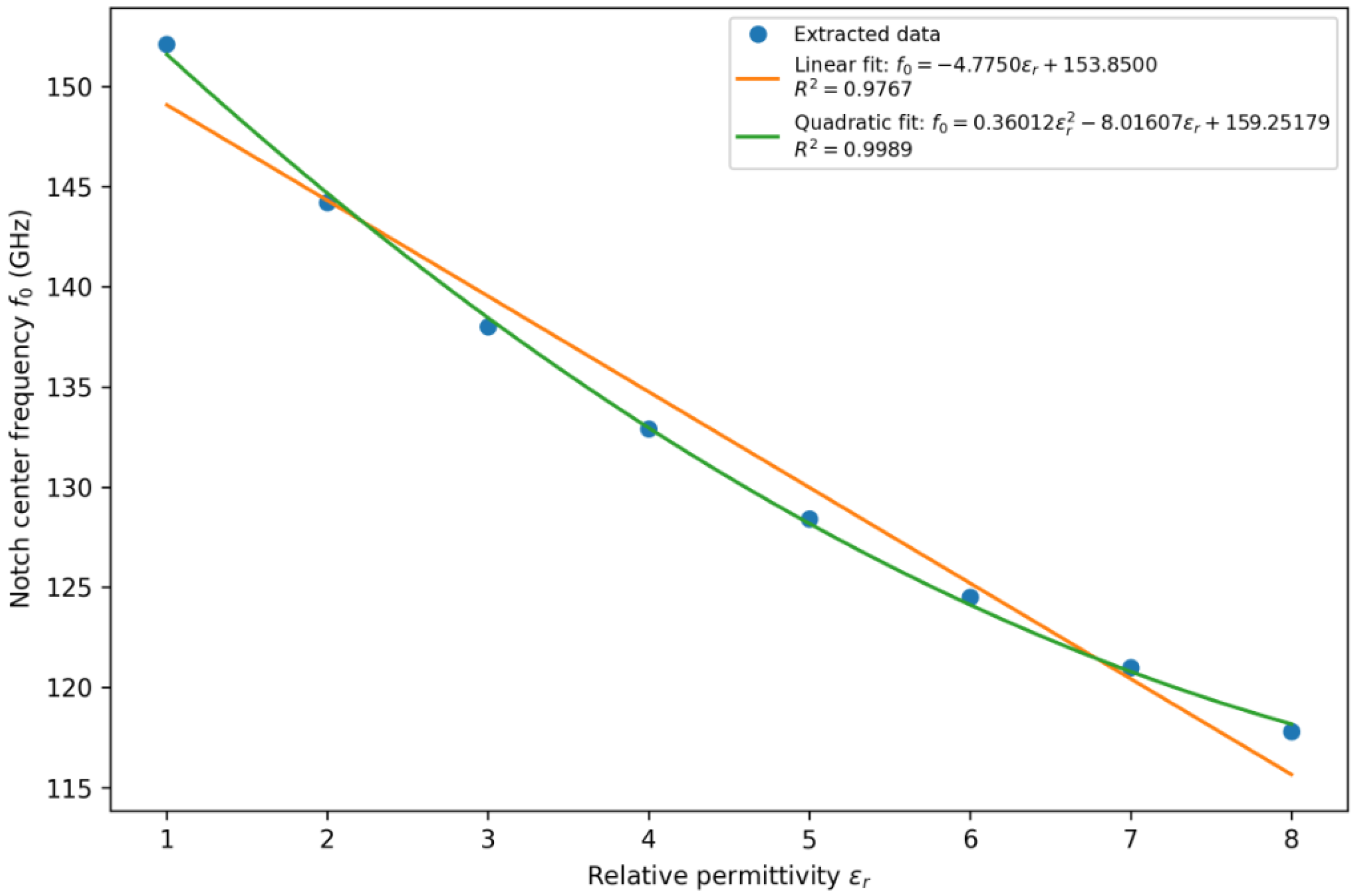
Figure 4 presents the calibration curve between the extracted notch center frequency f0 and the relative permittivity εr. The results indicate that f0 exhibits a clear monotonic negative correlation with εr, while a noticeable nonlinear trend is also observed. The linear fitting result is given by
with a goodness of fit of R2 = 0.9767. A quadratic fit further improves the fitting accuracy:
where R2 = 0.9989. Therefore, the linear model may be used as a first-order approximation for rapid estimation, whereas the quadratic model is more suitable for higher-accuracy inverse extraction.
f0(GHz) = −4.775·εr + 153.85
f0(GHz) = 0.36012·εr2 − 8.01607·εr + 159.25179
Figure 4.
Calibration curve of notch center frequency f0 versus relative permittivity εr.
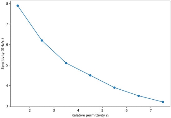
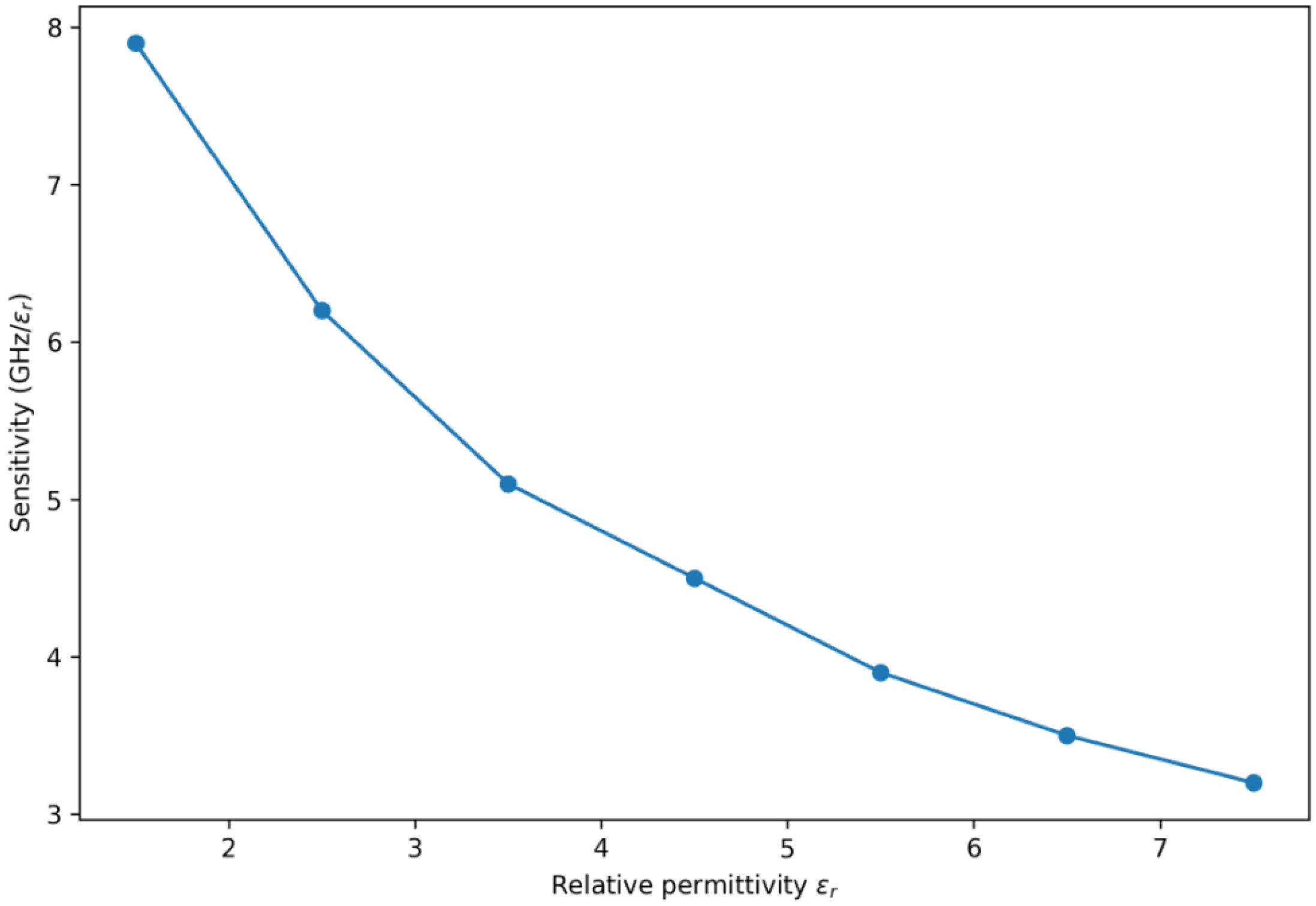
Figure 5 shows the corresponding frequency sensitivity estimated by the finite-difference method. The average sensitivity over εr = 1–8 is about 4.90 GHz/εr, although the interval sensitivity gradually decreases as the relative permittivity increases. Specifically, the sensitivity is higher in the low-permittivity region and becomes moderately smaller in the high-permittivity region, which is consistent with the observed nonlinear calibration trend.
Figure 5.
Frequency sensitivity as a function of relative permittivity.
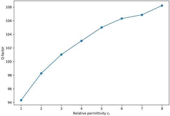
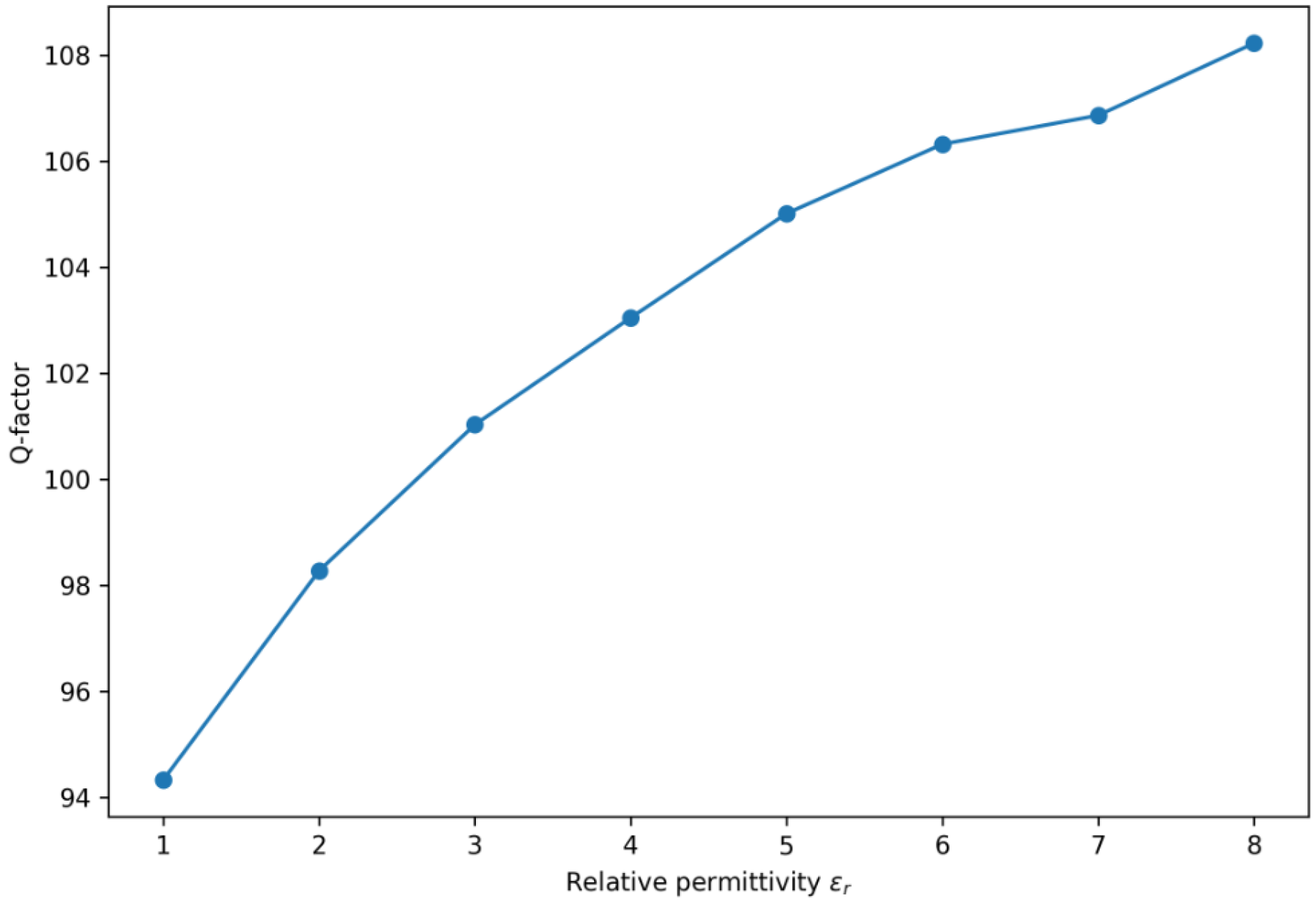
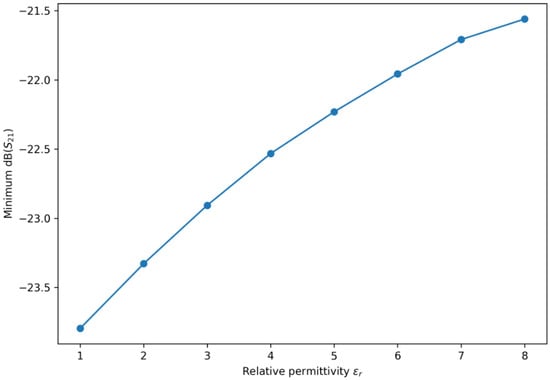
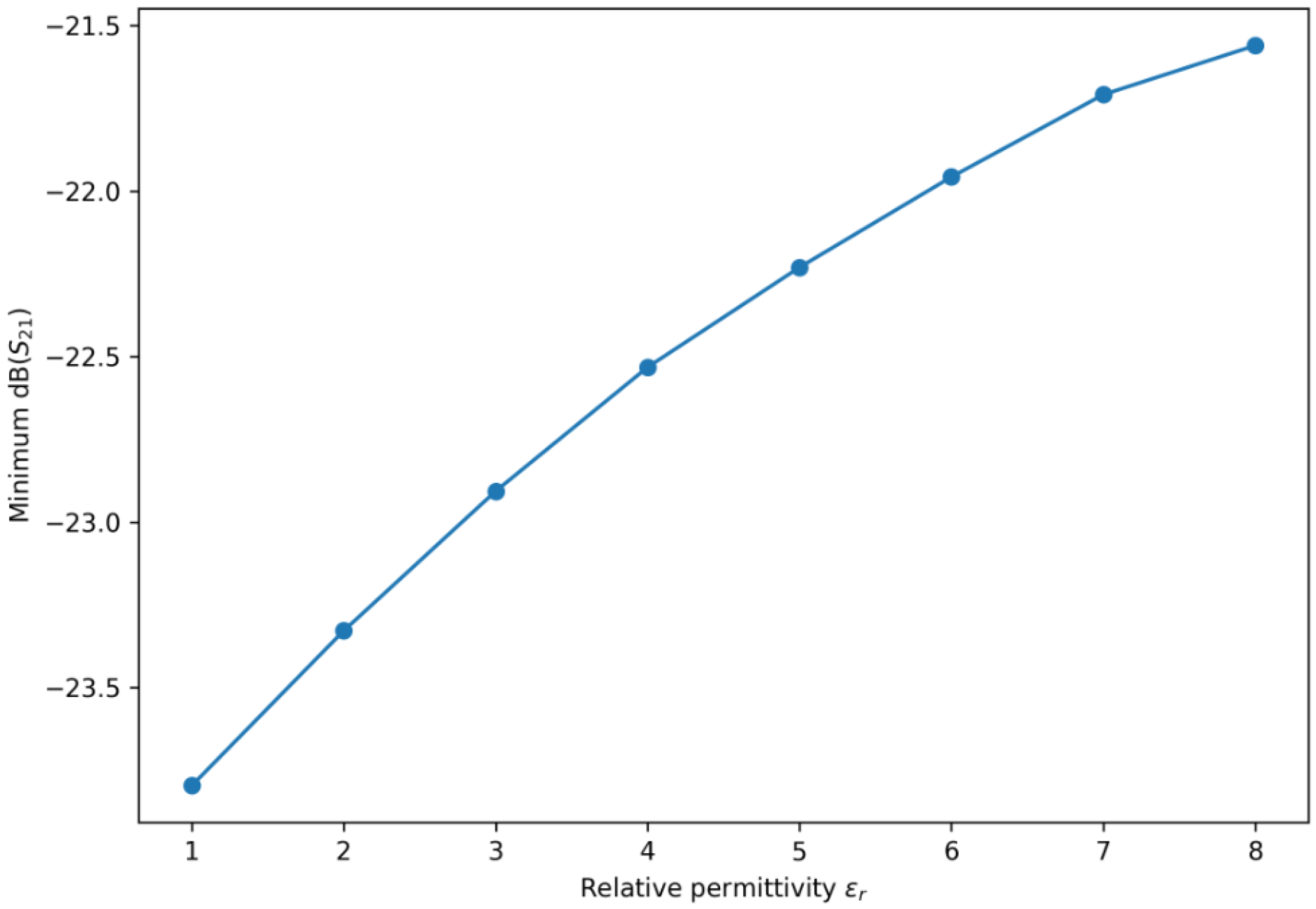
Figure 6 and Figure 7 summarize the variations in the Q-factor and notch depth with the sample permittivity. As shown in Figure 6, the Q-factor remains within 94.33–108.23, indicating that the resonance maintains a relatively narrow linewidth over the entire investigated range. The corresponding 3 dB bandwidth decreases from about 1.612 GHz to 1.088 GHz as εr increases. Figure 7 shows that the minimum S21 remains within approximately −23.80 to −21.56 dB. These results indicate that dielectric loading mainly shifts the resonance frequency, while the notch remains clearly identifiable and the spectral contrast is preserved.
Figure 6.
Q-factor as a function of relative permittivity.
Figure 7.
Notch depth as a function of relative permittivity.
From a sensing perspective, the average sensitivity of about 4.90 GHz/εr is substantially larger than the notch linewidth, indicating that a unit change in permittivity produces a clearly resolvable spectral displacement. Based on this calibration slope, a permittivity resolution of 0.1 would require a frequency resolution of about 490 MHz, while a resolution of 0.01 would require about 49 MHz. The extracted resonance parameters for all investigated loading conditions are summarized in Table 1.
Table 1.
Extracted notch parameters of the proposed sensor for εr = 1–8.
To evaluate the practical robustness of the proposed structure, additional simulations were performed for two representative perturbation cases, namely the gap-related dimensional variation and the top–bottom layer misalignment.
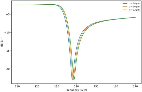
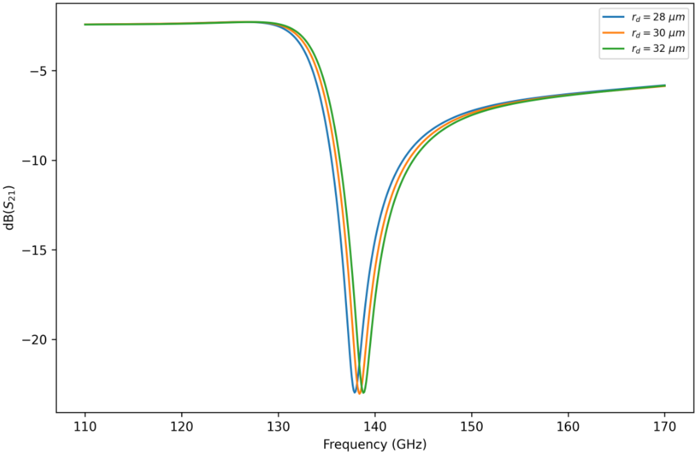
For the gap-related variation, the parameter rd was swept from 28 μm to 32 μm. The extracted resonance frequency changes from approximately 137.9 GHz to 138.8 GHz, while the minimum S21 remains close to −23 dB. This Figure 8 indicates that the gap-related dimensional perturbation mainly introduces a limited shift in the resonance baseline, whereas the notch depth changes only slightly.
Figure 8.
Simulated S21 responses for different values of the gap-related parameter rd.
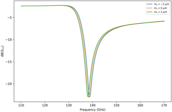
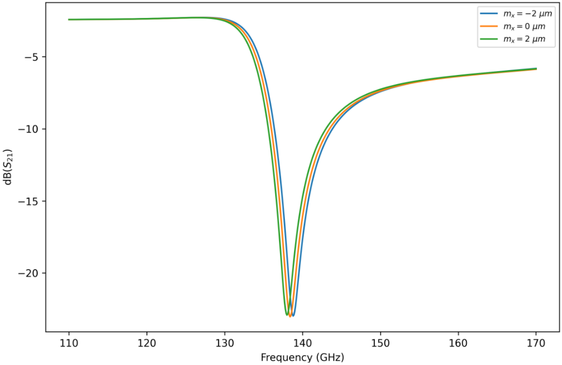
For the top–bottom misalignment case as shown in Figure 9, the lateral offset mx was swept from −2 μm to 2 μm. The corresponding resonance frequency varies from about 138.8 GHz to 138.0 GHz, again with only minor variation in the notch depth. Therefore, layer misalignment mainly affects the absolute resonance position rather than severely degrading the spectral contrast.
Figure 9.
Simulated S21 responses for different top–bottom layer misalignments mx.
These tolerance results suggest that the proposed high-Q resonant structure is sensitive to critical dimensions and alignment, which is physically consistent with the strong field localization in the SRR gap region. In practical implementation, such perturbations are more appropriately interpreted as static baseline offsets, and the proposed sensor is therefore better suited to a single-device calibrated frequency-shift sensing scheme rather than a geometry-insensitive absolute-frequency sensing scheme.
As summarized in Table 2, representative THz plasmonic/metamaterial sensors differ in operating frequency and resonance characteristics. Compared with these studies, the proposed sensor does not necessarily provide the highest performance across all THz sensing platforms, but it offers a compact dual-layer SSPPs–SRR configuration with localized backside loading and a relatively high Q-factor in the 117.8–152.1 GHz range.
Table 2.
Comparison of the proposed sensor with representative THz plasmonic/metamaterial sensors.
4. Discussion
The simulation results are consistent with the proposed sensing mechanism. As the relative permittivity of the gap-loaded sample increases from 1 to 8, the notch center frequency decreases monotonically from 152.1 GHz to 117.8 GHz, corresponding to a total frequency shift of 34.3 GHz and an average sensitivity of about 4.90 GHz per unit εr. At the same time, the minimum S21 remains within approximately −23.80 to −21.56 dB, and the Q-factor stays in the range of 94.33–108.23. These results indicate that the dominant effect of dielectric loading is the modification of the effective capacitance in the SRR gap region, which mainly shifts the resonance frequency while preserving the overall notch readability.
Compared with the original low-sensitivity calibration scenario, the updated results show that the frequency displacement caused by a unit change in permittivity is substantially larger than the notch linewidth. This means that the proposed structure provides a more clearly resolvable spectral response for permittivity sensing. In addition, the nonlinear trend in the f0-εr relation becomes more evident, so that the linear fitting may be regarded as a first-order approximation, while the quadratic fitting is more appropriate for accurate inverse extraction over the full investigated range.
The tolerance analysis further shows that both gap-related dimensional perturbation and top–bottom layer misalignment mainly manifest themselves as shifts in the absolute resonance baseline, while the notch depth remains nearly unchanged. This behavior is physically reasonable for a high-Q resonant structure with strong field localization in the SRR gap region. Therefore, the proposed sensor is more appropriately interpreted as a single-device calibrated frequency-shift sensing structure rather than a geometry-insensitive absolute-frequency sensor. In practical use, referencing the loaded-state resonance to the baseline resonance of the same device can help suppress the influence of fabrication-induced static frequency offset. For measurement resolution, the uncertainty in permittivity extraction may be estimated by Δεr ≈ Δf0/|df0/dεr|, or, under repeated loading, Δεr ≈ σf/|d f0/dεr|, where σf denotes the standard deviation of the measured resonance frequency. Based on the average sensitivity obtained in this work, a permittivity resolution of 0.1 corresponds to a frequency resolution of about 490 MHz. Future work will further address practical issues such as air gap, coverage nonuniformity, and repeated loading consistency, together with experimental validation of the proposed concept.
5. Conclusions
This work proposes a terahertz permittivity sensing structure based on an SSPPs–SRR coupled configuration. The SSPPs transmission line is patterned on the top side of the substrate, while the SRR is etched on the backside, and the sample is loaded into the highly sensitive gap region of the backside SRR. Through substrate-penetrating evanescent coupling, the SSPPs mode excites the SRR and produces a pronounced transmission notch in S21. Changes in the sample permittivity modify the effective gap capacitance and lead to a monotonic downshift of the notch center frequency.
For relative permittivities from 1 to 8, the extracted resonance frequency decreases from 152.1 GHz to 117.8 GHz, corresponding to a total shift of 34.3 GHz and an average sensitivity of about 4.90 GHz/εr. The minimum S21 remains within approximately −23.80 to −21.56 dB, while the Q-factor stays in the range of 94.33–108.23, indicating that the resonance notch remains clearly readable over the investigated range.
Tolerance analysis of the gap-related structural perturbation and top–bottom layer misalignment shows that the main effect of these perturbations is to shift the absolute resonance baseline, while the spectral notch depth is only weakly affected. Therefore, the proposed sensor is more suitable for a single-device calibrated frequency-shift sensing strategy. Overall, the proposed dual-layer SSPPs–SRR structure provides a feasible numerical route for compact terahertz permittivity sensing, and future work will focus on experimental validation and loading-consistency control.
Author Contributions
Conceptualization, S.G.; methodology, S.G. and J.Z.; simulation, C.B. and T.Z.; formal analysis, T.Z., Z.B. and C.B.; investigation, T.Z. and C.B.; data curation, C.B. and T.Z.; writing—original draft preparation, T.Z.; writing—review and editing, S.G. All authors have read and agreed to the published version of the manuscript.
Funding
This research was funded by National Natural Science Foundation of China (NO: 61901093) and Research Fund of Chengdu Medical College (NO: CYZ19-12).
Data Availability Statement
All relevant information is contained within the manuscript.
Conflicts of Interest
The authors declare no conflicts of interest.
Abbreviations
The following abbreviations are used in this manuscript:
| SSPPs | Spoof surface plasmon polaritons |
| SRR | Split-ring resonator |
| LC | Inductance–capacitance |
| FOM | Figure of merit |
References
- Liu, C.; Liao, C.; Peng, Y.; Zhang, W.; Wu, B.; Yang, P. Microwave Sensors and Their Applications in Permittivity Measurement. Sensors 2024, 24, 7696. [Google Scholar] [CrossRef] [Scilit] [PubMed]
- Alimenti, A.; Torokhtii, K.; Vidal García, P.; Pompeo, N.; Silva, E. Design and Test of a New Dielectric-Loaded Resonator for the Accurate Characterization of Conductive and Dielectric Materials. Sensors 2023, 23, 518. [Google Scholar] [CrossRef] [Scilit] [PubMed]
- Shu, M.; Shang, X.; Ridler, N.; Naftaly, M.; Guo, C.; Zhang, A. Characterisation of Dielectric Materials at G-Band (140–220 GHz) Using a Guided Free-Space Technique. In Proceedings of the 2022 52nd European Microwave Conference (EuMC), Milan, Italy, 27–29 September 2022. [Google Scholar]
- Shu, M.; Shang, X.; Ridler, N.; Calleau, A.R.; Dimitriadis, A.I.; Zhang, A. Improvements to Millimeter-Wave Dielectric Measurement Using Material Characterization Kit (MCK). IEEE Trans. Instrum. Meas. 2023, 73, 6001108. [Google Scholar] [CrossRef] [Scilit]
- Baena, J.; Bonache, J.; Martin, F.; Sillero, R.; Falcone, F.; Lopetegi, T.; Laso, M.; Garcia-Garcia, J.; Gil, I.; Portillo, M.; et al. Equivalent-Circuit Models for Split-Ring Resonators and Complementary Split-Ring Resonators Coupled to Planar Transmission Lines. IEEE Trans. Microw. Theory Tech. 2005, 53, 1451–1461. [Google Scholar] [CrossRef] [Scilit]
- Isakov, D.; Stevens, C.J.; Castles, F.; Grant, P.S. A Split Ring Resonator Dielectric Probe for Near-Field Dielectric Imaging. Sci. Rep. 2017, 7, 2038. [Google Scholar] [CrossRef] [Scilit] [PubMed]
- Ma, J.; Tang, J.; Wang, K.; Guo, L.; Gong, Y.; Wang, S. Complex permittivity characterization of liquid samples based on a split ring resonator (SRR). Sensors 2021, 21, 3385. [Google Scholar] [CrossRef] [Scilit] [PubMed]
- Navaei, M.; Rezaei, P.; Kiani, S. Microwave Split Ring Resonator Sensor for Determination of the Fluids Permittivity with Measurement of Human Milk Samples. Radio Sci. 2022, 57, e2022RS007435. [Google Scholar] [CrossRef] [Scilit]
- Pittella, E.; Piuzzi, E. Split Ring Resonator for Complex Permittivity Measurement. In Proceedings of the 24th IMEKO TC4 International Symposium and 22nd International Workshop on ADC and DAC Modelling and Testing, Palermo, Italy, 14–16 September 2020. [Google Scholar]
- Masrakin, K.; Ibrahim, S.Z.; Rahim, H.A.; Azemi, S.N.; Soh, P.J.; Tantiviwat, S. Microstrip Sensor Based on Ring Resonator Coupled with Double Square Split Ring Resonator for Solid Material Permittivity Characterization. Micromachines 2023, 14, 790. [Google Scholar] [CrossRef] [Scilit] [PubMed]
- Ds, C.; Nagini, K.B.S.S.; Barik, R.K.; Koziel, S. Highly Sensitive Microwave Sensors Based on Open Complementary Square Split-Ring Resonator for Sensing Liquid Materials. Sensors 2024, 24, 1840. [Google Scholar] [CrossRef] [Scilit] [PubMed]
- Pendry, J.B.; Martín-Moreno, L.; García-Vidal, F.J. Mimicking Surface Plasmons with Structured Surfaces. Science 2004, 305, 847–848. [Google Scholar] [CrossRef] [Scilit] [PubMed]
- García-Vidal, F.J.; Martín-Moreno, L.; Pendry, J.B. Surfaces with Holes in Them: New Plasmonic Metamaterials. J. Opt. A 2005, 7, S97–S101. [Google Scholar] [CrossRef] [Scilit]
- Podunavac, I.; Radonic, V.; Bengin, V.; Jankovic, N. Microwave Spoof Surface Plasmon Polariton-Based Sensor for Ultrasensitive Detection of Liquid Analyte Dielectric Constant. Sensors 2021, 21, 5477. [Google Scholar] [CrossRef] [Scilit] [PubMed]
- Tan, L.; Guo, Y.; Shu, Z.; Xu, K.-D. Spoof Surface Plasmon Polaritons Based On-Chip Sensor for Dielectric Detection. Opt. Express 2023, 31, 2039–2048. [Google Scholar] [CrossRef] [Scilit] [PubMed]
- Kim, Y.; Salim, A.; Lim, S. Millimeter-Wave-Based Spoof Localized Surface Plasmonic Resonator Sensor (for glucose measurement). Biosensors 2021, 11, 358. [Google Scholar] [CrossRef] [Scilit] [PubMed]
- Chen, X.; Fan, W. Ultrasensitive Terahertz Metamaterial Sensor Based on Spoof Surface Plasmon. Sci. Rep. 2017, 7, 2092. [Google Scholar] [CrossRef] [Scilit] [PubMed]
- Unutmaz, M.A.; Unlu, M. Terahertz spoof surface plasmon polariton waveguides: A comprehensive model with experimental verification. Sci. Rep. 2019, 9, 7616. [Google Scholar] [CrossRef] [Scilit] [PubMed]
- Liu, G.; Cheng, D.; Zhang, B.; Shu, G.; Wang, J. A Microwave Biosensor Based on Spoof Surface Plasmon Polaritons for In Vivo Measurement of the Water Content of Human Skin Tissues. J. Phys. D Appl. Phys. 2019, 52, 205401. [Google Scholar] [CrossRef] [Scilit]
- Ma, A.; Zhong, R.; Wu, Z.; Wang, Y.; Yang, L.; Liang, Z.; Fang, Z.; Liu, S. Ultrasensitive THz Sensor Based on Centrosymmetric F-Shaped Metamaterial Resonators. Front. Phys. 2020, 8, 584639. [Google Scholar] [CrossRef] [Scilit]
- Li, X.; Zheng, G.; Zhang, G.; Yang, J.; Hu, M.; Li, J.; Li, Y.; Lu, H.; Yin, Z. Highly Sensitive Terahertz Dielectric Sensor for Liquid Crystal. Symmetry 2022, 14, 1820. [Google Scholar] [CrossRef] [Scilit]

Disclaimer/Publisher’s Note: The statements, opinions and data contained in all publications are solely those of the individual author(s) and contributor(s) and not of MDPI and/or the editor(s). MDPI and/or the editor(s) disclaim responsibility for any injury to people or property resulting from any ideas, methods, instructions or products referred to in the content. |
© 2026 by the authors. Licensee MDPI, Basel, Switzerland. This article is an open access article distributed under the terms and conditions of the Creative Commons Attribution (CC BY) license.