


Abstract
To tackle the drawbacks of small effective area and limited incident angle in conventional Fabry–Pérot (F-P) etalons, this paper presents a high-utilization laser frequency-selective ultra-narrow band F-P filter module, along with systematic investigations into its operating principle, simulation, design, and verification. A simulation model with a central wavelength of 532.20 nm (±0.1 nm) and a free spectral range of 300 pm is developed, and a prototype filter is fabricated accordingly. The prototype exhibits a transmission peak linewidth better than 0.037 nm and a peak transmittance over 68%, matching well with the simulation. Simulations also reveal symmetric high-transmittance peaks at ±2.9° with stable frequency selection performance. On this basis, an integrated module is proposed using field-of-view angle conversion and optical path multiplexing. Under combined incidence at 0° and ±2.9°, the module achieves 1.67 times the energy of single-angle incidence while satisfying wavelength and bandwidth requirements. The proposed structure breaks through the conventional normal-incidence restriction and offers a novel approach for high-efficiency, multi-angle multiplexing applications of F-P etalons in precision optical systems.
1. Introduction
As a high-resolution interference optical device based on the principle of multi-beam interference, the Fabry–Pérot (F-P) etalon is one of the preferred devices for aerospace laser filtering systems due to its core advantages such as narrow bandwidth and strong anti-interference ability, and it has extensive application value in many fields. In the aerospace engineering field, narrow band laser systems are the core components of key missions such as precision measurement, remote sensing detection [1,2,3], satellite navigation, and atmospheric and oceanic detection [4,5,6,7,8]. Beyond the aerospace field, high-precision F-P etalons are also widely used in spectral research, length metrology, laser technology, and precision optical testing [6,7]: as filters, they can be used to fabricate narrow band interference filters and tunable filters [9] for laser resonant cavities and laser frequency stabilization systems; as optical frequency discriminators, they can perform spectral measurements of different frequencies [10] for constructing ultra-fine spectral detection systems and optical wavemeters, and they can also be used to measure physical parameters such as the refractive index of optical crystal materials [11]. In spaceborne hyperspectral imaging, atmospheric detection differential absorption lidar, astronomical high-resolution spectral observation, as well as precision laser frequency stabilization and narrow-linewidth laser systems, Fabry–Perot etalon-based filter modules are widely used to achieve high-precision selection of target spectra, stray light suppression, background signal rejection, and effective signal enhancement, owing to their advantages of narrow transmission lines, accurate wavelength positioning, and compact and stable structure. For environmental monitoring, resource exploration, and disaster early warning, the filtering requirements are generally a central wavelength shift of no more than 0.02 nm and a transmission spectral width within 0.1 nm. For the quantitative inversion of greenhouse gases, aerosols, and pollutant concentrations, filter modules are required to have a peak wavelength accuracy better than ±0.02 nm, with a transmission linewidth of 0.05–0.1 nm, so as to ensure the accuracy and stability of concentration inversion and improve the suppression ratio. However, the demand for high light energy utilization efficiency in filter systems is increasingly urgent and continuously expanding in the optical field [12].
Traditional F-P filters only use normal or near-normal incident light, resulting in limited signal collection under a fixed clear aperture and low utilization efficiency. Cascaded FP etalons still operate under normal incidence; although they can achieve narrower linewidth and higher sidelobe suppression ratio, they provide no significant improvement in energy harvesting and have low angular tolerance. The multi-angle multiplexed FP module in this paper achieves higher peak energy than the traditional single FP etalon. In contrast, the energy throughput of cascaded FP etalons is generally lower than that of conventional FP devices due to machining accuracy and other issues, with transmittance typically ranging from 30% to 60%. The single multiplexed FP module features lower cost, wider angular acceptance range, and lower system complexity. Volume Bragg gratings (VBG) are commonly used optical filtering devices with a typical linewidth of 0.1–0.5 nm. Their diffraction efficiency is highly sensitive to the incident angle: a small deviation from the Bragg angle leads to a sharp drop in diffraction efficiency, so they are often used in laser beam combining and spectral shaping applications. MEMS-based tunable FP filters allow adjustable transmission wavelengths, mainly tuned via electromagnetic or pressure actuation. Limited by control system precision, the cavity length is prone to deformation under external forces, resulting in weak vibration and shock resistance. Their accuracy and linewidth performance are inferior to those of narrow band solid-state FP etalons, with a typical linewidth range of 5–20 nm. Although it achieves satisfactory peak selection performance, it is still insufficient for high-precision detection applications. High-efficiency F-P modules are crucial for improving the signal-to-noise ratio, detection accuracy, and environmental adaptability of various precision optical systems. In multi-point detection, multi-field-of-view reception, and large-angle incident optical systems, it is necessary to realize simultaneous reception, filtering, and detection of multi-channel signals. Through a multi-angle incidence structure, simultaneous processing of multi-field-of-view and multi-directional optical signals can be accomplished in a single filter device, meeting the requirements of system integration, miniaturization, and high detection efficiency for multi-point detection. This is especially suitable for scenarios requiring multi-channel parallel detection, such as laser radar, space remote sensing, and hyperspectral imaging. Based on the principle of F-P filtering, this paper analyzes its frequency-selective characteristics using optical simulation software [13,14] and simulates the filtering characteristic law under multi-angle incidence. Meanwhile, a high-utilization laser frequency-selective ultra-narrow F-P filter module is designed to realize multi-angle multiplexing of optical signals with different fields of view based on the optical path, and the overall system design and simulation of the high-utilization module are completed. This research provides technical support and engineering reference for the research and development of aerospace laser optical systems, and also offers a new idea for the high-utilization application of F-P etalons in other precision optical systems [15,16].
2. Working Principle of the F-P Filter Module
The working basis of the F-P filter module is the multi-beam interference effect between parallel plane reflectors, which realizes high-precision frequency/wavelength selection and measurement of optical signals. Its working principle determines the narrow band filtering characteristic and high spectral resolution of the device and also provides a theoretical basis for the utilization of multi-angle incident light. The core structure of the F-P etalon consists of two parallel high-reflectivity plane reflectors, with a resonant cavity of fixed thickness formed between them. The medium of the resonant cavity can be air, vacuum or other optical media [17].
2.1. Basic Theory of Multi-Beam Interference
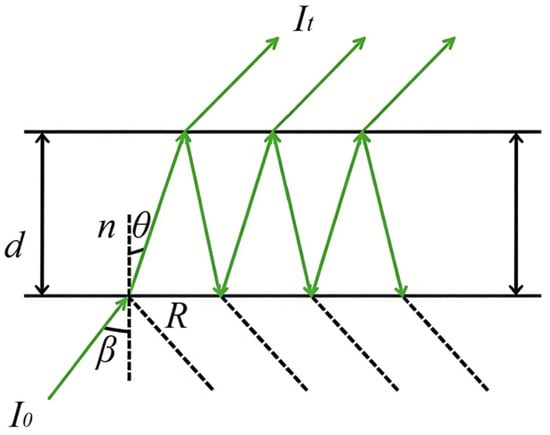
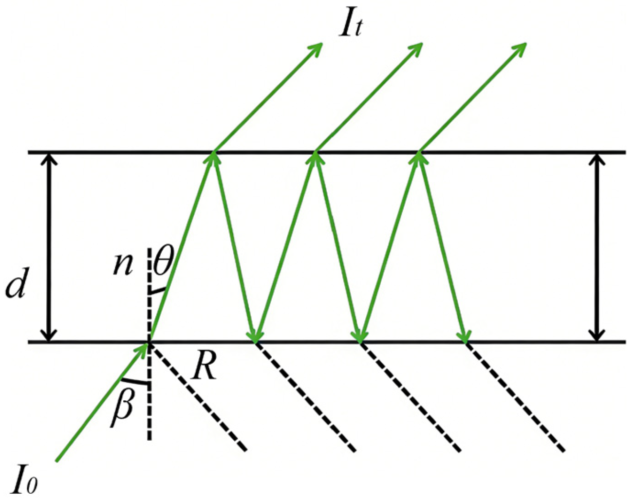
When a monochromatic light is incident on the incident-end reflector of the F-P etalon at an incident angle θ, the optical signal undergoes multiple reflections and transmissions between the two parallel reflectors, forming multiple coherent transmitted and reflected light beams [17,18]. Since the multiple transmitted light beams originate from the same incident light and satisfy the coherence conditions of light, they superpose and interfere in space, and the interference result is determined by the phase difference of each transmitted light beam, as shown in Figure 1.
Figure 1.
Fabry–Pérot etalon.
Let the wavelength of the incident light be λ, and the optical thickness of the resonant cavity of the F-P etalon be nd (where n is the refractive index of the resonant cavity medium, and d is the physical thickness of the resonant cavity). According to the geometric propagation relationship and phase-change law of light, the phase difference δ between two adjacent transmitted light beams can be expressed as:
- where θ is the propagation angle of light in the resonant cavity;
- n is the refractive index of the resonant cavity medium;
- d is the physical thickness of the resonant cavity.
The resultant amplitude of the superposed multiple coherent transmitted light beams is determined by the amplitude of each transmitted light beam and the phase difference between adjacent beams. Assuming the reflectivity and transmittance of the F-P etalon reflector are R and T, respectively, and neglecting the absorption loss of the optical signal during propagation and reflection, the resultant amplitude transmittance T of the multiple transmitted light beams can be derived according to the principle of coherent superposition of light, with its expression given as follows:
where It is the transmitted light intensity, I0 is the incident light intensity, and T0 is the initial transmittance of the reflector, which serves as the core theoretical basis for the parameter design of the F-P filter module [18].
2.2. Realization Conditions of Ultra-Narrow Band Filtering
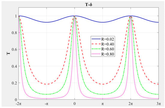
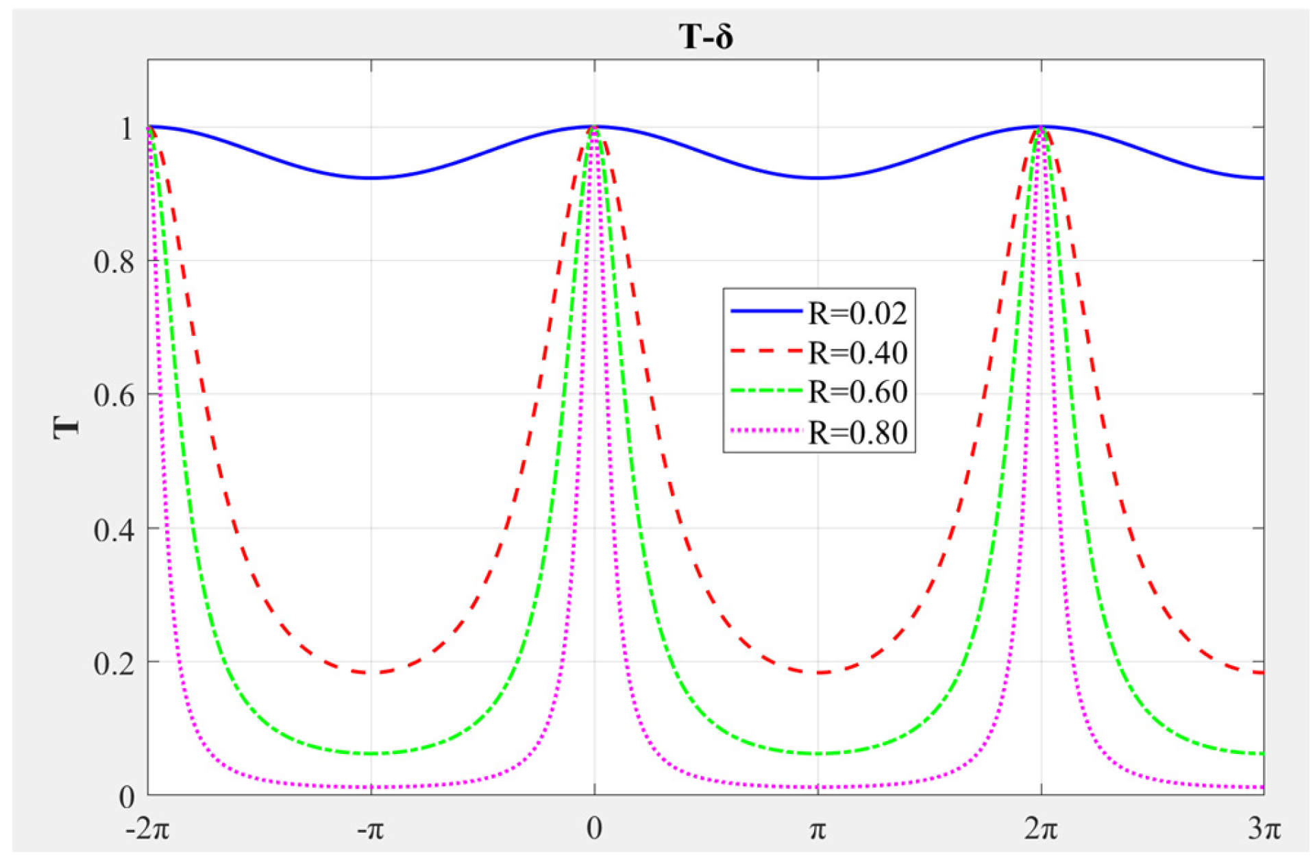
It can be seen from the transmittance formula that the transmittance of the F-P etalon changes periodically with the phase difference δ. When the phase difference satisfies the constructive interference condition, the transmittance reaches the maximum value, forming a transmission peak; when the phase difference satisfies the destructive interference condition, the transmittance approaches 0, and the optical signal is greatly attenuated. The condition for constructive interference is that the phase difference between two adjacent transmitted light beams is an integer multiple of 2π, as shown in Figure 2.
Figure 2.
Characteristic curve of a FP etalon.
k is the interference order and a positive integer. Substituting the phase difference formula into the constructive interference condition, the matching condition of the incident light wavelength can be obtained by the following equation:
When the wavelength of the incident light satisfies the above formula, the optical signal of this wavelength will produce constructive interference in the F-P etalon, forming a maximum transmission peak. Other wavelengths will experience transmittance attenuation due to destructive interference, thus realizing the selection of optical signals with specific wavelengths to achieve the filtering purpose. The wavelength difference between two adjacent transmission peaks is the free spectral range FSR = λ^2/(2ndcosθ), which is an important performance index of the F-P filter module and determines the effective filtering band range of the device. The reflectivity R affects the filtering bandwidth but has no influence on the central wavelength of frequency selection. The ultra-narrow band filtering characteristic of the F-P etalon is closely related to R: the higher the reflectivity, the narrower the linewidth of the transmission peak.
The spacing between two adjacent maxima of this function is defined as the free spectral range (FSR) of the etalon, and the spectral width of the transmission peak is referred to as the full width at half maximum (FWHM) of the etalon. The ratio of these two quantities, denoted as F, is called the finesse of the etalon. The finesse (F) of a Fabry–Pérot etalon characterizes the steepness of its transmission peaks, which in turn determines its spectral resolution. In the ideal case, F is determined by the reflectivity of the coated films and can be expressed by the following formula:
The higher the reflectance R, the larger the finesse F. From the relation Δλ = FSR/F, it can be seen that a larger F results in a smaller linewidth Δλ, which means that a higher reflectance leads to narrower transmission peaks and a stronger ultra-narrow band filtering capability. Under practical conditions, both the finesse, which characterizes the spectral linewidth of the etalon, and the peak transmittance, which characterizes the transmitted energy of the etalon, are affected by multiple factors. While the finesse of an ideal etalon is determined solely by the mirror reflectance, phase errors in the interfering beams caused by flatness and parallelism errors, as well as diffraction losses due to the finite clear aperture, result in a significant reduction in the overall finesse compared to the ideal mirror condition.
3. Simulation of Laser Frequency-Selective Performance of the F-P Filter Module
3.1. Construction of the Simulation Model
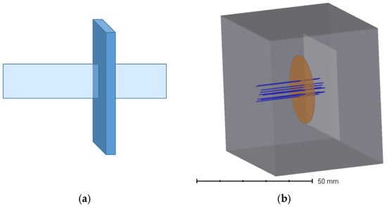
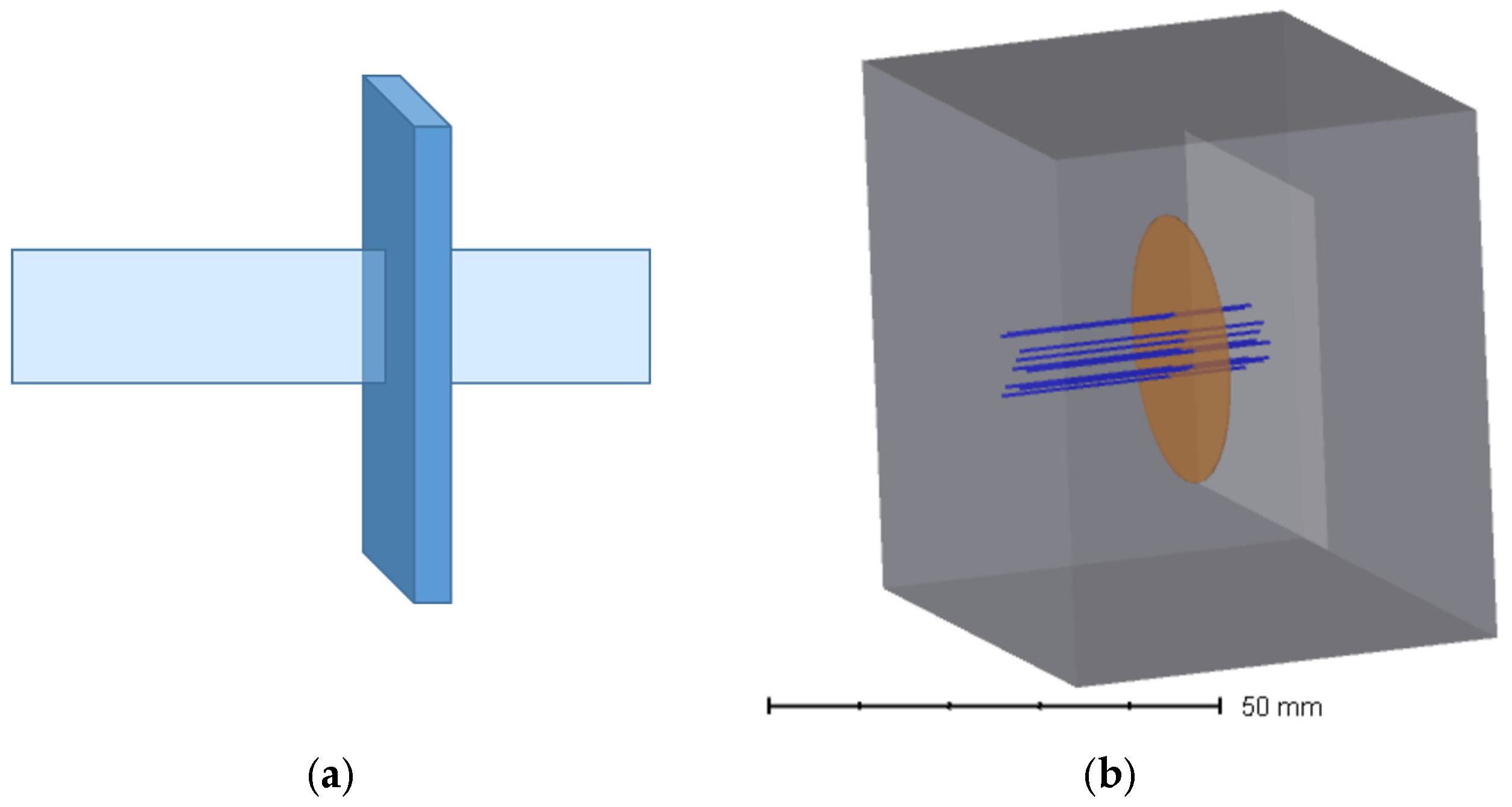
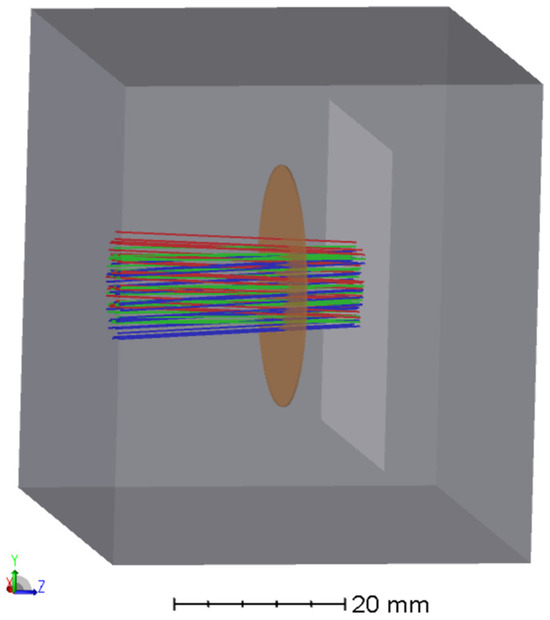
The requirements for F-P filtering are as follows: a central wavelength of 532.20 nm (±0.01 nm), a FSR of 300 pm, and a bandwidth less than 0.06 nm. The system simulation is carried out using ZEMAX optical software, and a simulation model of the ultra-narrow band filtering for the laser frequency-selective F-P filter module is established, as shown in Figure 3. In the non-sequential mode, according to the core structure of the F-P etalon, the laser optical axis was set to coincide with the central axis of the F-P etalon with an incident angle of 0°. The simulation module mainly consists of four parts: a laser light source, an environment module, a F-P filter, and a light intensity detection system. Through optimal design, the solid F-P etalon adopts glass material with a refractive index of 1.495 and a thickness d of 0.3157965 mm, with the air refractive index n0 = 1.029. In the simulation system, the coating parameter in the coating setup was set to an average reflectivity of 0.69 to correspond to the actual processing thickness for simulation. The power is set to unity (for the convenience of theoretical normalized calculation; in practical laser detection applications, the far-field echo received signal is much less than 1 W, on the order of milliwatts or below, and the actual incident power can be used as the input accordingly). The simulation is started after setting the number of rays to more than 4000. The light intensity detection system receives the optical signal energy transmitted through the F-P filter module and records key performance indicators such as optical field intensity and peak position. The simulation is repeated with varying wavelengths for data processing.
Figure 3.
Schematic Diagrams: (a) Schematic diagram of F-P etalon under normal incidence and (b) schematic diagram of F-P etalon under normal incidence in optical simulation software.
3.2. Simulation of Filtering Characteristics
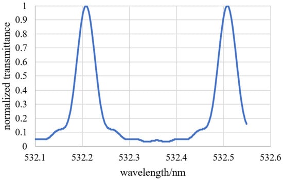
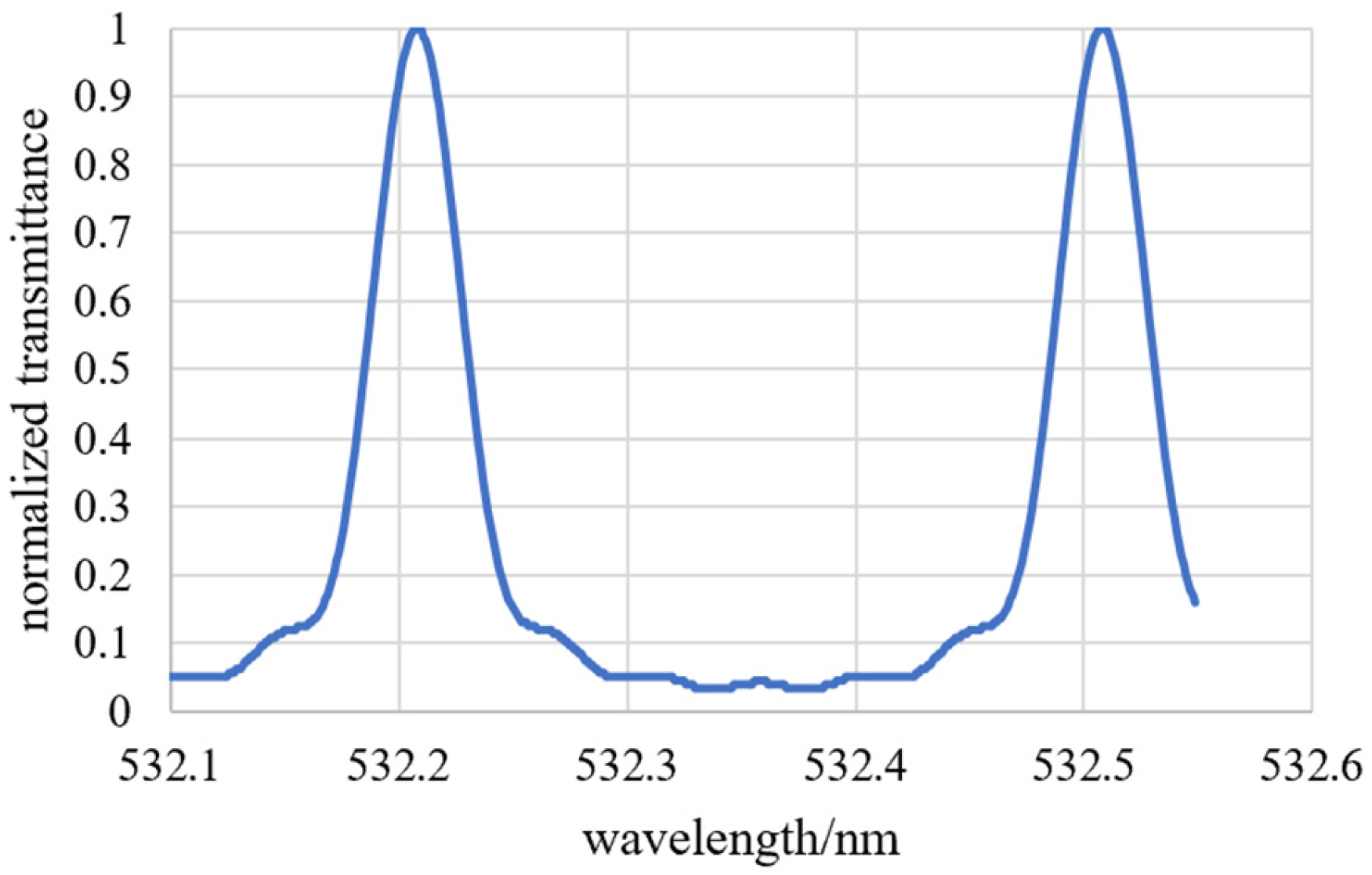
Normal incidence is the traditional operating mode of the F-P etalon and also the foundation for verifying the narrow band filtering performance of the module. This design is oriented to underwater laser detection, where a filter with a peak wavelength of 532.2 nm and a linewidth less than 0.06 nm is required to meet the detection specifications. Therefore, a theoretical reflectivity of R = 0.69 and a finesse of F = πR1/2/(1 − R) = 8.43 are adopted in the simulation. In this simulation, the transmittance is obtained by varying the wavelength and calculating the optical power received by the detector [14], so as to realize ultra-narrow band filtering at the designated wavelength near the 532 nm band. The results are normalized as shown in Figure 4.
Figure 4.
Schematic diagram of normalized transmittance under normal incidence.
It can be seen from the simulation results that the designed F-P filter module presents peak transmittance at 532.208 nm and 532.508 nm. The interval between the two maxima, defined as the free spectral range (FSR) of the etalon, is 0.3 nm. According to both theoretical calculation and simulation results, Δλ = FSR/F = 0.037 nm, which is smaller than the 0.06 nm required for engineering applications of laser frequency-selective ultra-narrow band filtering.
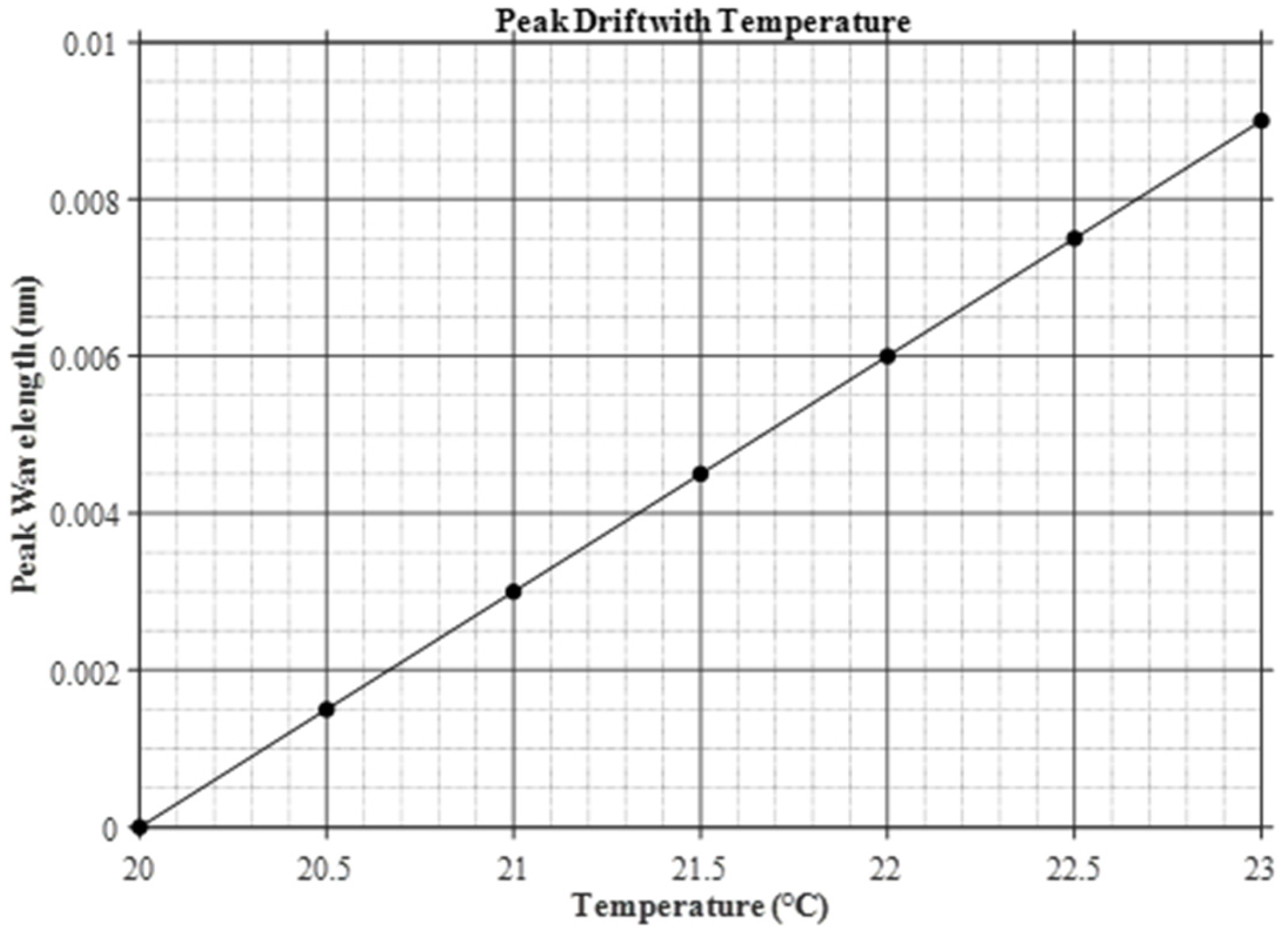
We performed an environmental analysis on the FP multiplexing module. The solid FP etalon uses self-developed J4 glass with a thermal expansion coefficient of α = 5.6369 × 10⁻⁶. Since the thickness of the FP material varies with temperature increase or decrease, the peak wavelength shift trend can be expressed by the following formula.
where T is temperature, n is the refractive index, and λ0 is the central wavelength. Since the refractive index of this material is insensitive to temperature variations, we set dn/dT = 0, and the formula is thus simplified as:
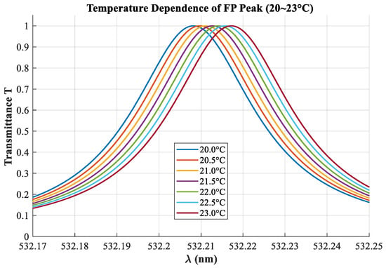
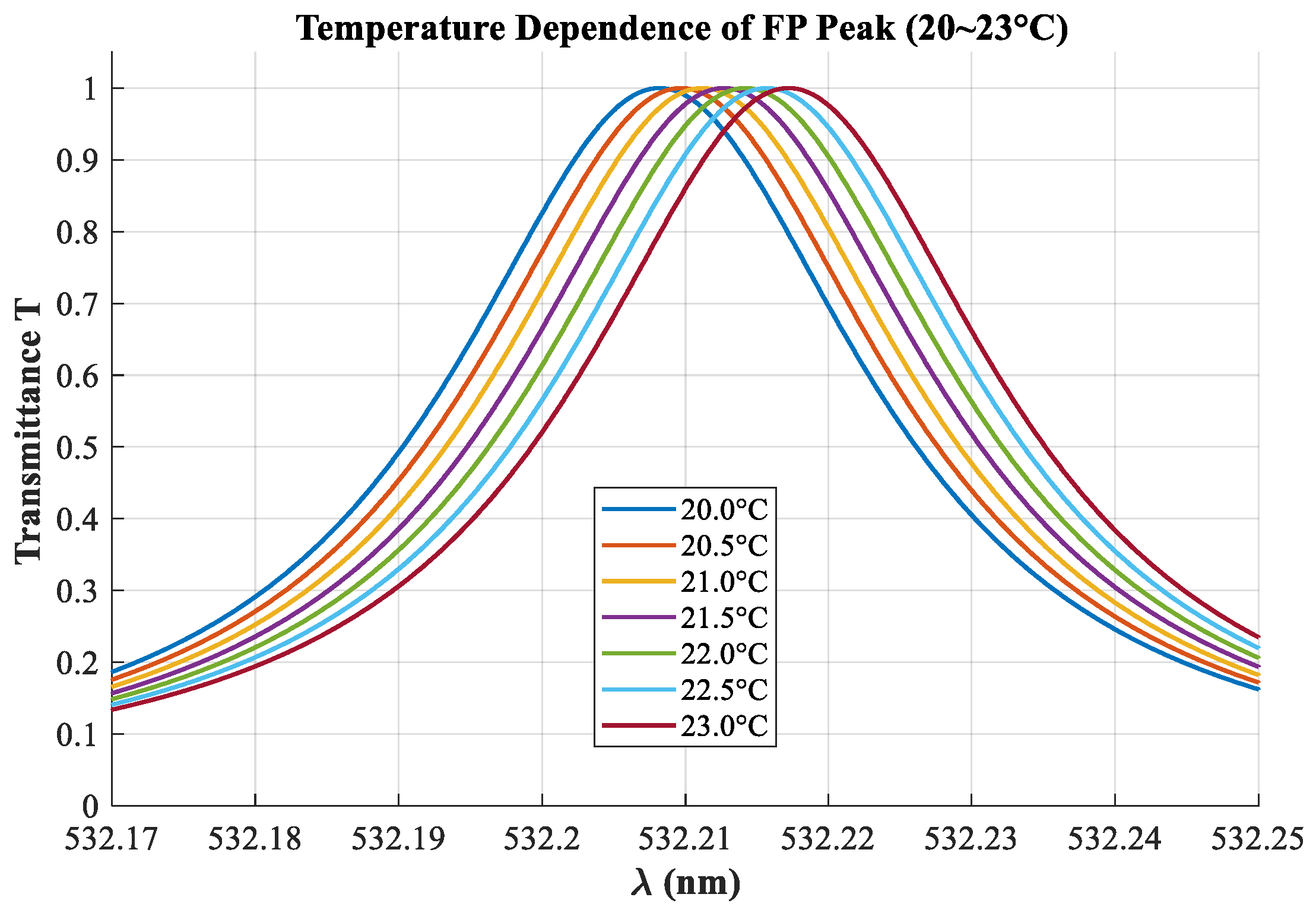
Simulations were performed on the peak position variation in the FP module with temperature. Since the peak positions for normal incidence and oblique incidence (±2.9°) are identical at λ0, the peak position shift of the FP multiplexing module versus temperature at different incident angles is shown in Figure 5, and the wavelength–transmittance curves of the FP multiplexing module versus temperature are shown in Figure 6.
Figure 5.
Peak drift with temperature.
Figure 6.
Temperature dependence of FP peak (20~23 °C).
Considering that temperature affects the transmittance peak of the FP etalon, the commonly used temperature control method at present is to adopt a customized sealed water-circulation temperature control system, equipped with a circulation monitoring device for real-time monitoring of the ambient temperature of the FP module. The water-circulation temperature control ensures stable wavelength matching of the system by absorbing or releasing heat, thus meeting the offset accuracy requirements of the detection wavelength.
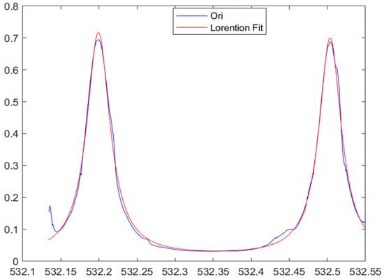
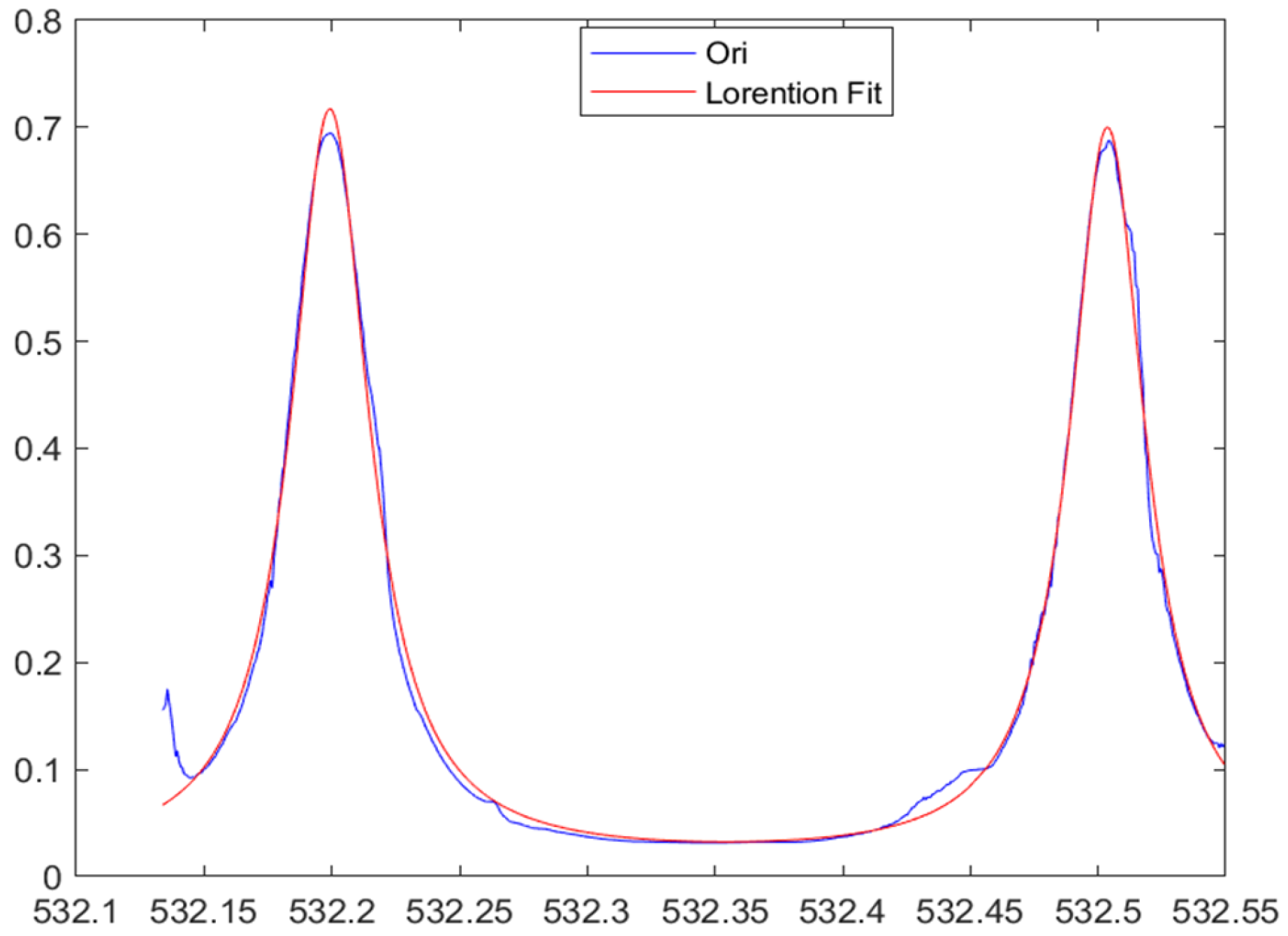
A solid ultra-narrow F-P filter was fabricated based on the simulation parameters, as shown in Figure 7. The solid-state F-P etalon adopts glass material with a refractive index of 1.495. The theoretical thickness of the F-P etalon is d = 0.3159 mm, and the initial processing thickness is d = 0.316 mm, with an air refractive index n0 = 1.029. The coating is fabricated by stacking TiO2 with a refractive index of 2.4 and SiO2 with a refractive index of 1.5 at thicknesses of 50 nm and 80 nm respectively, and the total thickness is controlled between 800 nm and 900 nm. A parallel optical path is built at the processing site, and follow-up production tests are carried out using a spectrometer. The finishing direction of the substrate and coating thickness is guided by measured parameters such as the transmittance half-width and peak position. Through cyclic iterative processing involving thickness adjustment, coating deposition, measurement and judgment, samples with full-aperture performance meeting the required testing accuracy were finally obtained through beam screening. F-P sweep frequency tests were carried out, as shown in Figure 8.
Figure 7.
Physical photograph of the fabricated F-P etalon.
Figure 8.
Sweep frequency test result of the F-P etalon.
The measured results show that the filtering characteristics of the design calculation, optical simulation and processing are consistent. The fabricated laser frequency-selective ultra-narrow F-P filter module has excellent ultra-narrow band filtering performance at 532.1992 nm and 532.5037 nm: due to the improvement of the reflectivity of the reflective film layer, the linewidths of the transmission peaks reach 0.035581 nm and 0.036368 nm, which is superior to the filtering accuracy of traditional filters and meets the ultra-narrow band requirements of aerospace laser frequency selection; the FSR is 0.30444 nm, basically consistent with the design value, and the peak transmittances are 70.2281% and 68.4702%, showing good stability. This verifies the rationality of the simulation parameter design and the reliability of the simulation model, providing parameter basis for the subsequent module structure design.
3.3. Simulation of Transmission Characteristics at Different Incident Angles
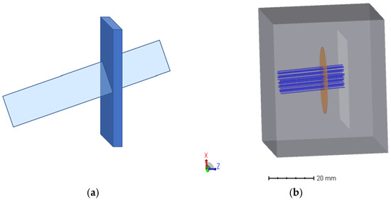
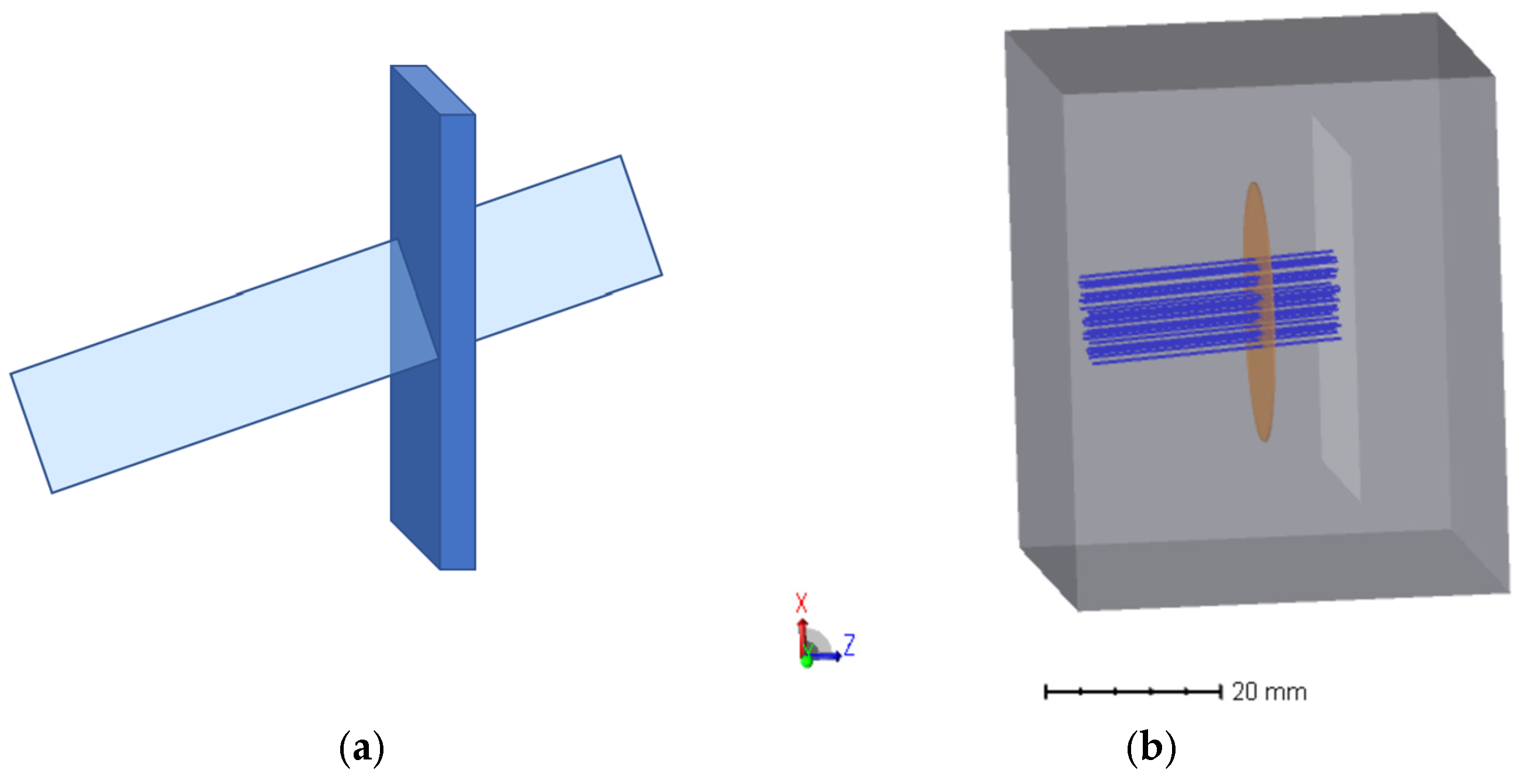
As stated in the paper “Etalon filters” by David M. Rust from The Johns Hopkins University Applied Physics Laboratory [19], the passband wavelength is also related to the tilt angle θ of the etalon in the optical path. Tilting the etalon shifts the passband toward shorter wavelengths. Meanwhile, the periodic shift also enables the FP etalon to exhibit identical peaks at different angles. We performed simulations on its transmittance characteristics by illuminating the FP with beams of the same wavelength at different angles. The laser wavelength was kept at 532.208 nm, and the incident light angle was adjusted in the XZ plane, as shown in Figure 9. The light intensity received by the detector at each angle was recorded, and the angle–transmittance curve was plotted.
Figure 9.
Schematic Diagrams (a) Schematic diagram of F-P etalon under oblique incidence; (b) schematic diagram of F-P etalon under oblique incidence in optical simulation software.
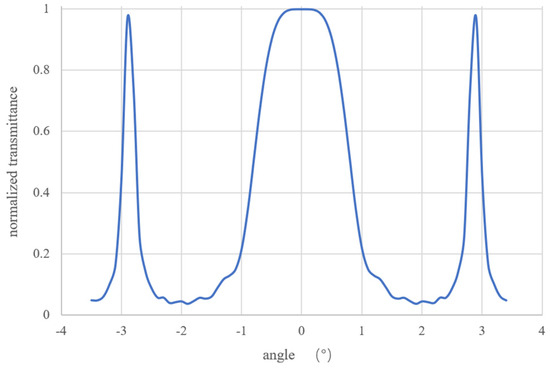
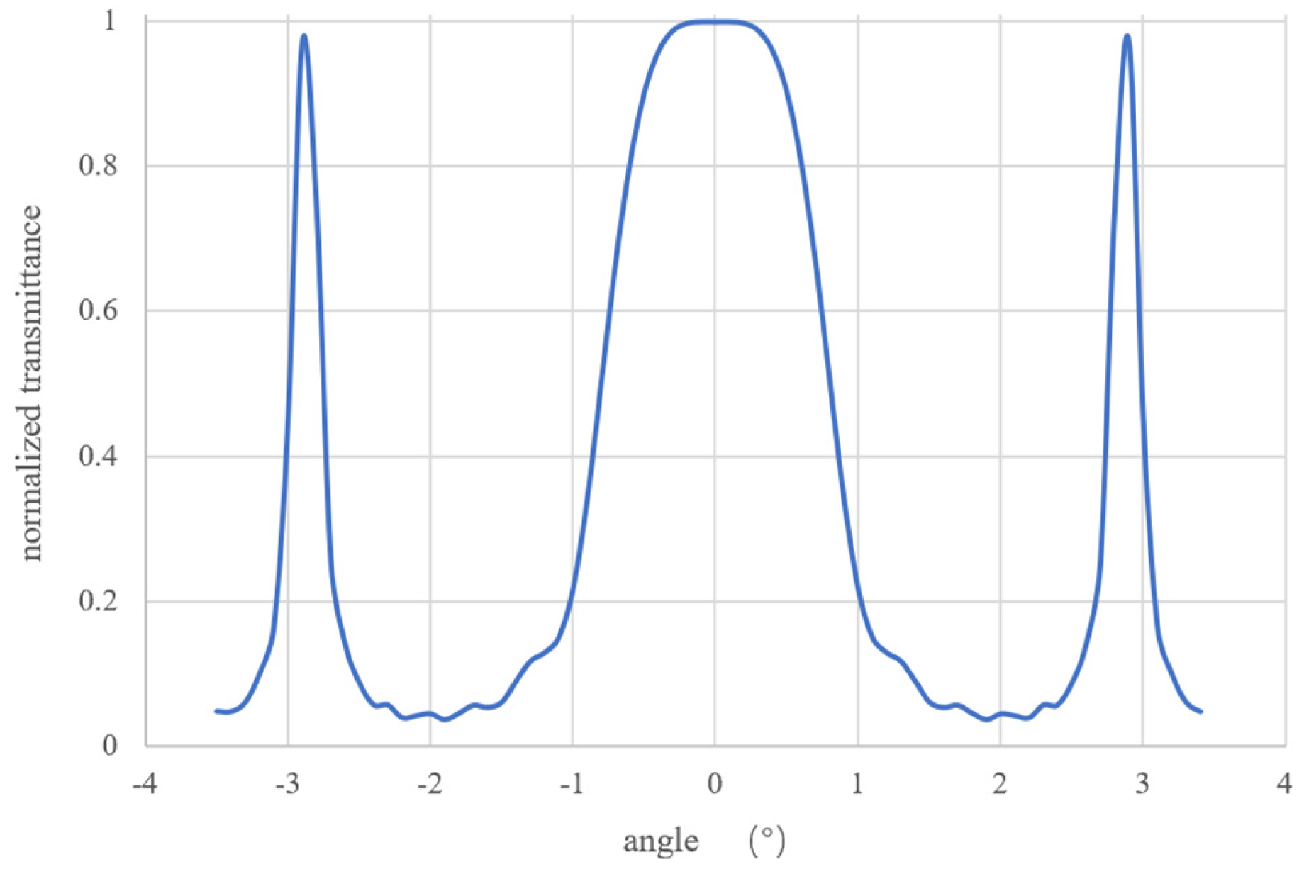
The simulation results show that the designed ultra-narrow F-P filter module has high transmittance not only in the central region of normal incidence (0°), but also symmetrically distributed high transmittance peak regions at symmetric angles other than 0°, as shown in Figure 10. Besides the central transmission interval with a bandwidth of ±1° centered at 0°, obvious transmission peaks with a bandwidth of 0.1 nm appear at ±2.9° in the curve, which is a key optical characteristic for realizing optical path multiplexing and improving light utilization efficiency. This symmetry characteristic facilitates the field-of-view design of the module and can be used to realize uniform reception and utilization of optical signals with different fields of view.
Figure 10.
Schematic diagram of normalized angle–transmittance curve.
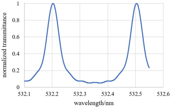
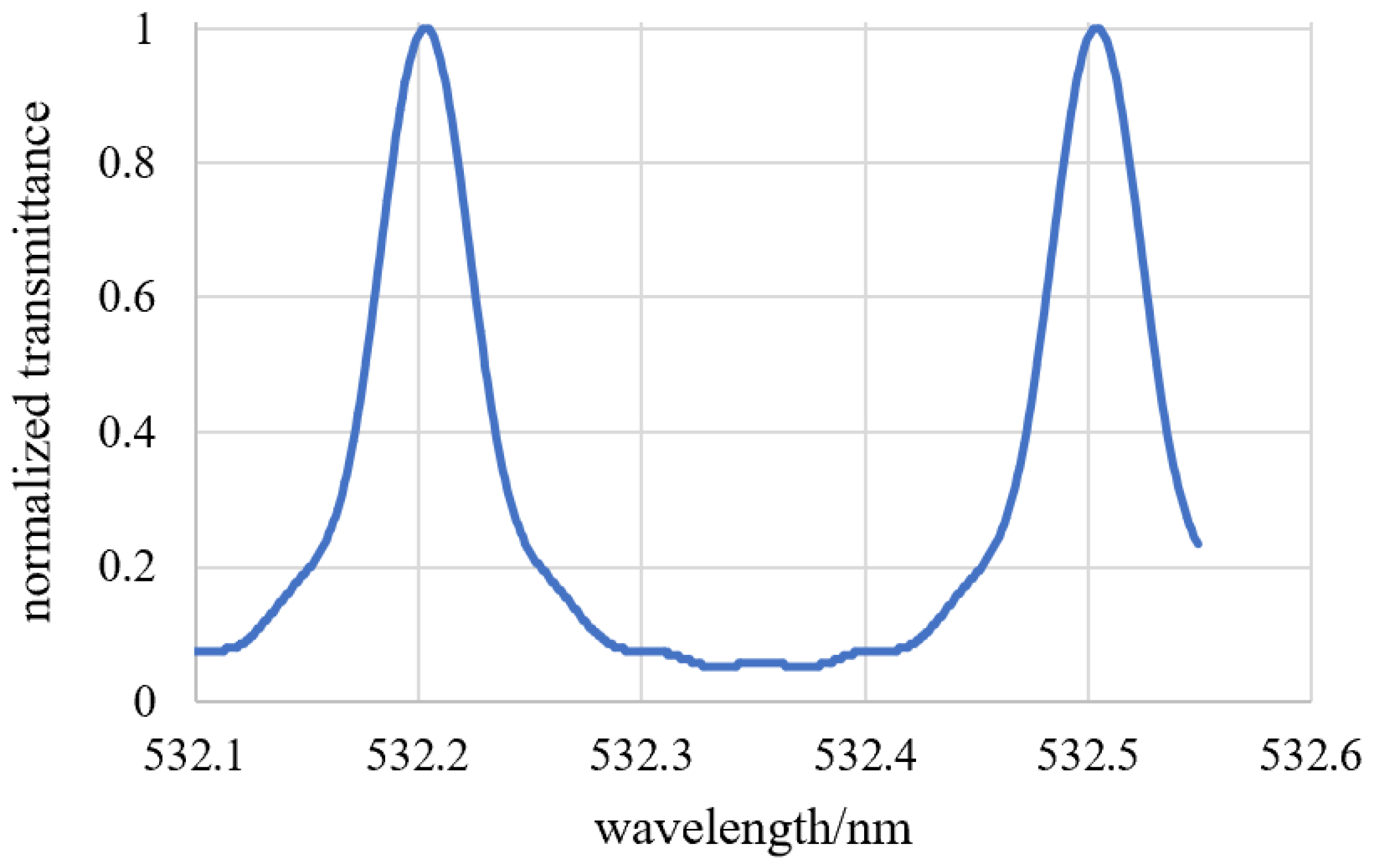
It can be seen from the angle–transmittance change curve that although all are peak intervals, the normalized transmittance value at oblique incident angles is slightly less than 1, that is, the position of the transmission peak has a slight drift, which is considered to be caused by the change in phase difference due to the change in incident angle, but the drift is small. Under the incidence of ±2.9°, the peak positions of transmittance at different wavelengths are 532.204 nm and 532.504 nm respectively. The peak interval of the left peak is still within the index requirement of ±0.1 nm, meeting the application conditions, as shown in Figure 11.
Figure 11.
Schematic diagram of normalized transmittance under ±2.9° incidence.
Within the allowable error range of engineering laser frequency selection, non-normal incidence has no effect on the frequency selection performance of the module. At the same time, the linewidth of the transmission peak at each angle maintains the original frequency selection characteristic. The simulation results reveal that there are many usable angles for the F-P filter module. Based on this characteristic, an optical system is used to convert optical signals of different fields of view into parallel incident light at different angles to construct a high-utilization laser frequency-selective ultra-narrow F-P filter module, enabling the F-P module to receive and utilize optical signals at multiple angles simultaneously and realize multi-angle multiplexing of light. The simulation theoretically ensures the feasibility of the high-utilization design.
4. High-Utilization Ultra-Narrow F-P Filter Module
If only the central angle in the above-mentioned angular transmittance diagram is adopted for the collimated optical path of the traditional FP filter module, the edge angles cannot be utilized. Aiming at the problem of low optical utilization efficiency of the traditional F-P filter module, based on the simulation results of laser frequency selection performance, this paper proposes the core design concepts of field-angle conversion and optical path multiplexing.
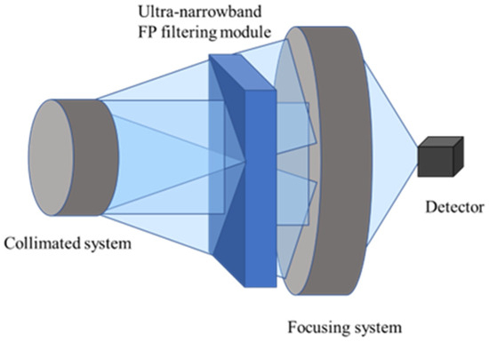
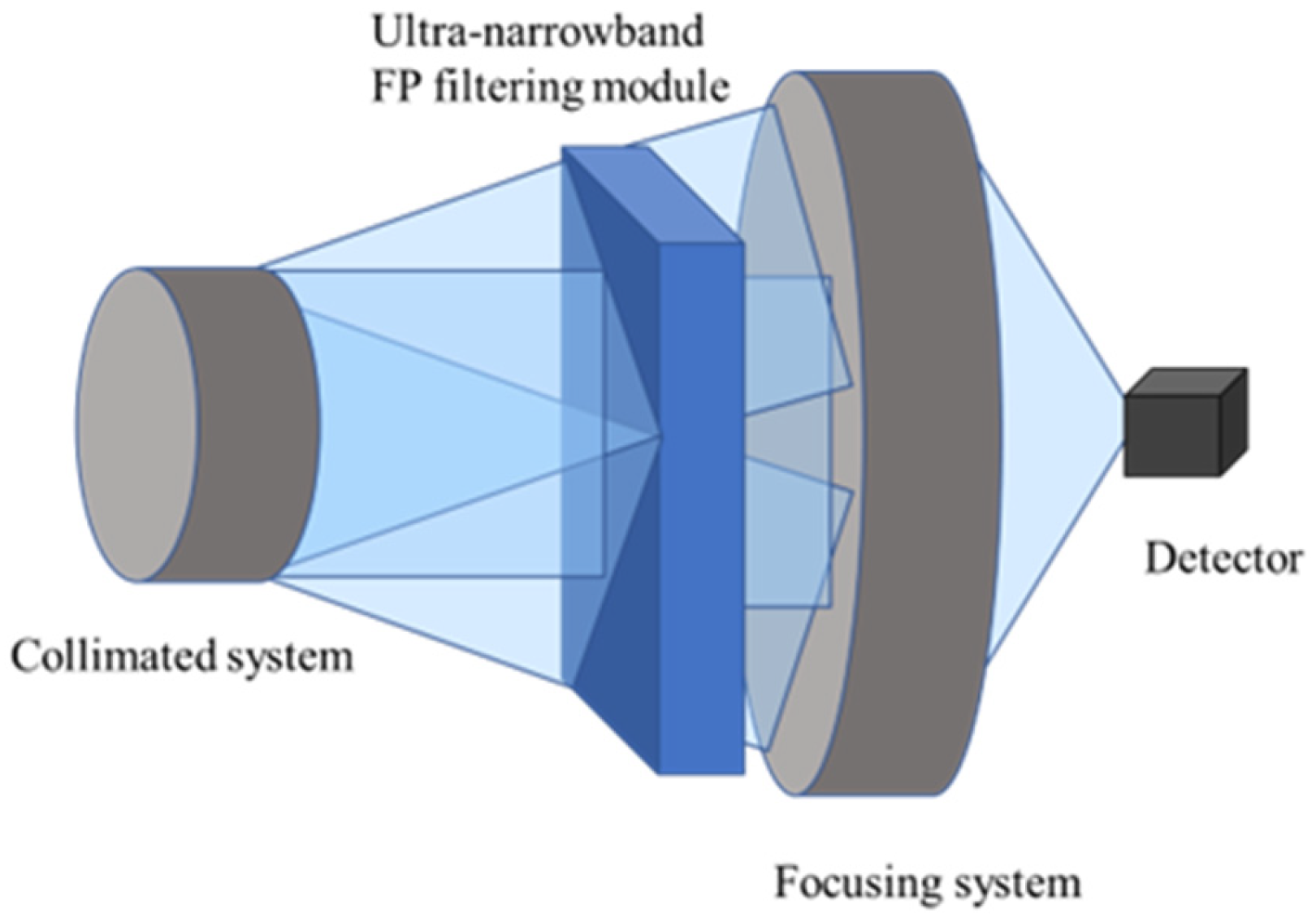
The high-efficiency ultra-narrow F-P filter module is an integrated optical system, which is mainly composed of four parts: parallel incident light, ultra-narrow F-P filter, focusing system and detector. The overall optical path design of the module is shown in Figure 12.
Figure 12.
Optical path diagram of the design scheme for the high-utilization ultra-narrow F-P filter module.
4.1. Optical Path Acquisition Design
We performed simulations in sequential mode to analyze the ray collection efficiency of the FP system’s acquisition optical path, verifying the feasibility of optical signal convergence. In non-sequential mode, we analyzed the spectral characteristics of light collected by the FP etalon, verifying that its peak position remains stable at specific angles and meets engineering requirements.
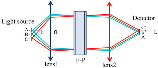
Taking the detection requirement of laser energy point variation as an example, since the acquired signal contains stray light that needs to be filtered, we designed a high-utilization ultra-narrow FP filter module receiving system. External signals are collected and converged onto the source plane, forming three points A, B, and C (symmetric to A with respect to the optical axis). The F/# of points A, B, and C is 10, the separation distance between A and B is h = 3 mm, and the three points are arranged linearly on the focal plane with 3 mm spacing.
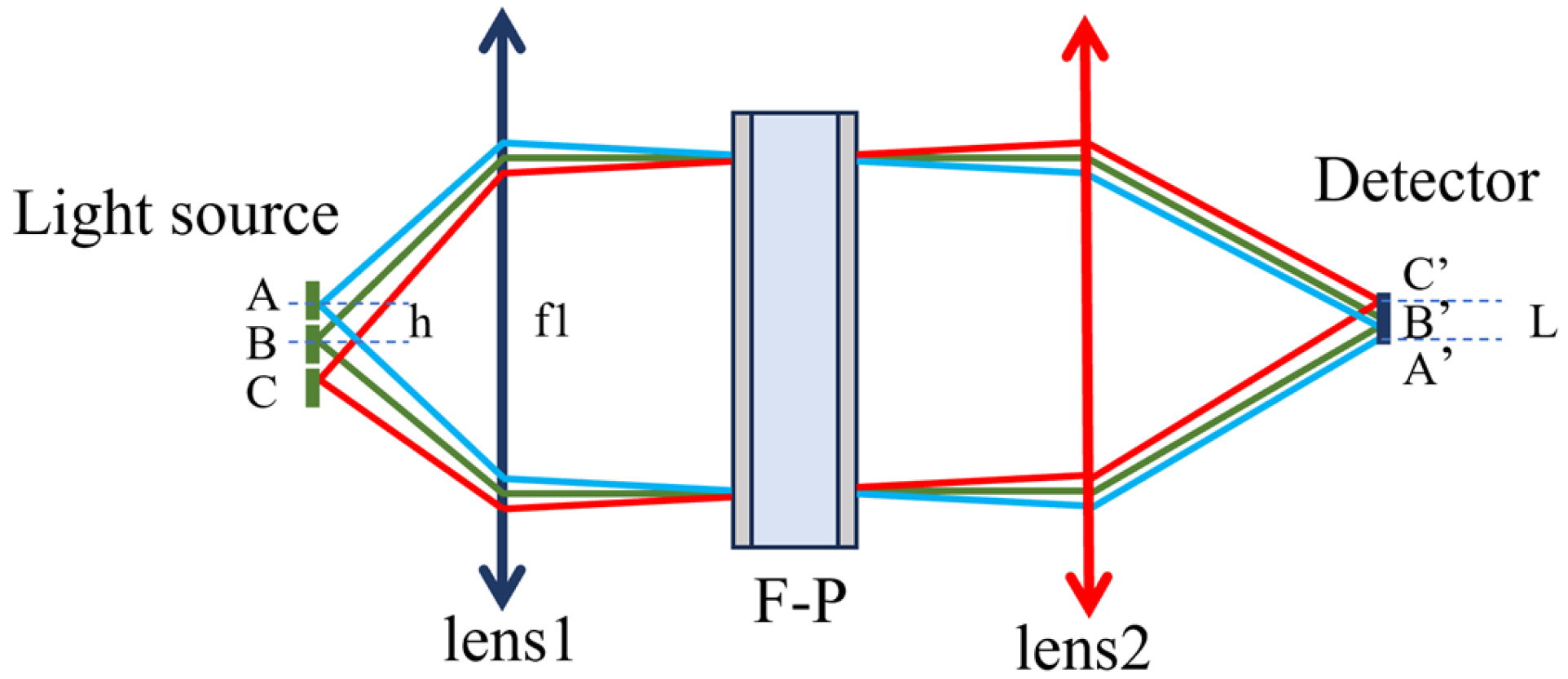
To detect energy variations at the three points, the point sources must be collimated into parallel beams before entering the FP module. Thus, a collimating optical system is designed. The schematic diagram of the optical system for laser spot energy detection is shown in Figure 13.
Figure 13.
Schematic diagram of the optical system for laser spot energy detection.
The numerical aperture is given by NA = 1/(2·F/#) = 0.05. Without vignetting, the focal length should satisfy f ≥ Δx/NA = 3 mm/0.05 = 60 mm, and the beam diameter is D = 2NAf = 6 mm. The parallel optical path in front of the F-P is approximately 12 mm, so the collimation length must be greater than 12 mm. In the collimation system design, suitable commercial lenses or custom-designed optical systems can be selected. As shown in the simulations in Section 3, the angles θ between the three parallel beams between Lens1 and the F-P and the optical axis should be −2.9°, 0°, and 2.9°. According to the imaging relation f = h/tanθ, a lens group with a focal length of 60 mm and an aperture larger than 12 mm is adopted to meet the collimation and incident angle requirements.
A cemented lens composed of a positive lens (crown glass) and a negative lens (flint glass) is used to reduce spherical aberration. Lens1 is optimized in sequential mode to ensure the output rays are parallel. The final parameters of the lens system are listed in Table 1.
Table 1.
Collimated cemented lens.
The F-P etalon does not change the propagation direction. Behind the F-P device, a focusing lens is used to converge the rays so that the dimension L in Figure 1 is smaller than the detector target surface. When an APD detector is used, the target size can be set to 3 mm. The curvature and thickness of the lens group are optimized so that the value of L is less than 3 mm. The final parameters of the converging cemented lens are listed in Table 2. The final lens system is shown in Figure 14.
Table 2.
Converging cemented lens.
Figure 14.
Schematic diagram of lens system.
The optical utilization efficiency of the proposed high-efficiency ultra-narrow F-P filter module is mainly improved through the following two aspects, which cooperate with each other to form an organic whole and ultimately achieve a significant enhancement in optical utilization efficiency. Optical principle aspect: The designed core F-P filtering module exhibits symmetric high-transmittance peaks at multiple angles under non-normal incidence, which provides an optical foundation for multi-angle light utilization and breaks through the conventional design limitation that only normal incident light is used in traditional modules. Optical design aspect: Through the image height–angle conversion function of the optical system, optical signals from different fields of view are accurately converted into parallel incident beams matching the high-transmittance angles, so that optical signals from each field of view can be incident on the filtering core module at high-transmittance angles, ensuring effective utilization of optical signals.
Compared with traditional Fabry–Pérot (F-P) filter modules that only adopt the normal incidence mode, the high-efficiency F-P filter module designed in this paper enables simultaneous utilization of multi-angle incident light, which significantly broadens the receiving range and effective utilization interval of optical signals.
On the premise that the core parameters of the F-P etalon remain unchanged, the receiving range of optical signals is effectively expanded, thereby significantly improving the performance of the F-P etalon.
4.2. Simulation of Multi-Angle Multiplexing Component
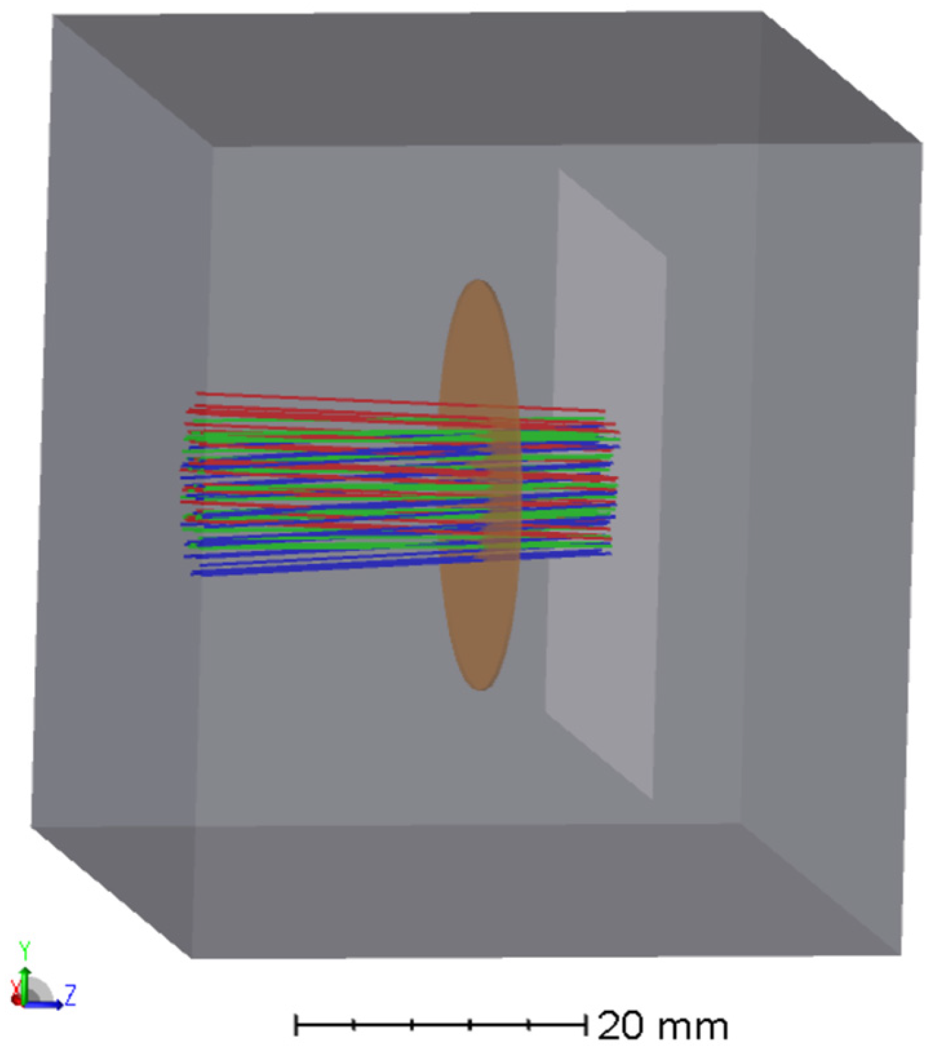
To verify the peak position of the high-utilization laser frequency-selective ultra-narrow F-P filter module and predict its practical test performance, simulations were carried out in non-sequential mode for multi-angle parallel light incident on the FP assembly. Three parallel beams were used to simulate the rays at three angles exiting Lens1 in sequential mode. The incident power of the three parallel beams was set to unity, with angles in the YZ plane set to 0°, 2.9°, and −2.9° to simulate the superposed incidence of the beams, as shown in Figure 15. The wavelength frequency-selective characteristic curve of the module under this operating condition was thus obtained.
Figure 15.
Schematic diagram of F-P etalon under incidence at three angles (0°, 2.9°, −2.9°).
5. Simulation Results
5.1. Feasibility of Signal Acquisition
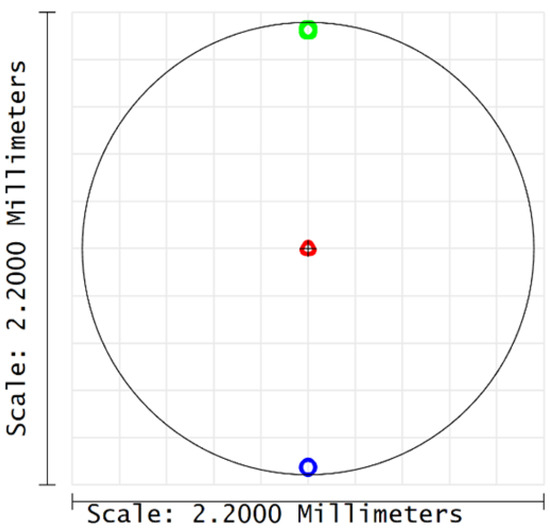
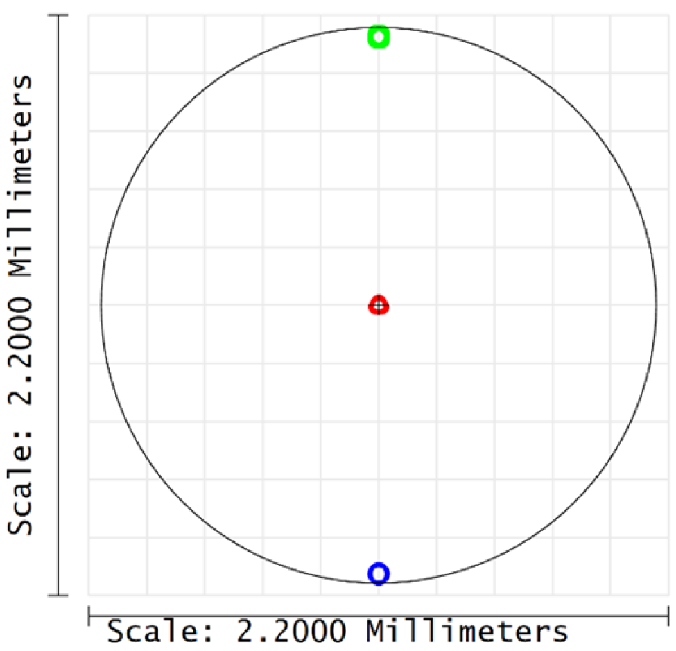
In the acquisition optical path, the maximum distance of the focused light spot received by the optical system is less than 2.2 mm, as shown in Figure 16. The photosensitive area of a common APD is 3 mm, so the focusing module meets the system requirements for signal acquisition.
Figure 16.
Schematic diagram of system focusing results.
5.2. Stability of Multi-Angle Filtering Peaks
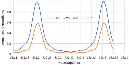
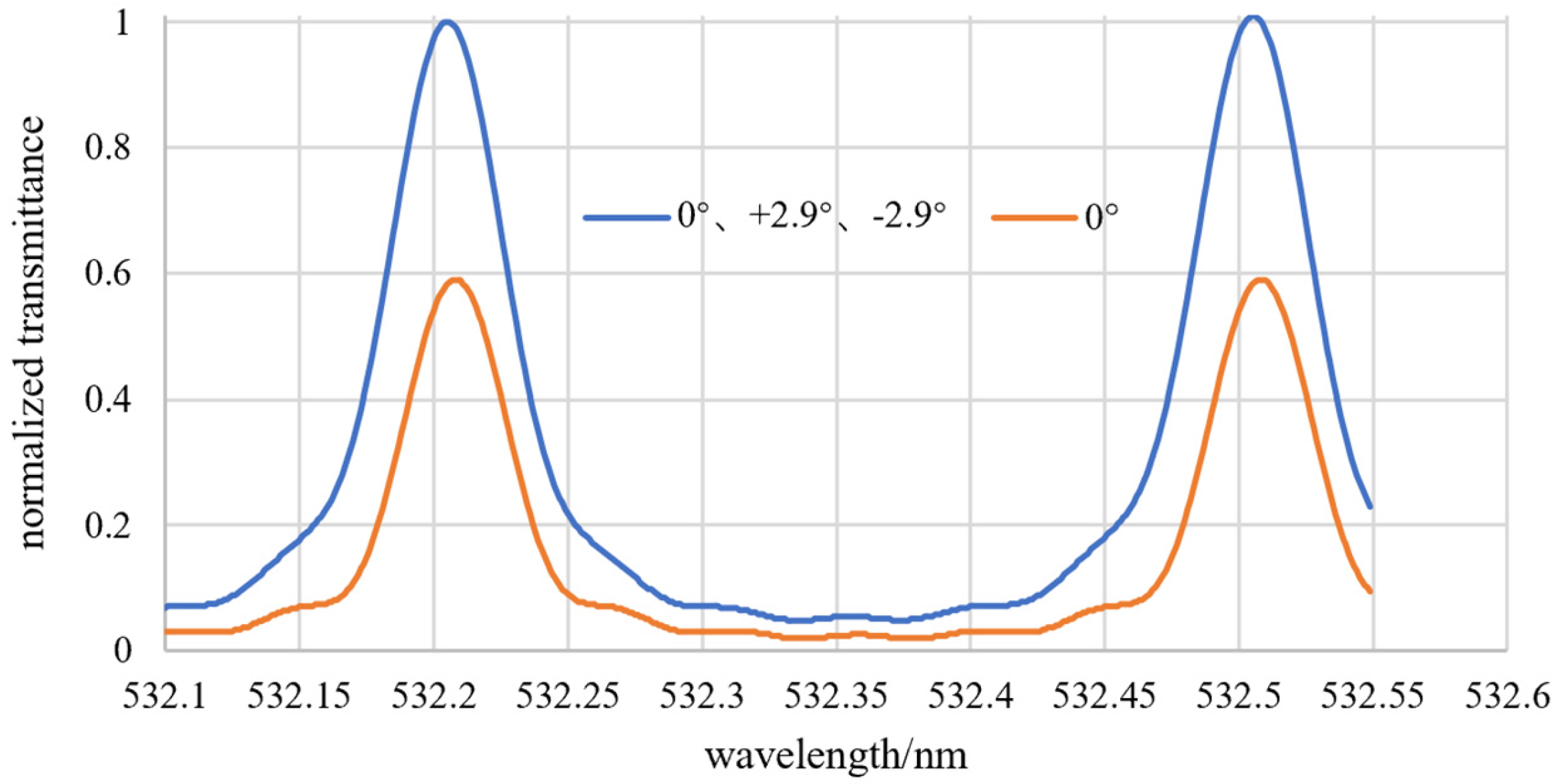
The simulation results of spectral characteristics verified in non-sequential mode are shown in Figure 17. The peak wavelengths of the superposed incident light are 532.208 nm and 532.508 nm respectively, with a free spectral range of 0.3 nm, and the frequency-selective characteristic at the central wavelength of the module remains stable. Although the transmission bandwidth is slightly broadened, it is still controlled within 0.06 nm, which falls within the allowable range for engineering applications and meets the design requirements of ultra-narrow band filtering.
Figure 17.
Schematic diagram of frequency-selective characteristics of normalized superposed signals and single signal.
After normalization, the normalized energy of the superposed incident light reaches 1.67 times that of single-angle incidence, improving the effective utilization efficiency of optical signals.
The above simulation and test results verify the rationality and reliability of the core performance of the high-utilization ultra-narrow band F-P filter module. It is confirmed that the multi-angle superposed incidence scheme can effectively improve the utilization efficiency of F-P frequency-selective signals in the system. This provides solid simulation support and an effective reference for the subsequent engineering implementation, structural optimization, and performance iteration of the module.
6. Discussion
Aiming at the core pain point of low light utilization efficiency of traditional F-P filters in engineering applications, this paper systematically carries out relevant research on laser frequency-selective ultra-narrow F-P filter modules. First, the core principle of laser frequency selection of the module is deeply studied, on the basis of which an optical simulation system is built to complete the simulation analysis of the frequency selection characteristics and angle transmission characteristics of the module. Then, the core design concept of “field-of-view-angle conversion and optical path multiplexing” is proposed, the integrated structural design of the high-utilization ultra-narrow F-P filter module is completed, and the overall scheme of the high-utilization laser frequency-selective ultra-narrow F-P filter module is constructed, realizing the organic combination of ultra-narrow band filtering function and optical signal multiplexing. Compared with cascaded FP etalons operating in normal incidence, the multiplexed FP module proposed in this paper exhibits higher transmittance and features a simpler system architecture with only one FP component. Compared with volume Bragg gratings (VBG), this multiplexed FP module features higher accuracy, with its linewidth controlled within 0.06 nm, which is superior to the 0.1–0.5 nm linewidth of VBG. It also has a wider angular acceptance range, effectively overcoming the drawback of VBG where diffraction efficiency drops sharply when the incident angle deviates slightly from the Bragg angle, making it more suitable for fixed-point laser signal monitoring scenarios. Compared with MEMS tunable FP filters, the multiplexed FP module in this paper does not require a complex precision control system, avoiding the defects of easy cavity length deformation under external force and weak resistance to vibration and shock. It achieves high accuracy in wavelength peak position, while maintaining more stable performance and a simpler system structure. The module realizes a high transmittance of 68–79% and theoretically provides more than double the energy gain. At the same time, it broadens the angular acceptance range (±0.5°, 2.9° ± 0.1°, and −2.9° ± 0.1°) and reduces system complexity. Overall, it shows superior performance in various aspects compared with other existing filter modules. The performance comparison is listed in Table 3.
Table 3.
Type and performance comparison.
The application effect of multi-angle signal superposed incidence is verified by simulation experiments, which provides a solid theoretical support for the optical path multiplexing design of the module and the improvement of light utilization efficiency. The research results not only provide a brand-new technical solution for laser frequency selection technology in the fields of aerospace precision measurement, remote sensing detection, navigation and positioning, and have important engineering application value, but also offer a feasible new idea and technical reference for the performance optimization and upgrading and application scenario expansion of other interference optical devices.
Author Contributions
Conceptualization, L.W. and Y.S.; methodology, Y.S. and L.W.; software, L.W.; validation, L.W., L.D. and Y.W.; formal analysis, Y.S., T.L. and L.W.; investigation, L.W.; resources, T.L., J.Y. and J.Z.; data curation, L.W., J.Y. and Y.W.; writing—original draft preparation, L.W.; writing—review and editing, L.D.; visualization, L.W. and T.L.; supervision, Y.S.; project administration, J.Z.; funding acquisition, J.Z. All authors have read and agreed to the published version of the manuscript.
Funding
This research received no external funding.
Institutional Review Board Statement
Not applicable.
Informed Consent Statement
Not applicable.
Data Availability Statement
The original contributions presented in this study are included in the article. Further inquiries can be directed to the corresponding authors.
Conflicts of Interest
Author Jinhui Yang was employed by the company China National Building Materials Group Academy. The remaining authors declare that the research was conducted in the absence of any commercial or financial relationships that could be construed as a potential conflict of interest.
References
- Tang, T.J.; Yang, J.K.; Fu, R.M.; Sun, L.; Sun, X.; Wang, Y.Z.; Song, Z.Q. Optical Design Used in Multi-beam LiDAR for Monitoring of TECIS. Spacecr. Recover. Remote Sens. 2022, 43, 36–49. [Google Scholar] [CrossRef]
- Shi, Z.C.; Zhang, S.C.; Chi, D.N.; Ding, J.; He, X.; Xu, P. Design Technology on the Optical Remote Sensing System for High-Orbit Satellite Observation in the Ocean and Coastal Zone. Spacecr. Recover. Remote Sens. 2025, 46, 86–95. [Google Scholar] [CrossRef]
- Yang, T.; Xu, P.M.; Fu, Z.H.; Duan, P.; Li, S.; Hu, B.; Wang, J.; Zhang, K. Design and Implementation of New Generation Ocean Color and Temperature Scanner System. Spacecr. Recover. Remote Sens. 2025, 46, 49–62. [Google Scholar] [CrossRef]
- Cheng, L.; Ding, L.; Zhang, Z.R. A CO2 Detection System Based on Broadband Light Source and FP Cavity Filter. Semicond. Optoelectron. 2020, 41, 268–272. [Google Scholar] [CrossRef]
- Wang, Y.Q.; Xu, Y.R.; Chen, P.; Liang, K. Remote Sensing of Seawater Temperature and Salinity Profiles by the Brillouin Lidar Based on a Fizeau Interferometer and Multichannel Photomultiplier Tube. Sensors 2022, 23, 446. [Google Scholar] [CrossRef] [Scilit] [PubMed]
- Dai, C.J.; Dong, X.F.; Zhou, Q.Q.; Xu, D.; Tao, S.; Li, Z.; Wan, C.; Yang, W.-X. Narrowband Spectral-Selective Wavefront Shaping via a Fabry-Perot-Type Blazed Metagrating. J. Light. Technol. 2025, 43, 1322–1327. [Google Scholar] [CrossRef] [Scilit]
- Li, C.Z.; Wang, P.Y.; Long, M.Q.; Xu, Y.; Han, R.; Jia, T. Precision machining of ITO thin films by femtosecond laser pulse trains based on Fabry-Perot cavity. Acta Photonica Sin. 2025, 54, 33–46. [Google Scholar] [CrossRef] [Scilit]
- Zhao, Y.M.; Li, F.; Pan, C.; Li, J.; Yu, Y.; Li, L. Design of Atmospheric Detection LiDAR System Based on Spaceborne Dual-Wavelength Polarization Detection. Chin. Space Sci. Technol. 2023, 43, 150–159. [Google Scholar] [CrossRef]
- Cong, R.; Zhou, S.; Chen, G.; Cai, Q.; Jiang, L.; Liu, D. Influence of Reflective Phase Shift on Filtering Characteristics of Tunable Fabry-Pérot Filter with Small Cavity Length. J. Infrared Millim. Waves 2021, 40, 44–49. Available online: https://journal.sitp.ac.cn/hwyhmb/hwyhmbcn/article/html/2020120 (accessed on 13 April 2026).
- Lin, Y.Q.; Xia, H.; Zhang, Z.R.; Sun, P.; Wu, B.; Li, Z.; Cai, Y. Research on High-precision Real-time Wavelength Monitoring Method Based on Fabry-Perot Etalon. Chin. J. Quantum Electron. 2025, 42, 187–195. [Google Scholar] [CrossRef]
- Zhu, Y.Y.; Guan, X.Y.; Yu, P.Q.; Liu, Q.; Jia, Q.; Wu, J.; Li, C.; Li, Z.; Wang, S. High-performance spectral polarization splitter integrating subwavelength grating and Fabry-Perot filter. J. Infrared Millim. Waves 2024, 43, 179–186. [Google Scholar] [CrossRef]
- Li, C.W.; Deng, Q.; Li, C.; Wu, D.C.; Liu, D.; Wang, Z.Z. Development of Pressure-tuned Narrowband Filter and Its Application in Iron Resonance Fluorescence LiDAR. Chin. J. Quantum Electron. 2025, 42, 196–205. [Google Scholar] [CrossRef]
- Li, Y.T.; Xie, P.H.; Xu, J.; Lv, Y.; Zhang, H.; Zhang, Z.; Ling, L.; Xing, L. In situ measurement of CO2 based on Fabry-Perot interferometer. J. Atmos. Environ. Opt. 2025, 20, 739–751. [Google Scholar] [CrossRef]
- Hu, Y.H. Research on FP Etalon for Imaging. Ph.D. Thesis, Changchun University of Science and Technology, Changchun, China, 2010. [Google Scholar]
- Xu, J.Q.; Wang, Y.Q.; Xu, Y.R.; Liang, K.; Zheng, Y.C.; Su, Y.; Zhang, J.H. Research Progress of Ocean Environmental Laser Remote Sensing Based on Brillouin Scattering. Infrared Laser Eng. 2021, 50, 202110. [Google Scholar] [CrossRef] [Scilit]
- Saleh, A.; Mekhrengin, M.; Dönsberg, T.; Kääriäinen, T.; Genoud, G.; Toivonen, J. Mid-infrared Hyperspectral Sensor Based on MEMS Fabry-Pérot Interferometer for Stand-off Sensing Applications. Sci. Rep. 2022, 12, 19392. [Google Scholar] [CrossRef] [Scilit] [PubMed]
- Ji, H.C.; Xie, P.H.; Xu, J.; Li, A.; Hu, Z.; Huang, Y.; Tian, X.; Li, X.; Ren, B.; Ren, H. Measurement of Atmospheric CO2 Based on Tunable Fabry-Perot Interferometer. Acta Opt. Sin. 2021, 41, 137–147. [Google Scholar] [CrossRef] [Scilit]
- Lyu, Y. Research on Single-Photon Detection Laser Ranging Based on FP Etalon Filtering. Master’s Thesis, East China Normal University, Shanghai, China, 2019. [Google Scholar]
- Rust, D.M. Etalon Filters. Opt. Eng. 1994, 33, 3342–3348. [Google Scholar] [CrossRef] [Scilit]






Disclaimer/Publisher’s Note: The statements, opinions and data contained in all publications are solely those of the individual author(s) and contributor(s) and not of MDPI and/or the editor(s). MDPI and/or the editor(s) disclaim responsibility for any injury to people or property resulting from any ideas, methods, instructions or products referred to in the content. |
© 2026 by the authors. Licensee MDPI, Basel, Switzerland. This article is an open access article distributed under the terms and conditions of the Creative Commons Attribution (CC BY) license.