


Abstract
Nano-tweezers, especially those based on photonic crystals and plasmonic structures, are powerful tools for trapping, manipulating, or accelerating nano-sized objects. However, the precise control of the inter-distance between trapped nanoparticles has rarely been considered. In this paper, we propose a mirror-symmetric optical conveyor belt, in which each unit contains three graded nano-slots. Through the optimized design of spacing between these nano-slots, the structure generates multiple trapping centers, enabling wavelength-selective control over trapping positions. The results show that, through dynamically shifting excitation wavelengths, the programmable bidirectional optical manipulation of nanoparticles can be achieved. Also, the inter-distance between trapped particles can be tuned with subwavelength precision. The proposed structure provides a versatile solution for lab-on-a-chip systems, especially for systems aiming to study the interactions between objects.
1. Introduction
Since the first observation of optical trapping, it has attracted significant attention [1]. The contactless nature of optical trapping has inspired extensive research in physics [2,3], nanoscience [4,5], biology [6,7,8], and other fields [9,10]. However, conventional optical tweezers face challenges when applied for trapping nanoscale objects, as the gradient force diminishes rapidly [11]. Recent advancements demonstrate that nano-tweezers are an effective method for manipulating, accelerating, or trapping nano-sized objects, which overcomes the diffraction limit [12,13]. Moreover, the photonic and plasmonic nanostructures, with their ability to efficiently confine and enhance electromagnetic fields at subwavelength scales [14,15,16,17], have significantly advanced the manipulation of nanoscale objects [18,19]. Plasmonic nano-tweezers are a powerful platform for sub-diffraction-limited manipulation, enabling precise trapping, transporting, and acceleration of nanoscale objects [20,21]. Examples of designed plasmonic nano-tweezers include plasmonic nanopores [22,23], double nanohole plasmonic structures [24,25], and plasmonic antennas [26,27]. Due to the strong interaction between light and these structures, nanoscale particles can be stably trapped using low-power light sources [28].
The controlled transporting of multiple nanoparticles becomes a critical challenge in the field of optical manipulation, which is far more difficult than trapping multiple nanoscale particles [29,30]. Typically, the plasmonic nanotweezers can generate highly enhanced and tightly confined electromagnetic hotspots. Current research also shows the capability to simultaneously trap multiple nanoparticles [31,32,33]. Although plasmonic nanostructures enable the trapping of low-power nanoparticles, the transport efficiency of the trapped particles remains low due to the tiny trapping volume and the very limited hotspot area [34]. In recent years, the dynamic hotspots’ position has been controlled by rotating the polarization or tuning the wavelength of incident light, and target particles can be sequentially transported between different trapping sites [35]. In recent years, nanophotonic waveguides have shown strong capabilities in tailoring optical forces. They enable long-range optical transportation, which greatly broadens the territory of optical manipulation. Several long-distance optical transporting platforms based on a nanophotonic waveguide have been proposed. For instance, F. Ye et al. designed a thermally tunable standing-wave array that enables precise manipulation of polystyrene beads with a size of several hundred nanometers [36]. They successfully performed standard single-molecule-level experiments, stretching DNA molecules and measuring force-extension relations. Moreover, this platform demonstrated nm-precision relocation of the trapping centers, which is achieved by adjusting the phase difference between two counterpropagating waves in the nanophotonic waveguide. However, optical transporting is limited to relatively large particles. For nanoscale particles, the large mode volume of a standing wave (with a unit trapping zone on the order of half a wavelength) results in poor transport localization. In another approach, T. Sneh et al. utilized integrated optical phased arrays, demonstrating a novel mechanism for integrated optical tweezers [37]. This method enables optical trapping and manipulation of cells at 5 mm above the chip surface, effectively protecting both the chip and the samples from contamination. The researchers achieved micrometer-level flexible control of optical fields via wavelength sweeping. Despite its excellent performance in micromanipulation, this method still faces challenges in achieving nanometer-scale displacement accuracy for nanoparticles. Achieving precise control over the separation of trapped nanoparticles remains a challenge, especially for the small nanoparticles used in this study (with radii of 10–25 nm). The mode volume is typically large relative to the particle size. As a result, two particles tend to be trapped within the same hotspot rather than at distinct sites, making it difficult to precisely control their inter-distance. The research on dynamically controlling the inter-distance between trapped nanoparticles remains limited. In this paper, we primarily address two challenges: transporting nanoscale particles and precisely tuning their inter-distance. By slot modes in a plasmonic nanostructure rather than in photonic cavities, both optical transporting and precise inter-distance control of nanoscale particles are successfully achieved.
Here, we present a bidirectional nano-optical conveyor belt using a multiple plasmonic slot array. The structure supports three resonant modes. In the structure, the position of light localization can be tuned dynamically through altering the wavelength. The separation between the two trapped particles is also tuned by the trapping lasers. The position of the hotspot varies with the wavelength, and more importantly, by controlling the position of the hotspot, we can control where the trapping occurs. If we set the particular wavelength, such as the first mode, particles will be trapped in particular hotspots. When we change the illumination wavelength to the second mode, particles will be released first and then trapped again at the adjacent hotspots. And if we turn on the laser for the third mode, particles will jump to a further hotspot. By controlling the position of the hotpot, we control the movement of target particles. In this paper, particles can be directionally transported along a 1D trajectory, with a step size of 70 nm.
2. Materials and Model
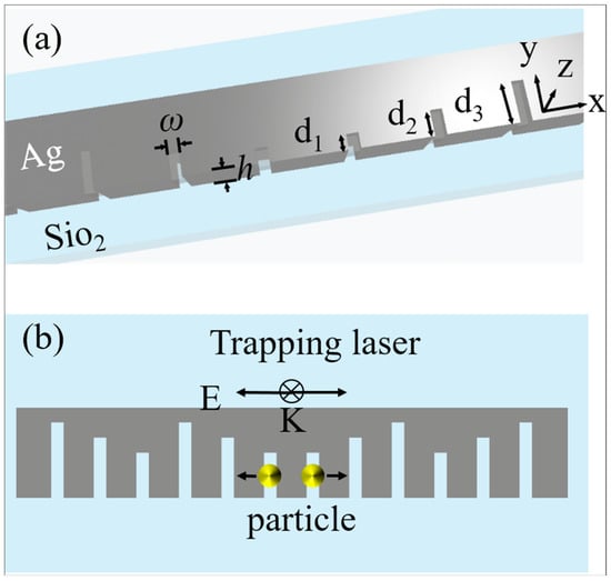
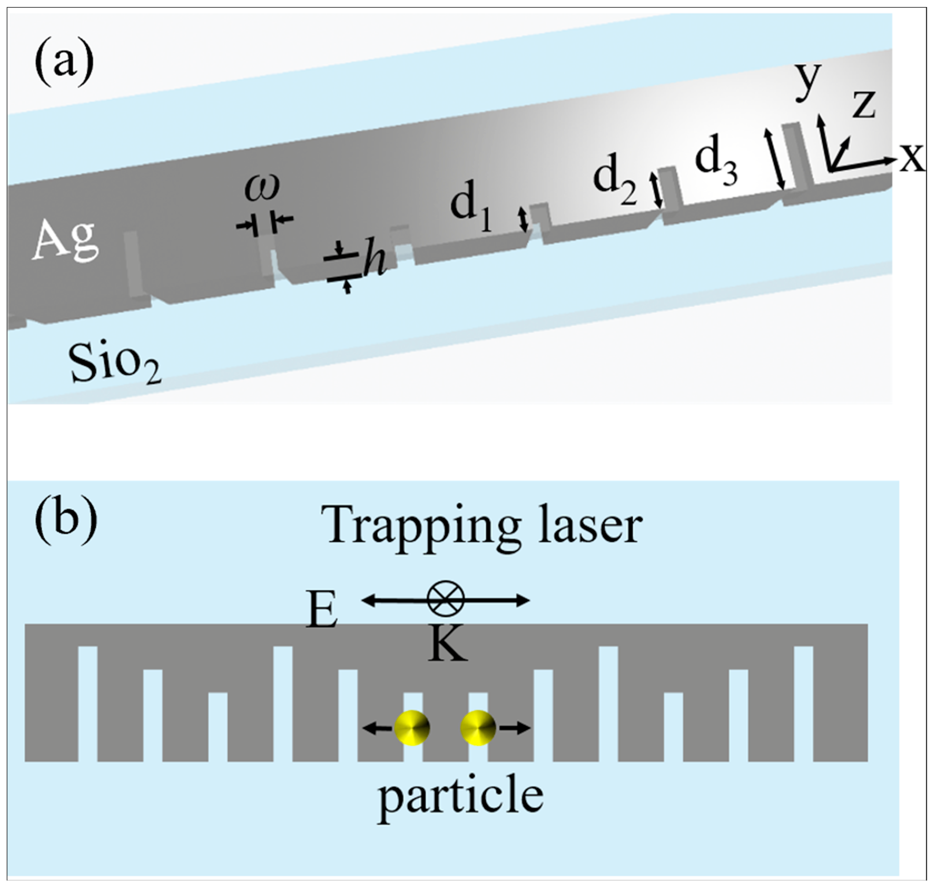
Figure 1 shows the schematic of the bidirectional nano-optical conveyor belt, which is formed of rectangular nanoslot cavities. The multiple equally separated nanoslots are arranged in a mirror-symmetric distribution, and the center-to-center distance between two adjacent nanoslots is L = 70 nm. The distance is optimized to have low crosstalk. The rectangular slot is a wavelength-selective structure; by varying its length, it can be designed to resonate at different wavelengths. Three nanoslots of different lengths (d1 = 30 nm, d2 = 50 nm, and d3 = 80 nm) are selected as a group to achieve the sustained optical transporting. The nanoslots are distributed with mirror symmetry, thereby enabling the precise adjustment of the separation between the trapped particles. The slot cavity array is embedded in the silver film, with a height of h = 50 nm. Furthermore, the width of the nanoslot is 10 nm, and the nanoslot array is arranged along the x direction. The entire system is immersed in water (refractive index nw = 1.33), and the x-polarized beam is incident on the surface along the −z direction.
Figure 1.
The operating principle and parameters of the bidirectional nano-optical conveyor belt. (a) Schematic and detailed parameters of the proposed nano-optical conveyor belt: a series of nanoslots with different lengths are embedded in the silver film. The height of the silver film is h. Three different lengths of nanoslots are named d1 to d3, respectively. The width of the nanoslots is w. (b) Principle of the setup. An x-polarized plane wave with the particular resonant wavelength λ1 is used to excite the gap mode in the nanoslot areas, and optical trapping will occur on the shortest slots. When the incident wavelength is tuned, the trapping samples will be transferred to the nearby nanoslots accordingly.
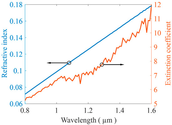
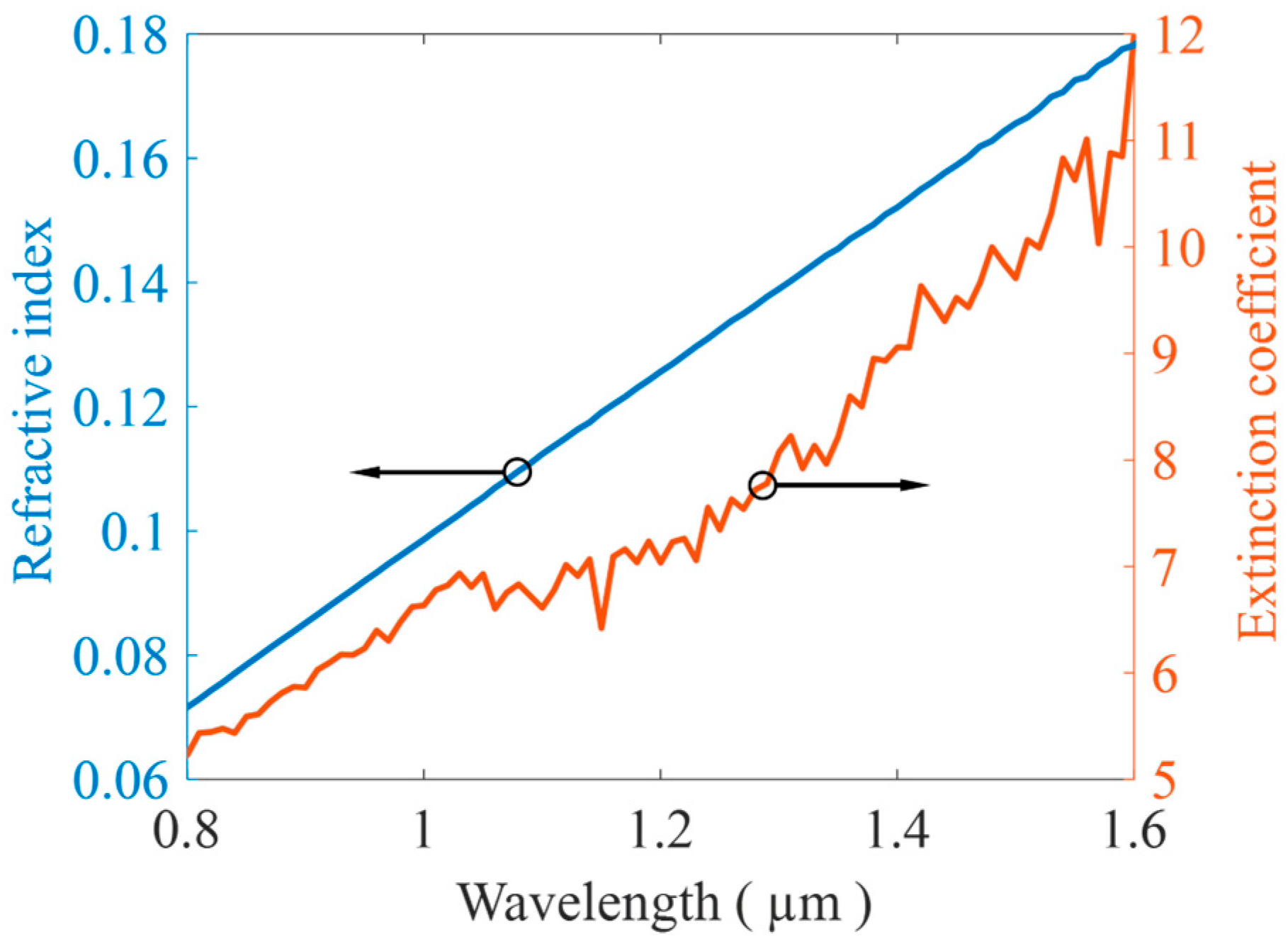
Furthermore, the material data of the silver is taken from reported data [38]. Figure 2 shows the refractive index and extinction coefficient of the silver layer for the incident wavelength between 800 and 1600 nm.
Figure 2.
Refractive index and extinction coefficient values for the 50 nm-thick Ag film.
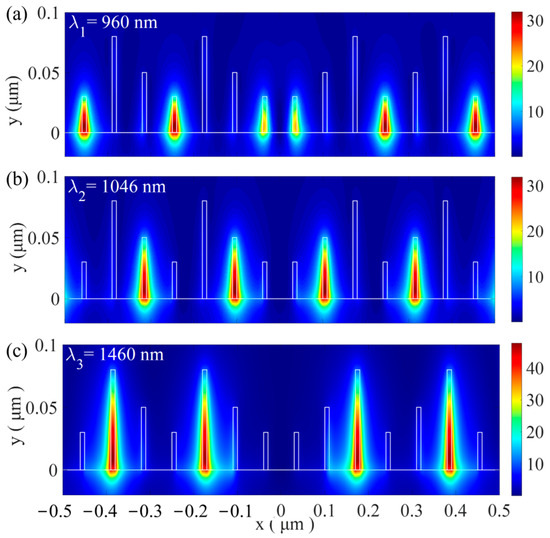
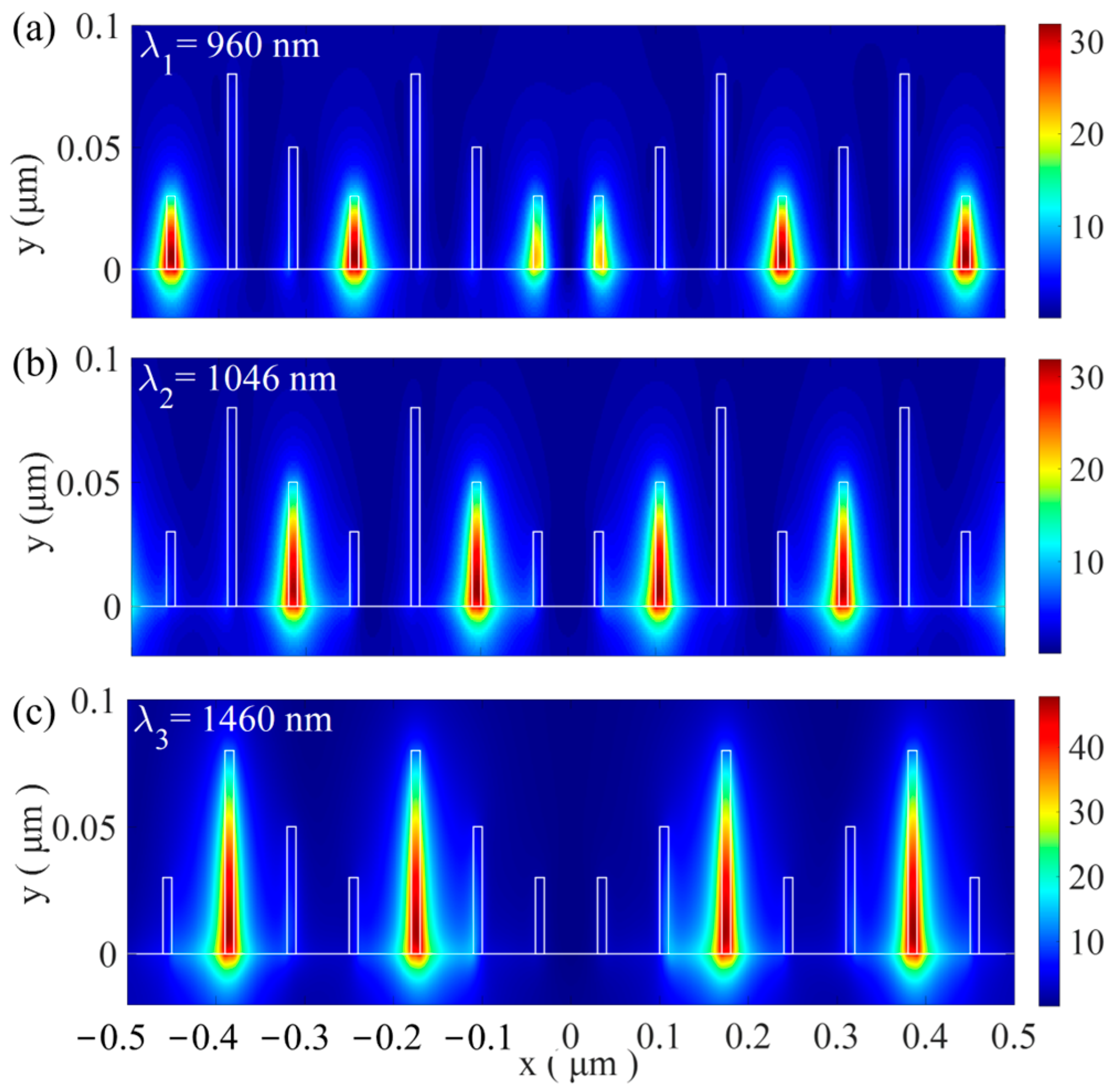
A laser beam polarized along the x-direction is used to efficiently excite the gap plasmon mode within the nanostructures. Using the finite-difference time-domain (FDTD) method, we calculate the electric field distribution at 5 nm above the surface of the optical conveyor belt (z = 55 nm), as shown in Figure 3.
Figure 3.
(a) The electric distribution of the xy cross-section view, 5 nm above the surface of the optical conveyor belt (z = 55 nm) for the first-order mode, (b) the second-order mode, and (c) the third-order mode.
The three resonant wavelengths for the first, second, and third modes are 960 nm, 1046 nm, and 1460 nm, respectively. All resonant modes exhibit significant field confinement in the slots. For the first mode, the electric field is concentrated at the shortest slots, while for the second and third modes, the hotspots shift to the medium-length and longest-length slots, respectively. It is confirmed that the structure supports wavelength-selective resonance fields, and this property allows for controlling where the optical trapping occurs by changing the wavelength.
The optical force exerted on the nanoparticle is evaluated using the Maxwell stress tensor (MST) integration method. And the time-average optical force is calculated by integrating the MST over a surface S enclosing the nanoparticle, which is described as
where T is the time-averaged Maxwell stress tensor (MST). The definition of T is
where and represent the relative permittivity and relative permeability of the medium surrounding the surface, respectively.
During the optical trapping process, particles undergo random Brownian motion. To suppress the Brownian motion, the trapping potential well depth should exceed 10 kBT, where kB is the Boltzmann constant and T is the absolute temperature. The trapping potential well exerted on the particle located at r0 is expressed as
3. Optical Trapping in the Nano-Optical Conveyor Belt
3.1. The Optical Nano-Trapping in the Transverse Direction
We have calculated the trapping force and trapping wells exerted on a gold nanoparticle near the nano-optical conveyor belt. The radius of the nanoparticle is rp = 20 nm, and the refractive index data were taken from the CRC handbook. The particle is placed 10 nm above the nanostructure surface. The linearly polarized plane wave is incident from the top along the −z direction with an intensity of 10 mW. The ambient temperature is taken as T = 300 in the trapping well calculations. In the Cartesian coordinate system shown in Figure 1, the origin (x = 0, y = 0, and z = 0) is defined as the central point of the Ag-SiO2 interface. We calculate the optical force on the nanoparticle as it approaches the structure along the +x axis (y = 10 nm, z = 55 nm). Figure 4 illustrates the resulting optical force and trapping wells.
The structural symmetry results in a symmetric distribution of the optical force. For the gold nanoparticle with a radius rp = 20 nm, both the optical forces and trapping wells were calculated from x = 0 to x = 0.28 μm. As shown in Figure 4a,b, the maximum optical forces are about 0.24 pN/mW at λ1 (0.96 μm), 0.27 pN/mW at λ2 (1.046 μm), and 0.33 pN/mW at λ3 (1.46 μm), and the trapping wells are about 1 kBT/mW for λ1,2, and 1.2 kBT/mW for λ3, respectively. Each resonant mode activates certain stable equilibrium positions. For the first mode, the trapping wells are deepest at the shortest slots, which serve as the trapping sites. For the second and third modes, the trapping sites shift to the medium-length and longest slots, respectively. The trapping stiffness at these equilibrium positions is about 10 pN·nm−1·W−1, 16 pN·nm−1·W−1, and 22 pN·nm−1·W−1 for the first, second, and third modes, respectively. These values are significantly stiffer than those achieved using traditional optical tweezers.
Furthermore, the equilibrium position varies with the wavelength. This characteristic enables selective addressing and optical transporting by tuning the wavelength, as shown in Figure 4c. Specifically, upon activation of the first resonant mode, the particles are trapped at the shortest slots. Switching the excitation wavelength to λ2, the particles are released from the shortest slots and then trapped at the nearest medium-length slot. Further switching the excitation wavelength to λ3, particles eventually move to the longest slots. By periodically repeating this sequence in the order λ1 → λ2 → λ3, the trapped particles can be directionally transported along the nanostructure.
In the previous section, we showed that activating different modes allows stable trapping at various positions along the x-axis. A natural question is whether the same stability applies to particles of different sizes. To answer this, we simulated the x-direction trapping properties of the third-order mode for varying radii (the first- and second-order modes yield very similar results and are omitted for clarity). The results are displayed in Figure 5.
Figure 4.
(a) Optical forces Fx and (b) corresponding trapping potential along the x-axis for 3 resonant modes, under uniform incident power of 10 mW/μm2 (the calculations are performed at y = 10 nm, which is the equilibrium position along the y direction (see Figure 6b)). (c) Schematic diagram of the conveyor belt with switchable trapping sites corresponding to different excitation wavelengths.
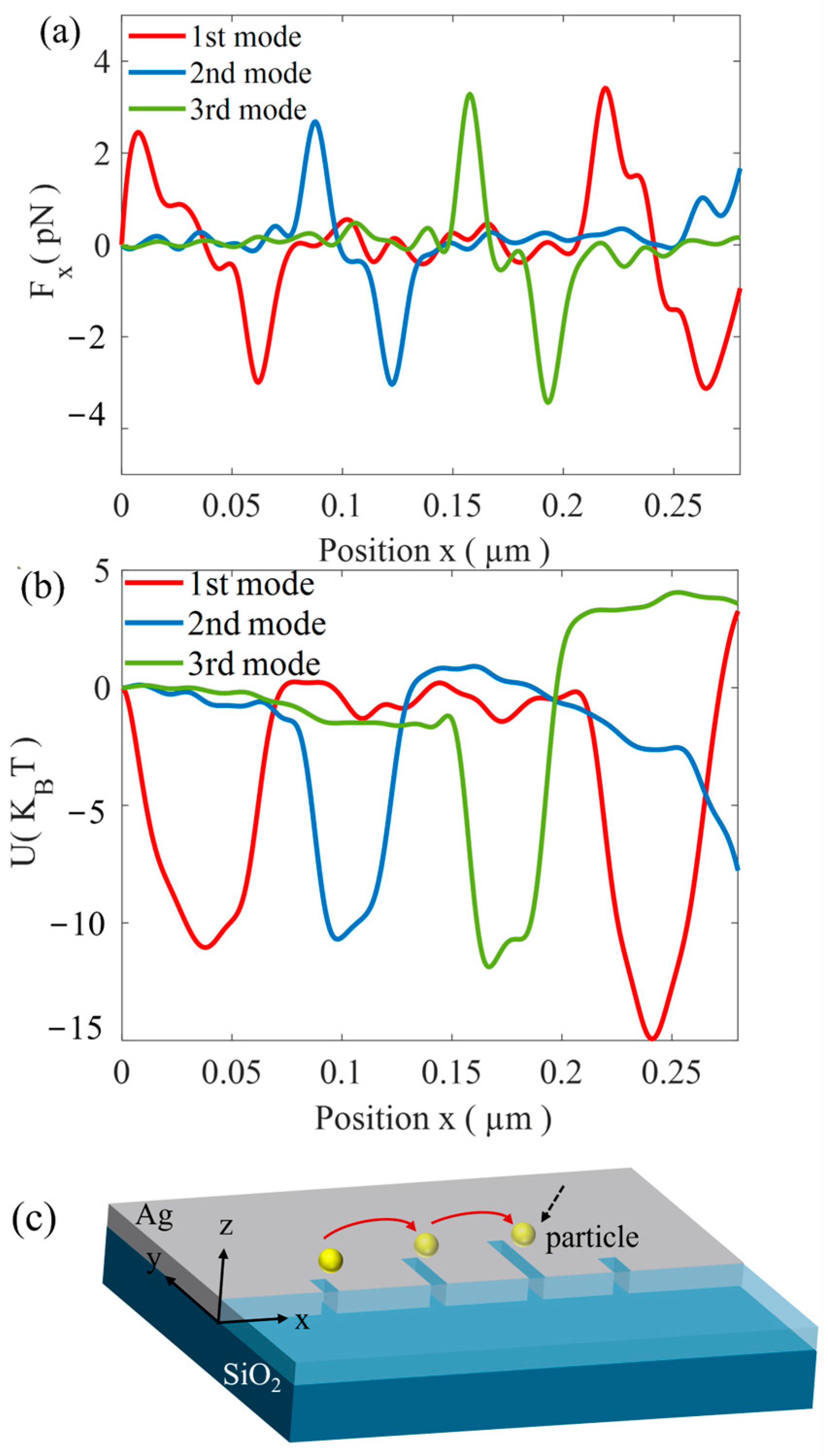
Figure 5.
The trapping properties in the x direction for the third-order mode at the incident level of 10 mW. (a) Optical force Fx versus the central position x of the object. (b) Potential well in the x direction. It can be observed that the object tends to be trapped at the longest slot.
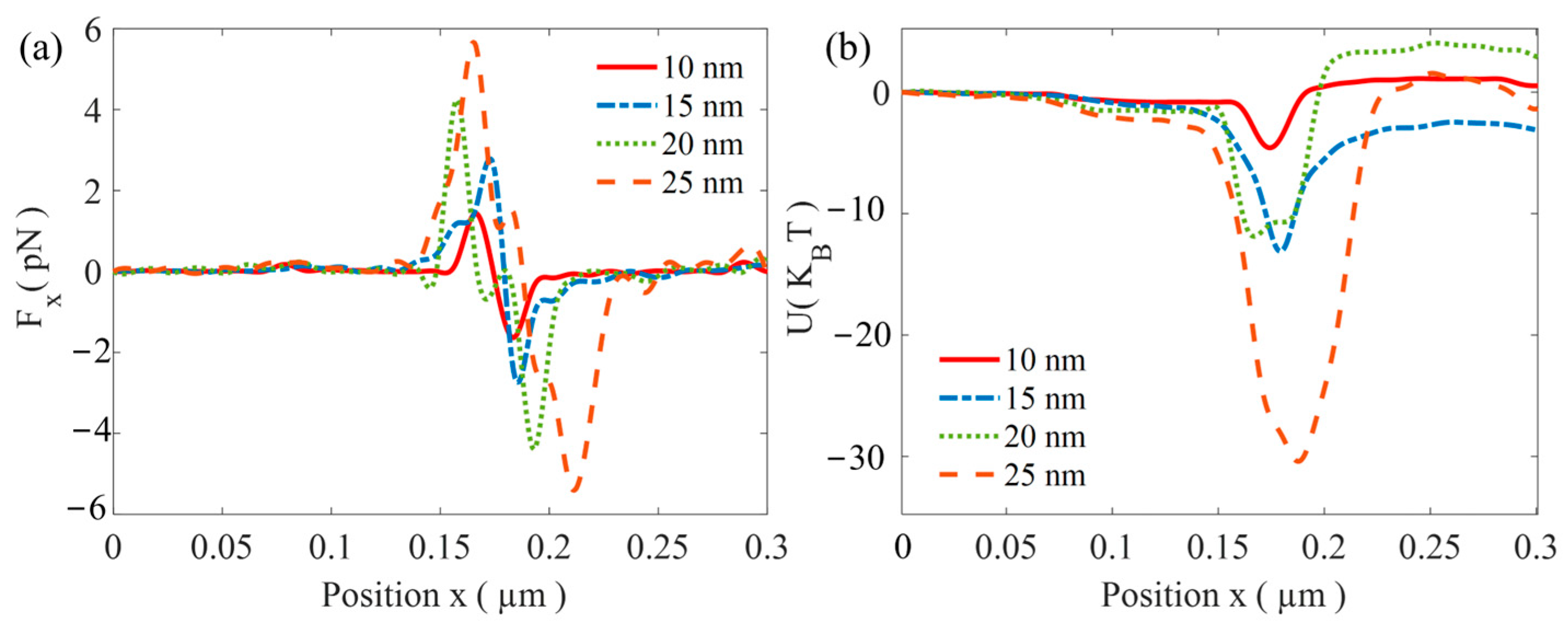
Figure 6.
Trapping properties for the third mode are presented separately for the y (left) and z (right) directions. For the y direction, the electric field profile |(E)| is shown in (a), followed by the optical force Fy in (b) and the corresponding potential well in (c). Similarly, for the z direction (d), the electric field profile |(E)|. (e) The exerted optical force Fz and (f) the resulting potential well.
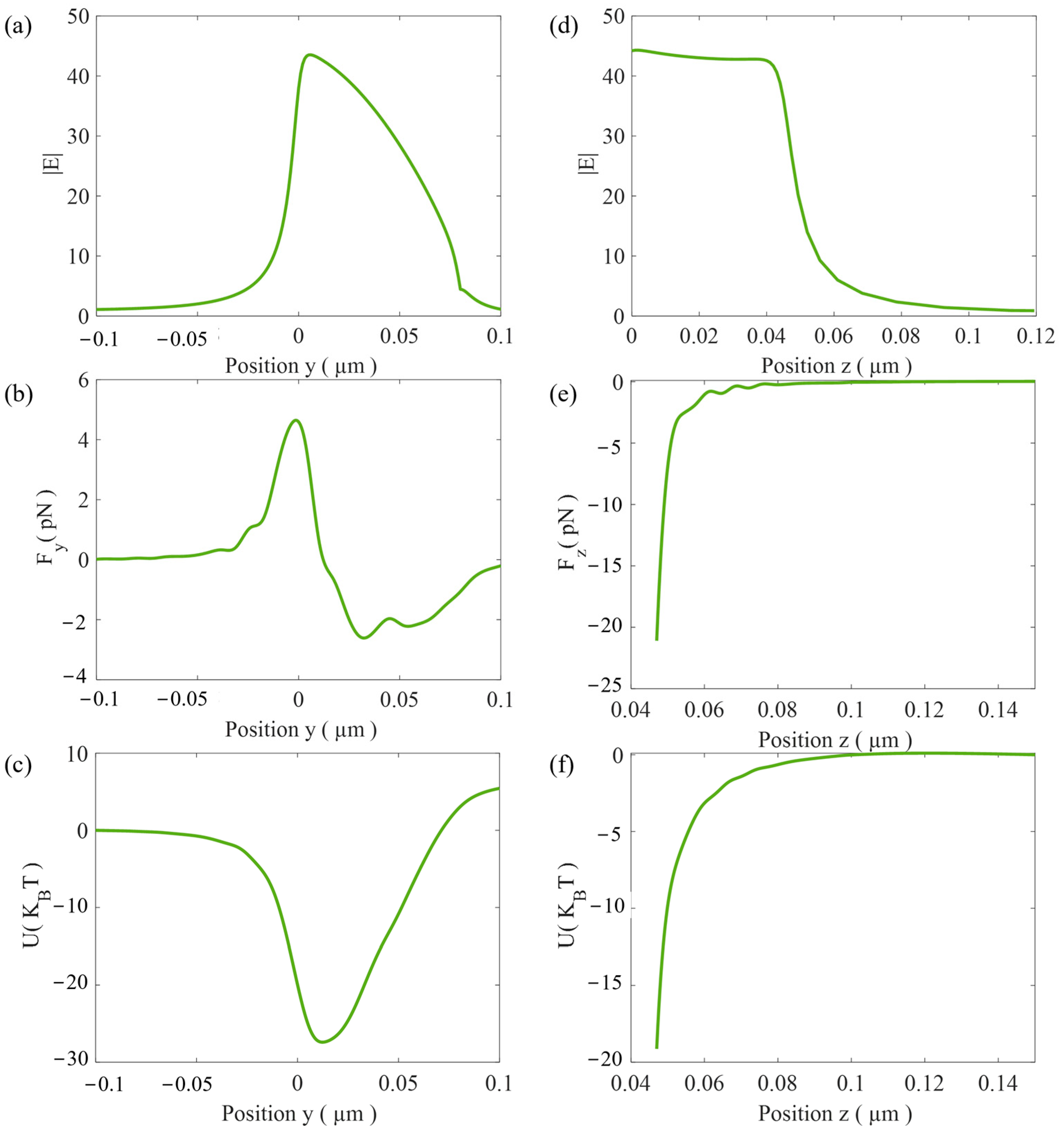
Figure 5 presents the optical forces and potential wells along the x direction for gold spheres with radii r = 10 nm, 15 nm, 20 nm, and 25 nm. Figure 5a shows the optical forces. The results indicate that the maximum optical forces Fx for the four different nanoparticles are approximately 1.4 pN, 2.8 pN, 4.4 pN, and 5.7 pN, respectively. In all cases, the particles are trapped near x = 175 nm, at the longest slot. Since the optical force increases linearly with the incident power, a potential well depth greater than 10 kBT is required for stable trapping. For the third mode, the minimum incident powers required for stable trapping of gold nanoparticles with radii of 10 nm, 15 nm, 20 nm, and 25 nm are about 22, 10, 8.3, and 3.3 mW, respectively. Therefore, at an incident power of 10 mW, the smallest stably trapped gold nanoparticle has a radius of 15 nm.
3.2. The Optical Trapping in the y-z Plane
As demonstrated in the previous section, the stable trapping at different positions along the x-axis can be achieved through switching between the resonant modes. And the trapping stability in the y-axis and z-axis still requires further theoretical calculation. Here, we calculate the optical forces and potential trap along these axes, and the results are shown in Figure 6.
To fully characterize the trapping stability, we analyzed the trapping properties in the transverse y and vertical z directions for the third-order mode (for the first mode and the second-order mode, similar results are obtained, and they are not repeated here). Figure 6a reveals that the intensity maximum is located at the edge of the silver layer. Based on a large intensity gradient, the corresponding optical force Fy and potential well (28 kBT) are large enough that the gold nanoparticle can be stably trapped at y = 10 nm, which is near the edge of the silver layer. The results are shown in Figure 6b,c. In the z direction, the optical force consistently pulls the nanoparticle toward the surface; the particle with a radius of 20 nm could be trapped within the potential of 20 kBT (see Figure 6d–f).
In the x direction, the trapping position is wavelength-selective, and more importantly, the separation between two trapped particles can be precisely tuned. The analysis above demonstrates that stable trapping is achieved along the y and z directions. Under the first mode, the two objects are trapped at the shortest slots near the center of the nanostructure. When the second mode is activated, the particles are released first and subsequently jump to the nearest medium-length slots on both sides, resulting in a larger spacing. Further switching to the third mode, the particles eventually move to the longest slots on both sides, and their separation increases accordingly. Repeating the above procedure periodically, the distance between the trapped particles gradually increases, while reversing the above process, the distance gradually decreases.
3.3. The Inter-Distance Tuning Between Two Trapped Nanoparticles
In this section, in order to illustrate the method of inter-distance tuning, we modeled the particle motion by a generalized Langevin equation to model particle motion [39]
where the optical force F(x(t), t) is a position- and time-dependent force acting on the particle (using the Maxwell stress tensor (MST) integration method). x(t) is the particle’s position along the x-axis. η is the fluid viscosity, β is the viscous drag coefficient (corrected for surface effect when the particle is near the substrate [40], and W(t) represents a Gaussian random white noise, which satisfies ⟨W(t)⟩ = 0 and ⟨W(t)2⟩ = 1. Our numerical simulation uses a discrete random sequence Wi to approximate the continuous process W(t). The values are designed to have a zero mean and a variance of 1/Δt. The equation of motion is solved using the stochastic Euler’s method
where Δt is the time interval. The optical traps are based on a dynamic equation. Near the hot spots, thermal noise tries to push particles out of the trap, and optical gradient force pulls particles back to the center of the trap well. And the gold nanoparticles are immersed in water, with an initial velocity (from the kinetic energy formula)
During the distance tuning process, the optical force F(x(t), t) varies spatially with the excitation of different resonant modes. The transporting mechanism is as follows:
From t = 0 to t1, the first-order mode is activated. Both particles are released from the center. The optical force of the first mode exhibits potential wells located at the shortest slots. The particles are driven by the optical force, viscous resistance, and Brownian force; as a result, particles are trapped at the nearest short slot within a few milliseconds.
From t1 to t2, the first mode is deactivated while the second mode is activated. The potential wells accordingly shift to the medium-length slots. Driven by the new space- and time-dependent optical force F(x(t), t), the particles move to the new equilibrium positions (medium slots) within a few milliseconds.
In the subsequent illumination cycle, the third mode is activated, and the particles shift again according to the longest slot. By periodically repeating the sequence in the order first mode→ second mode→ third mode, the particles can be transported stepwise along the x direction.
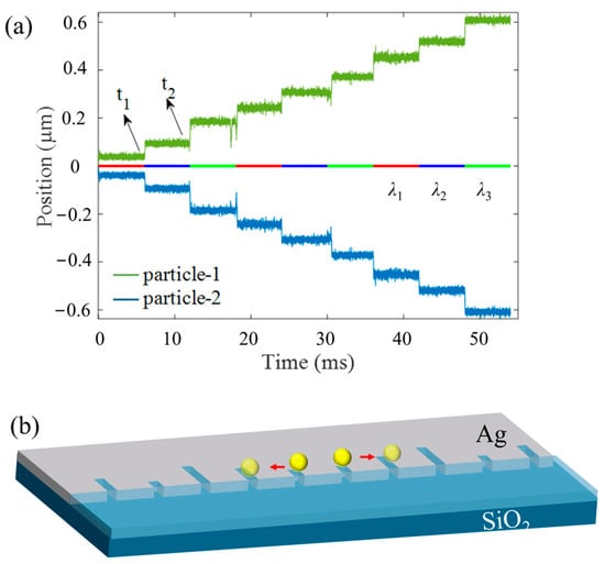
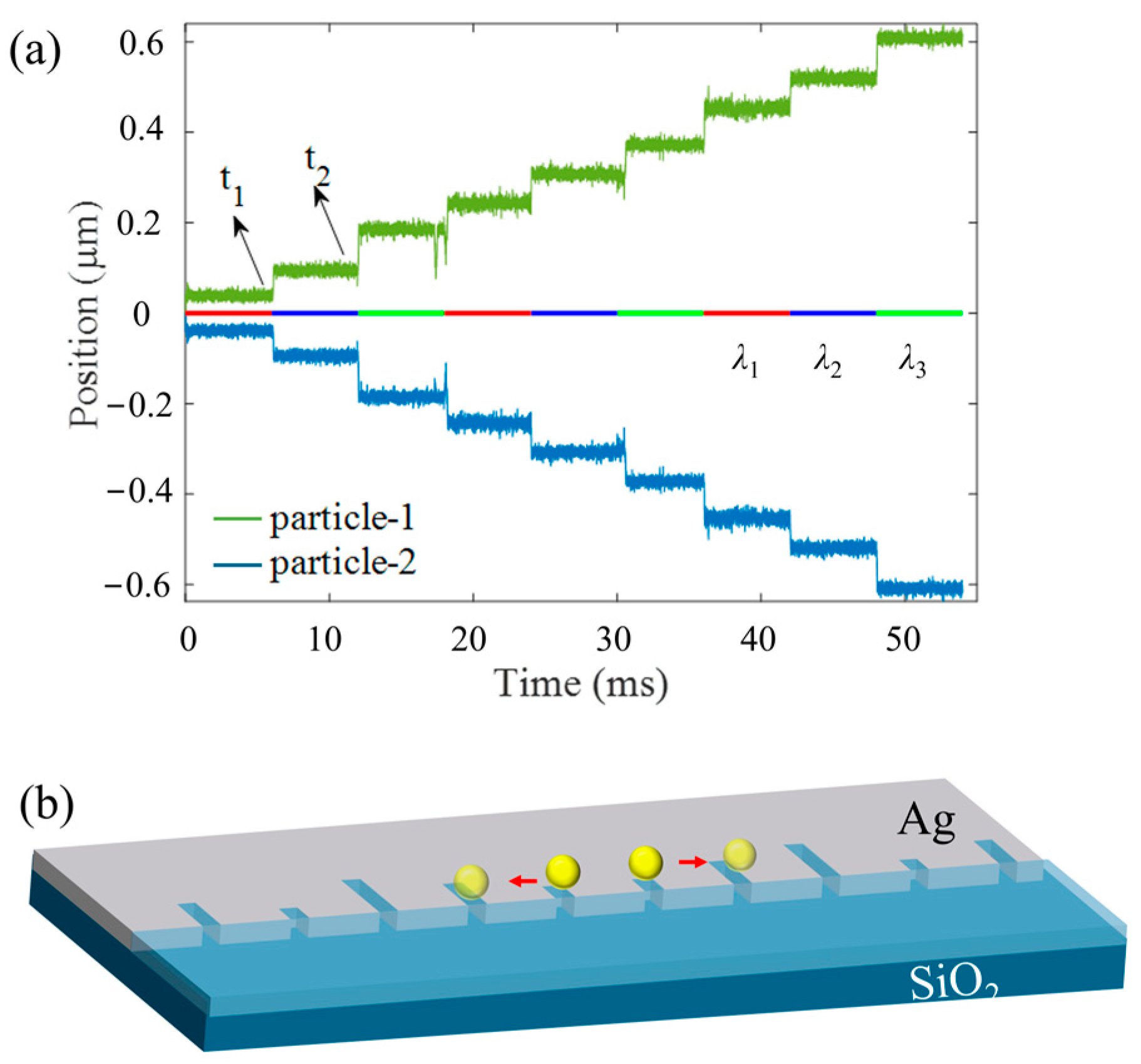
As shown in Figure 7, we demonstrate that the separation between two particles can be tuned precisely through tuning the excitation wavelength. The displacement of the two gold particles was calculated, and the results show that their spacing increases in a stepwise manner over time. Specifically, when the first resonant mode (λ1 = 960 nm) is switched on, both particles are trapped at the shortest slots (x = ±0.035 μm), corresponding to an inter-distance of 70 nm. Subsequently, the second mode is activated (the first mode is switched off simultaneously), the wavelength is switched to λ2 = 1046 nm, and the particles are first released from the shortest slots and then jump to the nearest medium-length slot. Accordingly, the distance between the two particles increases to 210 nm. Further switching the excitation wavelength to λ3 = 1460 nm causes particles to eventually move to the longest slots, resulting in an inter-distance of 350 nm. Figure 6b shows a representative trajectory of a particle as it moves along the structure. By periodically repeating the sequence in the order λ1 → λ2 → λ3, the distance between particles gradually increases. Conversely, when the sequence is reversed (λ3 → λ2 → λ1), the distance gradually decreases.
Figure 7.
(a) Simulated trajectories of two gold particles with a mode switching time of 6.6 ms. Perturbations in the curves arise from the Brownian motion of the particles. The inset line indicates the turn-on time of each mode, with t1 and t2 marking the mode-switching events. (b) Representative trajectories of the two gold particles as they move away from the center. The two particles move in opposite directions.
Furthermore, the nano-optical conveyor belt enables simultaneous trapping of multiple particles on the surface, ensuring the effectiveness of the multiparticle trapping process. During this process, each light pulse lasts for 6.6 ms before switching to the next mode, and the entire pattern repeats at a frequency of 50 Hz. The incident intensity of each beam is 10 mW, ensuring that the trapping wells are deeper than 10 kBT. The two gold particles are released at time t = 0 s from the point x = 0 nm and are tracked for t = 60 ms. In our simulations, the trajectories of two particles are calculated. Due to the random Brownian motion, the simulated paths differ, but the step size of particles remains the same.
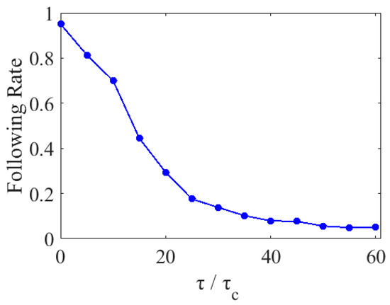
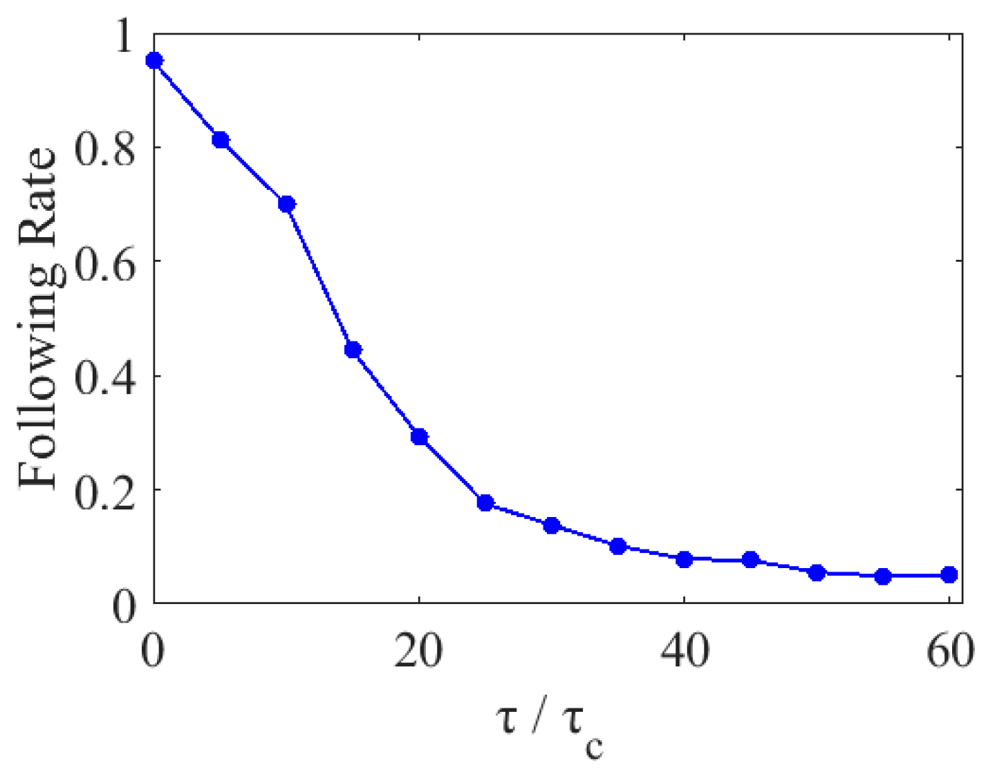
In order to investigate the impact of excitation switching speed on transport efficiency, we analyzed the successful following rates over three complete periods. We defined the following rate as the proportion of particles that, starting from the origin, successfully reached the longest slot after three periods, each period consisting of three wavelength switching steps. In Figure 8, the response time τ represents the wavelength switching interval, which corresponds to the time span between incident mode switching events. As shown in Figure 8, through simulations involving 1000 particles, we observed that as the response time increased (i.e., as the switching interval speed decreased), the following rate exhibited a downward trend. This decline is attributed to the enhanced influence of thermal motion. The variation follows an exponential decay law characterized by a time constant τc; the relationship between τc and the viscous drag coefficient is given by τc = β/k [40], where k is the effective trap stiffness.
Figure 8.
Analysis of the influence of excitation switching response time τ on the following rate across three periods. Here, the response time τ represents the time interval required for one mode-switching operation. And the time constant τc = β/k, where β is the viscous drag coefficient, and k is the effective trap stiffness.
4. Discussion
In summary, we have designed a mirror-symmetric optical conveyor belt that allows for bidirectional manipulation of nanoparticles. The structure is designed to operate at three resonant wavelengths. Numerical simulations confirm that the optical forces are sensitive to wavelength, and each resonant mode offers sufficient trapping stiffness and a deep potential well. By tuning the wavelength, the individual particle can be directionally transported along a 1D trajectory with a step size of 70 nm. Furthermore, the inter-distance between two trapped particles can be precisely controlled by switching the repeating sequence of resonant wavelengths. This mechanism allows two trapped particles to move toward or away from each other in a programmable manner. This method holds huge potential for nanoparticle assembly, biomedicine, light-driven micro-robotics, and drug delivery.
Author Contributions
Conceptualization, L.W.; formal analysis and numerical simulation, L.W. and B.S.; data analysis, L.W. and Y.S.; original draft preparation, L.W. and B.S.; funding acquisition, L.W. All authors have read and agreed to the published version of the manuscript.
Funding
This work was supported by the Natural Science Foundation of the Jiangsu Higher Education Institutions of China (Grant No. 23JKB140010).
Data Availability Statement
Relevant data are available from the authors upon reasonable request.
Acknowledgments
The authors gratefully acknowledge the support from Nanjing Tech University.
Conflicts of Interest
The authors declare no conflicts of interest.
References
- Ashkin, A. Acceleration and trapping of particles by radiation pressure. Phys. Rev. Lett. 1970, 24, 156. [Google Scholar] [CrossRef] [Scilit]
- Palagi, S.; Mark, A.G.; Reigh, S.Y.; Melde, K.; Qiu, T.; Zeng, H.; Parmeggiani, C.; Martella, D.; Sanchez-Castillo, A.; Kapernaum, N.; et al. Structured light enables biomimetic swimming and versatile locomotion of photoresponsive soft microrobots. Nat. Mater. 2016, 15, 647–653. [Google Scholar] [CrossRef] [Scilit]
- Niffenegger, R.J.; Stuart, J.; Sorace-Agaskar, C.; Kharas, D.; Bramhavar, S.; Bruzewicz, C.D.; Loh, W.; Maxson, R.T.; Mcconnell, R.; Reens, D.; et al. Integrated multi-wavelength control of an ion qubit. Nature 2020, 586, 538–542. [Google Scholar] [CrossRef] [Scilit]
- Wiederhecker, G.S.; Chen, L.; Gondarenko, A.; Lipson, M. Controlling photonic structures using optical forces. Nature 2009, 462, 633–636. [Google Scholar] [CrossRef] [Scilit] [PubMed]
- Zhao, Y.; Saleh, A.A.E.; van de Haar, M.A.; Baum, B.; Briggs, J.A.; Lay, A.; Reyes-Becerra, O.A.; Dionne, J.A. Nanoscopic control and quantification of enantioselective optical forces. Nat. Nanotechnol. 2017, 12, 1055–1059. [Google Scholar] [CrossRef] [Scilit]
- Ashkin, A.; Dziedzic, J.M. Optical trapping and manipulation of viruses and bacteria. Science 1987, 235, 1517–1520. [Google Scholar] [CrossRef] [Scilit] [PubMed]
- Righini, M.; Ghenuche, P.; Cherukulappurath, S.; Myroshnychenko, V.; de Abajo, F.J.G.; Quidant, R. Nano-optical trapping of Rayleigh particles and Escherichia coli bacteria with resonant optical antennas. Nano Lett. 2009, 9, 3387–3391. [Google Scholar] [CrossRef] [Scilit] [PubMed]
- Soltani, M.; Lin, J.; Forties, R.A.; Inman, J.T.; Saraf, S.N.; Fulbright, R.M.; Lipson, M.; Wang, M.D. Nanophotonic trapping for precise manipulation of biomolecular arrays. Nat. Nanotechnol. 2014, 9, 448–452. [Google Scholar] [CrossRef] [Scilit]
- Wu, D.; Lou, Y.; Ma, J.; Min, Q.; Wang, Y.; Pang, Y. Unidirectional Emission from a Single Upconversion Nanoparticle Optically Trapped in a Plasmonic Nanoantenna. ACS Photonics 2025, 12, 6318–6324. [Google Scholar] [CrossRef] [Scilit]
- Ma, J.; Zhang, H.; Lou, Y.; Min, Q.; Wu, D.; Wang, Y.; Pang, Y. Deterministic Assembly of Single-Emitter Plasmonic Antenna for Ultrahigh Photoluminescence Enhancement. Nano Lett. 2024, 24, 12605–12611. [Google Scholar] [CrossRef] [Scilit]
- Juan, M.L.; Gordon, R.; Pang, Y.; Eftekhari, F.; Quidant, R. Self-induced back-action optical trapping of dielectric nanoparticles. Nat. Phys. 2009, 5, 915–919. [Google Scholar] [CrossRef] [Scilit]
- Crozier, K.B. Plasmonic nanotweezers: What’s next? ACS Photonics 2024, 11, 321–333. [Google Scholar] [CrossRef] [Scilit]
- Escobedo, C.; Brolo, A.G. Synergizing microfluidics and plasmonics: Advances, applications, and future directions. Lab A Chip 2025, 25, 1256–1281. [Google Scholar] [CrossRef] [Scilit] [PubMed]
- Hu, Y.; Chen, Z.; Yi, Z.; Cheng, S.; Ahmad, S.; Li, B. Ultra wideband solar energy absorption device based on multi-layered Ti-InAs cylinder metasurface. Phys. E Low Dimens. Syst. Nanostruct. 2026, 180, 116514. [Google Scholar] [CrossRef] [Scilit]
- Ai, Z.; Liu, H.; Cheng, S.; Zhang, H.; Yi, Z.; Zeng, Q.; Wu, P.; Zhang, J.; Tang, C.; Hao, Z. Four peak and high angle tilted insensitive surface plasmon resonance graphene absorber based on circular etching square window. J. Phys. D Appl. Phys. 2025, 58, 185305. [Google Scholar] [CrossRef] [Scilit]
- Liu, G.; Wang, Z.; Sun, W.; Lin, X.; Wang, R.; Li, C.; Zong, L.; Fu, Z.; Liu, H.; Xu, S. Robust emission in near-infrared II of lanthanide nanoprobes conjugated with Au (LNPs-Au) for temperature sensing and controlled photothermal therapy. Chem. Eng. J. 2023, 452, 139504. [Google Scholar] [CrossRef] [Scilit]
- Li, Y.; Liu, W.; Liu, R.; Gao, J.; Feng, J.; Xu, S.; Li, Z.; Jiang, S.; Du, X. 3D hybrid arrayed Ag/MOF multi-plasmon resonant cavity system for high-performance SPR sensing. Opt. Laser Technol. 2023, 167, 109825. [Google Scholar] [CrossRef] [Scilit]
- Shi, Y.; Song, Q.; Toftul, I.; Zhu, T.; Yu, Y.; Zhu, W.; Tsai, D.P.; Kivshar, Y.; Liu, A.Q. Optical manipulation with metamaterial structures. Appl. Phys. Rev. 2022, 9, 031303. [Google Scholar] [CrossRef] [Scilit]
- Lu, C.; Wang, B.; Fang, X.; Tsai, D.P.; Zhu, W.; Song, Q.; Deng, X.; He, T.; Gong, X.; Luo, H.; et al. Nanoparticle deep-subwavelength dynamics empowered by optical meron–antimeron topology. Nano Lett. 2023, 24, 104. [Google Scholar] [CrossRef] [Scilit]
- Zhang, Y.; Min, C.; Dou, X.; Wang, X.; Urbach, H.P.; Somekh, M.G.; Yuan, X. Plasmonic tweezers: For nanoscale optical trapping and beyond. Light Sci. Appl. 2021, 10, 59. [Google Scholar] [CrossRef] [Scilit]
- Zhang, S.; Xu, B.; Elsayed, M.; Nan, F.; Liang, W.F.; Valley, J.K.; Liu, L.Q.; Huang, Q.; Wu, M.C.; Wheeler, A.R. Optoelectronic tweezers: A versatile toolbox for nano-/micro-manipulation. Chem. Soc. Rev. 2022, 51, 9203. [Google Scholar] [CrossRef] [Scilit] [PubMed]
- Spitzberg, J.D.; Zrehen, A.; van Kooten, X.F.; Meller, A. Plasmonic-nanopore biosensors for superior single-molecule detection. Adv. Mater. 2019, 31, 1900422. [Google Scholar] [CrossRef] [Scilit]
- Garoli, D.; Yamazaki, H.; Maccaferri, N.; Wanunu, M. Plasmonic nanopores for single-molecule detection and manipulation: Toward sequencing applications. Nano Lett. 2019, 19, 7553–7562. [Google Scholar] [CrossRef] [Scilit]
- Anyika, T.; Hong, I.; Ndukaife, J.C. Mirror-enhanced plasmonic nanoaperture for ultrahigh optical force generation with minimal heat generation. Nano Lett. 2023, 23, 11416–11423. [Google Scholar] [CrossRef] [Scilit] [PubMed]
- Asadzadeh, H.; Renkes, S.; Kim, M.; Alexandrakis, G. Multi-physics simulations and experimental comparisons for the optical and electrical forces acting on a silica nanoparticle trapped by a double-nanohole plasmonic nanopore sensor. Sens. Bio-Sens. Res. 2023, 41, 100581. [Google Scholar] [CrossRef] [Scilit] [PubMed]
- Hong, C.; Yang, S.; Ndukaife, J.C. Optofluidic control using plasmonic TiN bowtie nanoantenna. Opt. Mater. Express 2019, 9, 953–964. [Google Scholar] [CrossRef] [Scilit]
- Li, Z.S.; Lu, T.W.; Huang, P.R.; Lee, P.T. Efficient nano-tweezers via a silver plasmonic bowtie notch with curved grooves. Photonics Res. 2021, 9, 281–288. [Google Scholar] [CrossRef] [Scilit]
- Zaman, M.Z.; Hesselink, L. Dynamically controllable plasmonic tweezers using C-shaped nano-engravings. Appl. Phys. Lett. 2022, 121, 181108. [Google Scholar] [CrossRef] [Scilit]
- Wang, Y.; Wei, S.; Ju, Z.; Min, C.; Somekh, M.; Yuan, X. Dynamic optical tweezers for metallic particle manipulation via tunable plasmonic fields. Photonics Res. 2024, 12, 1840–1845. [Google Scholar] [CrossRef] [Scilit]
- Qin, J.; Wu, X.; Krueger, A.; Hecht, B. Light-driven plasmonic microrobot for nanoparticle manipulation. Nat. Commun. 2025, 16, 2570. [Google Scholar] [CrossRef] [Scilit]
- Verschueren, D.V.; Pud, S.; Shi, X.; De Angelis, L.; Kuipers, L.; Dekker, C. Label-free optical detection of DNA translocations through plasmonic nanopores. ACS Nano 2018, 13, 61–70. [Google Scholar] [CrossRef] [Scilit] [PubMed]
- Ma, X.; Sim, S.J. Single plasmonic nanostructures for biomedical diagnosis. J. Mater. Chem. B 2020, 8, 6197−6216. [Google Scholar] [CrossRef] [Scilit] [PubMed]
- Li, Z.; Leustean, L.; Inci, F.; Zheng, M.; Demirci, U.; Wang, S. Plasmonic-based platforms for diagnosis of infectious diseases at the point-of-care. Biotechnol. Adv. 2019, 37, 107440. [Google Scholar] [CrossRef] [Scilit] [PubMed]
- Ren, Y.; Chen, Q.; He, M.; Zhang, X.; Qi, H.; Yan, Y. Plasmonic optical tweezers for particle manipulation: Principles, methods, and applications. ACS Nano 2021, 15, 6105. [Google Scholar] [CrossRef] [Scilit]
- Xu, F.; Wang, L.; Mu, R.; Zheng, F.; Jiang, M.; Wang, G. Levitated 2D manipulation on dielectric metasurface by the tuning of polarization states. Opt. Lett. 2024, 49, 530. [Google Scholar] [CrossRef] [Scilit] [PubMed]
- Ye, F.; Inman, J.T.; Hong, Y.; Hall, P.M.; Wang, M.D. Resonator nanophotonic standing-wave array trap for single-molecule manipulation and measurement. Nat. Commun. 2022, 13, 77. [Google Scholar] [CrossRef] [Scilit] [PubMed]
- Sneh, T.; Corsetti, S.; Notaros, M.; Kikkeri, K.; Voldman, J.; Notaros, J. Optical tweezing of microparticles and cells using silicon-photonics-based optical phased arrays. Nat. Commun. 2024, 15, 8493. [Google Scholar] [CrossRef] [Scilit]
- McPeak, K.M.; Jayanti, S.V.; Kress, S.J.; Meyer, S.; Iotti, S.; Rossinelli, A.; Norris, D.J. Plasmonic films can easily be better: Rules and recipes. ACS Photonics 2015, 2, 326–333. [Google Scholar] [CrossRef] [Scilit]
- Volpe, G.; Volpe, G. Simulation of a Brownian particle in an optical trap. Am. J. Phys. 2013, 81, 224–230. [Google Scholar] [CrossRef] [Scilit]
- Svoboda, K.; Block, S.M. Biological applications of optical forces. Annu. Rev. Biophys. Biomol. Struct. 1994, 23, 247–285. [Google Scholar] [CrossRef]
Disclaimer/Publisher’s Note: The statements, opinions and data contained in all publications are solely those of the individual author(s) and contributor(s) and not of MDPI and/or the editor(s). MDPI and/or the editor(s) disclaim responsibility for any injury to people or property resulting from any ideas, methods, instructions or products referred to in the content. |
© 2026 by the authors. Licensee MDPI, Basel, Switzerland. This article is an open access article distributed under the terms and conditions of the Creative Commons Attribution (CC BY) license.