


Abstract
With the development of a photoelectric system in the aviation field, the requirements for airborne equipment have increased accordingly. The photoelectric aiming and tracking turntable as a crucial component in the photoelectric system has stringent requirements on weight and volume. A new type of structure with the coaxial dual-axis turntable has been researched, it adopts a structural form with two rotating axes connected in series and rotating Risley gratings by two independent mechanical shaft axes to complete pointing, capturing and tracking functions. This type of structure features compactness, small moments of inertia and fast response speed; this miniaturized aiming and tracking system with Risley grating is more suitable for airborne equipment. The Risley grating aiming and tracking system adjusts the optical axis angle using two rotating Risley gratings; it realizes beam pointing within a conical range through polarization diffraction. The aiming and tracking system based on Risley grating has small moving parts so it is lighter; it has more advantages than the traditional turntable. Although the tracking range is relatively limited, it still offers significant lightweight effects for certain special applications and can effectively reduce weight and volume. In this paper, we research the system of aiming and tracking with Risley gratings, the influence of mechanical turntable parameters on the system’s tracking accuracy is analyzed based on its working principle; error analysis and allocation of turntable errors are carried out. Subsequently, the decoupling model of the system is analyzed and system errors are compensated; the miniaturized tracking and calibration system based on Risley gratings is developed. Then, the photoelectric testing method based on dual reference mirrors proposed by us is used to test the coaxiality and axis jitter accuracy of the turntable. The system has an effective aperture > Φ120 mm, weight < 10 kg and volume < Φ190 × 155 mm. Pointing accuracy and dynamic tracking test show that the system’s pointing accuracy is ≯10″ and tracking accuracy is ≯380 μrad. Finally, a field tracking test is carried out and verify the system’s capability and performance.
1. Introduction
With the advancement of technology, the aiming and tracking technology for moving platforms has been constantly improving, and the electro-optical pod system has achieved rapid development. Due to the mature technology, simple structure and high reliability, the mechanical servo aiming and tracking turntable has always been the preferred structure for electro-optical pods. The mechanical servo turntable is generally a two-dimensional adjustment system, which realizes the adjustment of the optical axis angle and completes the aiming and tracking of moving targets. Traditional servo turntable types have gimbals, circumferential scanning and a single pendulum mirror; each has its own characteristics. The gimbal structure features mature technology, simple for control and large motion range, but it has a large volume and weight. The circumferential scanning type offers advantages such as a large range and few moving parts, yet it has a large rotating envelope during operation and suffers from image rotation issues. The single pendulum mirror type is small in size, light in weight and has few moving parts, but its working range is subject to certain limitations. In recent years, coaxial servo turntables have gradually emerged; a typical representative is the rotating double-prism turntable which consists of two coaxially rotating optical prisms. It achieves two-dimensional angle adjustment of the optical axis through the coordinated rotation of the two prism bases on the optical axis deflection principle. The rotating double-prism turntable has advantages including small size, light weight, insensitivity to vibration and low power consumption, enabling high-precision optical axis tracking of the system in certain specific occasions.
A series of studies on coaxial aiming and tracking turntables have been conducted both domestically and internationally. NASA has carried out a series of studies on rotating double-prism coaxial turntables. In 2003, NASA developed the Boresight Adjustment Mechanism (BAM) for the Geoscience Laser Altimeter System (GLAS). This mechanism uses two prisms to accurately guide the incident laser, and it achieves a pointing accuracy of less than 1″ within the range of ±300″ [1]. Ball Corporation designed a rotating triple-prism structure for coaxial turntables; compared with the rotating double-prism structure, it adds an additional series-connected prism group, which is used to eliminate the nonlinearity problem existing in rotating double prisms, and that improves the dynamic performance to a certain extent. This structure has a pointing range of up to 120° and can achieve smooth tracking at 10/s [2,3]. Lockheed Martin developed a micro rotating double-prism pointing mechanism for spacecraft with a clear aperture of 19 mm, prism wedge angle of 0.75°, maximum rotational speed of 6 rpm, beam deflection accuracy of 25 μrad, diameter of 58 mm, and length of 64 mm [4]. Defence Research and Development Canada developed an imaging system based on rotating double prisms. This system is used for area scanning as well as target search and tracking and supports step-stare imaging. To achieve large-field-of-view and high-resolution imaging, the motor is connected to the prisms via a timing belt with a gear ratio of 4:1 [5]. The research institutions on coaxial turntables in China include the Shanghai Institute of Optics and Fine Mechanics (SIOM), the Changchun Institute of Optics, Fine Mechanics and Physics (CIOMP), the National University of Defense Technology (NUDT), and Tongji University. In 2021, SIOM designed a transceiving coaxial laser communication payload based on double prisms to meet the communication requirements of low-orbit small satellite constellations. This payload features small size, light weight and a large field of view; it has undergone in-orbit testing and verification on the XY-2 satellite. Its acquisition success rate reached 100%, and the root mean square (RMS) value of tracking accuracy after link establishment was less than 30 μrad [6]. Livox company under DJI has developed a variety of coaxial double-prism rotating mechanisms for laser scanning. The transceiving module emits laser light and then adjusts the optical path by rotating the prisms in the two scanning modules, allowing the laser to be emitted at a specific angle and return along the original path to complete laser scanning [7]. In 2010, NUDT developed a rotating double-prism prototype with an aperture of 70 mm and a beam deflection angle of 10°. It has two working modes of beam scanning and step imaging; the relevant experiments were conducted for each mode, respectively [8]. In 2023, CIOMP conducted research on the pointing accuracy of rotating double prisms applied in laser communication. The driving method adopts a stepping motor combined with gears, and high-precision absolute grating encoders are used to achieve precise control of the rotation angle [9].
The researchs on coaxial aiming and tracking turntable leading to the following three conclusions. The coaxial turntable features low mass and a compact structure, has better development prospects in airborne tracking and pointing systems. The coaxial turntable is typically represented by the rotating double-prism configuration. Nevertheless, due to the optical characteristics of prisms, it is not suitable for large-aperture and large-angle beam deflection systems and is thus commonly used in laser communication.
The double-prism aiming and tracking turntables still have a problem with large volume and heavy mass, it is unsuitable for small airborne platforms, so in this paper we investigates a coaxial turntable integrated with Risley gratings. The proposed turntable is characterized by lower mass and smaller volume, it achieves larger aperture and deflection angles compared with rotating double-prism turntables. In summary, the rotating double-grating turntable is worthy of further research. Furthermore, it has strong environmental adaptability, and its rotating components are symmetrical along the axis which results in smaller volume and lighter weight. It is applicable to tracking applications including laser communication and airborne optical axis tracking. Compared with double-prism turntables, it has greater advantages in terms of weight and miniaturization.
2. Materials and Methods
2.1. Control Model of Double-Risley Grating Turntable for Aiming and Tracking
Since the Risley grating is a polarization system and cannot image natural targets, an illumination system is additionally designed in the actual system to realize laser illumination of the tracking target. The Risley grating turntable captures and tracks the polarized light reflected by the target. In the system, the Risley grating turntable is the primary tracking system for pointing and aiming the target in the initial acquisition stage. After capturing the target, it performs coarse tracking, providing stable target assurance for the fine tracking unit and ensuring the operation of fine tracking.
2.1.1. Principle of Double-Grating Angle Adjustment
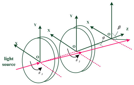
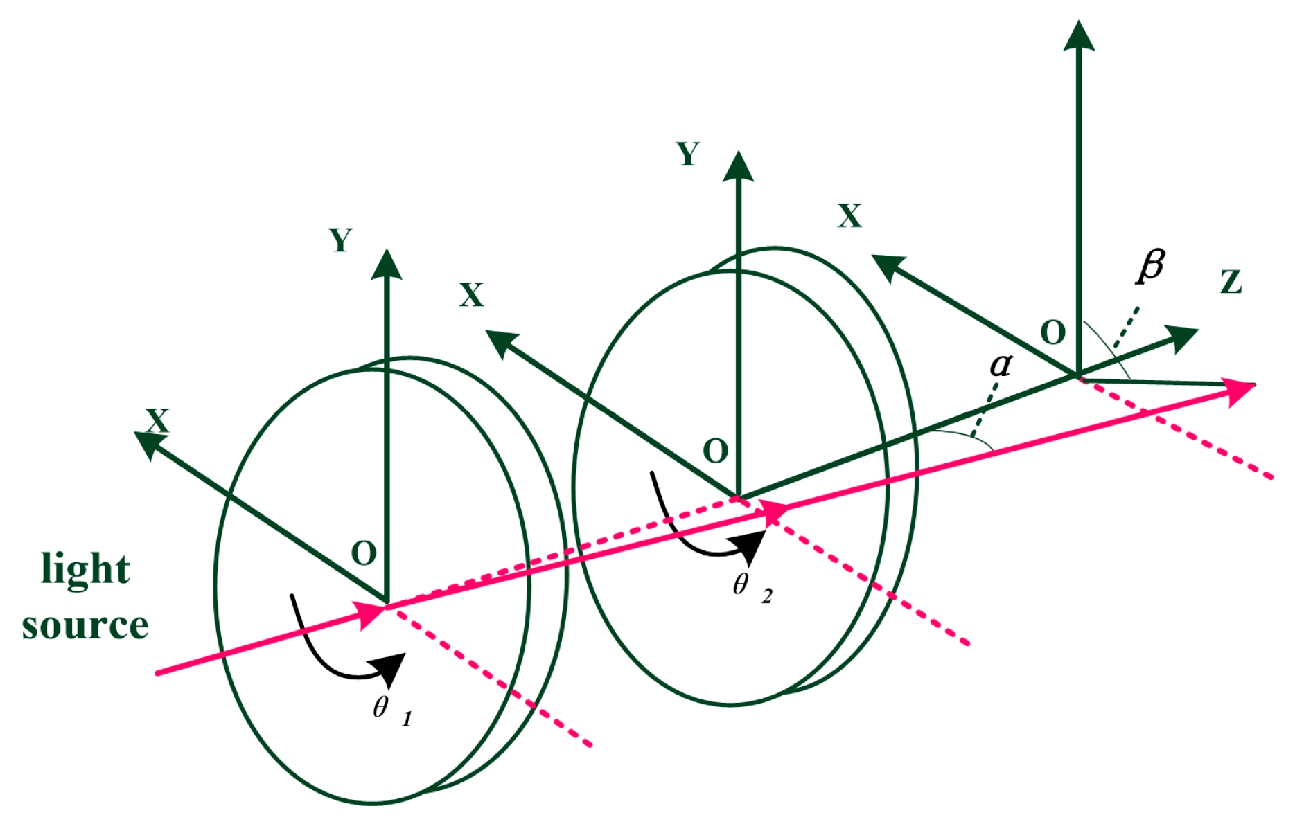
Risley gratings generate a diffraction effect through surface gratings, deflecting the angle of transmitted light to achieve the same effect as prisms; but the grating features a planar structure without wedge-shaped components, resulting in a more compact size. In addition, it has no eccentricity issue that makes it more advantageous for servo systems The turntable structure can be processed into a circular thin-sheet form, featuring small volume, light weight and the mass distribution is symmetrical. The aiming and tracking system employs Risley gratings; two-dimensional adjustment of the light beam angle is achieved through rotation driven by a servo system. Based on the principle of Risley gratings and the grating diffraction equation, a double-grating diffraction model is established as shown in Figure 1. Source light exits from the left side and deflects in the two-dimensional x and y directions after passing through the two gratings during aiming, the red line represents the emitted light, θ1 and θ2 are the rotation angles of the gratings, α and β are the azimuth and elevation angle of the light. By combining the rotation angles of the two gratings, the angle of the source light can be adjusted to achieve target aiming. During target tracking, the angle information of the target’s optical axis obtained by the tracking camera is used to inversely calculate the required rotation angles of the gratings. In the paper, the grating period is 8.22 μm and the operating wavelength is 1064 nm, so the deflection angle of a single grating is 7.5° and that of two gratings is 15°.
Figure 1.
Constitutive model of double grating.
2.1.2. Aiming Model
The optical axis of the system is perpendicular to the gratings when it aims at the target. The deflection angle of the out beam is determined by the relative angle between the two gratings, and the azimuth angle of the out beam is determined by the rotation angles of gratings [10]. Moreover, the deflection angle and azimuth angle of the out beam have a nonlinear relationship with the rotation angles of the two gratings. Direction cosines are used to express the angular information of the out beam, and the direction cosines of the out beam are given by the following equations [11]:
θg is the deflection angle, θ1 is the rotation angle of Grating 1, θ2 is the rotation angle of Grating 2, and α, β and γ are direction cosines. Through further processing of the direction cosines of the out beam, the deflection angle φ and azimuth angle θ of the out beam are obtained as shown in the following equations [11]:
2.1.3. Tracking Model
When system is tracking the target, the angle of the target is detected by the detector; then, the system solves the deflection angle and azimuth angle of the target’s position combined with the rotation angles of the two gratings which measured by encoders. When tracking the target, the rotation of the two gratings moves the target to the center of the detector. At this time, the deflection angle and azimuth angle are both zero. According to the reversibility of the optical path, this corresponds to normal incidence of the light beam. Based on the obtained deflection angle and azimuth angle of the target, when the off-target amount is zero, substitute them into the inverse solution Formulas (6) and (7) to solve the adjusted positions of the two gratings [12].
Based on the above formulas, we simplify and solve Equation (6) which yields Equation (8). The difference between the rotation angles of two gratings can be derived from the target deflection angle.
Then, we substitute the solved target information (deflection angle and azimuth angle ) into Equations (7) and (8) to calculate the sets of new positions; then calculate the angels of Grating 1 and Grating 2 by Equations (9) and (10).
We calculate the rotation angles of Grating 1 and Grating 2 by Equations (11) and (12), then controlled the servo motor to drive the gratings to complete target tracking with one set of solutions.
2.1.4. Error Analysis of the Theoretical Model
The tracking model establishes a nonlinear relationship between the grating rotation angles and target position by the off-target amount of the detector. The accuracy of this model directly affects tracking precision, so the focus is on analyzing the calculation error of the tracking model. Compare the simulation data from Zemax and MATLAB to verify the target positioning accuracy, then ensuring the accuracy of the tracking model.
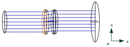
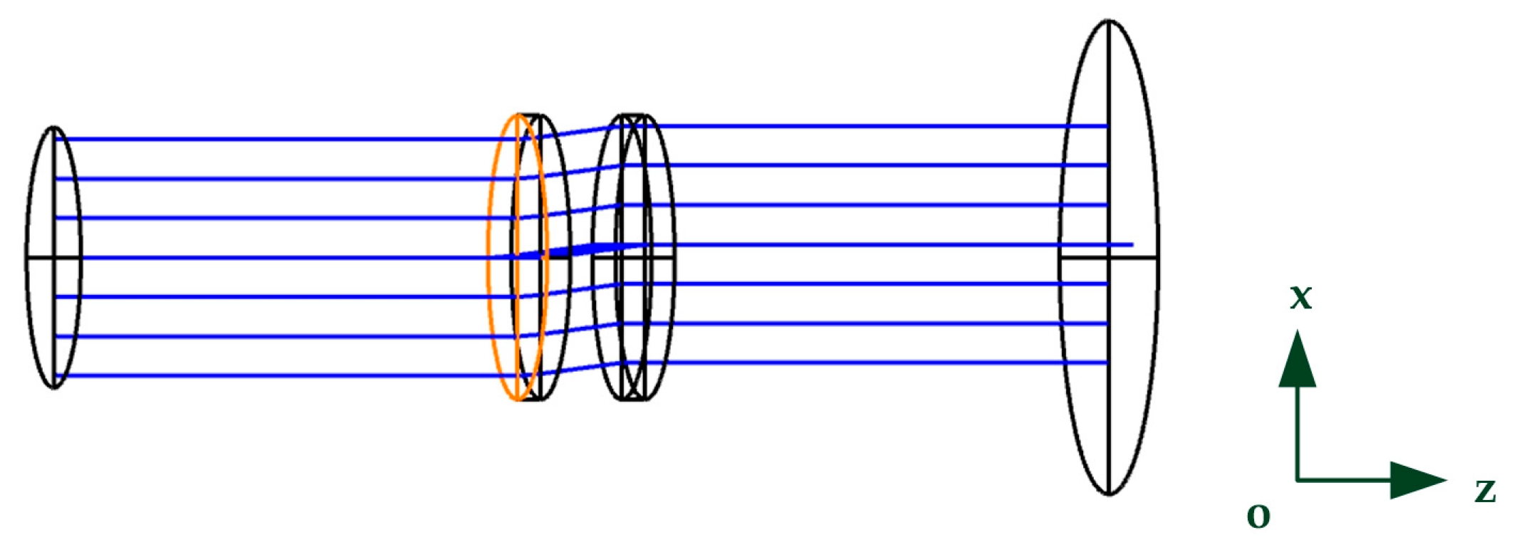
A double-grating optical design model is built in Zemax. Grating 1 and Grating 2 are placed in parallel; the Z-axis serves as the grating rotation axis, and the light beam propagates along the Z-axis. By performing ray tracing on the out beam, the direction cosines of the out beam are obtained; then, we derive the deflection angle and azimuth angle of the out beam. The 3D model of the optical design is shown in Figure 2.
Figure 2.
The optical model.
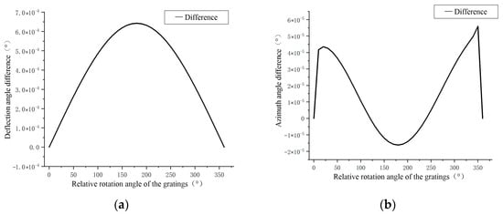
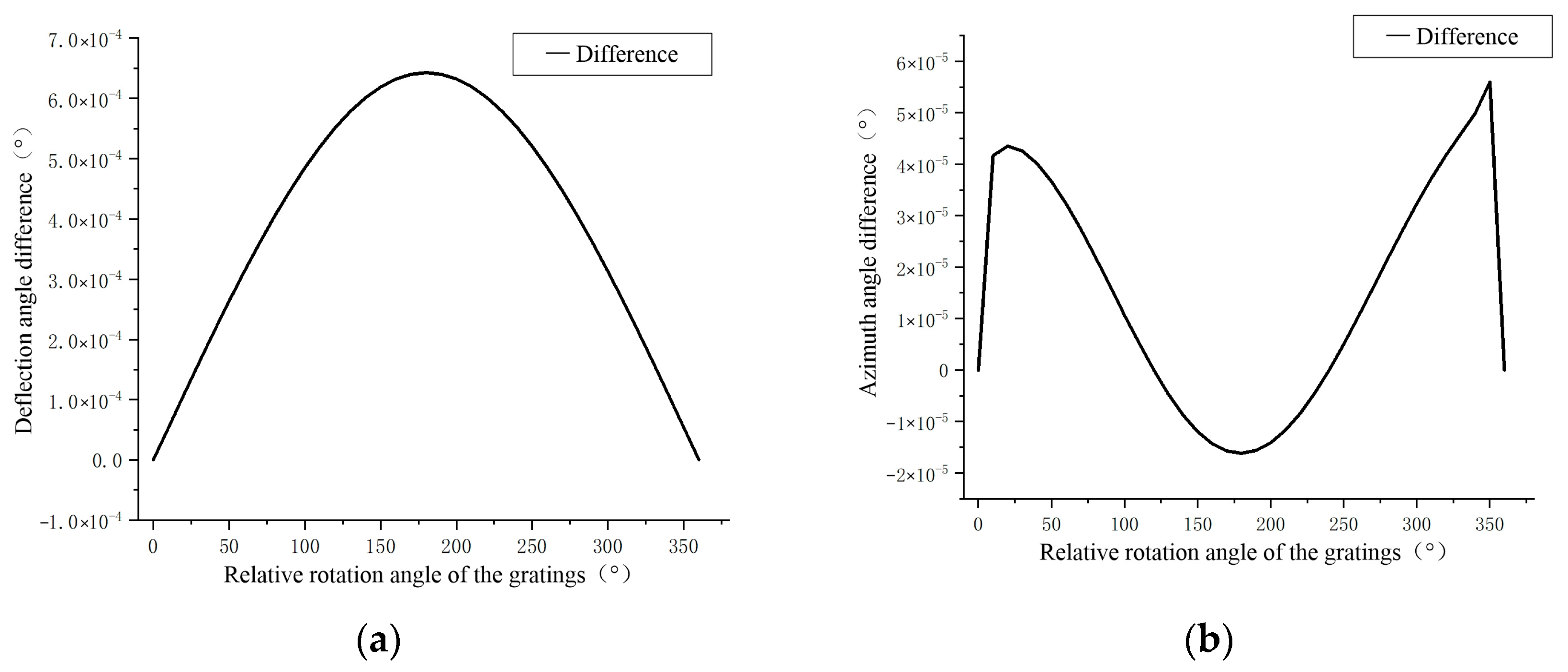
For the aiming model, the initial angle set to Grating 1 starts from 0° and increases by 10° up to 360°, while Grating 2 starts from 0° and increases by 20° up to 720°. The relative angle between Grating 1 and Grating 2 traverses 360° with a step of 2°. A beam oblique incidence model is established in MATLAB R2014a, and the data results obtained from the formula are compared with those from Zemax (https://www.ansys.com/products/optics/ansys-zemax-opticstudio, accessed on 12 January 2026). The target data obtained by formula is verified through analysis, and a graph of the differences between the target deflection angle and azimuth angle is plotted. As shown in Figure 3, the maximum error of the target deflection angle is 2.3″, and target azimuth angle is 0.2″.
Figure 3.
Difference diagram of aiming deflection angle and azimuth angle. (a) Deflection angle difference diagram. (b) Azimuth angle difference diagram.
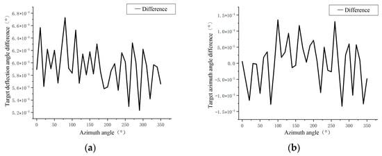
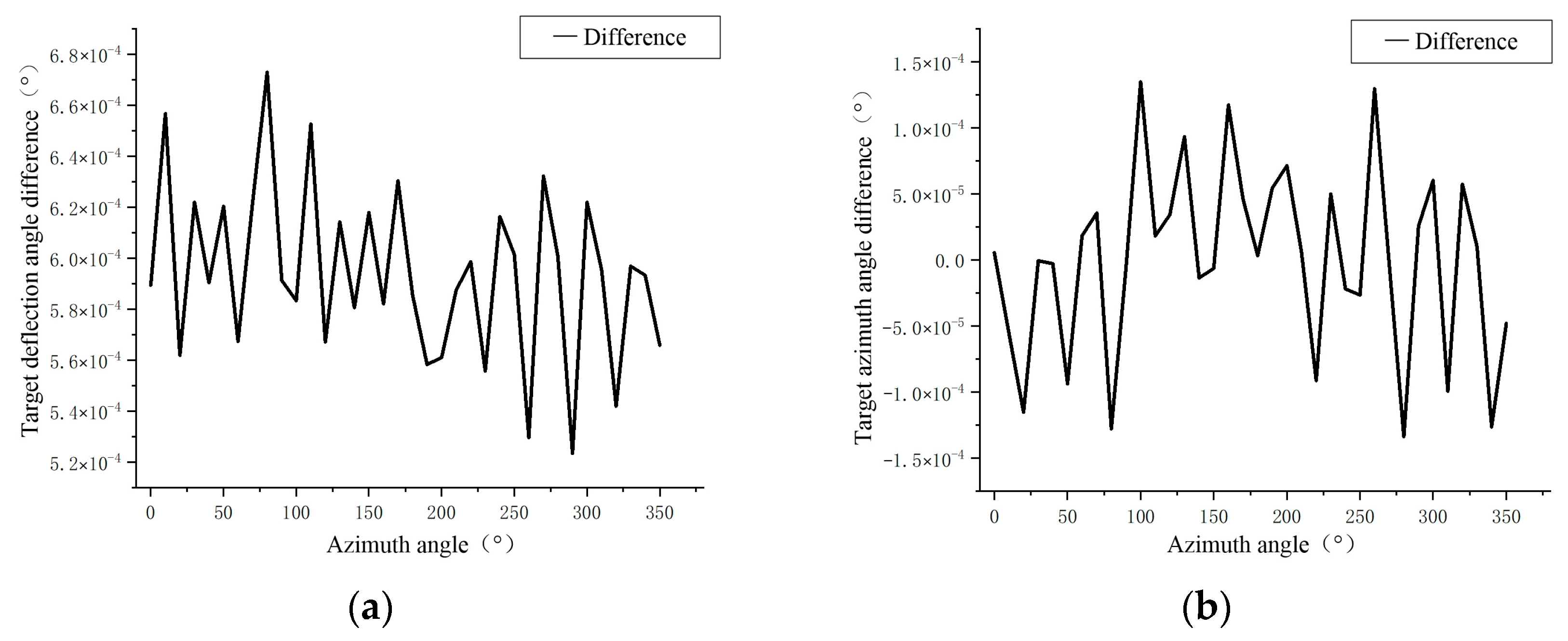
Target points are designed with an azimuth angle ranging from 0° to 360° within a 10° cone angle for tracking model. By comparing the error between the tracking optical angle in Zemax from the formula, a graph of the differences between the target deflection angle and azimuth angle is plotted. As shown in Figure 4, the maximum error of the target deflection angle is 2.4″ and the azimuth angle is 0.5″.
Figure 4.
Difference diagram of pointing deflection angle and azimuth angle. (a) Deflection angle difference diagram. (b) Azimuth angle difference diagram.
Analysis shows that the errors caused by the aiming and tracking formulas are relatively small, which fully meet the requirements of engineering applications.
2.2. Structure and Error Analysis of the Turntable
2.2.1. Error Sources
The main error sources of the double-grating aiming and tracking system are from parameter errors generated during grating production, as well as mechanical errors introduced by the mechanical system. Grating parameter errors are fixed systematic errors that can be eliminated through calibration, but mechanical errors consist of two parts: systematic errors such as the parallelism of the two axes and random errors such as the wobble precision of the shafting.
Grating period error is caused by inaccurate ruling periods during grating fabrication, which leads to deviations in the optical axis angle after passing through the grating. As a fixed value, it can be calibrated afterward. Grating tilt error refers to the inclination error between the theoretical optical axis of the grating and the mounting surface during processing, which affects the parallelism between the grating optical axis and the mechanical rotation axis during installation;, this error can also be calibrated. Among mechanical errors, the main errors include optical axis parallelism error caused by the non-parallelism of the two rotations, grating wobble error induced by shafting wobble, and grating rotation angle error resulting from the rotational measurement accuracy of the shafting. Among these, the optical axis parallelism error is a systematic error that can be calibrated after measurement. The grating wobble error and grating rotation angle error are random errors that directly affect precision, so these two errors are the focus of analysis.
2.2.2. Analysis of Grating Rotation Angle Error
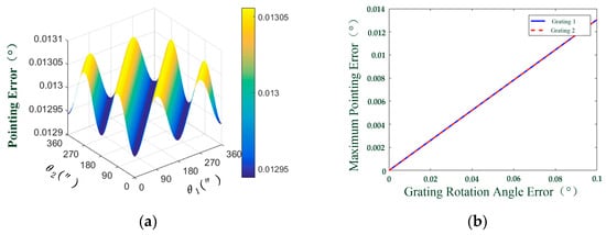
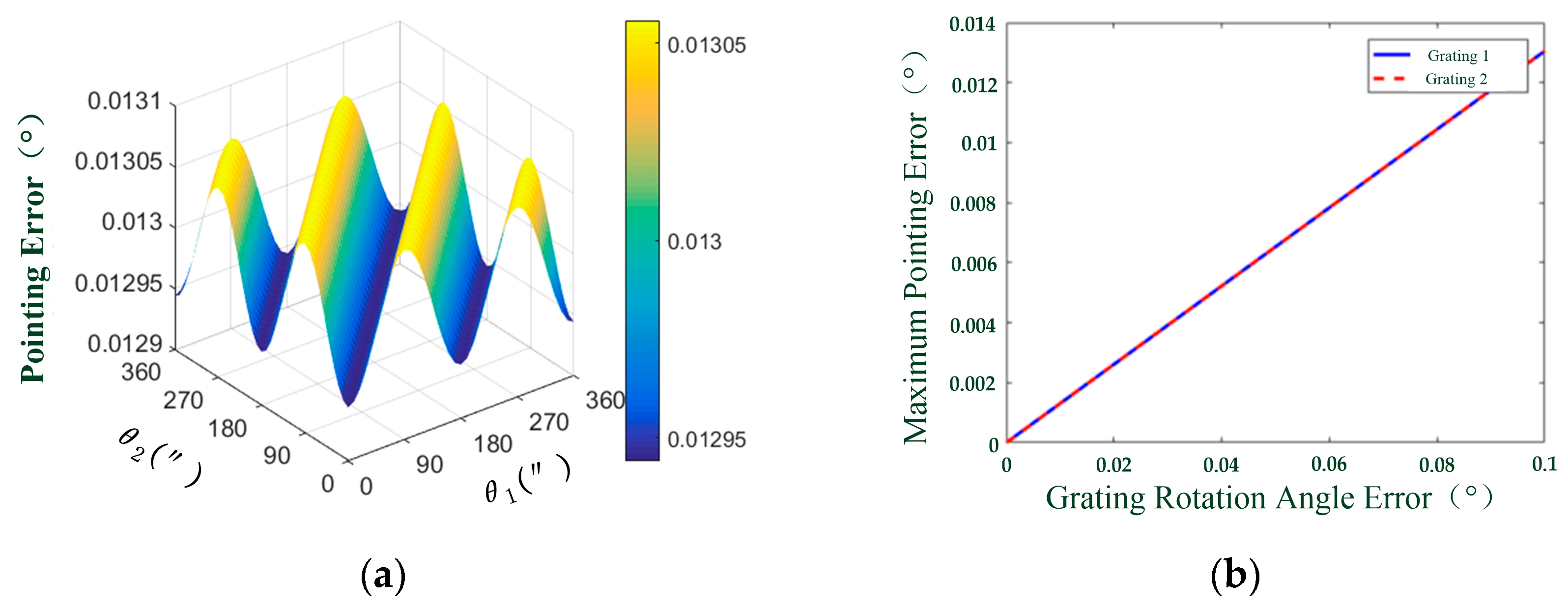
We analyzed the variation of the maximum pointing error when the measurement error of the double-grating rotation axis are change. A separate rotation angle error simulation is conducted for the two gratings; Figure 5a shows the changes in the optical axis error when the rotation angle errors δθ1 and δθ2 of the two gratings are 0.1°, and Figure 5b shows the change in the maximum optical axis error when the grating rotation angle error varies from 0.01° to 0.1°.
Figure 5.
Pointing error caused by grating rotation angle error. (a) Pointing error when δθ1 and δθ2 = 0.1°. (b) The maximum value of the optical axis error when the grating rotation angle error varies in the range of 0.01° to 0.1°.
The maximum optical axis error increases linearly with the variation rotation angle errors of the two gratings, and the slopes of their variation curves are the same. The pointing error caused by the grating rotation angle error is relatively large; further requirements should be imposed on the encoder accuracy and its installation accuracy in the design and alignment process.
2.2.3. Analysis of Grating Wobble Error
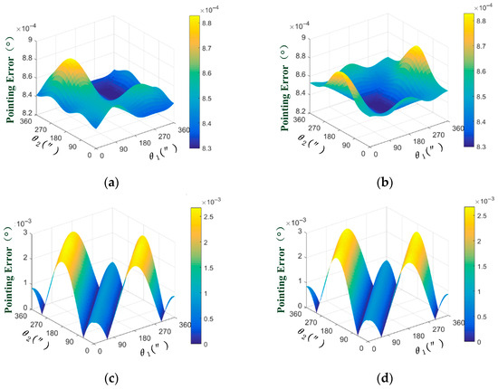
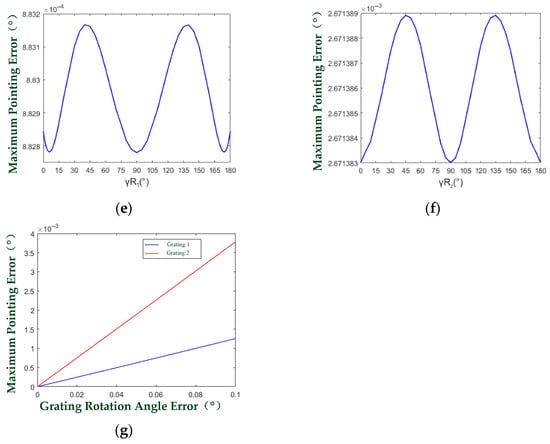
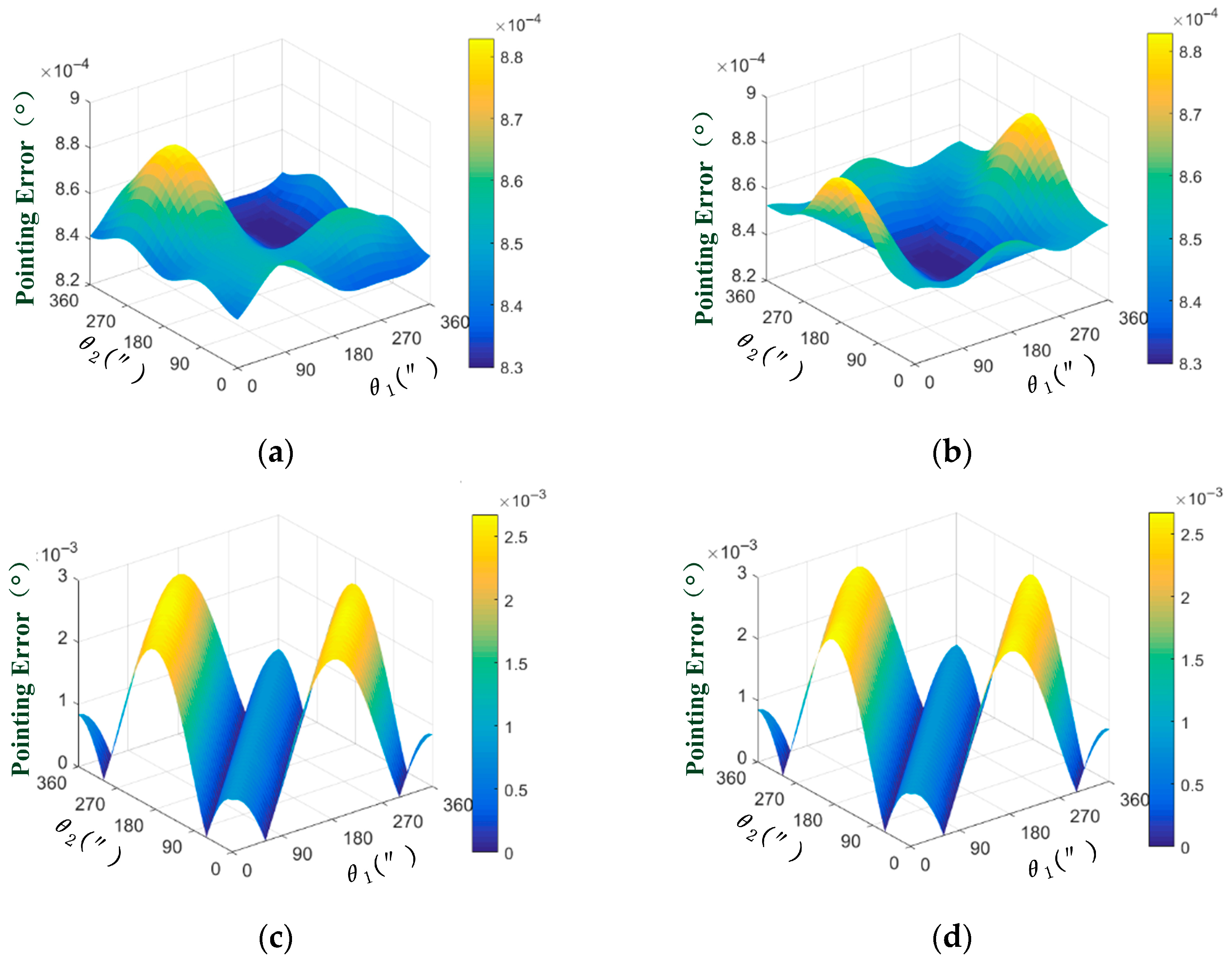
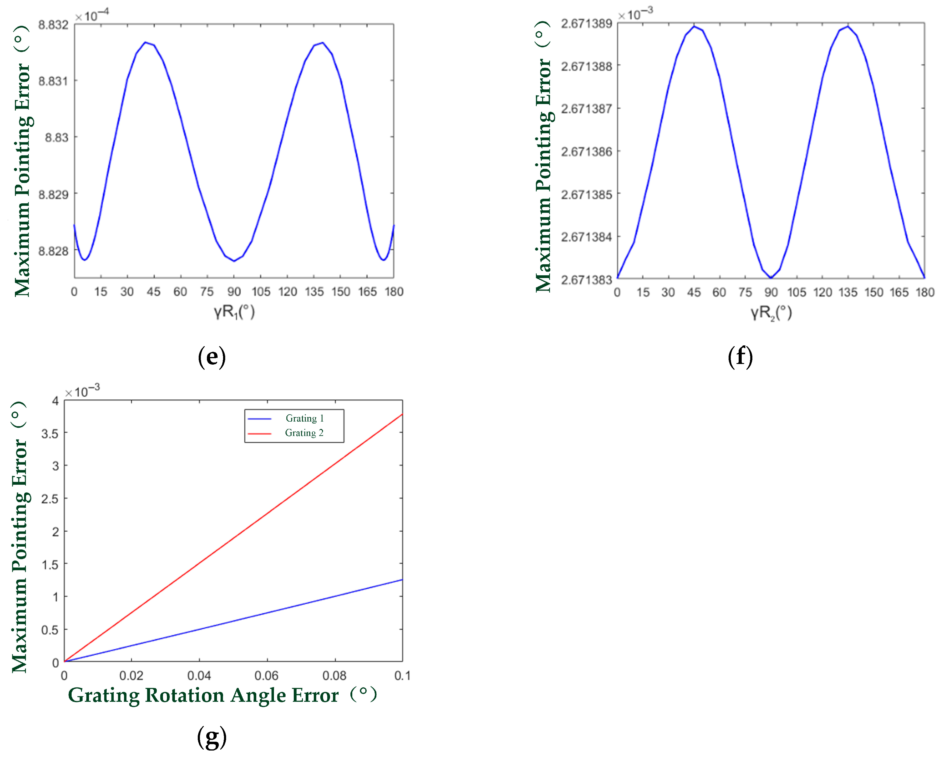
Since the double-grating aiming and tracking turntable has two grating axes, a separate deflection error analysis is conducted for each of the two grating axes, the rotation angles of the two gratings are denoted by θ1 and θ2, HRn denotes the grating horizontal axis and VRn denotes the grating vertical axis. As shown in Figure 6a,b they respectively illustrate the changes in pointing error within the pointing area when the tilt angle of Grating Axis 1 is fully allocated to the horizontal and vertical directions, with the tilt angle being 0.1° in both cases. Figure 6c,d show the corresponding changes in pointing error for Grating Axis 2, and Figure 6e,f presents the changes in the maximum pointing optical axis error when the tilt directions of the two grating axes change with the tilt angle also being 0.1°; the change angle of the tilt direction is represented by γR. Figure 6g shows the changes in the maximum pointing error when the tilt error angles of the two grating axes vary from 0.01° to 0.1°, as well as a comparison of their variation degrees.
Figure 6.
Pointing error caused by grating axis tilt error. (a) Pointing error when HR1 = 0.1°. (b) Pointing error when VR1 = 0.1°. (c) Pointing error when HR2 = 0.1°. (d) Pointing error when VR2 = 0.1°. (e) Maximum variation pointing error with γR1. (f) Maximum variation pointing error with γR2. (g) Variation in maximum pointing error with grating axis tilt error.
Analysis shows that when the tilt magnitude of the grating axes is fixed, changes in the tilt directions of both grating axes cause variations in the maximum pointing error, with the error reaching maximum values at 45° and 135°. When the tilt angle of the grating axes is constant, the maximum pointing error increases linearly with the two grating axes variations in the tilt magnitude. Additionally, the tilt magnitude of Grating Axis 2 has a greater impact on pointing precision than Grating Axis 1, with the ratio of their slopes being approximately 3:1. However, compared with the grating rotation error, the optical axis error caused by the grating axis tilt error is smaller.
2.2.4. Error Sensitivity Analysis and Error Allocation
Different error sources have varying impacts on the pointing error, by combining the error sources in the error model to analyze the sensitivity of errors, technical indicators for the machining and alignment precision of the double-grating aiming and tracking turntable are proposed. The weight of each error in the entire system is shown in Table 1 below.
Table 1.
Influence of error sources on pointing error.
It can be seen from Table 1 that the sensitivity of pointing errors caused by various error sources follows the order Light Source Tilt Error > Grating Rotation Angle Error > Grating Axis Tilt Error = Grating Tilt Error. From the above analysis results, the error proportion of each error source relative to a 0.1° variation is as follows:
Among them, L, R1, R2, P1, P2, Q1, and Q2 respectively represent light source tilt, Grating Axis 1 tilt, Grating Axis 2 tilt, Grating 1 tilt, Grating 2 tilt, Grating 1 rotation angle error, and Grating 2 rotation angle error among the error sources. From Formula (13), the formula for calculating total error allocation can be derived as follows:
The sum of all variation proportions is as follows:
We calculated the error values that need allocated to each error source with Formula (16):
Since the pointing errors caused by various error sources are all in equal proportion, the error sources are calculated according to the error proportion:
Based on the overall index requirement that the pointing error δe ≤ 10″, error allocation is performed for the double-grating aiming and tracking turntable. The results of each pointing error and its corresponding error source allocation are summarized in Table 2, and the allocated system error sources corresponding to the errors of the double-grating aiming and tracking turntable are shown in Table 3.
Table 2.
Allocation of error sources.
Table 3.
Errors of double-grating tracking turntable corresponding to system error sources.
2.3. System Error Compensation
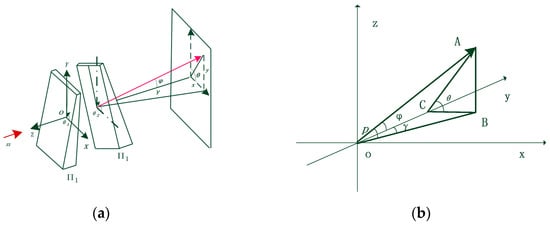
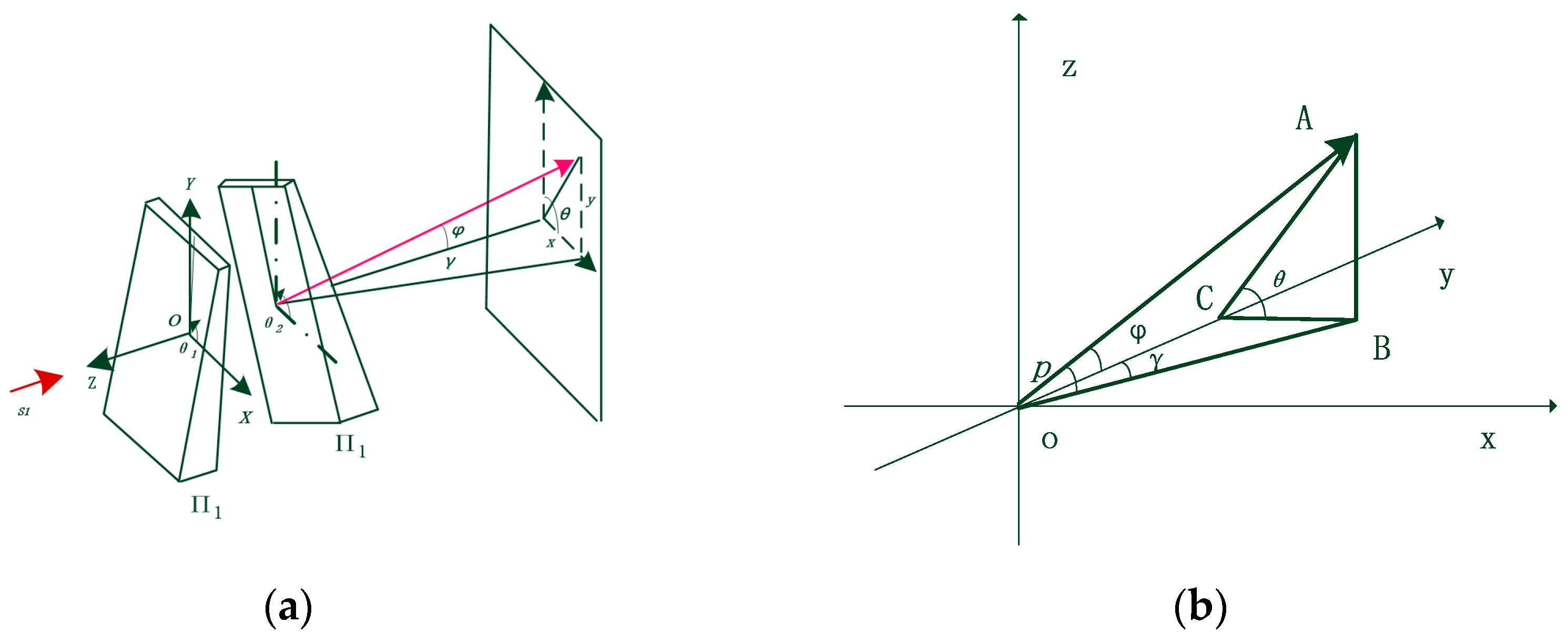
As shown in Figure 7a the structural model is established to integrate the coordinate system of the rotating axis with that of the detection axis, and the model is used to compensate for system errors, thereby reducing the optical axis error of the system. θ1 and θ2 are the rotation angles of the gratings, Υ and θ are the azimuth and elevation angle of the light.
Figure 7.
Schematic diagram of double-grating decoupling. (a) Model of double-grating decoupling (b) Diagram of the model.
According to the schematic diagram of the model as shown in Figure 7b, we derive the following derivation to obtain the decoupled mathematical model:
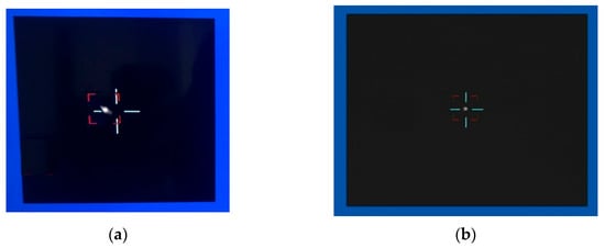
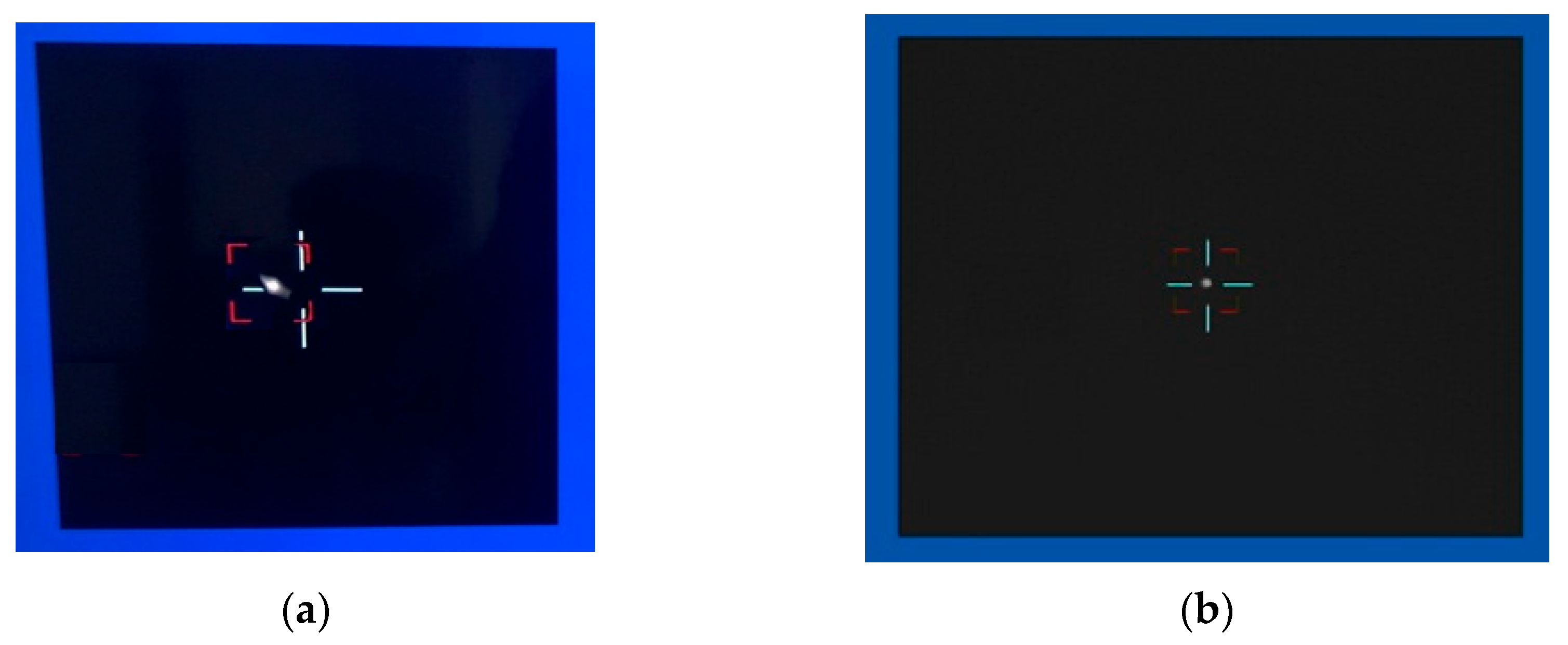
After compensation using the decoupled model, the pointing position accuracy of the system is significantly improved. The experimental results are shown in Figure 8; the off-axis error is greatly reduced after compensation.
Figure 8.
Result images before and after compensation. (a) Result before compensation. (b) Result after compensation.
2.4. Tracking Accuracy Analysis
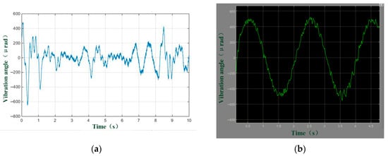
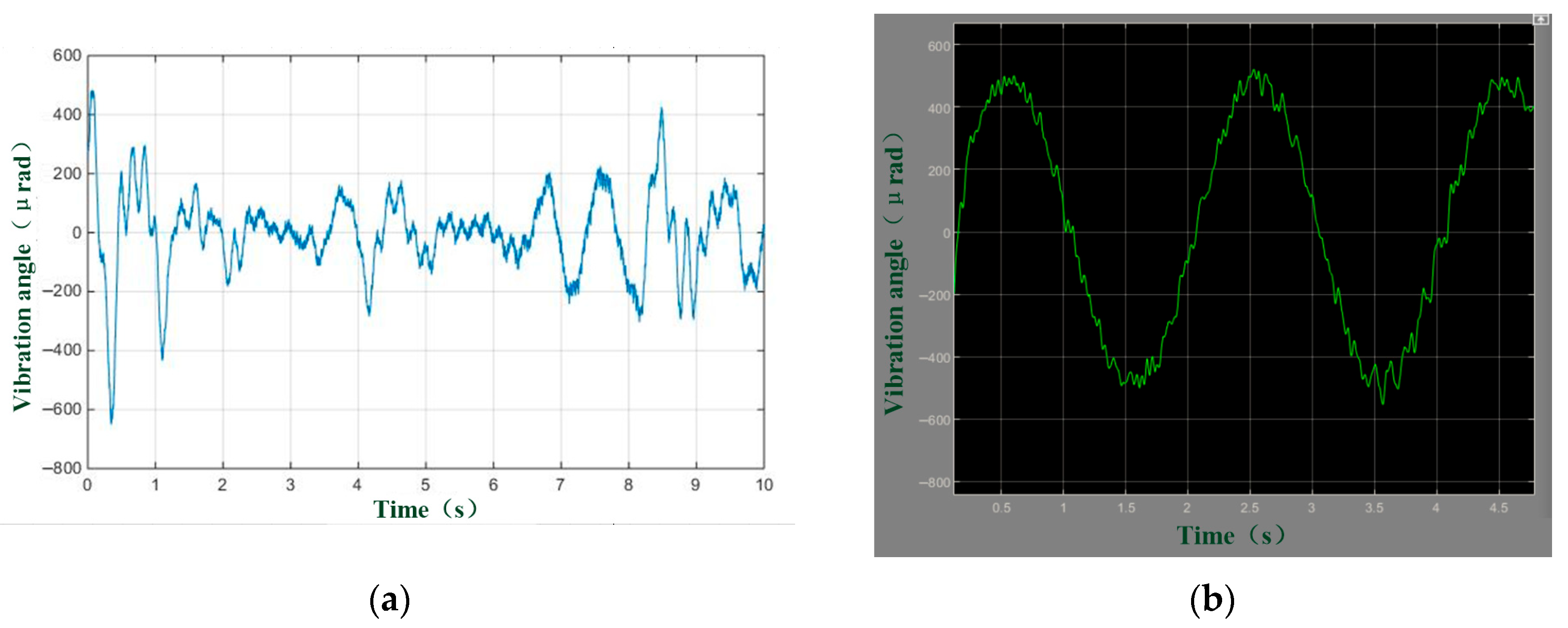
During system operation, based on the real-time target position acquired by the image sensor, servo closed-loop tracking is adopted to actively compensate for the vibration and disturbance of the aircraft platform, thereby achieving target tracking with a certain precision. The servo tracking accuracy is simulated,, the attitude disturbance input to the system is simulated by a sinusoidal signal with an amplitude of 2° and a frequency of 0.5 Hz to represent the attitude disturbance of the aircraft platform. Meanwhile, the angular vibration signal after the shock absorber provided by the general system was superimposed. This vibration angle signal served as the vibration disturbance source, as shown in Figure 9a. The closed-loop tracking bandwidth of the grating optical system is 3 Hz. Under the servo closed-loop condition, the following error of the system is approximately 344.5 μrad, as shown in Figure 9b. Considering the image target position detection error δ1 = 15.6 μrad, system random error δ2 = 50 μrad and following error δ3 = 415.5 μrad. Comprehensively, the system accuracy is approximately 418.7 μrad.
Figure 9.
Tracking accuracy analysis. (a) Input angular vibration. (b) Following error.
2.5. Aiming and Tracking Turntable
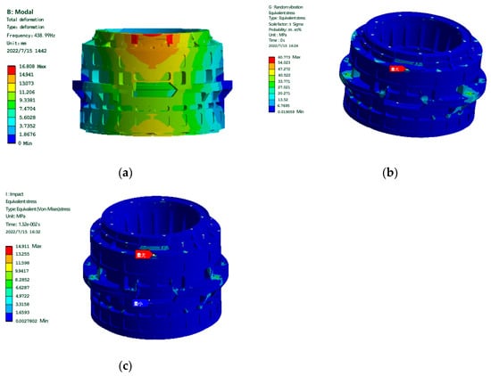
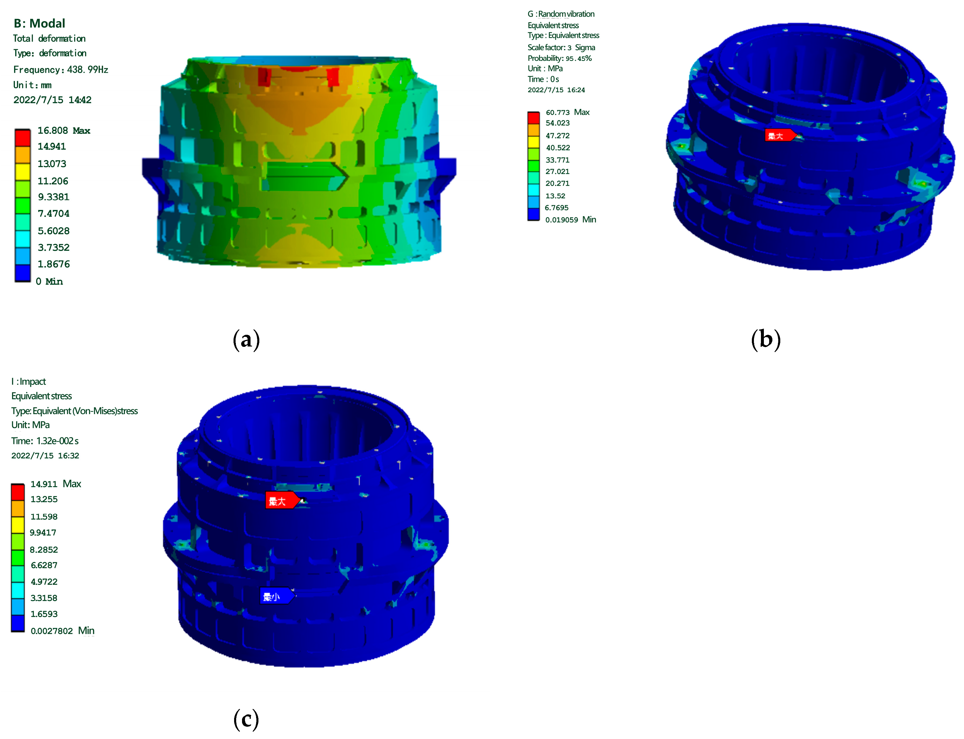
Based on the above theoretical analysis, the error requirements of the mechanical turntable are determined. The mechanical tracking turntable is designed as a structure of two independent single-axis systems. Each rotating axis drives grating to rotate fully around the circumference, ensuring that the two Risley gratings can rotate independently within a 360° range. During the design process, modal analysis, random vibration analysis and shock analysis were performed on the structure. As show in Figure 10a, the first-order mode of the structure is about 438 Hz. Under the combined action of 6 G (rms) random vibration in three directions, the structural stress is small; as show in Figure 10b, the maximum stress is 60.773 MPa. Under a 20 G impact load, the maximum stress of the system is 14.9 MPa; the result is shown in Figure 10c. The analysis shows that the structural strength meets the airborne mechanical requirements.
Figure 10.
Results of finite element analysis. (a) Modal analysis. (b) Random vibration analysis. (c) Shock analysis.
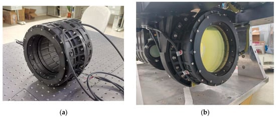
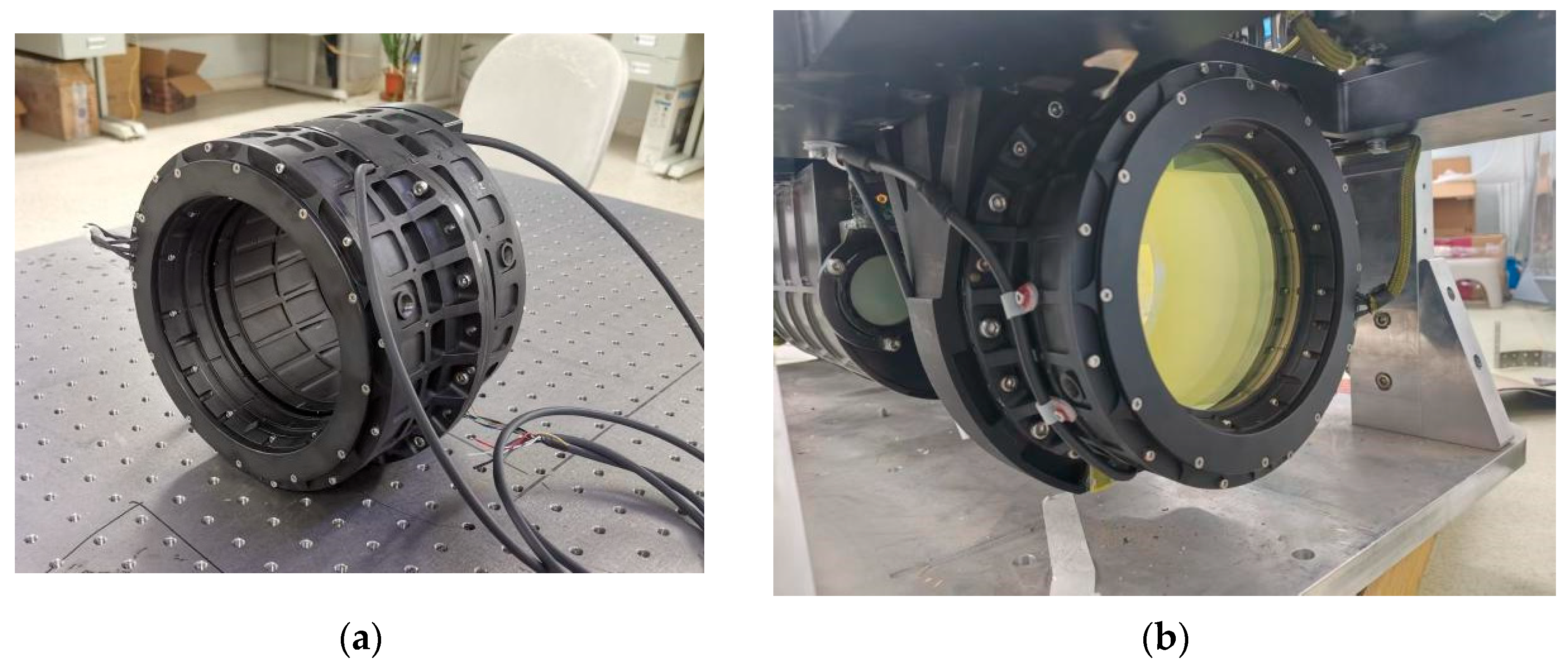
The grating coarse tracking turntable is shown in Figure 11. The system has a clear aperture greater than 120 mm, an overall size less than Φ190 mm × 155 mm, and a weight of 9.5 kg.
Figure 11.
Coaxial mechanical turntable. (a) Without grating. (b) With grating.
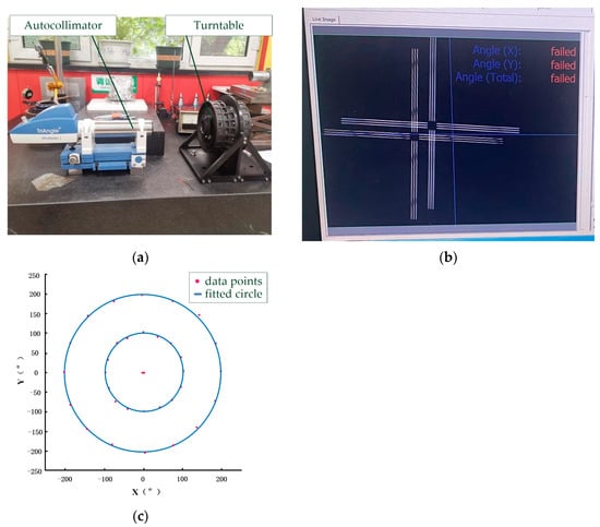
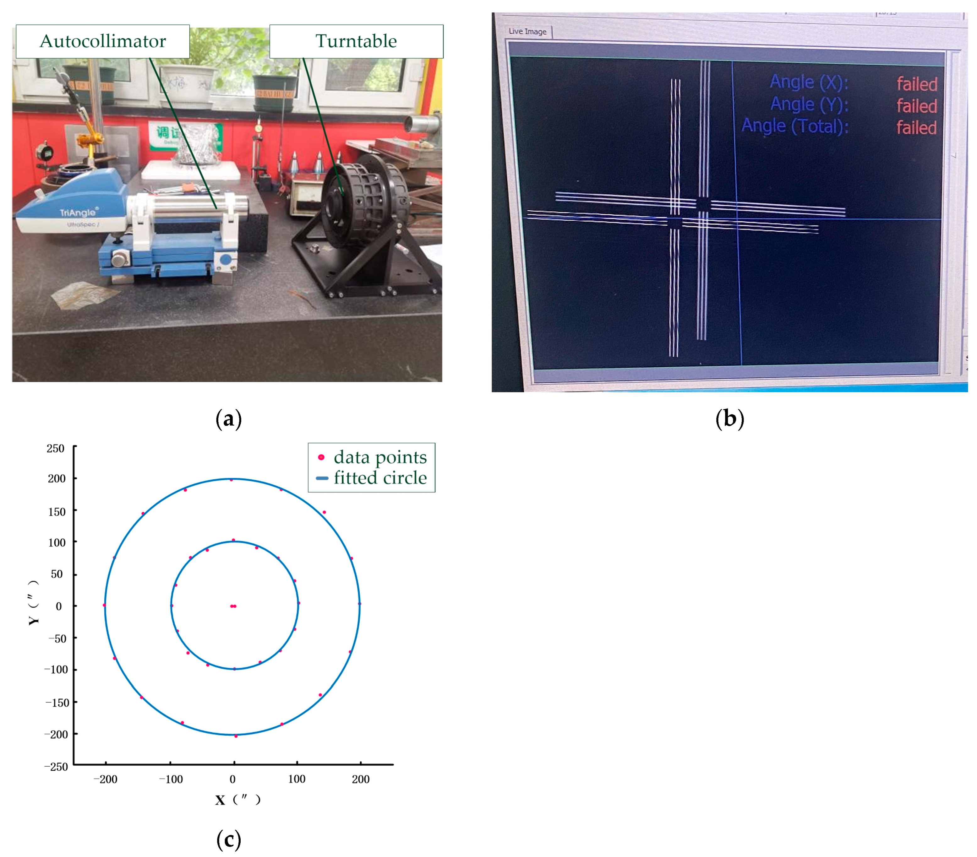
To verify the parallelism of the two rotating axes of the turntable, as show in Figure 12, an optical detection method based on a semi-transparent and semi-reflective reference mirror is proposed [13]. During the test, the positions of the turntable and the autocollimator are fixed, a semi-transparent and semi-reflective reference mirror is mounted on the axis close to the autocollimator and ordinary reference mirror is installed on another axis. When the transmission surface is blocked, the axis position of Axis 1 is measured, then the transmission surface is unblocked and the reflection surface is blocked; the axis position of Axis 2 is tested by transmitting through the transmission surface of the semi-transparent and semi-reflective mirror, then passing through the reference mirror inside Axis 2. Finally, the parallelism of the two axis is obtained by calculating the position difference between the centers of the two fitted circles.
Figure 12.
Axis system parallelism test. (a) Test site. (b) Imaging of the reference mirror and semi-transparent and semi-reflective mirror (when the semi-transparent and semi-reflective mirror is unblocked). (c) Test results.
The parallelism of the two axis systems and their comparison with the error allocation design values are shown in Table 4; the parallelism of the two axis systems is 2.31″.
Table 4.
Parallelism of the two axis systems.
Axis system precision was tested using the photoelectric autocollimator; the detection results as well as their comparisons with the error allocation design values are shown in Table 5. Based on the average value of three measurements, the runout of Axis System 1 is 2.90″and Axis System 2 is 3.04″.
Table 5.
Axis system runout error.
3. Results
3.1. Pointing Error Testing
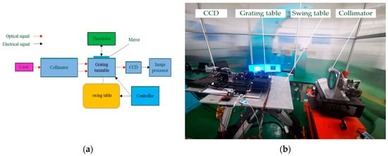
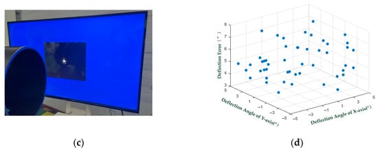
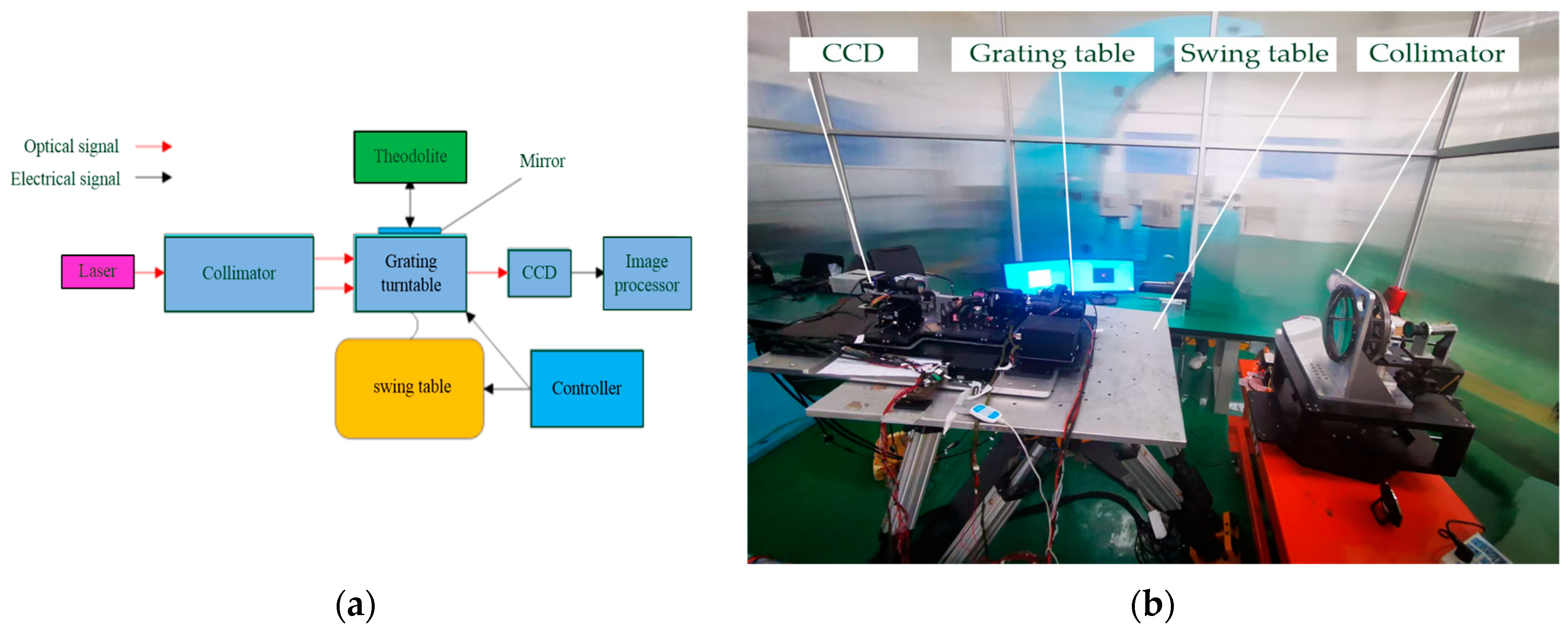
Figure 13a shows the schematic diagram of the test; the test equipment consists of collimator, grating turntable, test camera and 6-degree-of-freedom swing table. Figure 13b shows the field test diagram; the swing table deflects according to the pointing angle, and the angle of the swing table is measured by the theodolite. Subsequently, the grating turntable performs the same pointing angle as the swing table, then the pointing error can be measured by the camera. Within the working range of ±5°, Figure 13c,d show the test spot andpointing error results; 50 pointing error tests under different pointing angles were carried out, the maximum pointing error is 7.2″.
Figure 13.
Pointing error testing. (a) Test principle block diagram. (b) Test site. (c) Camera image. (d) Pointing error results.
3.2. Tracking Accuracy
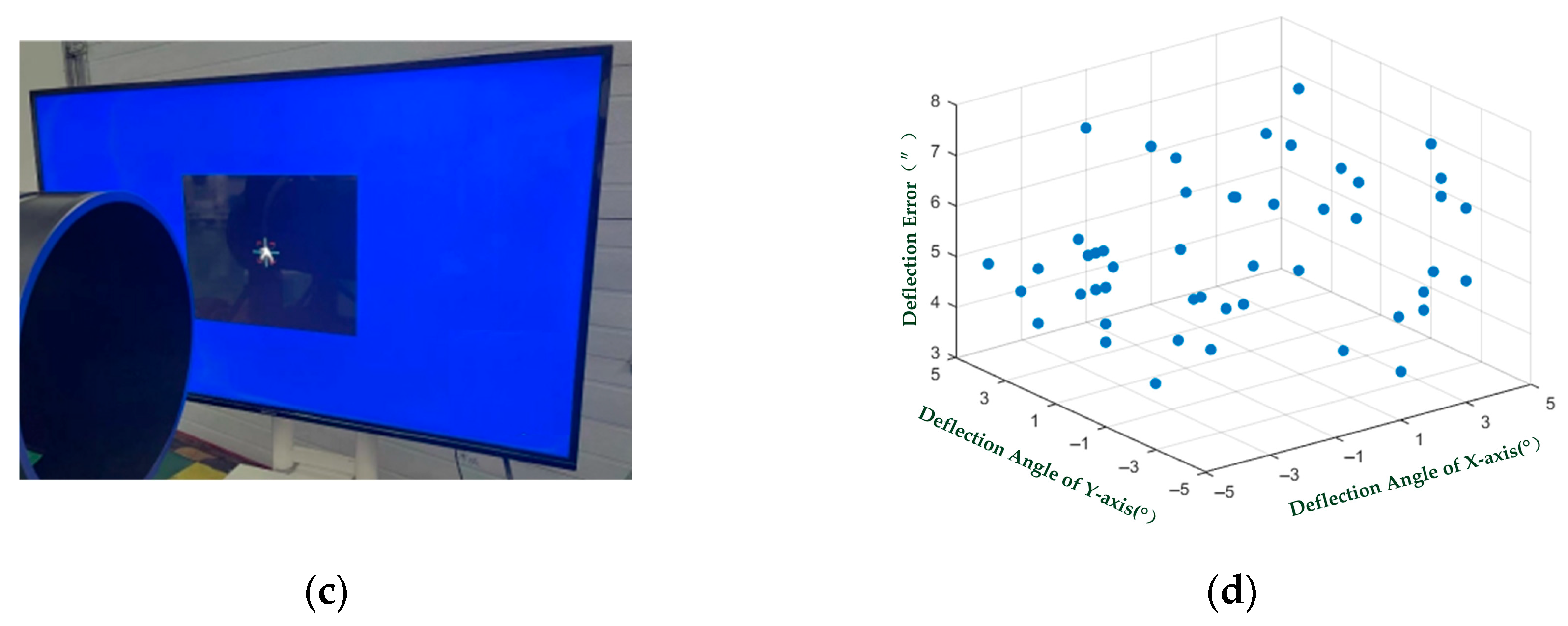
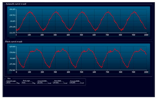
The swing table oscillates with an equivalent sine wave of 2°@0.5 Hz, and the coarse tracking accuracy is obtained by statistically analyzing the data derived from the off-target amount. As shown in Figure 14, the combined accuracy of the two axes for coarse tracking is 370.4 μrad (1σ). Considering that there is no external vibration error during the test and the tracking accuracy is approximately 70 μrad in the subsequent tracking test under vibration conditions completed with the general system, the experimental tracking accuracy of the system is basically consistent with the analysis results.
Figure 14.
Curve of coarse tracking accuracy.
According to the reviewed literature, the system proposed in this paper is compared with similar coaxial systems. As shown in Table 6, we can see that the proposed system has a significant advantage in the aperture–size ratio, especially in terms of weight. Compared with foreign systems of similar aperture, the weight of our system is much lower.
Table 6.
Performance parameter comparison.
3.3. Outdoor UAV Tracking Experiment
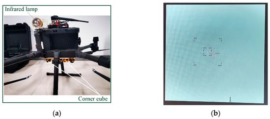
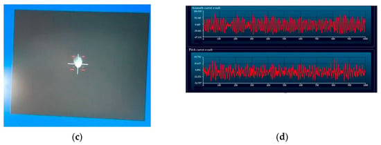
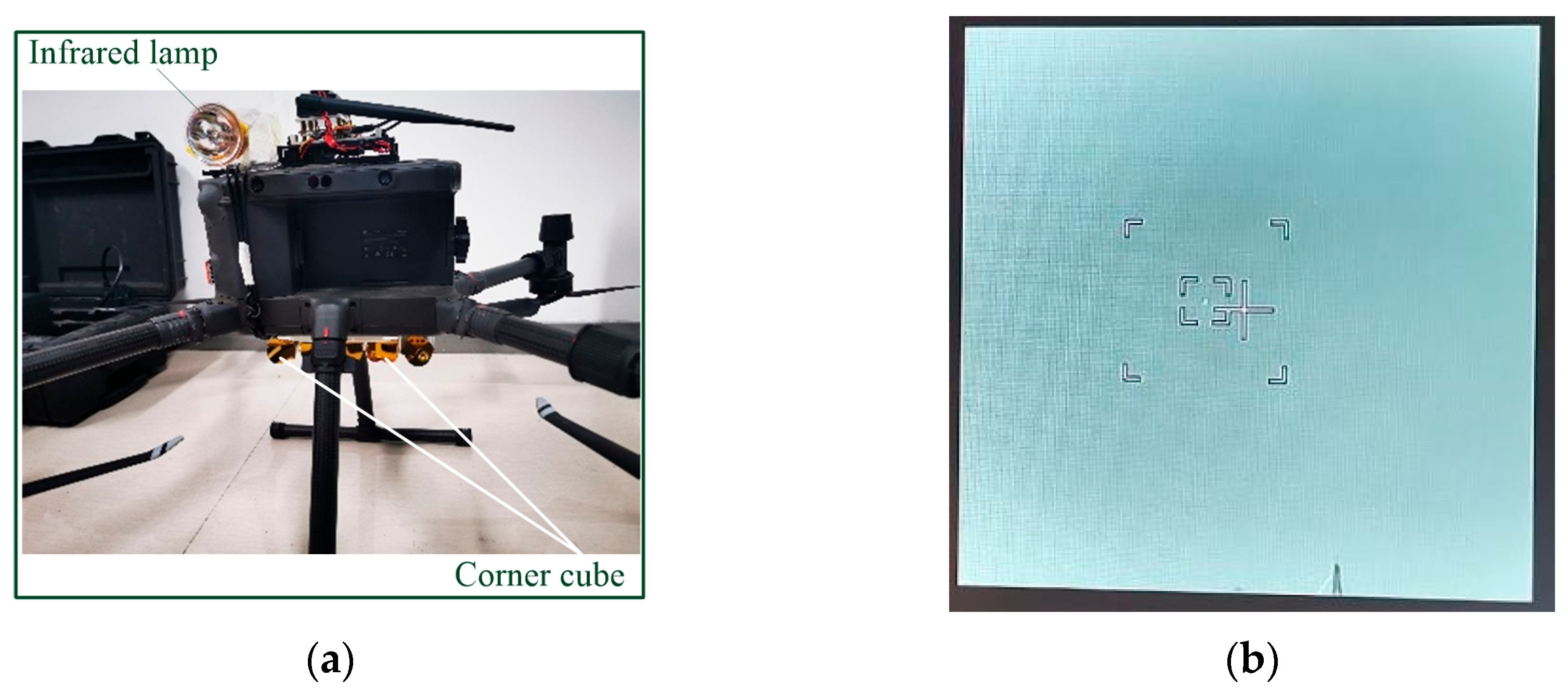
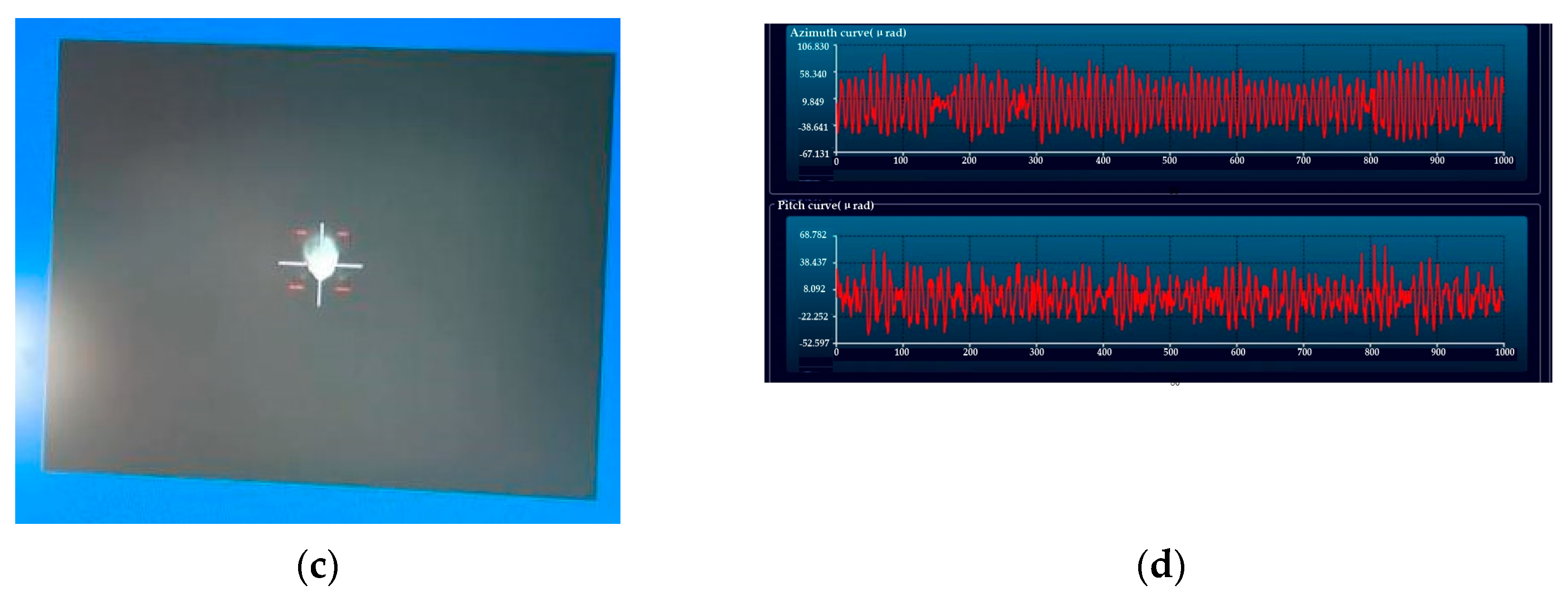
The aiming/tracking system of this paper is the coarse tracking component of the integrated system; the integrated system is mounted on a fixed-wing aircraft in practical applications to aim and track dynamically flying targets. In the previous section, a six-degree-of-freedom motion table was used to verify the tracking performance under the motion of the carrying platform. Then, to verify the system’s tracking ability for dynamic targets, UAV tracking tests were conducted to verify the tracking performance of the system. A UAV with an infrared target source and a reflecting corner cube was used as the tracking target to simulate the actual working scenario of the system. The field test scenario is set up identically to the actual target tracking condition of the system; during the experiment, the integrated system containing aiming/tracking system of this paper was installed on the top of the building to ensure an unobstructed field of view. An infrared lamp and a corner cube were installed on the UAV as the tracking target for the integrated system, as shown in Figure 15a. The infrared lamp provided an infrared tracking target for the illumination system. The illumination laser is emitted after the illumination system tracked the target then laser will be reflected by the corner cube, the grating turntable captured and tracked the reflected laser. The system conducted tests on the UAV target located beyond 3 km. The infrared image and grating tracking image are shown in Figure 15b,c In the field test, the flight stability of the UAV was much better than the parameters of the swing table during the test, so its tracking accuracy is better than the test index. The test results show that the combined coarse tracking accuracy was 160 μrad (3σ); the result is shown in Figure 15d.
Figure 15.
Outdoor experiment. (a) UAV physical diagram. (b) Infrared image. (c) Grating tracking image. (d) Three-kilometer tracking accuracy curve.
4. Discussion
The grating features light weight, a thin structure, and no rotational eccentricity. Its function is consistent with that of an optical wedge when dealing with polarized light. Based on the characteristics of the grating, we focused on the research of an aiming and tracking system based on Risley gratings.
First, the theoretical errors of the system were analyzed, the tracking model and pointing model were established, and the model errors of the tracking model and pointing model as well as the influence of various errors in the system on precision were investigated. Meanwhile, a correction model was proposed for the system errors, and the tracking precision of the system was analyzed.
Then, a coaxial tracking turntable based on polarizing grating was developed, according to the mathematical and physical analysis; the design precision requirements of the mechanical turntable were determined, and a coaxial mechanical servo turntable based on gratings was designed. Mechanical simulations such as random vibration and shock were carried out on the turntable to verify its adaptability to the airborne environment.
Subsequently, the mechanical servo turntable was fabricated with an optical aperture greater ≥120 mm, an overall size ≤ Φ190 mm × 155 mm, and a weight of 9.5 kg, and a parallelism testing method based on a beam-splitting tooling mirror was proposed, solving the difficult problem of coaxiality testing for the turntable, then measuring the coaxiality and axis system accuracy of the dual-axis turntable.
Finally, indoor performance tests and field UAV experiments were conducted. Pointing accuracy tests, dynamic tracking accuracy tests, and outdoor UAV tracking tests were carried out. The system’s pointing accuracy is less than 10 arcseconds, the dynamic tracking accuracy is approximately 370 μrad (1σ), and the outdoor UAV tracking accuracy is approximately 160 μrad (3σ). The system has the advantages of small size, light weight, large optical aperture, and high tracking accuracy.
There are few relevant research reports on grating systems, and they have greater potential to become more lightweight and compact servo tracking systems. This paper conducts a thorough analysis and research on the grating-based system throughout the entire process, including theoretical analysis, error allocation, structural design, finite element simulation, accuracy analysis, index testing scheme, and field experiments. It has certain theoretical and engineering significance for promoting the application of grating tracking systems.
Author Contributions
Conceptualization, X.L.; methodology, L.J.; data curation, T.W.; writing—original draft preparation, H.W.; writing—review and editing, S.Y.; funding acquisition, K.D. All authors have read and agreed to the published version of the manuscript.
Funding
This research was funded by Mobile Information Networks-National Science and Technology Major Project, grant number 2025ZD1302900.
Data Availability Statement
Data are contained within the article.
Conflicts of Interest
The authors declare no conflict of interest.
Abbreviation
The following abbreviation is used in this manuscript:
| UAV | Unmanned Aerial Vehicle |
References
- Hakun, C.; Budinoff, J.; Brown, G.; Parong, F.; Morell, A. A Boresight Adjustment Mechanism for Use in Laser Altimeters. In Proceedings of the 37th Aerospace Mechanisms Symposium, Galveston, TX, USA, 19–21 May 2004; NASA Goddard Space Flight Center: Greenbelt, MD, USA, 2004. [Google Scholar]
- Michael, S.; David, G. Control laws for a three-element Risley prism optical beam pointer. In Free-Space Laser Communications VI; SPIE: Bellingham, WA, USA, 2006; Volume 6304, pp. 16–22. [Google Scholar]
- Ostaszewski, M.; Harford, S.; Doughty, N.; Hoffman, C.; Sanchez, M.; Gutow, D.; Pierce, R. Risley prism beam pointer. In Free-Space Laser Communications VI; SPIE: Bellingham, WA, USA, 2006; Volume 6304, pp. 45–54. [Google Scholar]
- Clark, C.S.; Gentile, S. Flight miniature Risley prism mechanism. In Novel Optical Systems Design and Optimization XII; SPIE: Bellingham, WA, USA, 2009; Volume 7429, pp. 147–154. [Google Scholar]
- Lavigne, V.; Ricard, B. Fast Risley prisms camera steering system: Calibration and image distortions correction through the use of a three-dimensional refraction model. Opt. Eng. 2007, 46, 043201. [Google Scholar] [CrossRef] [Scilit]
- Yu, H.; Bao, Z.; Wang, X.; Zha, R.; Yang, Y.; He, R. XY-2 satellite laser communication equipment PAT test in orbit. Infrared Laser Eng. 2021, 50, 237–244. [Google Scholar]
- Liu, Z.; Zhang, F.; Hong, X. Low-cost retina-like robotic lidars based on incommensurable scanning. IEEE/ASME Trans. Mechatron. 2021, 27, 58–68. [Google Scholar] [CrossRef] [Scilit]
- Hong, H.; Zhou, Y.; Tao, Z.; Fan, D.; Fan, S. Application of Risley prism on optical reconnaissance. J. Appl. Opt. 2014, 35, 179–187. [Google Scholar]
- Song, Y. Key Technology Research of Coarse Pointing Mechanism for Laser Communication Based on Risley Prisms. Ph.D. Thesis, University of Chinese Academy of Sciences, Changchun, China, 2023. [Google Scholar]
- Chen, W. Research on Beam Steering Technology of High-Efficiency Broadband Liquid Crystal Risley Gratings. Ph.D. Thesis, University of Chinese Academy of Sciences, Changchun, China, 2022. [Google Scholar]
- Li, S. Design of Liquid Crystal Risley Grating and Study of Its Beam Deflection Characteristics. Ph.D. Thesis, University of Chinese Academy of Science, Changchun, China, 2019. [Google Scholar]
- Zhou, Y.; Fan, D.; Fan, S.; Chen, Y.; Liu, G. Laser scanning by rotating Risley gratings. Appl. Opt. 2016, 55, 5149–5157. [Google Scholar] [CrossRef] [Scilit] [PubMed]
- Li, X.; Zhu, G.; Guo, M.; Liu, Y.; Zhang, C. Coaxiality measurement and uncertainty analysis of rotating shafts based on autocollimation. Infrared Laser Eng. 2023, 52, 312–323. [Google Scholar]

Disclaimer/Publisher’s Note: The statements, opinions and data contained in all publications are solely those of the individual author(s) and contributor(s) and not of MDPI and/or the editor(s). MDPI and/or the editor(s) disclaim responsibility for any injury to people or property resulting from any ideas, methods, instructions or products referred to in the content. |
© 2026 by the authors. Licensee MDPI, Basel, Switzerland. This article is an open access article distributed under the terms and conditions of the Creative Commons Attribution (CC BY) license.