


Abstract
Planar mirrors play a crucial role in autocollimation testing and optical beam relay systems of telescopes and other fields. However, for the next-generation large-aperture telescopes, typical monolithic planar mirrors fall short in meeting anticipated performance requirements, owing to their high costs and fabrication limitations. Here, a new integrated multimodal testing method for 3–4 m-class segmented planar mirrors is proposed. The presented system utilizes an innovative keystone architecture with a central mirror and keystone-shaped segments, which is superior to the traditional hexagonal architecture. To facilitate rapid coarse alignment, a machine vision system based on edge detection is investigated. Furthermore, the dispersed fringe technique is used for robust co-phasing. By using a segmented planar mirror designed with sub-aperture stitching strategy and combining local apertures, the system cost was reduced and high-precision measurement was achieved. Eventually, the alignment, co-focus and co-phasing measurements based on the proposed concept were completed, and the transfer characteristics were determined by analyzing the Optical Transfer Function (OTF). Test data shows co-phasing accuracy of better than 30 nm RMS (root-mean-square) and alignment accuracy less than 10 arcseconds. In addition, the system uses small-aperture mirrors in autocollimation testing to facilitate flexible alignment and testing of individual segments. The test optical path is configured to match the effective focal length of the system under test, and the optical lever effect of reflectors enhances the alignment sensitivity. The method combines autocollimation and wavefront sensing which allows the approach to provide high-precision control of co-focus, co-phasing, and surface errors correction.
1. Introduction
The progress of modern astronomy continually demands enhanced spatial resolution and detection sensitivity in optical systems. As described by the Rayleigh criterion, the resolution of the optical system is inversely related to its aperture diameter, the detection sensitivity is proportional to the light-gathering area. Consequently, the essential method for improving optical system observational capabilities is to increase the telescope aperture diameter.
The future large-aperture telescopes are expected to bring revolutionary discoveries in frontier scientific fields (such as observing active galactic nucleus, exploring the origin of the universe and detecting the universe’s first light), which also brings about the demand for high-performance systems [1]. In this case, the application of planar mirrors is crucial for integrating detection and efficient light relay.
Large-aperture planar mirrors are critical for beam steering and relay capabilities, primarily serving two fields: optical testing and optical beam relay. The Thirty Meter Telescope (TMT), which is under construction, has a giant, elliptical planar mirror measuring 3.5 by 2.5 m [2,3]. This mirror can precisely direct the light collected by the primary mirror for fiber relay to various scientific instruments on the Nasmyth platforms. The Keck Telescope has also designed a deployable, dual-layer tertiary mirror system for Keck 1 telescope. Its primary function is to direct light from the secondary mirror to any of the six focal stations (two Nasmyth and four bent Cassegrain) [4].
Currently, the largest monolithic planar mirror remains in the 4 m class, failing to meet the requirements of future large-aperture telescopes. Meanwhile, manufacturing of the 8 m-class monolithic and 30 m-class segmented mirrors needs larger planar mirrors for optical beam routing and autocollimation testing [5,6,7]. To address the limitations of current automated collimation testing in large-scale optical systems, a new segmented planar mirror approach is proposed. Compared to conventional hexagonal segmentations used in telescopes like JWST, the implemented annular shape suppresses structured diffraction spikes as well as achieves spatial frequency coverage uniformity of great importance for integration tests [8].
Accurate wavefront control is essential for mitigating the influence of low-order errors in the process of steering large-aperture planar mirrors. The Large Sky Area Multi-Object Fiber Spectroscopic Telescope (LAMOST) is equipped with a hexagonal segmented planar mirror, achieving an equivalent aperture of 4 m [9]. The diameter of the hexagonal segmented planar mirror of LAMOST is equivalent to 4 m, and its low-order error correction is regulated through an active control system. The Extremely Large Telescope (ELT) adopts an active control system to compensate the high-order errors of its segmented plane mirror system. In addition, the fifth mirror of ELT is designed an elliptical mirror surface to simultaneously achieve pointing and tracking correction functions [10]. As for the passively supported planar mirrors, the Thirty Meter Telescope (TMT) uses a 4 m three-stage tertiary mirror while the Giant Magellan Telescope (GMT) utilize a 3 m tertiary mirror [11,12]. Both telescopes possess motion control systems over multiple degrees of freedom and are equipped with open-loop lookup tables for optical relay to ensure high performance while optimizing the overall system layout. During operation, the projected beam area on the mirror surface varies according to the field of view. Therefore, the operational strategies need to be dynamically adjusted to meet the specifications of the subsequent optical system.
Large-aperture mirrors are indispensable for autocollimation testing of telescope integration and testing. The James Webb Space Telescope (JWST) utilizes three 1.8 m planar mirrors to test its 6 m-class primary mirror system, combining multiwavelength interferometry and other techniques to maintain co-phasing between the primary mirror segments. Once in orbit, JWST utilizes image sensing (pupil alignment), focus scanning (co-focus), dispersed fringe sensing (coarse co-phasing), and phase retrieval (fine co-phasing) to achieve high-precision operation with wavefront error below 70 nm [13,14].
In Large Optical Test and Integration Site (LOTIS), a 1.8 m planar mirror is utilized for autocollimation testing. Unlike JWST, LOTIS employs a 2D translation stage to move the planar mirror to facilitate sub-aperture stitching. Large tilt errors are compensated via a two-stage process. In contrast, fine adjustments are handled by sub-aperture stitching algorithms, which can optimally fit adjacent sub-apertures globally by eliminating tilt errors to achieve overall smoothness [15]. However, this process also eliminates the defocus and astigmatism terms following tilting error correction, thereby placing some constraint on the system’s performance. Since the increased necessity for testing large-aperture telescopes makes it a growing requirement, planar mirror sizes continue to increase steadily and assembly into a single large mirror offers a feasible solution to this [16].
Since the requirement for large-aperture telescope testing is increasing, the size of planar mirrors continues to grow, and assembling segments into a single large mirror offers a feasible solution. This study employs a multimodal test strategy for the flatness measurements of annularly segmented mirrors, specifically focusing on the in-system light folding and relay accomplished through these tiled planar mirrors. First, the overall wavefront is calculated using edge piston error and Hartmann wavefront sensing. The Hartmann method is based on projection and pupil transformation principles. It can ensure co-focus measurements at the mirror edges. Additionally, sub-aperture broadband methods and fringe analysis are used to detect coherent co-phasing. This paper proposes a multi-boundary cooperative control method to enhance precision. Further, planar mirrors with a small aperture are used for autocollimation testing to facilitate the alignment and independent testing of individual mirror segments. Additionally, the optical lever effect of reflectors increases alignment sensitivity. By combining autocollimation and wavefront sensing, the quantitative control of system co-focus, co-phasing, and surface deformation errors is achieved.
2. System Architecture and Performance Simulation
2.1. Keystone Segmented Architecture Design
Currently, segmented optical systems are primarily categorized into 2 configurations: filled aperture and sparse aperture. The filled aperture configuration typically employs closely tiled segments (e.g., hexagonal arrays) to form a quasi-continuous surface with minimal gaps, thereby maximizing the light-gathering area. For instance, the primary mirror of JWST is a hexagonal segmentation with an equivalent aperture of 6.5 m, employing 18 very accurately placed hexagonal segments. However, hexagonal segmentation has several drawbacks. Particularly, segment geometric variations (all segments are near-hexagonal off-axis mirrors to project pupils consistently) not only increase wavefront control problems due to non-uniform sensor placement in edge-sensing control matrix design but also create high diffraction artifacts for high-contrast imaging by producing asymmetrical diffraction patterns. Sparse aperture designs (e.g., NASA deployable telescope concept) offer improved co-phasing control [17]. But they are constrained by their discrete 2D Fourier-space sampling characteristics and hence exhibit systematic missing coverage in some spatial frequency range leading to incomplete information extraction in image formation [18].
The growing demand for large-aperture planar mirrors in integration and testing faces intrinsic limitations due to traditional monolithic optical structures. Single-mirror aperture size constraints, payload volume constraints on the launch vehicle, engineering manpower budget constraints, and technology feasibility considerations collectively restrict large size increases in overall aperture [19]. Segmented optical systems have become an important technological pathway to overcome launch and aperture constraints, emerging as a key research area of concentration in integration and test. The segmented planar mirror design allows the system to be stowed in a compact volume for transportation and subsequently deployed in-situ via fiber-linked alignment mechanisms [20]. This approach facilitates high-precision metrology of large-aperture telescopes by establishing traceability through the laboratory calibration of individual segments.
To address these issues, we propose a rotationally symmetric optical system featuring a central planar mirror surrounded by keystone segments:
- The keystone segments reduce tooling requirements by avoiding complex individual segment manufacturing. The annular structure of keystone segments ensures a balanced coefficient of thermal expansion around the central axis, which provides superior thermal stability.
- Based on this scheme and the principle of minimizing the number of segments to achieve the required wavefront correction accuracy, layout strategies for different diameters were developed: for small-diameter systems, four-sector sub-mirrors were used, and for large-diameter systems, 18-sector sub-mirrors are used. This scheme can achieve high-precision co-phasing control through the movement of the actuator, significantly reducing the complexity and manufacturing difficulty of the system.
- Continuous spatial frequency coverage improves comprehensive imaging performance evaluations. The annular symmetry mitigates periodic diffraction structures that plague hexagonal segmentation designs. The keystone architecture utilizes dense reference projection and rotational symmetry for individual mirrors to align segmented mirrors [21]. Consequently, alignment procedures derived for one segment are applicable to all segments, significantly reducing calibration complexity while improving system repeatability.
- The baseline consistency between the annular segmentation architecture and the low-order aberrations of coaxial optical systems simplifies adjustment procedures. The wavefront distortion caused by atmospheric turbulence has a specific spatial frequency distribution, which is usually described by the Fried parameter to analyze its characteristic scale. In order to effectively correct the distortion without using high-order deformable mirrors, the geometric size of the sub-mirrors must be smaller than or close to . In the traditional concentric ring layout strategy, when the aperture increases, the azimuth arc length of the outer circle mirror often exceeds the limit, resulting in the inability to effectively fit aberrations. Therefore, the keystone division method is adopted here, which utilizes its geometric characteristics and adjusts the sector angle.
Under this configuration, the effective azimuthal dimension of the sub-mirrors is strictly within , which encompassing the outermost layer.
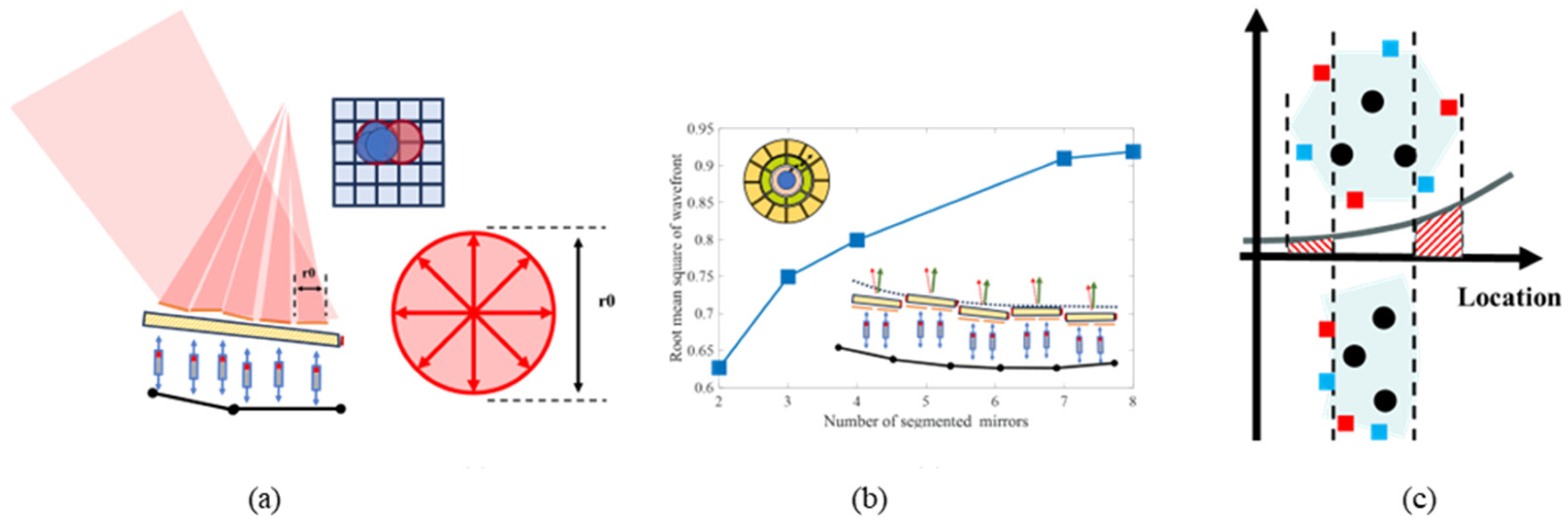
Figure 1 illustrates the overall optimization scheme. When determining the size of the mirror, the atmospheric seeing scale needs to be considered. To simplify the complexity of the system, the number of segments should be minimized as much as possible. We optimize the number of segments by introducing a central mirror and adopting the sector segmentation scheme to reduce the effective scale in the azimuthal direction. This scheme can ensure that the final effective range is closer to the atmospheric coherence length.
Figure 1.
Structure of the operational concept and the principle of coherence matching. (a) The main diagram shows the converging beam being divided into separate paths by the segmentally arranged mirror assembly and directed to the focal point. The blue circle represents the aperture of an individual mirror segment and the red circle represents the diffraction-limited spot formed by a single atmospheric coherent unit (with a diameter of r0). (b) Theoretical simulation of the effectiveness of the system. The diagram is derived from the normal distribution model and root mean square (RMS) error calculation. The telescope’s adjustment accuracy shows an approximate dependency on the segment count. This figure is derived by using a normal distribution of segments and calculating the root mean square (RMS) error. (c) Schematic diagram of the actuator and edge sensor. Each mirror segment is supported by 3 actuators (black dots). The sensor configuration (red/blue squares) varies by geometry: hexagonal segments utilize 6 edge sensors, while sectoral segments utilize 4 edge sensors, enabling the establishment of the global feedback network.
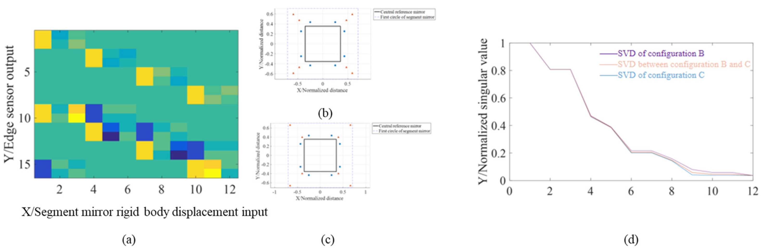
The system achieves coarse co-phasing through wavefront sensing, and uses edge sensors to maintain its stability. Figure 2 shows the measurement points and Singular Value Decomposition (SVD) results.
Figure 2.
Sensor measurement positions and SVD decomposition results: (a) Transfer matrix input − output relationship; (b,c) Impact of two sensor layout distributions on the measurements; (d) System SVD results, indicating robustness of the control matrix. The research establishes that tilt measurement precision always improves with proximity of sensors to edges but is restricted by sensor dimensions. Additionally, systems with fewer segments of the mirror have a more stable control matrix.
The method of SVD involves decomposing the system control matrix into a set of orthogonal ‘correction mode’ and their corresponding singular values to characterize the specific performance of the system. During this process, the singular values obtained through the decomposition can quantify the degree of the system’s response to each mode, and can be interpreted as the error amplification factor under that specific correction mode.
According to Figure 2, the system is less sensitive to low-order error in the point distribution and is negligible. Even under high-order influences, the system’s impact is contained within 10 %. Therefore, it can be considered that the keystone architecture edge sensors are less affected by the installation environment and has obvious advantages in resisting environmental interference.
We first analyze the grating effect of the large-aperture segmented mirror. The grating equation is expressed as
where is the grating constant corresponding to the width of each ruling line, is the diffraction angle, and is the diffraction order set as in this study.
Despite the coarse alignment of the central mirror, significant tilt errors still frequently occur between the segmented mirrors. To solve this problem, we used a pre-liminary alignment method using machine vision technique to adjust the position of the segments.
For large segmented mirrors, assuming that diffraction occurs at the entrance pupil, corresponds to the segment span. In hexagonal segmentation configurations (e.g., adopting the Thirty Meter Telescope standard dimension with for the hexagonal envelope), the system’s performance is evaluated at an operational wavelength of , yielding an angular resolution of . Due to the annular segmentation architecture’s circular symmetry, it can inherently eliminate segment-induced dispersion, avoiding periodic structures in any single orientation.
Machine-vision-based alignment techniques are used during the measurement process. After the light spot detection, the sub-aperture systems perform co-phasing test and adjust the segment edges through focal spot coincidence verification and dispersed fringe analysis. For the relay planar mirrors in the optical path of the telescope, the system low-order aberrations must be actively compensated. This can be achieved through curvature-sensing-based wavefront measurement and control systems.
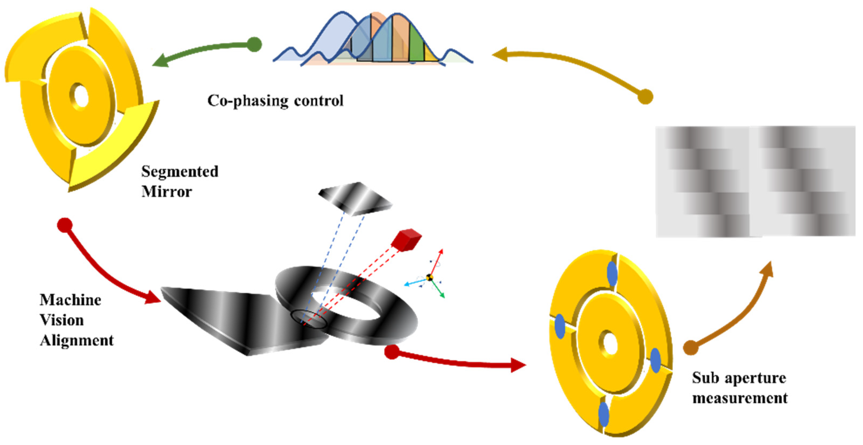
The whole work flow of the alignment is illustrated by Figure 3. It achieves large-aperture stitching through annularly arranged keystone segments. The key advantages include that it possesses uniform segment geometry to ease manufacturing, rotational symmetry to enhance thermal stability, continuous spatial frequency coverage to prevent imaging information loss, and compatibility with low-order aberration in coaxial optical systems. Annular form also prevents diffraction spikes related to conventional designs.
Figure 3.
Work flow of the hybrid alignment strategy for segmented mirror. (1) Coarse co-focus and co-phasing alignment, (2) Machine vision alignment, (3) High-precision interferometric testing, (4) Result verification. The arrows indicate the flow of the control process, and the illustrations depict the corresponding physical states of the mirror system.
2.2. Optical Performance Simulation Based on Optical Transfer Function
To evaluate the optical quality, we analyzed the segmented mirror’s impact on the performance of a large imaging system. In this simulation, the segmented mirror was placed in an ideal aberration-free optical system. Then we calculated the overall OTF to quantify image degradation from surface errors. As can be seen from Fourier optics, under non-co-focused(defocused) conditions, the system’s OTF will be severely attenuated at high spatial frequencies causing the system to act as a strong low-pass filter [22]. Consequently, only near-zero-frequency signals can be carried by the system and give superimposed images of multiple targets.
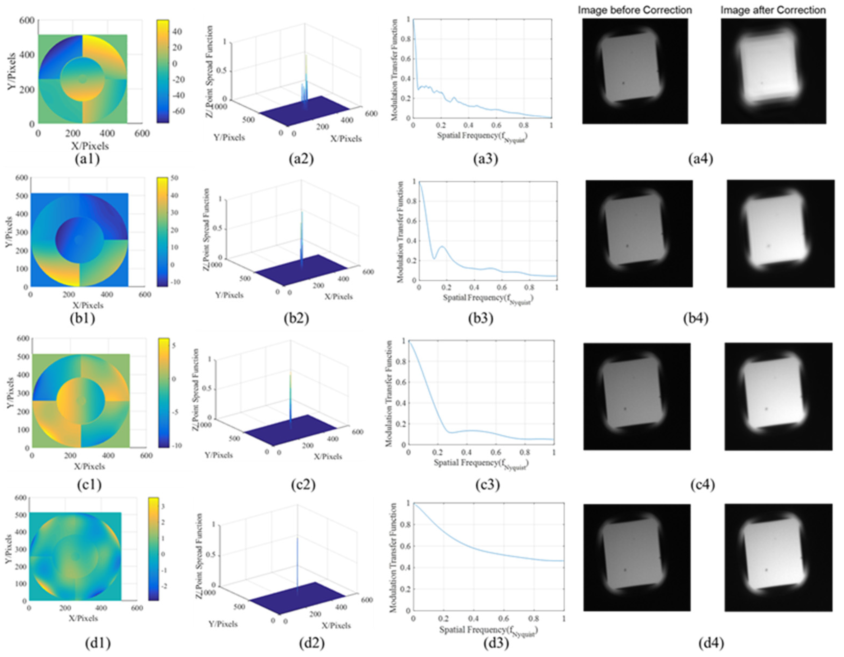
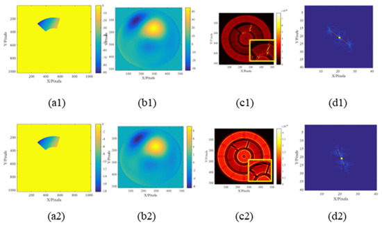
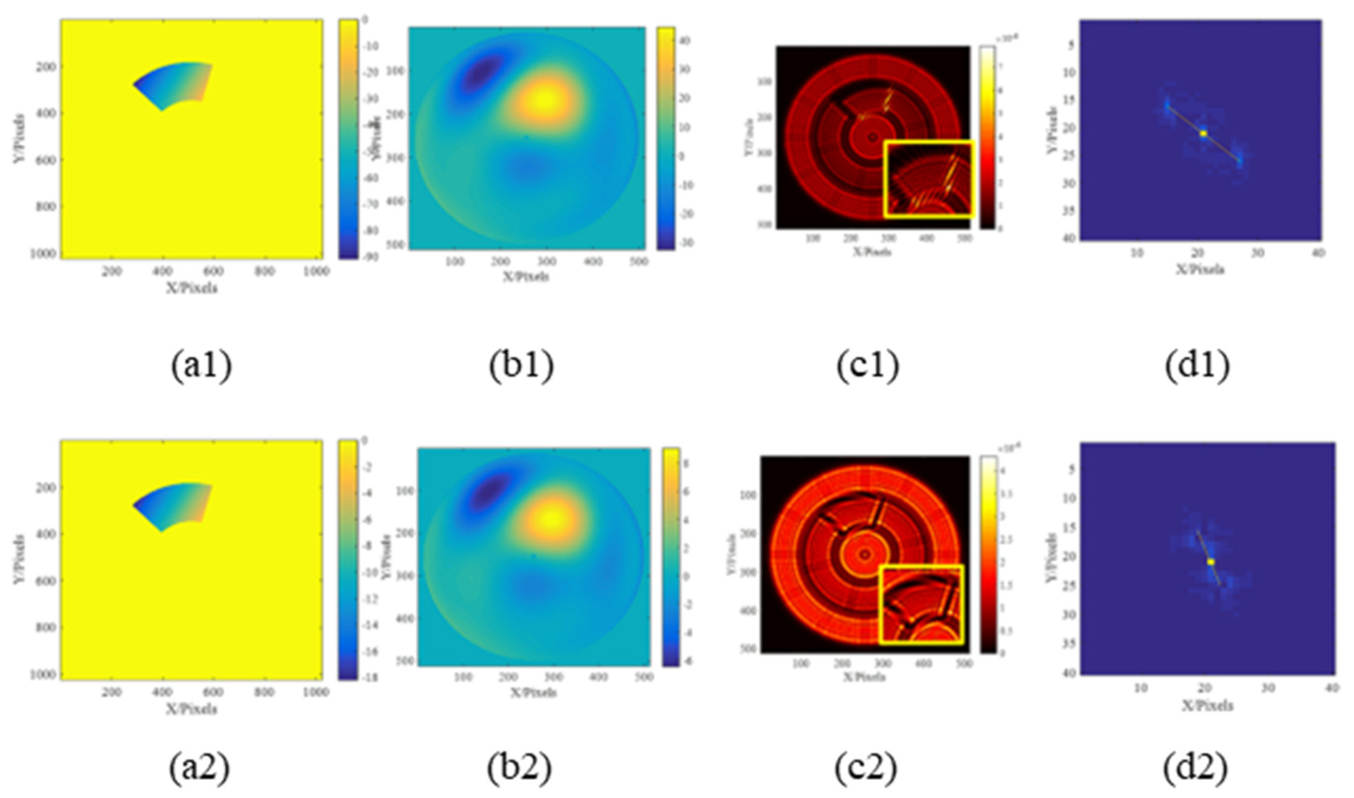
The simulation results for the segmented mirror within an ideal imaging system demonstrate the correction process. In the initial co-focus alignment process, the tip/tilt of each sub-mirror is adjusted to achieve coaxial alignment, enabling each focal spot to overlap precisely. After that, because of the random piston error between the segmented mirrors and the influence of interference, a speckle pattern will appear on the focal plane. The range of the speckle pattern is determined by the diffraction limit of the segment mirrors. In the following co-phasing state, the segment mirrors will gradually achieve co-phasing and the energy within the speckle pattern constructively interferes and coalesces, which makes the system’s PSF to converge to the theoretical diffraction limit of the complete annular aperture. During the co-phasing state, wavelength-scale compensation is achieved through precise adjustment and the low-order wavefront sensing requirements are met. The effectiveness of the system’s regulation and the accuracy of the control system are verified by observing the reduction of the PV value through input adjustment. Figure 4 shows the performance parameters of four working states of non-co-focused, focused, co-phased and post-low-order aberration compensation.
Figure 4.
Simulated performance of an ideal imaging system incorporating the segmented mirror in four states: (a) non- co-focused, (b) co-focused, (c) co-phased, and (d) post-low-order aberration compensation. Each row includes the residual wavefront error map (a1−a4), the resulting system points spread function (b1−b4), the system modulation transfer function (c1−c4), and the system’s pre-/post-correction imaging comparison (d1−d4).
3. Principles of Integrated Detection and Control
3.1. Coarse Alignment Principle Based on Machine Vision
Due to the limited capture range of fine-stage sensors and the necessity for operation under varying illumination conditions, a machine vision system is employed to facilitate coarse alignment. By observing the reflection of a known calibration board in the planar mirror through measurement cameras and analyzing the captured reflected image, the precise pose of the mirror can be calculated. Due to the high real-time performance of machine vision, the alignment process is significantly optimized.
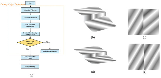
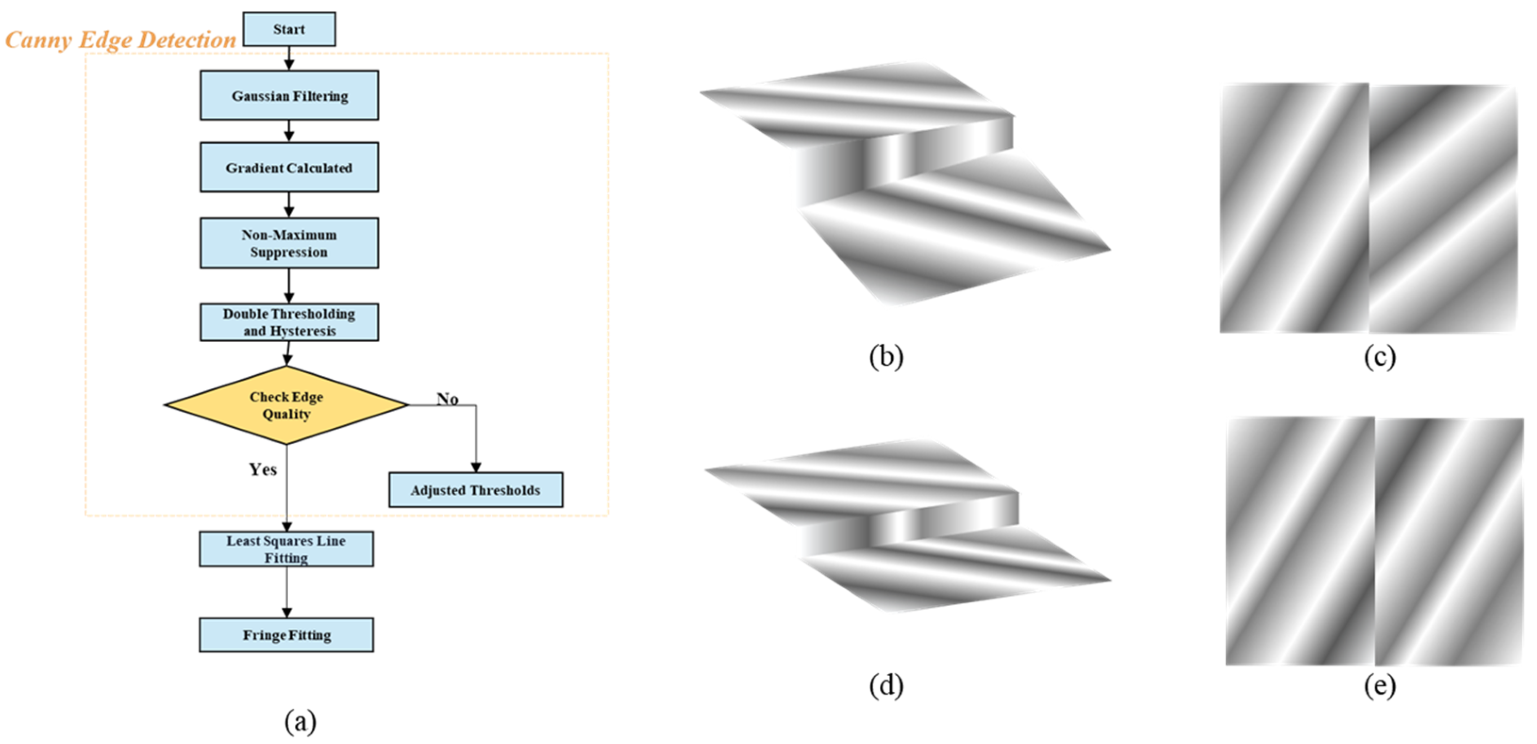
To meet high-performance corner detection, particularly for extracting the precise orientation of sub-mirrors, two requirements must be fulfilled: high-fidelity edge detection, and mathematical line fitting to the detected edge points. Accordingly, we adopt a robust two-stage approach. Due to the performance of Canny operator in suppressing noise and localization accuracy, it is used for the initial stage [23]. As for the line fitting, the least squares method is employed to transform the discrete edge pixels into precise linear equations.
The workflow of the machine vision detection is shown in Figure 5. Once high-quality discrete edge pixels are obtained, least squares line Fitting is employed to fit the pixel sets to a linear model (), yielding the optimal slope and intercept for each boundary line.
Figure 5.
Flowchart of the edge detection algorithm and schematic of fringe alignment. (a) Detailed flowchart of the improved Canny-based edge detection and Least Squares Line Fitting algorithm. (b,c) The correction process for relative tilt errors between segments, where the parallelism of the interference fringes is achieved by adjusting edge gradients. (d,e) The transition from the initial misaligned state to the co-focus and coarse co-phasing states.
After establishing the linear model for each boundary line, we focus on the relative posture between adjacent segments. Specifically, the slopes of the fringe center-lines for the adjacent left and right are calculated and denoted as and . In physical optics, the parallelism of the dispersed fringes directly shows the relative tilt between the segments. Therefore, the difference of slopes is adopted as the primary alignment criterion
Here, represents the tolerance threshold. When this condition is met, the segmented mirrors are considered to have achieved the desired coarse alignment state.
The quantitative values derived from this line extraction process provide the foundational data for subsequent analysis. Because of the complex intensity distribution of ambient light (e.g., sunlight) in real scenes, research on target feature extraction methods under natural illumination is necessary. Thus, adjustment and alignment re-fer to establishing a mapping correlation between the optical coordinate system and the mirror support actuator mechanism and following later adjustments in the optical aberration-driven actuators. Unlike conventional computer-aided alignment involving inversion of wavefront aberration influence matrix to achieve adjustment vectors, segmented mirror vision-assisted alignment has a wider dynamic range and greater nonlinearities in the system.
The segmented optical system is composed of multiple independent sub-mirrors combined through precise adjustment mechanisms. Its imaging performance mainly depends on the co-focus and co-phasal accuracy of each sub-mirror. The position and pose errors of the sub-mirrors can be decomposed into translational and tilting errors ().
We use machine vision for the alignment detection of large-diameter segmented mirrors. The principle lies in mapping between continuous spatial coordinates and discrete coordinates. In a spatially segmented system, the continuous stripes correspond to a modulus operation, while the scale during the modulus operation represents the diameter stitching span. This clarifies the decoupling of tilt information in the non-discrete domain and the high-precision extraction mechanism of system corner points and lines under non-uniform illumination conditions, as well as the non-continuous, serrated multi-pixel smoothing mechanism at the edges and the blurring effect of detector noise on corner point positions. Here, the accuracy of line extraction under mirror machine vision is enhanced by the use of erosion and the regulation of the system’s connected domains. Ultimately, pixel-level image alignment was achieved, and spot verification was conducted using a focal-plane camera with an accuracy better than 10 arc seconds. In practical use, after the initial calibration, the system can quickly restore the alignment state through machine vision after replacing sub-mirrors and relocation. As shown in the formula,
The phase distortion caused by the tilting and translation of sub-mirror i is
where is the ideal optical pupil function of the mirror (typically a rectangular or circular function), is the phase distortion caused by the tilting and translation of mirror , is the modulus operation symbol, are moduli for x- and y-direction modulus operation, respectively, is the polar radius in polar coordinates, and is the polar angle in polar coordinates.
3.2. Co-Phasing Measurements Based on Dispersion Fringes
In order to achieve the continuity of the mirror surface, co-phasing measurements are indispensable. The approach uses patterns that show specific features at the joining location. By analyzing the seam using dispersed fringes, the local-precision phase measurement can be obtained.
According to the grating equation using a grating with 300 lines per mm (d = 1 mm/300 = 3.3 μm), the derivative of both sides of the grating equation provides the following expression:
From the formula transformation, we obtain
Considering the incident wavelength with a width of 200 nm, the angular broadening is .
The phase distortion is reflected in the system transfer function through the coherent superposition of the optical pupil function, resulting in the loss of high-frequency information and reduced contrast. The system optical pupil function, , is the superposition of the optical pupils of each constituent mirror, expressed as
For the local area of the segmented mirror, the narrowband method solves the focal plane light field as the Fourier transform of the pupil function:
where is the coordinate of the light field distribution, is the polar angle in polar coordinates, is the piston error, is the diameter of the segment aperture, is the wavenumber, () are the polar coordinates corresponding to the sub-aperture in the pupil plane, and is the Fourier transform.
The light intensity distribution is given by
where is the light intensity distribution at a single wavelength. Consequently,
When , that is, when approaching the common phase, we obtain
The visible localized intensity difference can converge consistently with the piston error.
3.3. Global Control of Wavefront Stability
3.3.1. Construction of the Control Matrix
To enhance co-phasing stability and reach nanoscale precision, we established a global feedback control mode to link the segment actuators with the readings of the edge sensors. The mathematical relationship between the actuators and sensors is defined using matrix formalism similar to the matrix of Keck and TMT.
For each fan-shaped mirror surface, its back is supported by three actuators. Let the vector
(m = 1, 2, 3) represent the displacement of the MTH actuator. The surface plane of this block is uniquely determined by these three points. For any point on the surface of the block, its vertical displacement can be expressed as a linear combination of actuator displacements.
where represents the geometric influence coefficient determined by the actuator coordinates relative to the mirror center.
While the edge sensor primarily detects the piston error which along the optical axis, the coupling effect of relative tilts between adjacent segments allows the sensor to capture tilt information. This multi-degree-freedom sensing capability provides a more robust feedback mechanism for maintaining the co-phasing state of the system.
For an edge sensor located at the interface between segment and segment , the sensor reading is defined as the difference in edge height between segment and segment at that location.
Here, the partial derivative represents the sensitivity coefficient, corresponding to the element in the control matrix. This coefficient depends on the radial distance from the sensor to the segment center and the geometry of the actuator triangle.
When this local relationship is extended to the entire array, the system satisfies the principle of linear superposition. For a system consisting of blocks and a total of M actuators (), the global control matrix is assembled by collecting these sensitivity coefficients. The total change vector of the sensor reading is the matrix product of matrix and the actuator displacement vector .
Matrix is a sparse matrix because the reading of each sensor is only affected by the six actuators belonging to the pair of blocks it is connected to. However, the connectivity of the blocks (especially the ring structure connecting block N and block 1) ensures that matrix couples all the blocks into a unified stiffness matrix, thereby allowing for the solution of the global wavefront mode.
The difference between the measurement and calibration vectors is denoted as . The least-squares loss function, given by , is solved using the damped least-squares method.
3.3.2. Maintenance of Wavefront Stability
For wavefront correction using edge-sensing-based control, hybrid control with a combination of zonal and modal approaches is widely used. The stepwise recursive method is utilized in the zonal approach to correct tip/tilt and piston aberrations sequentially from center to periphery for neighboring mirrors, and it can be used for localized compensation of high-order aberrations. The modal method reconstructs the full wavefront by global fitting (e.g., Zernike polynomial expansion) from the phase data of all the measurement points, with superior low-order aberration correction such as defocus, astigmatism, coma, and field curvature [24,25]. In practice, low-order aberration terms are rapidly controlled by projection onto basis modes, and residual high-order errors are slowly damped by the zonal method.
In practical applications, low-order aberration components are adjusted by projecting onto basis modes, while residual high-order errors are progressively suppressed through the zonal approach. The synergy of the techniques is achieved through the blending of their respective Jacobian matrices. The Jacobian matrix of the low-order mode is combined with the zonal method and then solved uniformly in singular value decomposition (SVD). This maximizes low-order aberration correction while maintaining high-frequency error control at a high level of precision. The hybrid technique maximizes both computation efficiency and error correction, which makes it amenable to active wavefront control for large-aperture segmented optics.
The objective of the active control system is to determine the required actuator correction amounts to eliminate the measured sensor errors . This requires inverting matrix . However, since edge sensors are blind to global rigid body modes (e.g., global piston and tip/tilt), matrix is typically singular. We employ Singular Value Decomposition (SVD) to calculate the pseudo-inverse. Matrix is decomposed into
where and are the orthogonal arrays that define the sensor mode and the actuator mode, respectively, is the diagonal array containing singular values , and the reconstruction matrix B is
Noise propagation from sensor to actuator serves as a key indicator of system robustness. Following the error analysis method used in Keck/TMT, we introduce the noise multi-plier . Assuming that the sensor noise follows a Gaussian distribution, the relationship between the RMS error and the sensor noise is , where the global noise coefficient is determined by the system singular values:
Here, represents the non-zero singular values. A lower indicates that the control system possesses higher rigidity and robustness.
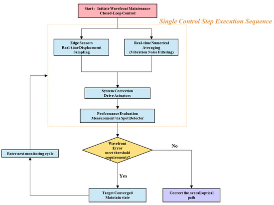
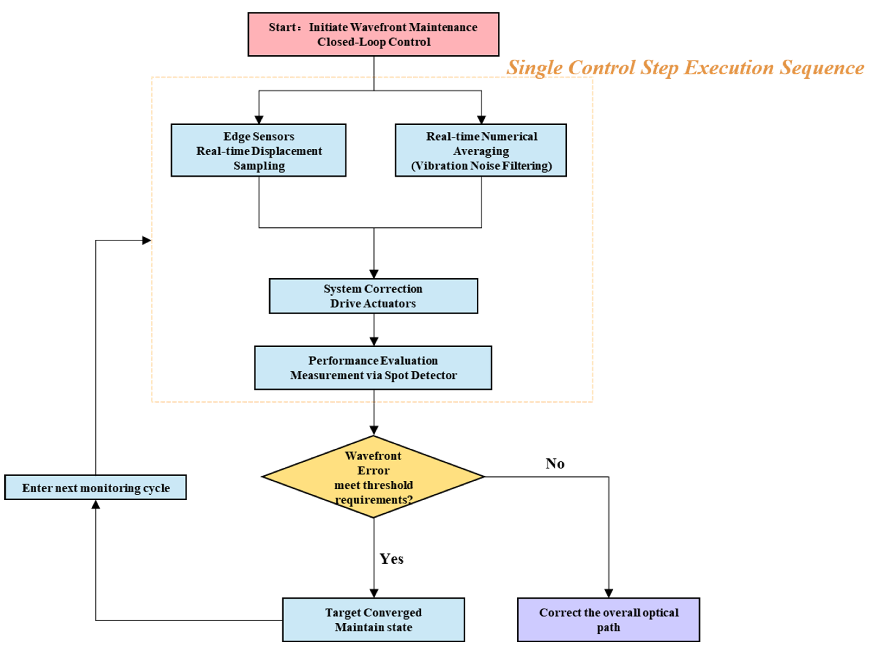
For the keystone architecture, owing to its annular closure constraints and rotational symmetry, the singular values are well-conditioned, thereby allowing the system to maintain at a low level. From the above theoretical analysis, we can conclude that during the mirror reconstruction process, the measurement noise generated by the edge sensor will not be amplified overly. The specific execution sequence of the closed-loop feedback control is illustrated in Figure 6.
Figure 6.
Flowchart of the closed-loop feedback correction process.
Error accumulation is a critical issue in segmented systems. In a dual-mirror system, if the height difference between adjacent segments is 20 nm and the radial direction contains 10 rings, the overall amplitude of the low-order control can reach 200 nm. Accordingly, the relation for the low-order control amplitude can be expressed as
where is the amplitude of low-order control, is the number of (radial or azimuthal) segment boundaries along the error propagation path, and is the step height difference between adjacent segments.
In the process of designing a large-aperture planar mirror, error distribution has an intimate connection with bandwidth, spatial frequency, and the telescope scale.
Different bandwidths and spatial frequencies correspond to different scale requirements of the telescope. In the accurate fabrication of a large-aperture planar mirror, its time and spatial frequencies of regulation should be adjusted reasonably according to the scale of the target. Therefore, the error allocation can be optimized to ensure the quality of the mirror surface and to observe performance.
3.4. Low-Order Aberration Correction Principle Based on Curvature Sensing
To correct the low-order surface figure errors in the segmented mirror system, the modal approach is primarily adopted. Specifically, the surface irregularities derived are represented as vectors orthogonal to the pupil plane for wavefront control in the phase difference space. To handle annular mirror characteristics, we utilize Zernike polynomials for constructing an orthogonal basis. The Zernike basis functions are formulated from different azimuthal and radial symmetries so that low-order aberrations can be precisely correctable.
In large segmented mirror systems, low-order aberrations can be compensated through primary mirror adjustments. Consequently, the wavefront detection must satisfy requirements for both large dynamic range and high precision in the final stage. Curvature sensing has wide dynamic range characteristics and enables accurate focal-plane-based wavefront sensing. By decoupling the translation errors introduced by the edge sensor’s tilt lever effect on the axial movement of the segment boundaries, and analyzing the correction path of the semi-active components via curvature sensing, the joint modulation mechanism of surface shape and rigid body displacement on the wavefront in the co-phasing region can be clarified. For wavefront reconstruction, the intensity difference is fitted using an orthogonalized curvature basis, after which the Poisson equation is solved over an orthogonalized annular domain.
4. Experimental Validation
4.1. Experimental Setup Overview
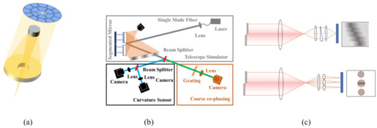
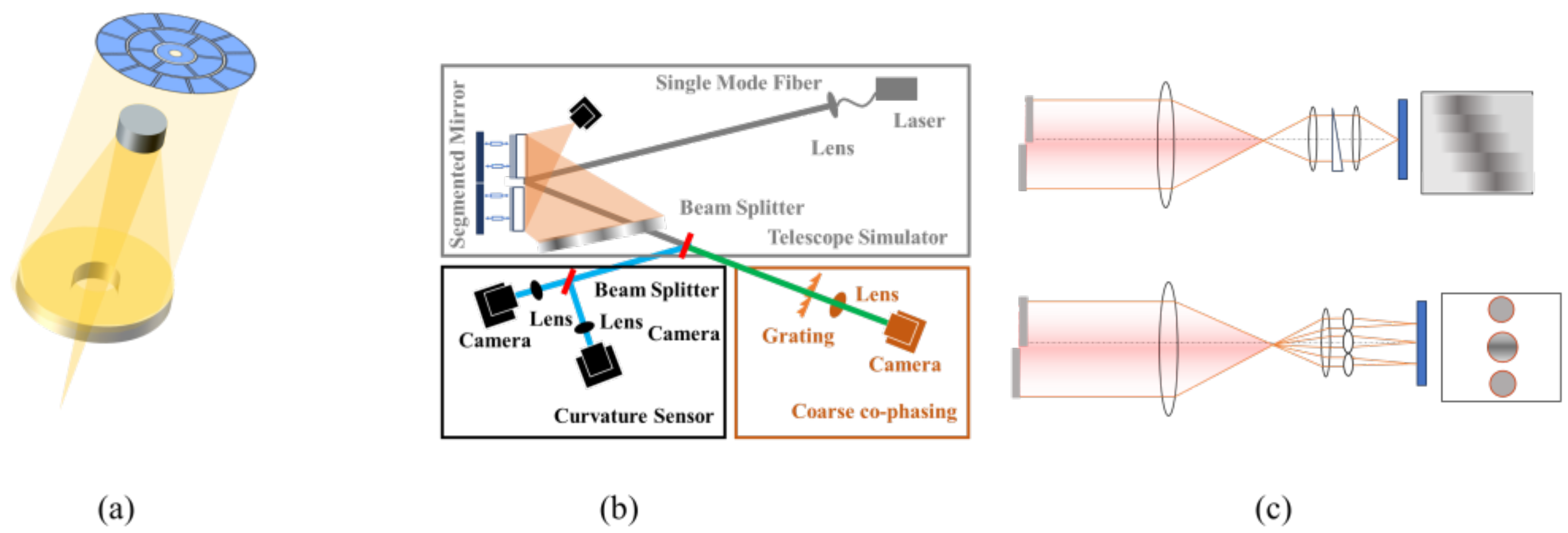
In support of the theoretical approach developed in Section 3, a comprehensive experimental system was built including multiple measurement subsystems for total characterization and control of large-aperture segmented planar mirrors. The schematic of the comprehensive experimental setup is shown in Figure 7. The experimental installation employs coordinated multimodal measurement methods, progressing systematically through machine vision alignment towards co-phasing optimization, stability, and low-order aberration control. Individual testing of each subsystem is provided through modular design while simultaneously demonstrating their synergistic operation in ensuring diffraction-limited performance.
Figure 7.
Multimodal integrated detection system for large-aperture segmented planar mirrors. (a) 3D schematic of the keystone segmented mirror assembly, illustrating the specific annular arrangement and the optical beam path. (b) Detailed layout of the experimental optical path integration. The system uses a single-mode fiber laser source and beam splitter to distribute light into 2 sub-branches: the Curvature Sensing Branch (left) with dual-camera setup for wide dynamic range wavefront sensing, and the Co-phasing Detection Branch (right) with dispersed grating system for both coarse and fine co-phasing measurements. Figure (c) depicts the detection principles: the dispersed fringe method and the broadband method.
4.2. Validation of Machine-Vision-Based Alignment
To validate the coarse alignment principle described in Section 3.1, the machine vision system was implemented using a checkerboard calibration board and a camera in front of a segment mirror.
The Canny edge detector was used to process the captured images and extract the contour of the calibration edges. By analyzing the geometric properties of these edges, tilt and positional deviation can be quantified. For a system with a large number of mirror segments requiring long-term observation, similar machine vision technologies can be applied to periodic phase calibration and system health monitoring.
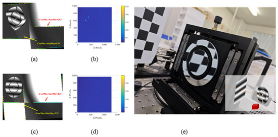
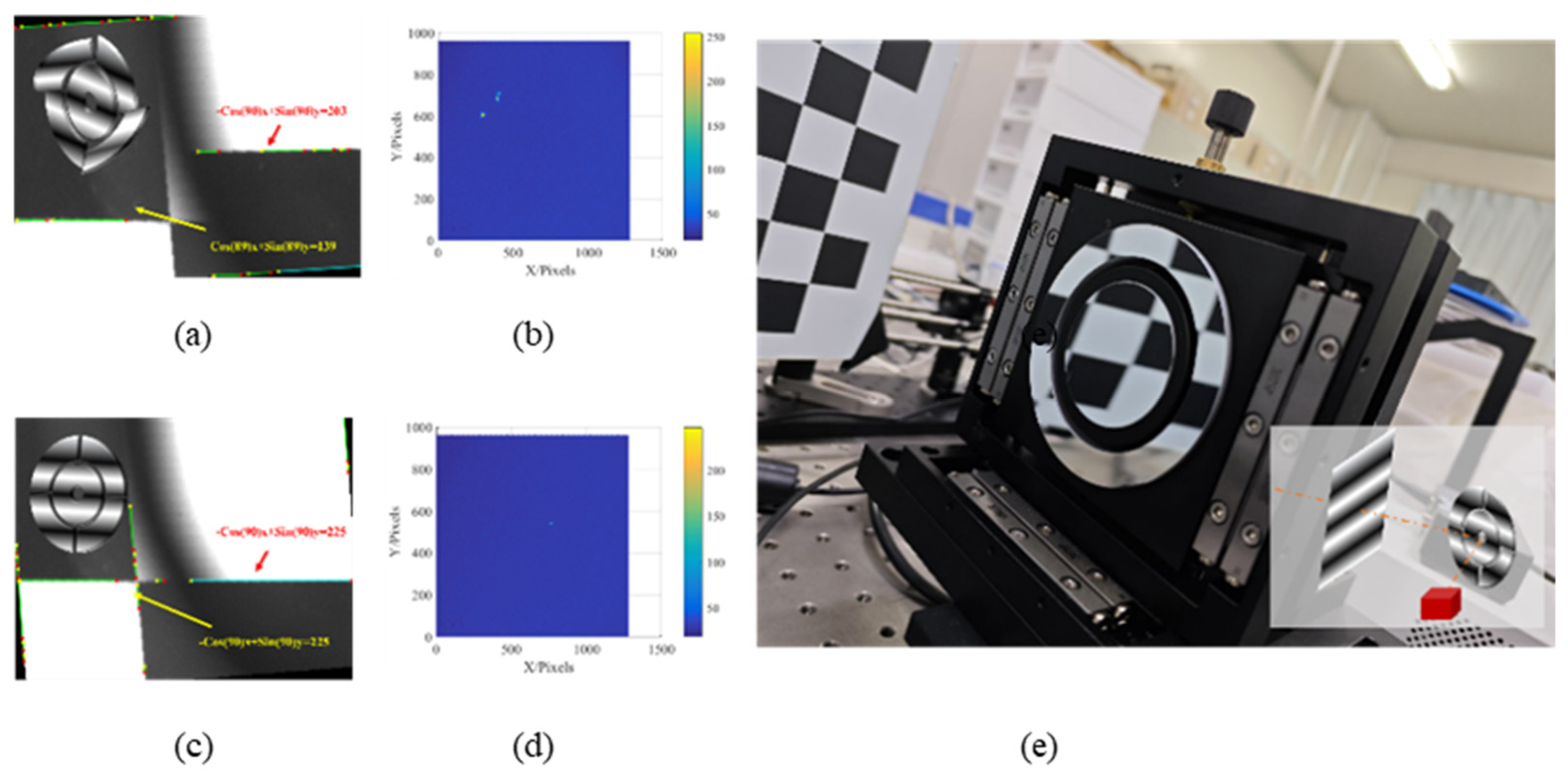
The implemented machine vision system achieved alignment of segmented mirrors through iteration measurement with focal spot images, achieving an alignment accuracy below 10 arcseconds. After adjustment by machine vision, precise convergence and integration of the detected image points enable robust coarse alignment at the pixel level co-focused detection. The optimized machine vision results are shown in Figure 8.
Figure 8.
Experimental results of the segmented mirror alignment system using machine vision system. (a) Misaligned state showing detected target features by cross-correlation analysis, (b) corresponding spatial frequency domain image, (c) aligned state following machine vision alignment with improved feature registration, (d) final spatial frequency response demonstrating improved alignment accuracy, and (e) experimental setup showing the calibration target, machine vision system, and segmented mirror assembly. By using wide spectral response and real-time capabilities, combined with an alignment camera, the machine vision system can achieve precise alignment of multi-level components. The core principle of the system based on the mapping between continuous spatial coordinates and discrete coordinates. Robust sub-mirror attitude extraction is achieved through high-fidelity edge detection and mathematical line fitting. This method ensures the precise alignment of large-aperture mirrors. The system uses iterative visual feedback control to achieve an alignment precision of less than 10 arcseconds This approach covers a large dynamic range, reducing initial degree-order errors to arcsecond-order accuracy.
4.3. Co-Phasing Test Based on Dispersed Fringes and the Narrowband Method
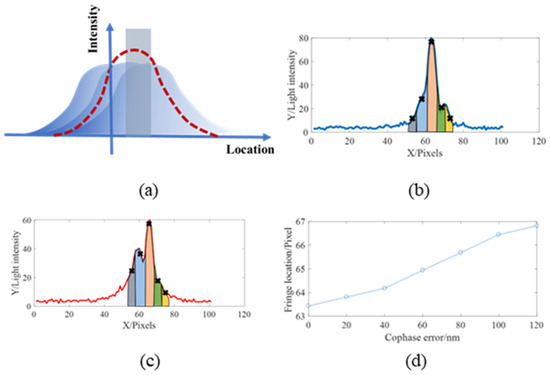
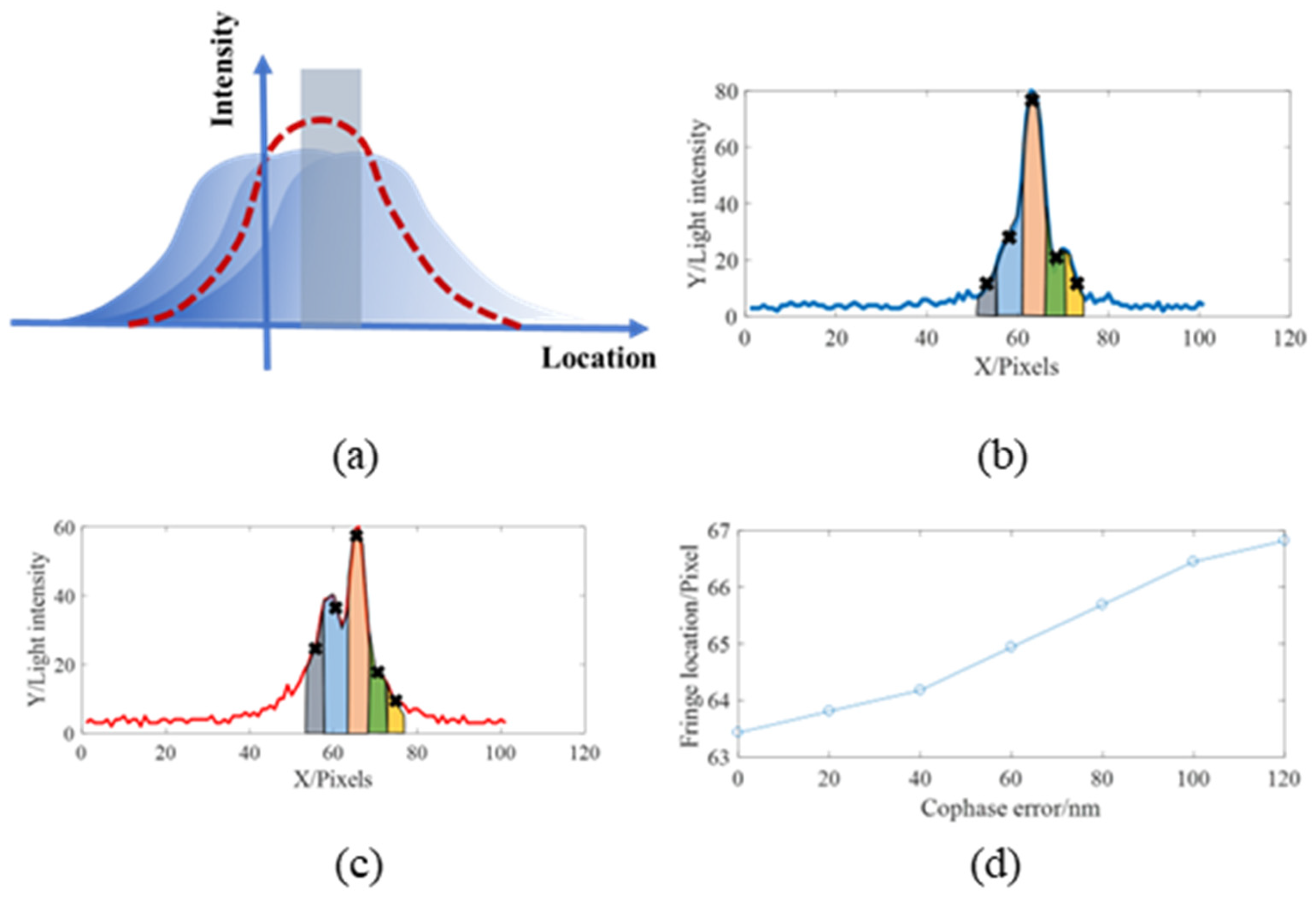
During the co-phasing stage, a dispersed fringe combined with the narrowband method was employed to achieve co-phasing adjustment, enabling large-scale and high-precision co-phasing measurements and accurate control of the segmented mirrors. Specifically, a dispersed fringe was first used for coarse co-phasing [26]. Consequently, the Fourier transform of interference patterns and the extraction of secondary frequency-domain peaks with center convergence control adjusted the piston error between two paths to within one wavelength. Subsequently, phase scanning and fitting were performed at the central wavelength position of the dispersed fringe. Precise co-phasing used the correlation with the diffraction-limited Bessel function. This method achieved a measurement accuracy better than 30 nm, which also avoided errors from fluctuations in single-point intensity calculations. Figure 9 shows the large-scale and high-precision co-phasing measurements. These results rely on the dispersed fringe and narrowband methods.
Figure 9.
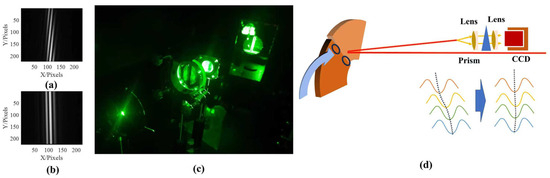
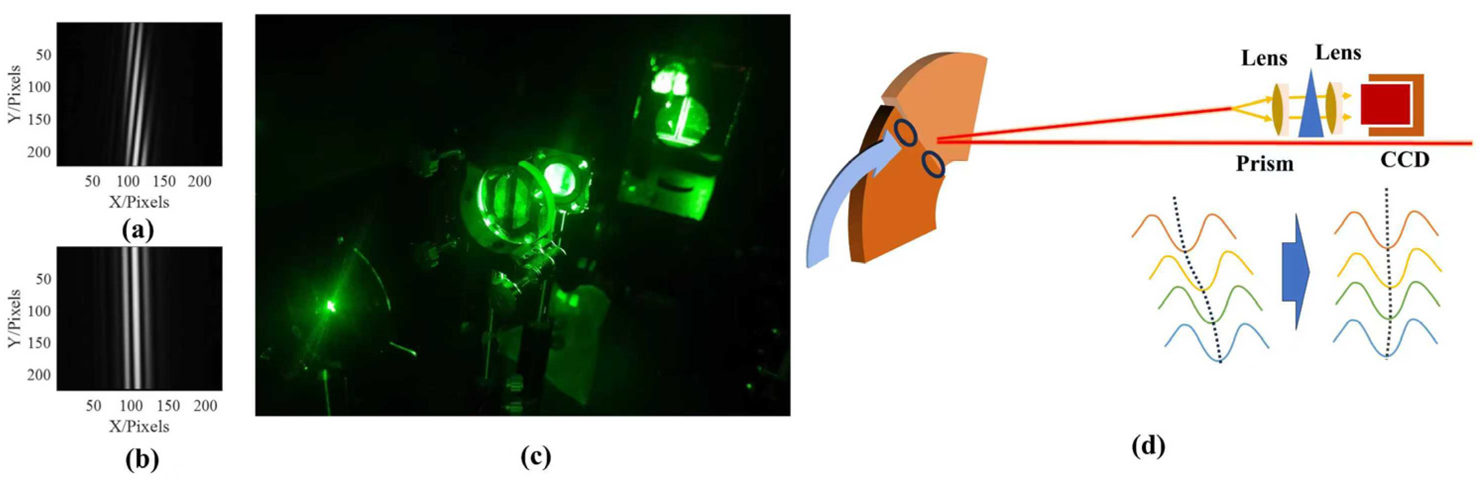
Co-phasing measurement with the dispersed fringe method. (a) Dispersed fringe pattern generated by the broadband source before coarse co-phasing showing numerous orders of interference and phase discontinuities, (b) dispersed fringe pattern after coarse co-phasing with smaller phase errors and improved fringe contrast, (c) experimental setup showing dispersed fringe detection system and under-test segmented mirror, and (d) schematic diagram of the beam combination and detection system showing segmented mirror, prism disperser, lens, and CCD detector. Notably, the detection system uses a sub-aperture approach, where it is aligned to collect light only from the boundary region of two adjacent segments. The reflected beams from this local area are then combined by shared optics (lens and prism) to create an interference pattern on the CCD detector. After adjustment, the interference peak is manipulated from a curved state into a straight vertical pattern across the spectral bands. This transformation confirms the elimination of phase errors, indicating that the segments are successfully co-phased.
Figure 9 shows the large-scale coarse co-phasing measurements based on the dispersed fringe method. Subsequently, precise co-phasing with an accuracy better than 30 nm was achieved by utilizing the correlation with the diffraction-limited Bessel function (Narrowband method). Figure 10 shows the high-precision fine co-phasing measurements. These results rely on the dispersed fringe and narrowband method.
Figure 10.
Fine co-phasing measurement via correlation-based phase optimization. (a) Schematic of the peak extraction principle; the red dashed line represents the intensity envelope and the shaded area indicates the light spot; (b) multi-wavelength interference pattern with spectral dispersion over detector; (c) phase scanning and correlation analysis with theoretical diffraction-limited Bessel function to find optimal phase position, where the intervals between data points represent the translation step size; and (d) ultimate step-height accuracy verification with nanometer-scale precision. By utilizing the maximum correlation point between calculated and measured patterns, this approach achieves a co-phasing accuracy improvement of over 30 nm compared to methods that do not eliminate single-point intensity fluctuation errors. This method allows for precise co-phasing of a high-quality following the initial coarse alignment with scattered fringe analysis.
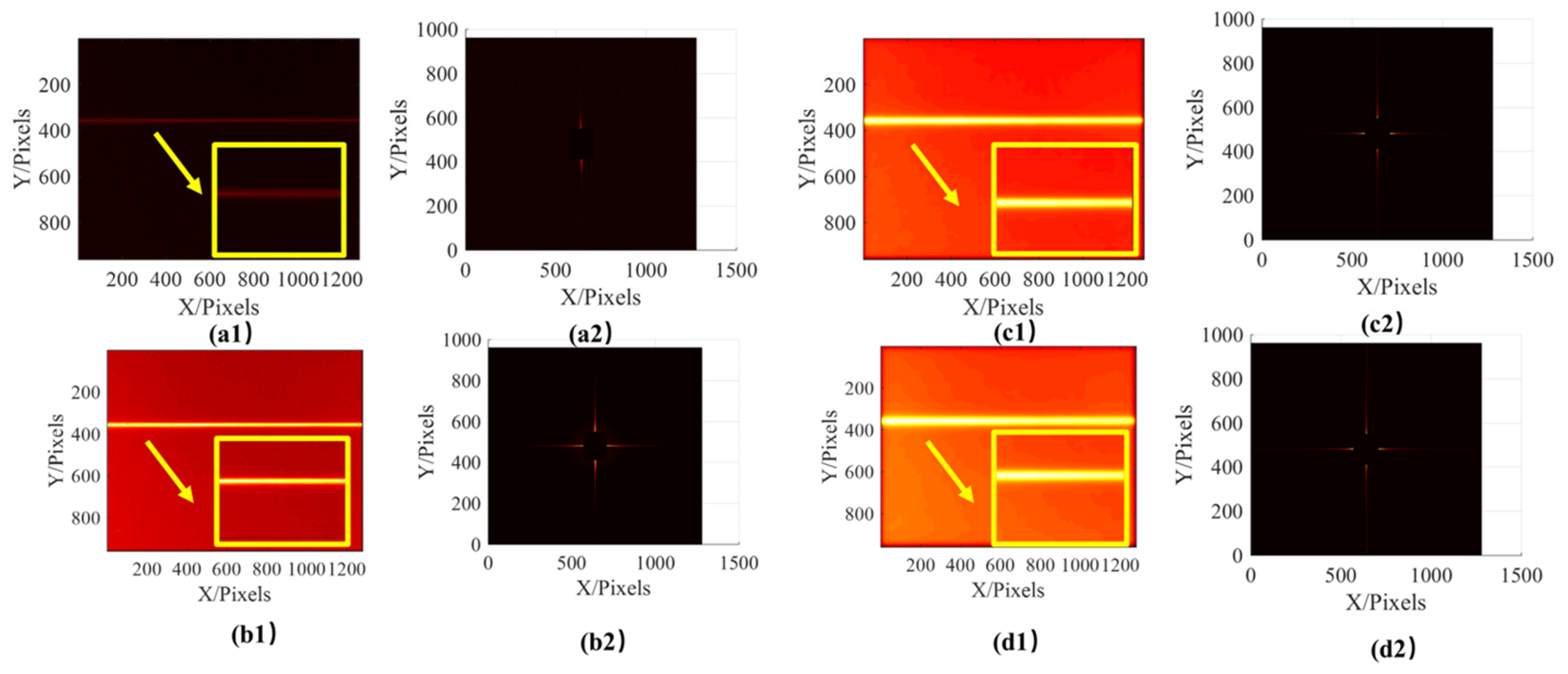
Considering the various disturbances at the observation, the robustness of this technique against disturbances must be considered. For co-phasing correction, this study conducted error analyses on the extraction capabilities of dispersed fringe and broadband measurements, respectively, while simultaneously considering the effects of both mirror seeing and fine pointing jitter of sub-mirrors. The disturbances to the dispersed fringes under different equivalent blur levels are shown in Figure 11. According to Figure 11, when the cumulative magnitude of external comprehensive influences exceeds 1.45, the dispersed fringes become significantly blurred, making it impossible to extract relevant information effectively. Therefore, to ensure system stability and data reliability, stringent constraints have been imposed on both atmospheric effects and the amplitude of the system’s tracking pointing jitter.
Figure 11.
Effect of equivalent blur on dispersed fringe patterns. (a1,a2) Dispersion fringes and frequency domain measurement results without disturbance; (b1,b2) dispersed fringe and frequency domain measurement results under 0.3″ disturbance; (c1,c2) dispersed fringe and frequency domain measurement results under 1″ disturbance, and (d1,d2) dispersed fringe and frequency domain measurement results under 1.45″ disturbance.
4.4. Stability of Keystone Architecture
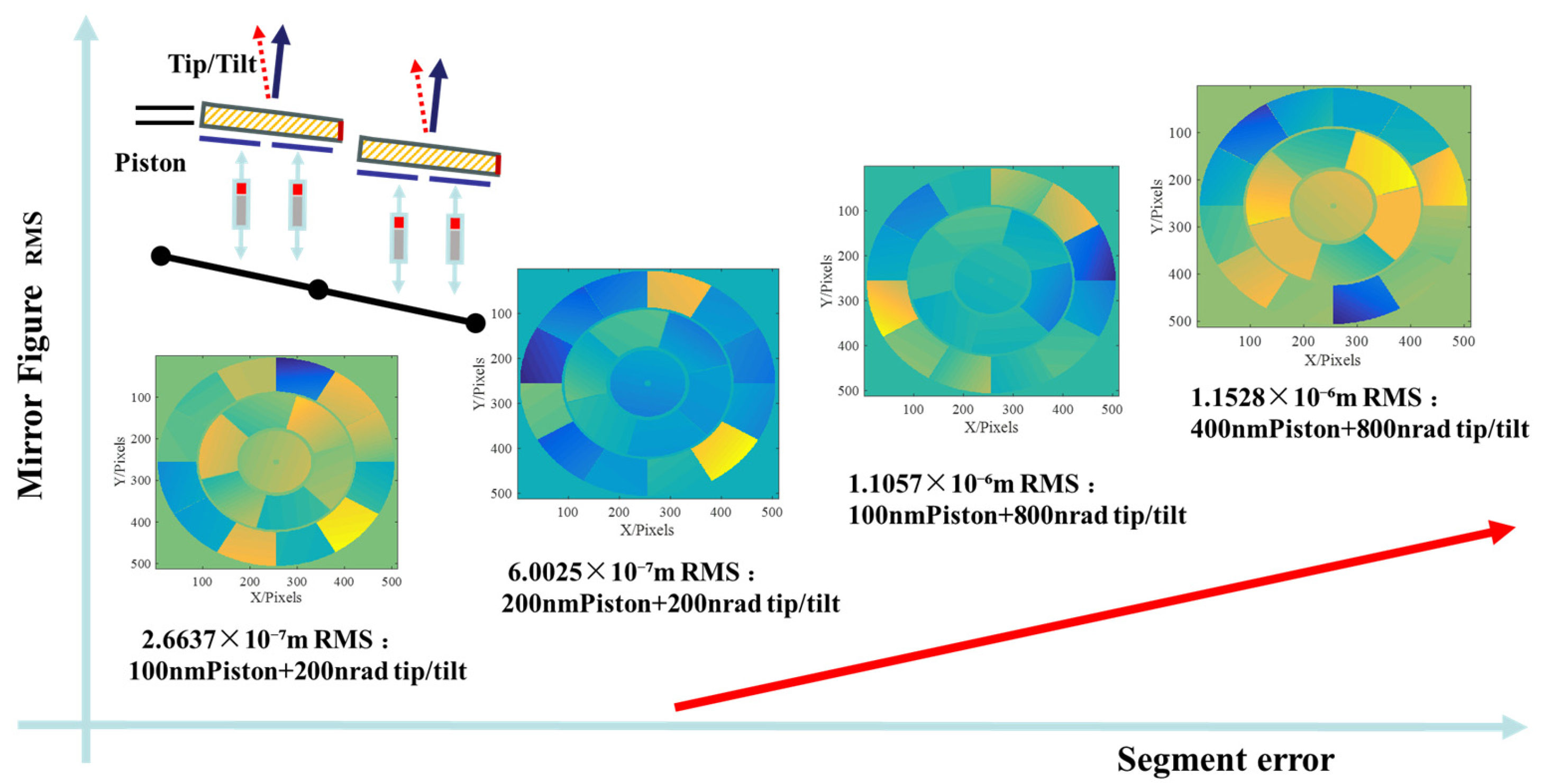
The accuracy analysis of the edge sensor was conducted, and the results are shown in Figure 12. According to Figure 12, the statistical propagation relationship between the intrinsic errors of different mirror segments and the overall system RMS error can be obtained. The analysis shows a linear correlation between the tip/tilt errors and surface figure errors (e.g., PV error) of individual mirror segments and the overall system RMS error. This indicates that the overall system performance can be predicted and managed by controlling these critical error parameters of individual mirror segments. By analyzing Figure 12, the quantitative basis for optimizing system design and error budgeting can be established.
Figure 12.
Accuracy analysis results of the edge sensor. The figure displays the aberration distribution maps as four different magnitudes of wavefront aberrations (with key values increasing from 266 nm to 1153 nm).
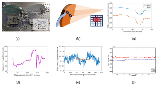
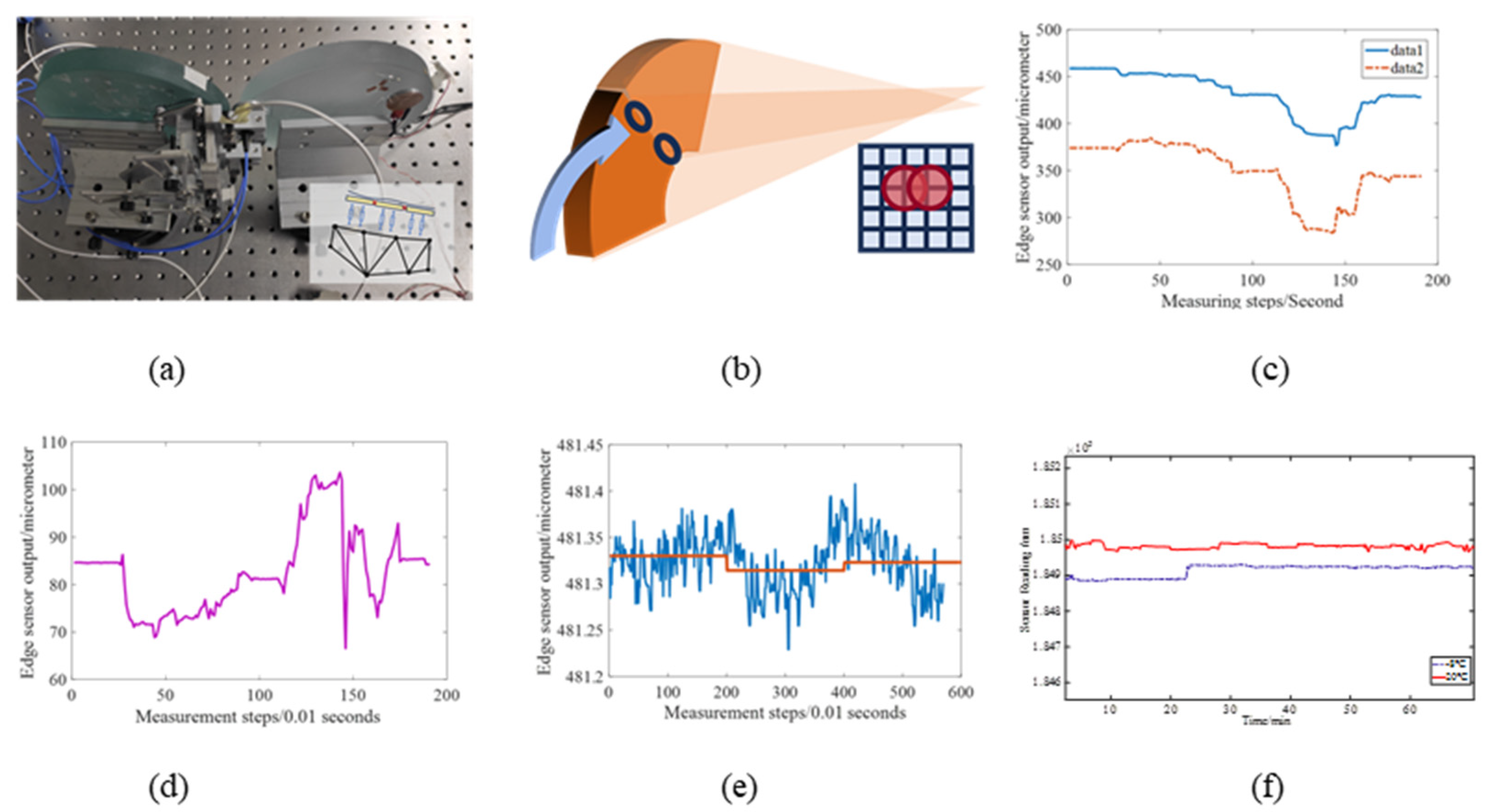
For the equivalent validation of the calibration process for edge sensors during non-image closed-loop operation, a zero-point calibration of edge sensors with an accuracy of 0.4″ was achieved based on the far-field range camera. For the case of horizontal translation of the light spot, the calibration accuracy was better than 0.056″. Furthermore, dynamic characterization confirmed that the resonant peak of the measurement device is above 100 Hz, thereby ensuring compatibility with the measurement and correction frequency of active optics (Figure 13).
Figure 13.
Calibration process and stability analysis of the edge sensor. (a) Experimental device for the calibration process during co-focus operation, (b) principle of calibration, (c) variation of edge sensor values under 0.4″ angular displacement, (d) sensor reading, (e) periodic drift between correction steps, and (f) comparison of edge sensor stability between laboratory (20 °C) and outdoor (−8° C) environments.
In terms of stability, the sensor drift exhibited a PV value of approximately 30 nm at room temperature and 40 nm under outdoor conditions. The mean static error induced by the temperature difference was measured at 70 nm. By combining this thermal error with the 30 nm dispersion error, the total RMS error of the system is calculated to be 76.2 nm.
4.5. Low-Order Aberration Sensing and Control
After the astigmatism control and measurement, the residual tilt is corrected using partitioned fitting of mirror regions to determine wavefront tilt, followed by control and measurement. The RMS convergence of the system wavefront matches the input disturbance. However, the limited number of keystone mirrors causes the boundaries to become large and nonconvex, leading to crosstalk at the edges. In practice, we can filter out such errors by planar fitting over mirror regions.
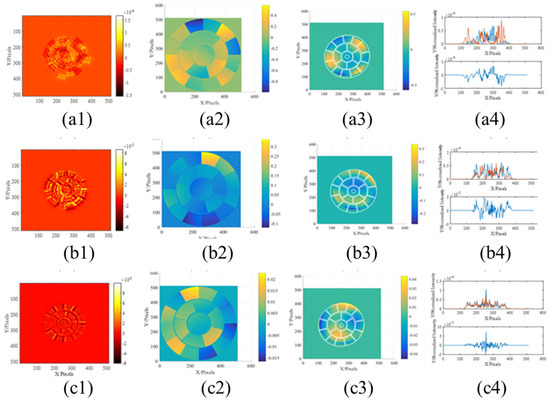
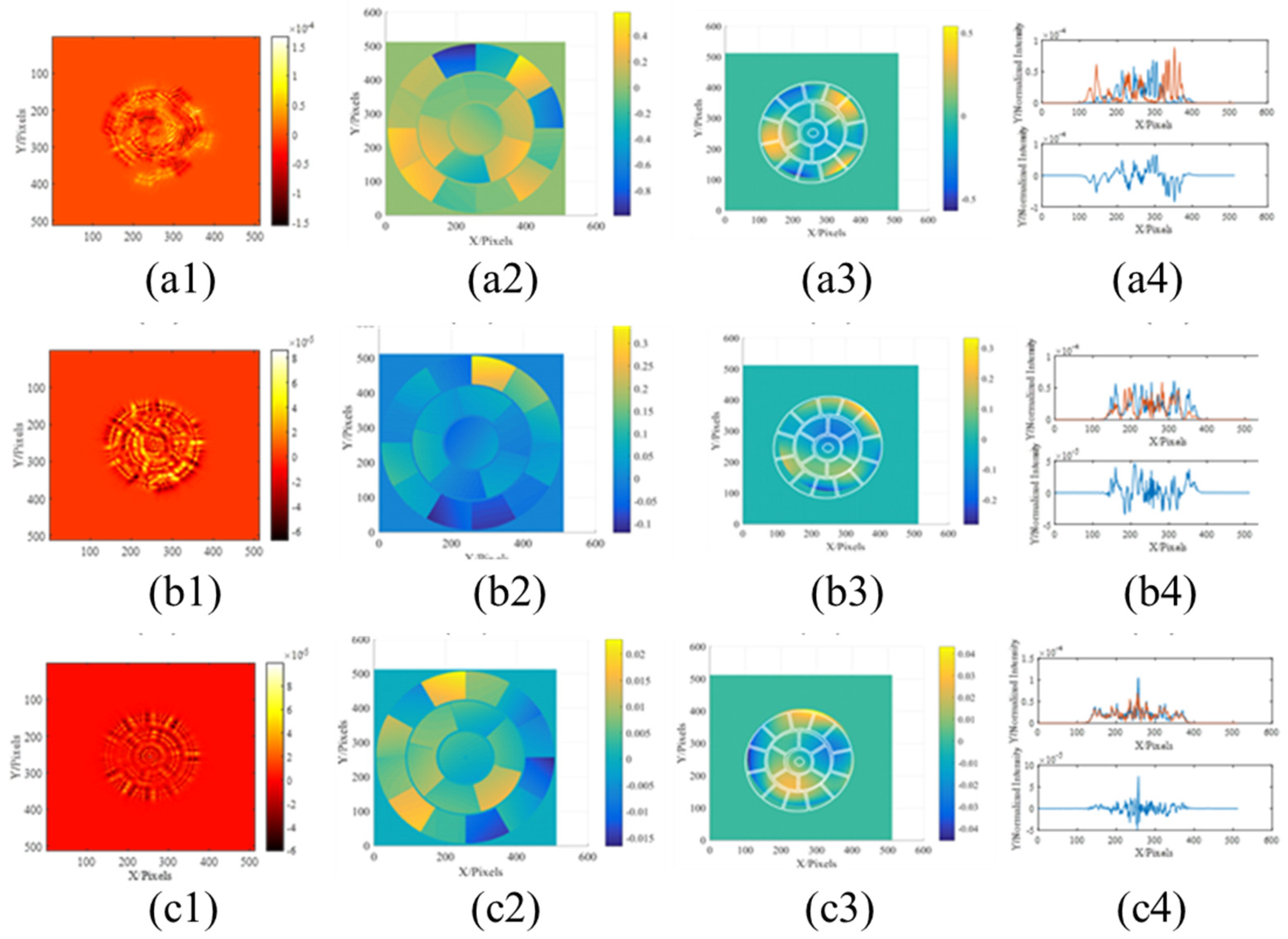
Figure 14 demonstrates the curvature sensing results of the segmented wavefronts. The figure illustrates the correction process from an initial high-error state to the final near-diffraction-limited state. The analysis result shows that the reconstructed wavefront maps derived from these signals. Furthermore, Figure 14 also provides cross-sectional intensity plots to quantitatively analyze the intensity discontinuities that characteristically occur at the segment edges. Based on curvature sensing for the detection of mirror tilt and translation, the correlation between the sensing results and the input wavefront exceeded 0.85. Here, sensing refers to the system’s ability to accurately detect and quantify the misalignments (tilt and translation) of the segmented mirrors from the measured intensity signals. Through an iterative correction process, the precision of this sensing can be refined to . This method avoids the drawback of pupil plane sensing—being unable to address both segmented mirror tilt and translation simultaneously—and allows for a response to the mirror’s low-order aberrations and the calibration of the warping harness. The detailed system calibration process, including sensitivity analysis and the reconstruction of the wavefront control matrix, is illustrated in Figure 15.
Figure 14.
Measurement and reconstruction results for a three-stage segmented wavefront correction process. From top to bottom, rows (a1–a4,b1–b4,c1–c4) correspond to the initial uncorrected state, the state after an intermediate local correction, and the final state after global correction, respectively. Columns (1) to (4) display: (1) the reconstructed wavefront map, (2) the differential intensity signal, (3) the input wavefront, and (4) the corresponding cross-sectional intensity profiles.
Figure 15.
System calibration process. Columns A to D present the system’s sensitivity analysis, the tilting operation of a mirror segment, and the calibration of the system’s overall response function, respectively. Based on these calibration results, a complete wavefront control matrix was then reconstructed. Row 1 (a1–d1) and row 2 (a2–d2) illustrate this process under large amplitude and small amplitude conditions, respectively.
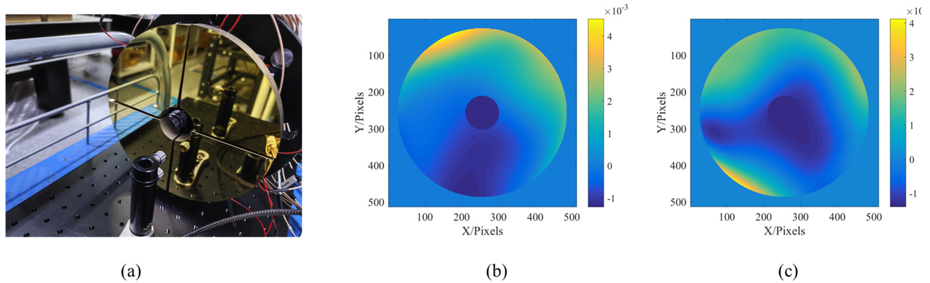
Figure 16 illustrates a four-segment demonstration and verification system. Three actuators on the back adjust the system to co-phase the two sub-mirrors. This adjustment, based on curvature sensing, reduces the RMS wavefront error from 0.0017 units to 0.00098 units.
Figure 16.
Wavefront curvature sensing for precise co-focus state sensing. (a) Physical object of the sector-shaped segmented mirror, (b) residual wavefront error map of the two-mirror system in the precisely co-focused state; (c) residual wavefront error map of the four-mirror system after co-focusing.
In this section, an experiment was performed on the methods listed in the theoretical analysis, and the high-precision performance of the machine-vision-based alignment technique was confirmed. The dispersed fringe co-phasing test and the narrowband method utilized large-scale and high-precision co-phasing measurement and control. We also measured and controlled low-order aberrations and tested ring area splicing stability. Experimental evidence supports the theoretical guidelines/concepts, which state the feasibility of utilizing the novel multimodal testing approach and accompanying techniques for segmented planar mirror systems with a large aperture. The following section further explores the influence and application of the experimental results on different telescopes and scenarios.
5. Discussion
First, this study analyzes the segmentation methods for segmented planar mirrors. High-spatial-frequency fidelity is critical for planar mirror systems in integration and testing to verify system performance and facilitate integration. Due to sampling fluctuations, hexagonal sub-mirror edges easily generate spatial frequency leakage, and they also generate diffraction effects similar to those caused by the support struts (or spiders) of a secondary mirror. Therefore, keystone-shaped segments are a better choice for integration and testing with minimum aperture under seeing-limited conditions.
For large segmented telescopes, the fundamental principles are similar to this study. However, the key difference is that spatial frequency selection must consider practical implementation constraints for different scientific objectives. Because of the large co-phasing areas and limited adjustment degrees of freedom of sparse aperture segmented mirrors. When combined with follow-up optical platforms, they offer significant advantages for high-contrast and high-resolution imaging.
In addition, since the segment sizes close to the atmospheric coherence length, using high fill factor segmentation geometry (such as hexagonal or keystone patterns) can effectively maximize the system’s fill factor and enhance its sensitivity. This approach has application prospects for the systems requiring high light-gathering power under restricted observation conditions (such as survey telescopes and spectral telescopes). Specifically, for telescopes with specific coverage field requirements, the number of sub-mirrors can be reduced by the keystone segments to lower manufacturing cost.
Furthermore, the keystone structure has good application prospects for off-axis mirror applications. Specifically, keystone mirrors allow compensation of curvature radius tolerances in the sagittal plane through positional adjustments. This achieves better imaging quality for back-end slit spectrographs.
6. Conclusions
This research investigates the integration and testing of large segmented planar mirrors with special focus on initial calibration, adjustment of co-focus and co-phasing, and maintenance of wavefront stability during optical relay processes. It formulates a comprehensive methodological framework considering the advantages of architectural design as well as the improvement in detection methodology.
As far as segmentation architecture advantages are concerned, the annular key-stone segmentation architecture was selected and demonstrated with many key benefits: (1) consistent segment geometry preventing complex individual fabrication and permitting mass fabrication at lower cost and consistent optical quality; (2) enhanced rotational symmetry providing greater thermal stability through balanced thermal expansion and equal stress distribution; (3) high spatial frequency coverage enabling optimum imaging performance; (4) inherent coaxial system compatibility, which matches the system’s rotational symmetry with low-order aberrations and simple control algorithms; (5) diffraction artifact suppression via intrinsic circumferential symmetry; and (6) short optical transfer path facilitating efficient alignment. These advantages together overcome the intrinsic shortcomings of conventional hexagonal segmentation methods and provide enhanced integration testability.
For detection methodology innovation, the multimodal test approach demonstrates dramatic improvements: System alignment was achieved through machine vision by utilizing edge gradient detection to achieve large dynamic range and accuracy capability. Wavefront detection was accomplished using discrete sub-apertures in segment gaps, and a far-field spot at the system’s focal plane analysis provided full system characterization. High-throughput, high signal-to-noise edge sensing with a global control matrix and fast-solving algorithms for large-scale issues implemented near-zero-overshoot co-phasing control and inter-segment collision prevention.
This study offers a thorough methodological strategy for the integration and verification of segmented planar mirror systems to provide traceable metrology from the system’s assembly through transport to final operation. Through the synergistic integration of optimal segmentation architecture and the inclusion of innovative detection approaches, we gained superior insight into large-scale segmented optics. The performance is shown to meet sensing and control requirements, achieving co-phasing accuracy better than 30 nm RMS and alignment accuracy below 10 arcseconds. These results represent significant improvements over earlier approaches and establish a solid foundation for future large-aperture telescope technology.
Author Contributions
Conceptualization, Q.A. and X.W.; Writing—original draft, R.S. All authors have read and agreed to the published version of the manuscript.
Funding
This work was supported by the National Natural Science Foundation of China (Grant No. 12133009), the Jilin Provincial Department of Science and Technology (Grant No. 20250101025JJ), and The Science and Technology Application Promotion Fund (Grant No. 145XXX050532000X).
Data Availability Statement
Data underlying the results presented in this paper are not publicly available at this time but may be obtained from the authors upon reasonable request.
Acknowledgments
This research was carried out at the Changchun Institute of Optics, Fine Mechanics and Physics, Chinese Academy of Science. The authors are very grateful to Zhu and Cao for providing valuable suggestions and help.
Conflicts of Interest
The authors declare no conflicts of interest.
References
- Madau, P.; Giallongo, E.; Grazian, A.; Haardt, F. Cosmic Reionization in the JWST Era: Back to AGNs? Astrophys. J. 2024, 971, 75. [Google Scholar] [CrossRef] [Scilit]
- Sanders, G.H. The thirty meter telescope (tmt): An international observatory. J. Astrophys. Astron. 2013, 34, 81–86. [Google Scholar] [CrossRef] [Scilit]
- An, Q.; Zhang, J.; Yang, F.; Zhao, H. TMT Tertiary Mirror Optical Jitter Model Metrology. J. Harbin Inst. Technol. 2016, 23, 67–72. [Google Scholar]
- Prochaska, J.X.; Ratliff, C.; Cabak, J.; Tripsas, A.; Adkins, S.; Bolte, M.; Cowley, D.; Dahler, M.; Deich, W.; Lewis, H.; et al. Detailed design of a deployable tertiary mirror for the Keck I telescope. In Proceedings of the Observatory Operations: Strategies, Processes, and Systems VI, Edinburgh, UK, 26 June–1 July 2016; Volume 9910, pp. 859–880. [Google Scholar]
- Burge, J.H.; Su, P.; Yellowhair, J.; Zhao, C. Optical surface measurements for very large flat mirrors. In Proceedings of the Advanced Optical and Mechanical Technologies in Telescopes and Instrumentation, Marseille, France, 23–28 June 2008; Volume 7018, pp. 408–420. [Google Scholar]
- Vernet, E.; Cayrel, M.; Hubin, N.; Mueller, M.; Biasi, R.; Gallieni, D.; Tintori, M. Specifications and design of the E-ELT M4 adaptive unit. In Proceedings of the Adaptive Optics Systems III, Amsterdam, The Netherlands, 1–6 July 2012; Volume 8447, pp. 1991–1998. [Google Scholar]
- Chen, S.; Dai, Y.; Li, S.; Peng, X.; Wang, J. Error reductions for stitching test of large optical flats. Opt. Laser Technol. 2012, 44, 1543–1550. [Google Scholar] [CrossRef] [Scilit]
- Zhao, C.; Sprowl, R.A.; Bray, M.; Burge, J.H. Figure measurement of a large optical flat with a Fizeau interferometer and stitching technique. In Proceedings of the Interferometry XIII: Applications, San Diego, CA, USA, 13–17 August 2006; Volume 6293, pp. 160–168. [Google Scholar]
- Zhang, Y.; Cui, X.Q. Calculations for the pre-calibration of LAMOST active optics. Chin. J. Astron. Astrophys. 2005, 5, 302. [Google Scholar] [CrossRef] [Scilit]
- Vernet, E.; Pirard, J.-F.; Hauck, C.A.; Ramirez, P.Z.; Cayrel, M.; Lamour, C.; Carel, J.L.; Merceron, J.M.; Doublet, S.; Charuel, C.; et al. ESO ELT M5 unit: Design and manufacturing status. In Proceedings of the Ground-based and Airborne Telescopes VIII, Online, 14–18 December 2020; Volume 11445, pp. 729–738. [Google Scholar]
- An, Q.; Zhang, J.; Yang, F.; Zhao, H. Metrology and calibration of GSSMP rotation accuracy. Infrared Laser Eng. 2018, 47, 917004. [Google Scholar] [CrossRef] [Scilit]
- Johns, M.; Hull, C.; Muller, G.; Irarrazaval, B.; Bouchez, A.; Chylek, T.; Smith, C.; Wadhavkar, A.; Bigelow, B.; Gunnels, S.; et al. Design of the giant magellan telescope. In Proceedings of the Ground-based and Airborne Telescopes, V, Montréal, QC, Canada, 22–7 June 2014; Volume 9145, pp. 519–532. [Google Scholar]
- Kimble, R.A.; Davila, P.S.; Diaz, C.E.; Feinberg, L.D.; Glazer, S.D.; Jones, G.S.; Marsh, J.M.; Matthews, G.W.; McGuffey, D.B.; O’Rear, P.H.; et al. The integration and test program of the James Webb Space Telescope. In Proceedings of the Space Telescopes and Instrumentation 2012: Optical, Infrared, and Millimeter Wave, Amsterdam, The Netherlands, 1–6 July 2012; Volume 8442, pp. 916–930. [Google Scholar]
- Menzel, M.; Parrish, K.; Feinberg, L.; Geithner, P.; Van Campen, J.; McElwain, M.; Irish, S. Lessons learned from systems engineering on the James Webb Space Telescope. J. Astron. Telesc. Instrum. Syst. 2024, 10, 011208. [Google Scholar] [CrossRef] [Scilit]
- Bell, R.M.; Robins, G.C.; Eugeni, C.; Cuzner, G.; Hutchison, S.B.; Baily, S.H.; Ceurden, B.; Hagen, J.; Kenagy, K.; Martin, H.M.; et al. LOTIS at completion of collimator integration. In Proceedings of the Modeling, Systems Engineering, and Project Management for Astronomy III, Marseille, France, 23–28 June 2008; Volume 7017, pp. 123–135. [Google Scholar]
- Cho, S.-Y.; Seo, S.-W.; Brooke, M.A.; Jokerst, N.M. Integrated detectors for embedded optical interconnections on electrical boards, modules, and integrated circuits. IEEE J. Sel. Top. Quantum Electron. 2002, 8, 1427–1434. [Google Scholar]
- Pica, G.; Ciofaniello, L.; Mattei, S.; Santovito, M.R.; Gardi, R. High-resolution deployable telescope for satellite applications. In Proceedings of the Sensors, Systems, and Next-Generation Satellites VII, Barcelona, Spain, 8–12 September 2004; Volume 5234, pp. 531–538. [Google Scholar]
- Hansen, J.T.; Ireland, M.J.; Laugier, R. Large Interferometer For Exoplanets (LIFE)-VII. Practical implementation of a five-telescope kernel-nulling beam combiner with a discussion on instrumental uncertainties and redundancy benefits. Astron. Astrophys. 2023, 670, A57. [Google Scholar] [CrossRef] [Scilit]
- Rediker, R.; Lind, T.; Burke, B. Optical wavefront measurement and/or modification using integrated optics. J. Light. Technol. 1988, 6, 916–932. [Google Scholar] [CrossRef] [Scilit]
- Stoklasa, B.; Motka, L.; Rehacek, J.; Hradil, Z.; Sánchez-Soto, L.L. Wavefront sensing reveals optical coherence. Nat. Commun. 2014, 5, 3275. [Google Scholar] [CrossRef] [Scilit] [PubMed]
- An, Q.; Zhang, H.; Wang, K.; Liu, X.; Li, H. Photonics Scanning Pentaprism System for the Integrated Inspection of Large-Aperture Telescopes. Sensors 2023, 23, 6650. [Google Scholar] [CrossRef] [Scilit] [PubMed]
- Goodman, J.W. Introduction to Fourier Optics, 3rd ed.; Roberts & Company Publishers: Greenwood Village, CO, USA, 2005; Chapter 6; pp. 126–154. [Google Scholar]
- Tong, J.; Shi, H.; Wu, C.; Jiang, H.; Yang, T. Skewness correction and quality evaluation of plug seedling images based on Canny operator and Hough transform. Comput. Electron. Agric. 2018, 155, 461–472. [Google Scholar] [CrossRef] [Scilit]
- Golnabi, H.; Asadpour, A. Design and application of industrial machine vision systems. Robot. Comput.-Integr. Manuf. 2007, 23, 630–637. [Google Scholar] [CrossRef] [Scilit]
- Boissenin, M.; Wedekind, J.; Selvan, A.; Amavasai, B.; Caparrelli, F.; Travis, J. Computer vision methods for optical microscopes. Image Vis. Comput. 2007, 25, 1107–1116. [Google Scholar] [CrossRef] [Scilit]
- An, Q.; Wang, K.; Liu, X.; Li, H.; Zhu, J. Integrated Test System for Large-aperture Telescopes Based on Astrophotonics Interconnections. Instrumentation 2024, 11. [Google Scholar] [CrossRef]
Disclaimer/Publisher’s Note: The statements, opinions and data contained in all publications are solely those of the individual author(s) and contributor(s) and not of MDPI and/or the editor(s). MDPI and/or the editor(s) disclaim responsibility for any injury to people or property resulting from any ideas, methods, instructions or products referred to in the content. |
© 2026 by the authors. Licensee MDPI, Basel, Switzerland. This article is an open access article distributed under the terms and conditions of the Creative Commons Attribution (CC BY) license.