


Abstract
To address the urgent need for new satellite constellations for high-speed communication and high-precision orbit determination, this paper designs an intersatellite heterodyne coherent laser mixed-domain integrated communication and ranging system, achieving deep integration of communication and ranging functions. The system combines analog-domain linear equalization with a digital-domain feedback mechanism to establish an integrated processing strategy for clock and data recovery (CDR), along with high-precision ranging. A phase-augmented pseudo-noise ranging dual one-way ranging (PAPR-DOWR) scheme is implemented, which accurately accomplishes intersatellite distance resolution through the synergy between coarse measurements via frame-synchronization matched filtering and fine measurements via an optimized Gardner timing recovery algorithm.Thetest platform of the on-orbit experiment is a medium Earth orbit (MEO) satellite at an altitude of approximately 20,000 km, the two laser terminals under test are separated by approximately 50,000 km, and the Doppler frequency shift is within GHz. The experimental results show that at a symbol rate of 1.023 Gsps, the system achieves ranging standard deviations of 4.39 ps (approximately 1.3 mm, ) in a ground-based 4000 s long-term test and 5.69 ps (approximately 1.7 mm, ) in an on-orbit short-term dynamic test, fully demonstrating millimeter-level ranging performance under long-distance, low-SNR intersatellite conditions.
1. Introduction
The autonomous determination of high-precision intersatellite spatial inertial coordinates has become a core prerequisite for ensuring precise orbit maintenance and efficient system operation [1,2,3,4] with the rapid development of global navigation satellite systems (GNSS), low earth orbit (LEO) communication and navigation constellations, and lunar and deep space exploration networks. Traditional intersatellite links mainly rely on microwave frequency bands to provide ranging and communication. Their ranging accuracy is usually limited to the decimeter level, and the communication rate is only on the order of tens of thousands of bits per second, which can no longer meet the application requirements of the new generation of constellation systems for centimeter-level high-precision orbit determination, massive broadband data backhaul, and autonomous spacecraft orbit determination [5,6]. Relying on extremely high operating carrier frequencies and extremely narrow beam divergence angles, intersatellite laser links offer both high-speed communication and high-precision ranging capabilities and are becoming a key technology driving the upgrade of future space network architectures [7,8].
To meet the high requirements of modern spacecraft for payload lightweighting and multi-functional integration, the “integrated laser ranging and communication” technology has emerged [9,10,11]. The core of this technology lies in breaking the architecture of physical isolation between traditional ranging and communication subsystems, and achieving “one transmission, dual reception” of signals by sharing the same set of optical antennas, laser sources, and core signal processing links. While significantly reducing payload redundancy, system power consumption, and physical volume, this architecture can improve intersatellite ranging accuracy from the decimeter level to the centimeter or even millimeter level and increase the communication rate to more than hundreds of Mbps [9]. This not only substantially improves the resource utilization efficiency and operational reliability of the system but also provides strong support for the long-term autonomous operation and precise orbit maintenance of constellations from the underlying hardware architecture. The feasibility of this integrated architecture rests on coherent detection with digital signal processing, whose sensitivity and spectral-efficiency advantages over intensity-modulation and direct-detection links were established in the foundational work on coherent optical communications by Kikuchi [12] and in the comparative study of modulation and detection techniques by Kahn and Ho [13].
Currently, multiple studies and experiments have been conducted on intersatellite laser links and integrated ranging-and-communication technologies [14,15,16,17,18]. The GRACE-FO gravity measurement mission jointly implemented by NASA of the United States and GFZ of Germany carries a laser ranging interferometer (LRI) [19], which achieves nanometer-level ranging accuracy at an intersatellite distance of approximately 220 km [15,20]. In addition, researchers from the Massachusetts Institute of Technology systematically demonstrated the application potential of intersatellite laser links in relative position vector measurements, indicating that autonomous navigation accuracy at the meter-level to decameter-level can be achieved in low-Earth, geosynchronous, and even Mars orbits [17]. Table 1 summarizes the reported performance of representative intersatellite laser ranging approaches, including the GRACE-FO interferometer and coherent communication links with clock phase-difference ranging.
Table 1.
Comparison with representative state-of-the-art intersatellite laser ranging systems.
Focusing on the integrated technology of intersatellite laser ranging and communication, this study designs and implements a heterodyne coherent laser mixed-domain joint reception and demodulation processing system. The main work includes establishing an integrated architecture that combines clock and data recovery with precision ranging, accurately calculating the light propagation delay based on the phase deviation between the transmitted frame synchronization signal and the local clock, and achieving deep reuse of physical resources for communication and ranging systems. Simultaneously, at the algorithm level, this study establishes a phase-augmented pseudo-noise ranging dual one-way ranging (PAPR-DOWR) framework: coarse measurement is first completed through matched filtering of the frame synchronization header, and then fine measurement was achieved by extracting the symbol phase via the optimized Gardner timing recovery loop. In addition, a signal amplitude phase-detector gain correction is introduced before error detection to improve measurement accuracy. In terms of experimental verification, this study builds an experimental platform based on a 130 mm aperture laser terminal and conducts tests under the conditions of a 1.023 Gsps symbol rate and LDPC (8160, 7136) decoding. The ground-based 4000 s long-term test achieved a ranging accuracy of 4.39 ps (approximately 1.3 mm), and the on-orbit short-term dynamic test achieves an accuracy of 5.69 ps (approximately 1.7 mm), fully demonstrating the system’s millimeter-level ranging capability in long-distance, high-dynamic, low-SNR environments.
2. System Scheme and Algorithm Design
This section describes the design of an intersatellite laser heterodyne coherent receiving system architecture and a mixed-domain equalization scheme. Facing stringent demands for high sensitivity and low power consumption in modern satellite space laser communication under ultra-long distance (tens of thousands to hundreds of thousands of kilometers) and high-speed (1∼10 Gbps) scenarios, this system adopts a mixed-domain architecture with collaborative processing in both analog and digital domains, achieving efficient hardware integration of ranging and communication demodulation. This scheme effectively breaks through the power consumption bottleneck caused by high-speed signal processing in traditional all-digital coherent detection, while significantly reducing the requirements for the spectral stability of the laser source in the analog optical phase-locked loop (OPLL).
2.1. System Scheme Design
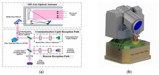
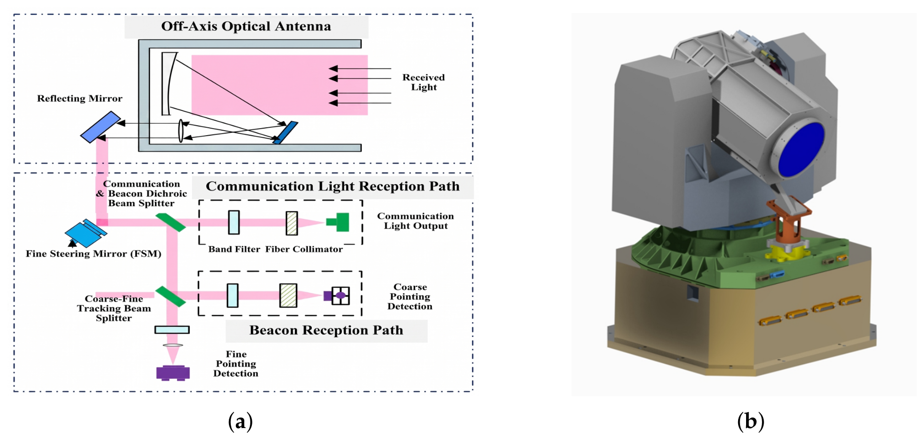
In the space laser communication system, the signal light for both transmission and reception is selected in the 1550 nm band, while the beacon light is selected in the 808 nm band. The optical system design mainly includes a telescope unit and a rear optical path unit, as shown in the Figure 1. The main telescope of the telescope unit (with an optical aperture of 130 mm) is mainly used for the transmission and reception of laser signals and adopts an off-axis configuration. The two-axis gimbal of the telescope is mainly responsible for high-precision pointing and tracking as well as laser signal transmission. The PAT (Pointing, Acquisition, and Tracking) electronic control system is mainly responsible for precise beam pointing, target acquisition, and dynamic tracking. The rear optical path unit is mainly used for laser signal shaping, beam compression, and fiber-coupled transmission and reception. Specifically, the beacon light is received by a large-format CMOS detector, whereas the signal light is directly fiber-coupled and then photoelectrically converted by a balanced photodetector with a 30 μm active area. The laser source is a RIO ORION 1550 nm laser module whose linewidth is better than 10 kHz, and the balanced photodetector is a fiber-coupled receiver from Discovery Semiconductors (model DSC-R412) whose noise-equivalent power is 40 pW/Hz0.5 at the 1550 nm operating wavelength. The communication signal light is output through a fiber collimator and then sent to the rear optical path for frequency conversion and heterodyne processing.
Figure 1.
Block diagram of the optical system design and appearance of the telescope unit: (a) block diagram of the optical system design; (b) appearance of the off-axis optical path telescope.
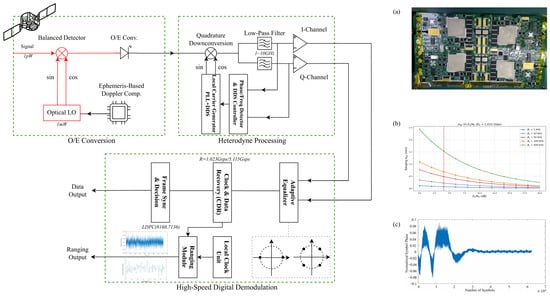
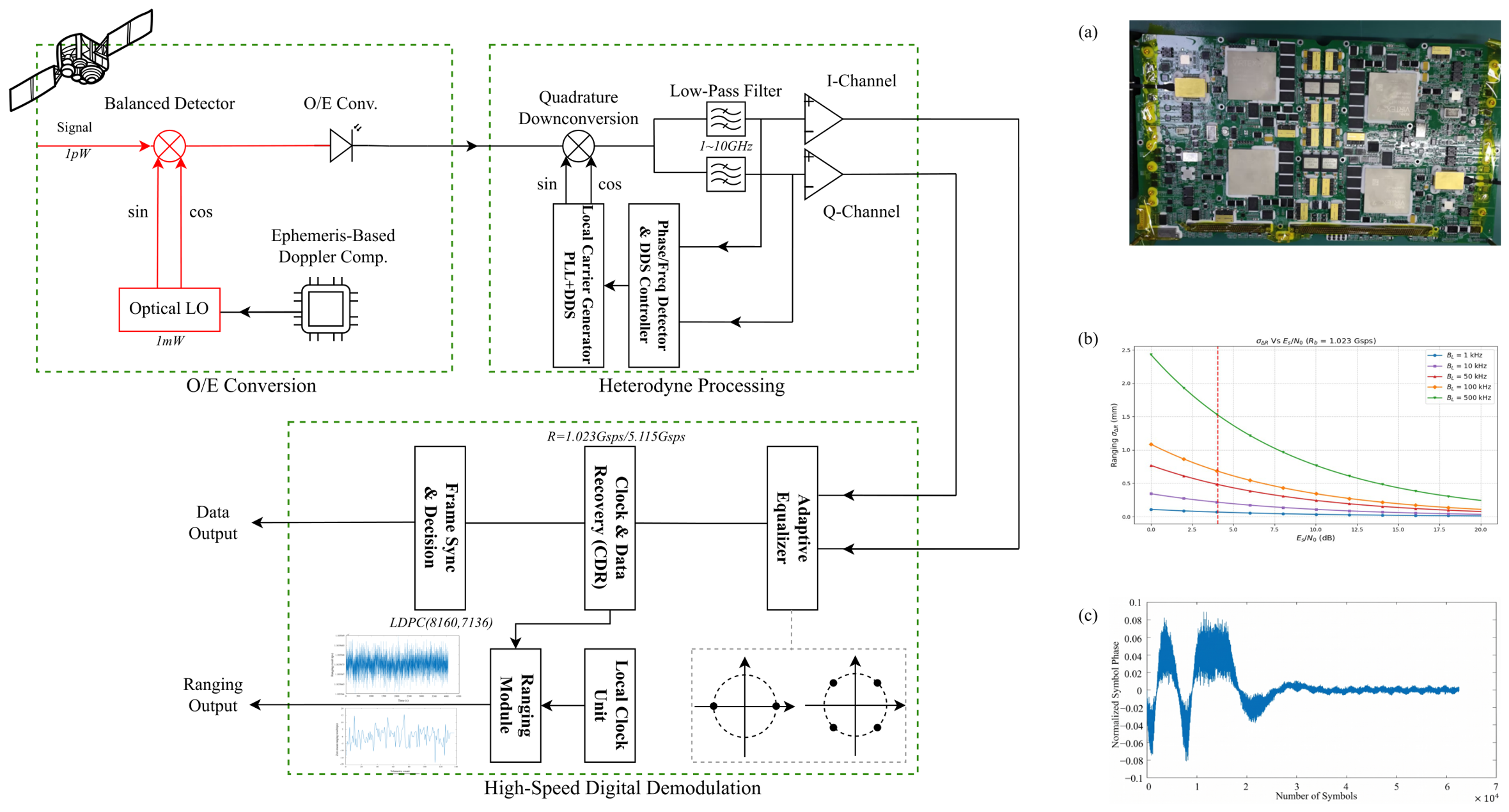
As shown in Figure 2, the received optical signal is first optically mixed and photoelectrically converted using a balanced detector. The system pre-compensates based on the ephemeris-predicted Doppler frequency shift by controlling the local oscillator laser, and the signal then enters the heterodyne processing module. This module adopts a mixed architecture of a direct digital frequency synthesizer and phase-locked loop (DDS + PLL) to generate an orthogonal local oscillator signal, which undergoes orthogonal mixing with the photoelectrically converted signal. The baseband signal from the mixer is sampled by a multiplier and low-pass filtered by a digital frequency discriminator, and then drives the DDS to accurately track the residual Doppler frequency offset and complete carrier stripping. After the phase-locked loop is locked, the demodulated baseband signal is sent to the high-speed digital demodulation module to sequentially complete the channel equalization, clock recovery, and data decision. The analog-to-digital conversion in this module is performed by an Analog Devices AD9213-10G converter with a resolution of 12 bits and a sampling rate of 10.25 Gsps; at the maximum input signal bandwidth of 4000 MHz (peak analog bandwidth 6500 MHz), its effective number of bits (ENOB) is 8.1 bits.
Figure 2.
Block diagram of the heterodyne coherent mixed-domain communication and ranging integrated demodulation principle in space laser.
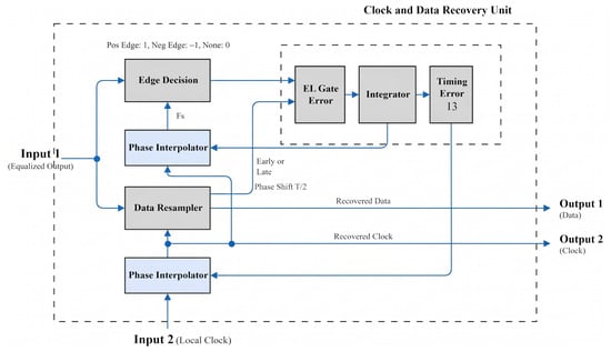
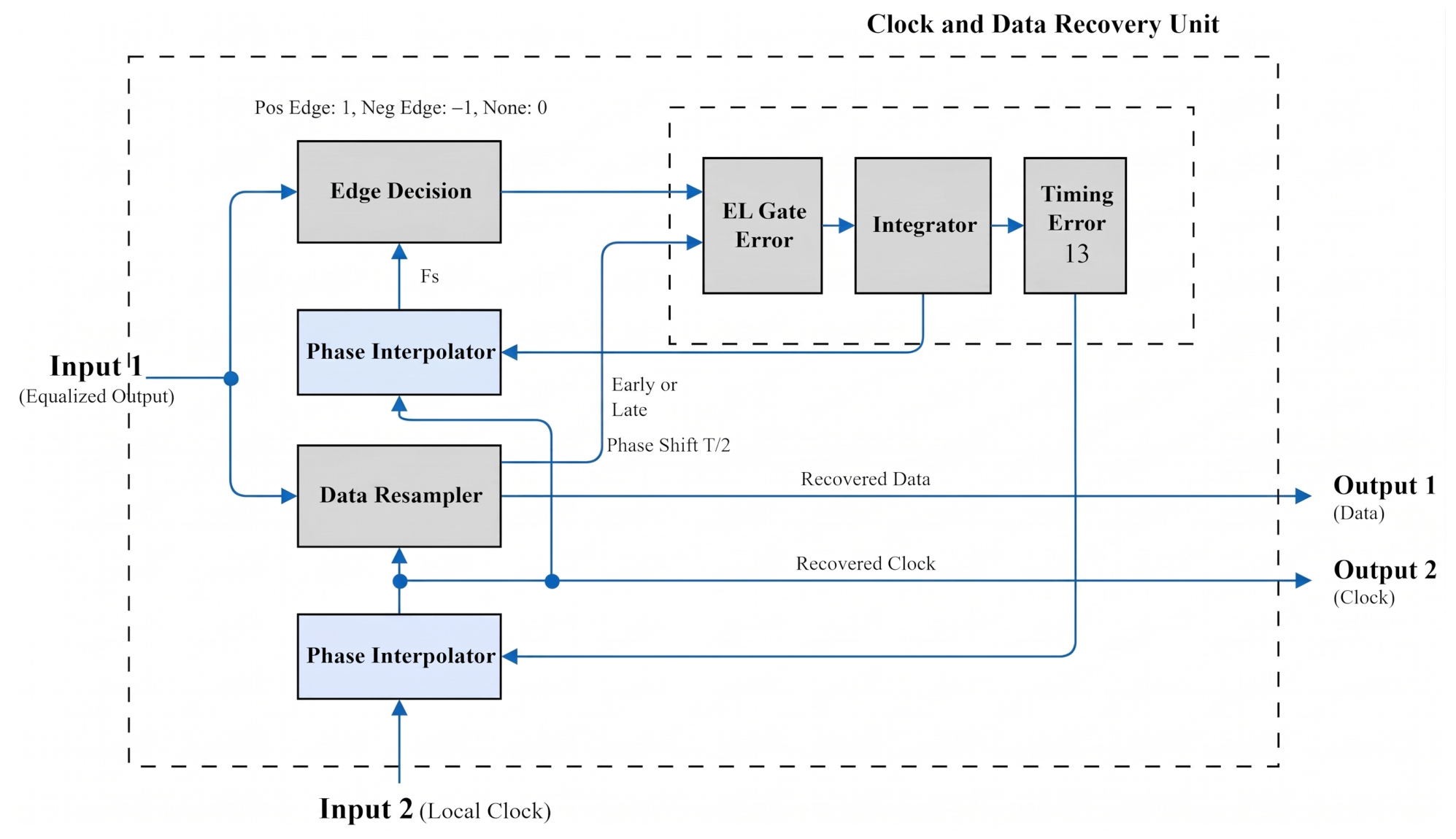
High-speed digital demodulation processing adopts a mixed adaptive equalization architecture that is cascaded in the analog and digital domains. The front-end analog domain uses a two-stage linear equalizer to compensate for mid-to-high frequency power imbalances, and the back-end digital domain uses a decision feedback equalizer (DFE) to dynamically eliminate nonlinear distortions. Subsequently, the all-digital clock and data recovery (CDR) unit achieves synchronization based on closed-loop phase control, as shown in Figure 3: after the edge decision of the input code stream, it is sampled by a dual-phase interpolator driven by a local reference clock; the early-late gate error detector calculates the phase error and feeds back to adjust the phase interpolator, forming a closed-loop sampling control. On this basis, taking the frame synchronization pulse at the transmitting end as a reference, the ranging unit records the count values of the “recovered clock” and the “local clock” in parallel, calculates the light propagation delay through hardware subtraction, and achieves high-precision intersatellite ranging without occupying communication bandwidth. Finally, the serial bit stream output by the CDR is processed by a series-to-parallel converter and frame synchronizer to output the demodulated service data.
Figure 3.
Structural block diagram of the clock and data recovery unit.
2.2. Algorithm Design
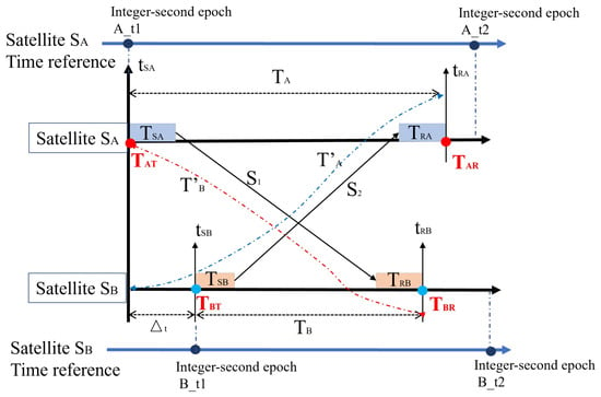
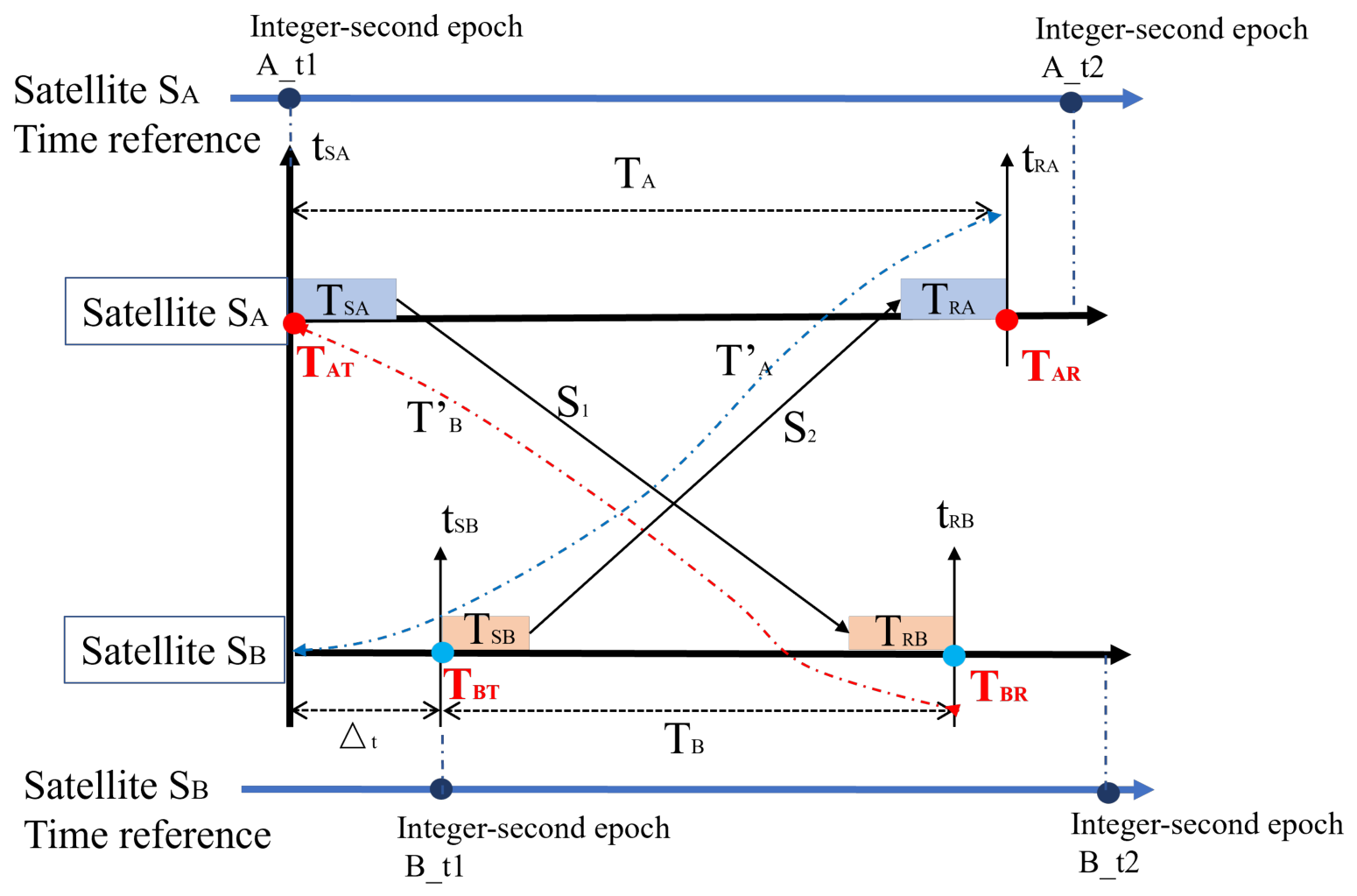
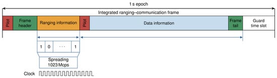
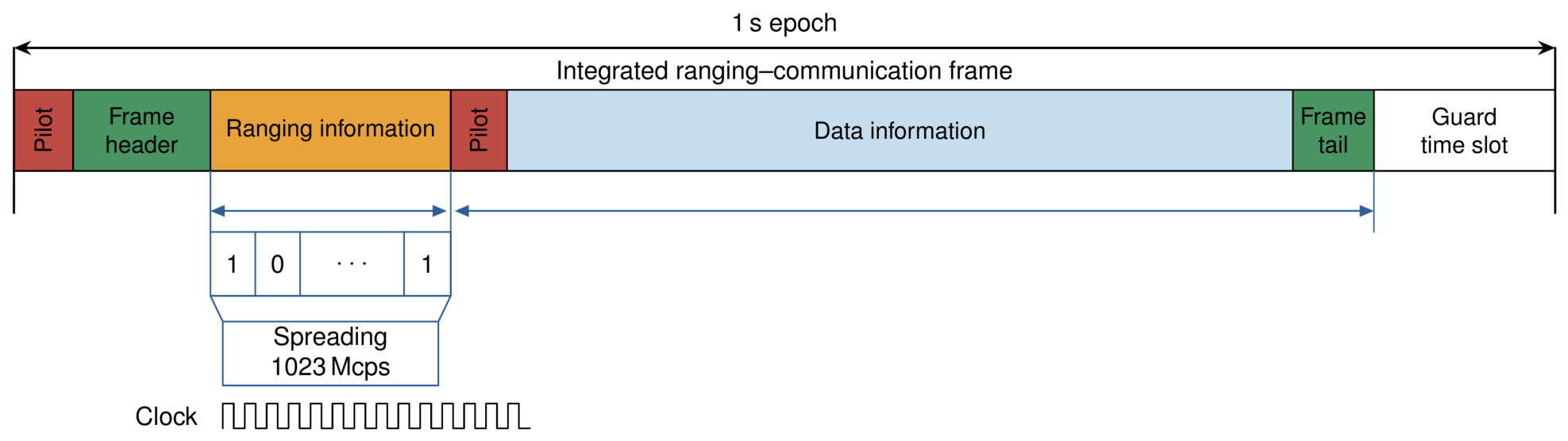
Based on the aforementioned system architecture for ranging and communication, this study designs and implements a PAPR-DOWR ranging-and-communication scheme [22,23]. As shown in Figure 4, the two laser terminals participating in synchronization are denoted as and , and are deployed on two different satellites [21]. The system uses the alignment of the rising edge of the pulse-per-second (PPS) signal with the falling edge of the last bit of the frame synchronization header as the time reference. It should be noted that there is no communication-only mode in this work: communication and ranging are implemented by a single integrated communication-and-ranging frame. The ranging frame is transmitted at a fixed period, and, as shown in Figure 5, the falling edge of the last bit of the frame synchronization header is used as the ranging marker, this pulse being aligned with the integer-second epoch of the clock (1PPS). No data information is transmitted during ranging, so that the main influence of the ranging function is on the information transmission efficiency. When the last bit of the frame synchronization header is transmitted, local timing is initiated, and the timing values are denoted as and , respectively; the timing stops upon receiving a frame synchronization header with the same frame count, and the obtained times are denoted as and , while the second counts and corresponding to that frame are recorded.
Figure 4.
Principle of DOWR measurement.
Figure 5.
Timing relationship among the integrated communication-and-ranging frame, the frame synchronization header, and the 1PPS signal.
The two-way link transmission delays for satellites and are denoted as and , respectively, and their mathematical expressions are as follows [21]:
The ranging time difference between the two satellites:
The relative clock offset between the two satellites:
From the above equations, the following conclusions can be drawn:
- (1)
- The ranging time difference between the two satellites depends on the transmit and receive time differences (, ) and the sum of their respective transmission and reception delays (, );
- (2)
- The time transfer accuracy between the two satellites depends on the transmit and receive time differences (, ) and the difference of their respective transmission and reception delays (, ).
The time-delay difference of the laser transmit and receive channels originates mainly from the optical path, the optical fibre, the collimation/coupling, the detector, the amplitude of the amplifier, and the variation of the clock stability. The calibration is generally carried out first by a ground internal-loopback method: an atomic clock is used as the common reference source, and the transmit channel of the optical path system of the laser terminal is routed through an internal mirror into the receive channel, so that a self-loopback is realised. A high- and low-temperature test is then performed to determine the temperature stability index. The stability is mainly affected by the ambient temperature of the product, remaining in the range of 10∼20 ps/°C.
To implement the above mechanism, the receiving end adopts a time measurement architecture combining coarse measurement and fine measurement:
- (1)
- Coarse measurement: Matched measurement based on the communication frame synchronization header. The receiving terminal internally maintains a fixed 256-bit synchronization feature sequence. The received baseband code stream and local reference sequence undergo continuous sliding integration correlation operations. The successful acquisition of the ranging frame is determined by the correlation peak. The correlation operation expression is given bywhere is the binary code stream of the satellite acquired by the receiving end, and is the locally stored synchronization reference code.During the measurement, the in-second frame count and second count were detected. If they match the agreed values, this moment is recorded as the coarse reception moment. The precision of the coarse moment is related to the symbol rate, and the timing unit is the reciprocal of the symbol rate, denoted as .
- (2)
- Fine measurement: Phase difference measurement based on clock recovery. The demodulation unit is equipped with a parallel Gardner digital clock recovery loop [24,25,26] that can reconstruct the standard timing clock aligned with the transmitting end. The rising edge of this clock accurately falls at the midpoint of each symbol waveform. High-precision time measurements can be achieved by comparing the phase difference between the recovered clock at the receiving end and the local transmission clock. The subdivided duration is , where denotes the subdivided phase value of the fine measurement.
The complete reception moments and of the two satellite terminals are obtained by combining the coarse measurement and the fine measurement subdivided duration:
where and represent the second count values carried by the ranging frames of the two satellites, and and are the subdivided phase radian values detected by the clock loops at both ends.
To reduce the random error of timing measurement and improve ranging accuracy, this study adopts an integrated composite frame design for communication and measurement, superimposing a variable-length pseudo-random ranging code onto the service baseband signal for synchronous electro-optic modulation. The ranging chip rate and communication symbol rate are unified at 1.023 Gsps, and the ranging information bearing rate can be flexibly adjusted within the range of 1∼10 Mbps. This superposition is the phase augmentation referred to by the name of the PAPR-DOWR scheme. The measurement frames carried by the service data are modulated by a spreading code, so that an information rate of 10 Mbps is converted into a symbol rate of Gsps. Because the tracking accuracy of a code loop is typically limited to 0.1∼0.01% of the operating clock rate, a conventional code loop can only operate with a bandwidth of 100 kHz∼1 MHz. After phase augmentation, the code loop of the receiver used in this work can track with a narrow loop bandwidth of 1∼10 kHz. When the linewidth of the local oscillator laser is on the order of 10 kHz, the measurement noise introduced by the code loop is therefore significantly reduced. The optical signal carrying the local high-precision timestamp is sent to the intersatellite space transmission link after optical mixing and power amplification. Integrating the characteristics of photoelectric conversion, coherent mixing, channel noise, and the clock loop, the standard deviation model for timing measurement is derived as
where h is Planck’s constant, is the operating frequency, is the code loop bandwidth, is the quantum conversion efficiency, is the homodyne coherent mixing efficiency, is the symbol-level transition duty-cycle coefficient, is the received optical power, and is the received carrier-to-noise ratio. The received carrier-to-noise ratio is defined by (9), where is the symbol rate. It can be seen from (8) and (9) that the time measurement error decreases as the communication symbol rate and received signal-to-noise ratio increase. Equation (8) follows directly from Equation (9) and from the loop signal-to-noise ratio of the Gardner clock loop, and the intermediate steps of this derivation are given immediately after Equation (9).
It should also be noted that is a dimensionless ratio, whereas the carrier-to-noise-density ratio reported in Section 3.2 is expressed in dB–Hz and satisfies ; is the symbol signal-to-noise ratio used as the decoding threshold in Section 3.2. In gigabit-level intersatellite coherent optical communication scenarios, the bit error rate can be significantly reduced and the measurement accuracy can be improved by increasing the received carrier-to-noise ratio and reducing the clock loop bandwidth.
The phase measurement accuracy depends on the clock and code loop recovery accuracy. The clock and code loop recovery accuracy is related to the clock jitter at the transmitting and receiving ends and the bandwidth of the PLL. In practical implementations, the clock noise used for time synchronization can be ignored, and only the influence of the PLL bandwidth needs to be considered [27]. Aiming at the limitations of traditional designs, this study proposes three key optimization strategies to improve measurement accuracy:
- (1)
- An analog low-pass filter was introduced at the front end of the analog-to-digital converter (ADC) to physically filter out out-of-band noise, effectively suppressing spectral aliasing effects during digital sampling, thereby improving the signal-to-noise ratio of the sampled signal.
- (2)
- A signal amplitude detection module is added before Gardner timing error detection. Amplitude information is used to correct the timing error detection gain coefficient, normalizing the slope near the zero point of the phase detection curve to 1. This eliminates the interference of signal amplitude fluctuations on the timing error detection and reduces the jitter of the convergence curve.
- (3)
- The loop filter parameters (e.g., proportional and integral gains) are finely reconstructed. In particular, the proportional gain and the integral gain are designed jointly, so that the equivalent noise bandwidth of the timing loop is reduced while the loop remains stable; this improves the loop signal-to-noise ratio and, according to Equation (8), reduces the timing standard deviation . By optimizing the parameter configuration, the loop bandwidth is narrowed, and the loop signal-to-noise ratio is improved, which in turn enhances the overall measurement accuracy of the system. A dedicated ablation study that compares the phase jitter and the ranging jitter of the optimized loop with those of a conventional Gardner timing recovery loop will be carried out in future work.
3. Experimental Environment and Test Platform Setup
3.1. Hardware Experimental Platform Construction
To verify the performance of the mixed-domain adaptive equalization and digital loops in the integrated space ranging and communication demodulation system, an experimental hardware platform is established in this study.
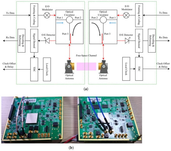
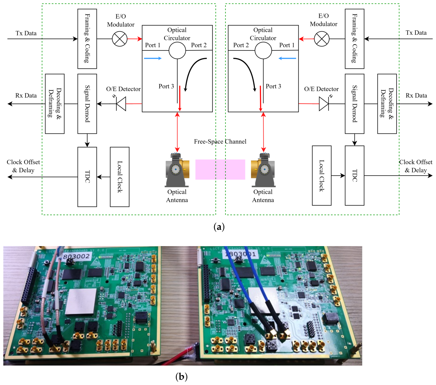
Figure 6 shows the two-way laser link test platform for integrated spatial ranging and communication demodulation, which encompasses optical reception and front-end frequency conversion links. The physical transceiver front end uses the optical head of a standard space laser communication terminal with a 130 mm aperture. The main hardware of the platform is configured as follows: the laser source is a RIO ORION 1550 nm laser module whose linewidth is better than 10 kHz; the balanced detector is a fiber-coupled receiver from Discovery Semiconductors (model DSC-R412); and the digital baseband processing is implemented on a XILINX XC7VX690T-2FFG1157I field-programmable gate array (FPGA). In response to the ultra-wideband characteristics of the 1∼10 GHz baseband signal output by heterodyne mixing, the system first uses a two-stage high-pass linear equalizer in the analog domain to perform hardware frequency-domain gain compensation for the 1∼5 GHz intermediate-frequency component and high-frequency component above 10 GHz. The high-speed sampling and digital baseband core board consists of an analog front end and a digital processing unit. The analog front end incorporates a primary-stage analog low-pass filter before the baseband signal is quantized by the high-speed ADC to suppress out-of-band aliasing noise and improve the sampling signal-to-noise ratio in the passband. The digital processing unit constructs a mixed-signal closed-loop phase interpolator (PI), which can extract a high-precision recovered clock in real-time from the 1∼5 Gsps serial high-speed data stream, providing a stable timing reference for subsequent ranging counting logic.
Figure 6.
Two-way laser link test platform for integrated spatial ranging and communication demodulation: (a) system block diagram; (b) physical image of the experimental platform.
3.2. Experimental Platform Parameter Settings
The signal optical power incident on the remote telescope is set to 1 pW, and the local oscillator laser power is 1 mW. The photodiode responsivity is set to 0.7 A/W, and the heterodyne mixing efficiency of the spatial optical path and the local oscillator light is 0.7. After electrical-domain orthogonal mixing processing, the root mean square (RMS) effective amplitude of the main beat signal is approximately 25 nA. The equivalent linear spectral density of the system’s photocurrent shot noise is 15 pA/. Based on this, the full-link baseline carrier-to-noise ratio is determined to be approximately 64 dB-Hz.
For the integrated joint demodulation of ranging and communication, a rate-7/8 LDPC (8160, 7136) code is selected for baseband channel error correction coding. Under the conventional communication decoding threshold where the bit error rate reaches , the lowest symbol signal-to-noise ratio is set to 4.05 dB. The digital timing recovery loop adopts an improved Gardner closed loop with an embedded adaptive amplitude detection module. The analog-to-digital conversion in the receiver is performed at 10.25 Gsps, that is, at approximately twice the highest baseline symbol rate, and after digital down-conversion and decimation the timing recovery loop operates at 2.01 samples per symbol; between the two samples of each symbol an interpolation filter performs -phase interpolation to refine the recovered timing phase and improve the timing resolution. The simulation platform supports parallel fixed-point simulations at baseline symbol rates of 1.023 and 5.115 Gsps. To suppress the high-frequency noise-induced jitter of ultra-wideband signals, the equivalent noise bandwidth of the Gardner timing recovery loop is subdivided into five configurations: 1, 10, 50, 100, and 500 kHz.
3.3. Static and Dynamic Experimental Design
To comprehensively evaluate the operating stability of the receiving and demodulating processing module under extreme spatial link conditions, two sets of typical test experiments are designed on the platform:
- Experiment 1: Ground-based long-term static precision tracking test.
This test is carried out using a static link in a ground laboratory. The reference standard of this test is the ground test equipment, which uses the same laser and the same optical path as the spaceborne terminal payload, and whose reference clock is provided by two independent rubidium atomic clocks; the fluctuation measured in this way therefore reflects the ranging module under test rather than a difference between the reference and the payload hardware. The system operates in a continuous closed-loop mode at a fixed communication rate, with emphasis on assessing how effectively the algorithm suppresses long-term component temperature drift and the accumulation of thermal noise. Throughout the experiment, loop error signals are recorded continuously to capture the fine-scale phase jitter behavior of the Gardner clock recovery loop. Building on this, the long-term ranging standard deviation is calculated to quantitatively characterise the module’s tracking accuracy and stability under extended static operation.
- Experiment 2: On-orbit short-term dynamic test with large delays.
In this experiment, the test data are obtained directly from an operational on-orbit laser terminal payload. The test platform is a medium Earth orbit (MEO) satellite at an altitude of approximately 20,000 km, and the two laser terminals under test are separated by approximately 50,000 km. The relative velocity between the two terminals is no more than 7.7 km/s, the Doppler frequency shift is within GHz with a Doppler rate of no more than 1.5 MHz/s, and the residual frequency offset after ephemeris-based pre-compensation is within MHz. The received optical input power is no more than dBm, the nominal timing-loop bandwidth settings used in the on-orbit test are 1, 10, 50, and 100 kHz, and the ranging update rate is 0.67 Hz. The objective is to verify the dynamic acquisition accuracy under long-distance space links and weak-light conditions. Due to the dynamic Doppler frequency shift introduced by high-speed relative movement between satellite bodies, the input symbol signal-to-noise ratio exhibits significant fluctuations under link-margin conditions of dB. Both the frequency variation caused by the Doppler effect and the intensity fluctuation caused by atmospheric turbulence can affect the tracking precision of the loop. However, this work is directed at intersatellite laser communication and ranging, so that atmospheric turbulence is not involved in the measurements reported here. With respect to the Doppler effect, the frequency shift of up to GHz and the Doppler rate of less than 1.5 MHz/s are pre-compensated by the ephemeris before heterodyne detection, which brings the residual frequency offset within MHz, after which the laser local oscillator loop achieves lock. The raw observations of the two terminals are exchanged over the communication link, and the transmit and receive channel delays are removed by the algorithm described in Section 2.2; the sum and the difference of the two one-way observations are then formed and combined to obtain the two-way range, and the ranging standard deviation reported for this test is the standard deviation () of the resulting two-way ranging time series over the 130 s measurement window, computed by the same procedure that is applied to the ground-based 4000 s data set of Section 4.2. After completing the dynamic link establishment, the system executes continuous 130 s high-speed data telemetry sampling to verify the operational effectiveness of the integrated ranging unit in the actual on-orbit environment.
The communication performance of the integrated system was also evaluated experimentally. At a communication symbol rate of 5.115 Gsps, the measured bit error rate is before LDPC decoding and 0 after decoding, and the receiver sensitivity reaches dBm. At a communication symbol rate of 1.023 Gsps, the measured bit error rate is before LDPC decoding and 0 after decoding, and the receiver sensitivity is dBm. These results demonstrate that reliable data recovery is obtained after LDPC decoding in both operating modes. The measured communication performance is summarized in Table 2.
Table 2.
Measured communication performance of the integrated system.
4. Test Results and Performance Analysis
4.1. Simulation Analysis of Ranging Error
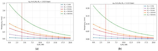
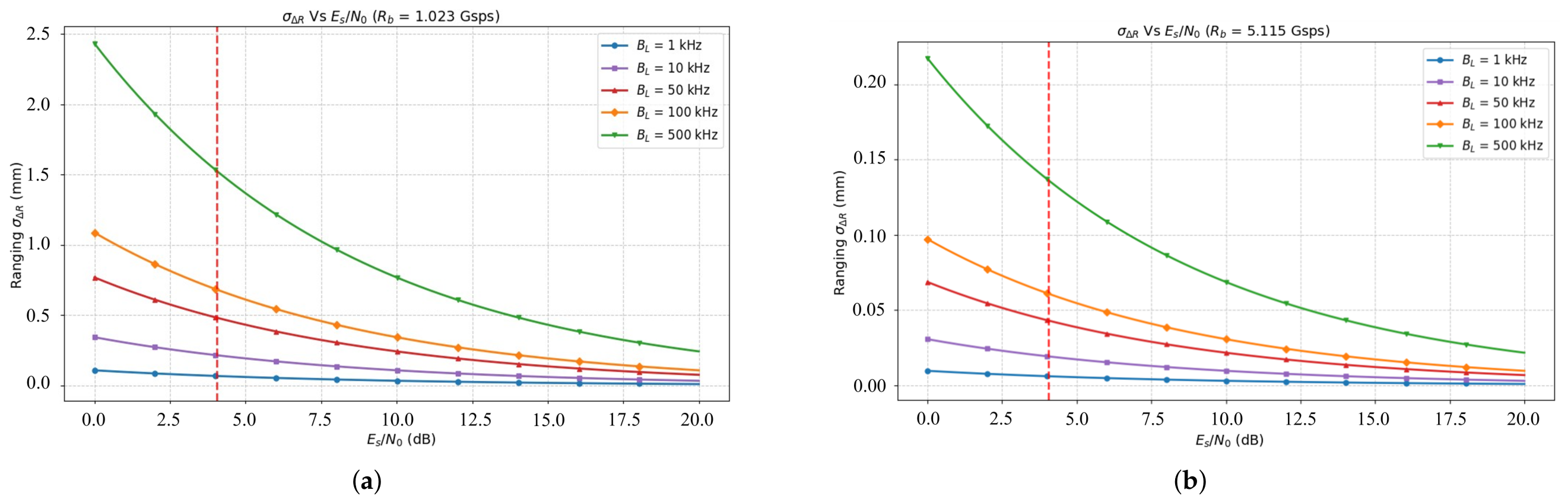
Figure 7 shows the ranging simulation results. The experiment uses LDPC (8160, 7136) coding with a code rate of 7/8, the target bit error rate is set to , and the decoding threshold is dB. The simulation encompasses two symbol rate levels of 1.023 Gsps and 5.115 Gsps and evaluates the ranging performance of the system for loop bandwidths () of 1, 10, 50, 100, and 500 kHz.
Figure 7.
Simulation analysis of ranging error, (a) symbol rate 1.023 Gsps, (b) symbol rate 5.115 Gsps.
As shown in Figure 7, at a symbol rate of 1.023 Gsps, the loop bandwidth significantly affects the ranging accuracy. When the loop bandwidth is 1 kHz (corresponding to spread spectrum mode, information rate 10 Mbps, dB), the ranging root mean square (RMS) error is about 0.3 mm; when the loop bandwidth is increased to 100 kHz (corresponding to non-spread spectrum direct clock synchronization mode), the RMS error rises to 0.7 mm, representing an accuracy difference of about 2.3 times. The results show that at the same communication rate, the spread spectrum technology can effectively compress the loop bandwidth through integral accumulation, thereby significantly improving the ranging accuracy, but at the cost of reducing the information transmission rate from 1 Gbps to 10 Mbps.
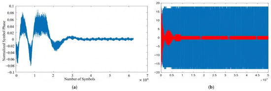
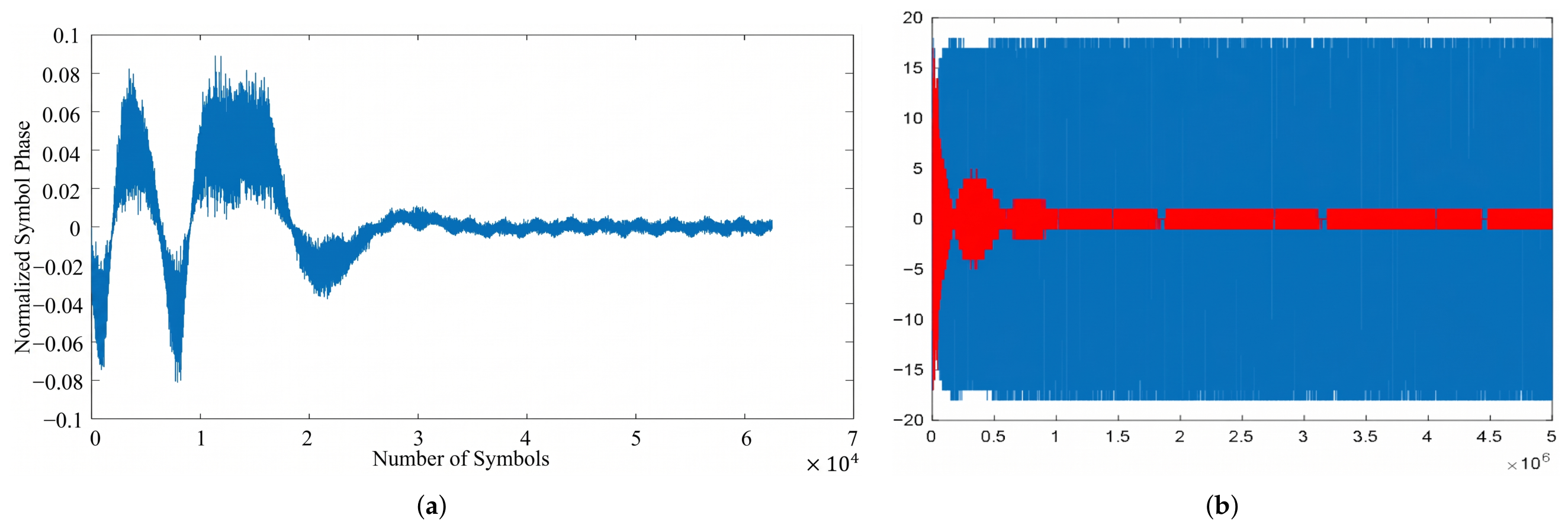
Based on the optimized design of the Gardner algorithm, a parallel fixed-point simulation verification of the synchronization loop is carried out, and the results are shown in Figure 8. At a symbol rate of 1.023 Gsps, the standard deviation of the normalized symbol phase after loop convergence is , and the corresponding theoretical measurement accuracy is approximately . Based on this simulation result, in an actual system design, if the code phase measurement mode overlaid with spread spectrum codes is adopted, the loop bandwidth can be controlled within the range of 1∼10 kHz, while in the measurement mode without overlaid spread spectrum codes, the loop bandwidth can be relaxed to 50∼500 kHz to balance convergence speed and measurement accuracy.
Figure 8.
Simulation results of the Gardner digital clock recovery synchronization loop. (a) Convergence performance of the Gardner loop. (b) I/Q demodulation tracking output (red: I channel, blue: Q channel).
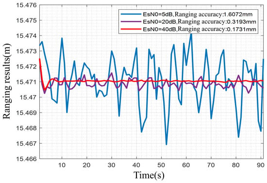
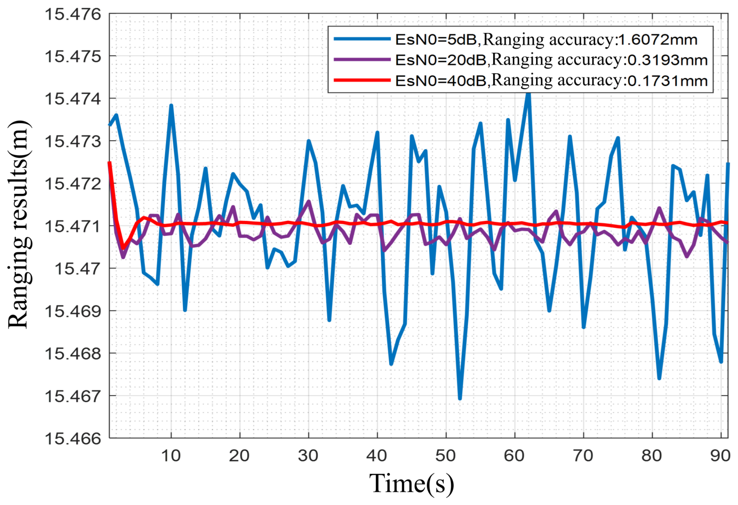
On this basis, by fixing the loop bandwidth kHz and the symbol rate = 1.023 Gsps, simulation analyses are carried out for three signal-to-noise ratio conditions, with at 5, 20, and 40 dB. The results are shown in Figure 9. The simulation results demonstrate that the signal-to-noise ratio has a significant impact on ranging accuracy; in particular, under low carrier-to-noise ratio ( dB) conditions, the ranging error of the system increases significantly, indicating that a low signal-to-noise ratio environment is a key factor restricting high-precision ranging performance.
Figure 9.
Simulation analysis of ranging error: results at different signal-to-noise ratios ( = 5, 20, 40 dB).
4.2. Comparison of Experimental Results
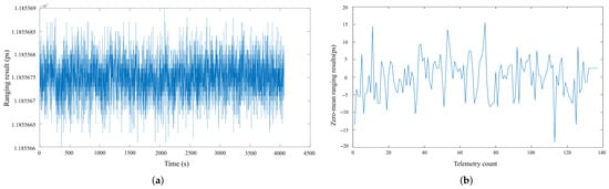
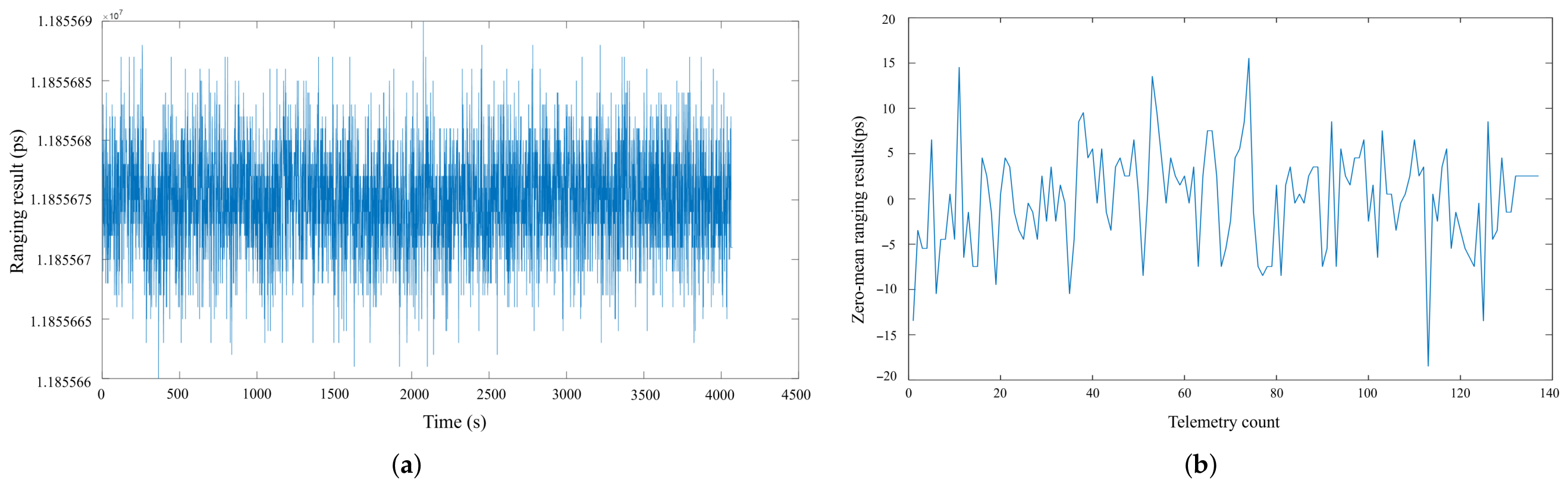
Based on the simulation analysis, this study uses a 130 mm aperture laser terminal to conduct a ranging precision verification experiment, including two scenarios: long-term on the ground (4000 s) and short-term on orbit (130 s, distance 50,000 km). During the test, is maintained at 5∼8 dB. The results are shown in Figure 10. According to the conversion relationship between light propagation time and distance (1 ps corresponds to 0.3 mm), the long-term ranging standard deviation () of 4000 s on the ground is 4.39 ps (corresponding to 1.3 mm), and the short-term ranging standard deviation () on-orbit is 5.69 ps (corresponding to 1.7 mm). The vertical axis of Figure 10a also records the measured absolute distance, whose values lie in the range to .
Figure 10.
Results of laser terminal ranging precision experiments: (a) 4000 s long-term measurement on the ground, the experimental result is a ranging standard deviation of 4.39 ps () at a symbol rate of 1.023 Gsps; (b) short-term on-orbit measurement (130 s, 50,000 km), the experimental result is a ranging standard deviation of 5.69 ps () at a symbol rate of 1.023 Gsps.
Compared with the simulation results (0.7 mm), the ground and on-orbit experimental measurement ranging standard deviations () are 1.3 mm and 1.7 mm, respectively, and the error increases by about a factor of two.
There are three main reasons: first, components such as optical heads and optical amplifiers in the actual optical path introduce extra noise and distortion; second, the long-distance transmission of 50,000 km causes carrier-to-noise ratio fluctuations, affecting signal quality; third, to prevent loop out-of-lock in engineering, the equivalent timing-loop noise bandwidth is relaxed to 20∼50 kHz, sacrificing partial accuracy in exchange for stability. The three contributions can be interpreted quantitatively with the aid of the timing standard deviation model of Equation (8), in which is proportional to the square root of the equivalent noise bandwidth of the clock loop. The 20–50 kHz value denotes the equivalent noise bandwidth of the engineering timing loop; it is not an alternative nominal bandwidth setting in Table 3.
Table 3.
Orbital and link parameters of the on-orbit short-term dynamic test.
The relaxation of the equivalent timing-loop noise bandwidth from the 1–10 kHz range that is available in the spread-spectrum mode to the 20–50 kHz adopted in the engineering implementation is therefore a direct and quantifiable contributor to the observed degradation, while the remaining excess over the simulated 0.7 mm is attributable to the additional noise and distortion of the optical front end and to the carrier-to-noise ratio fluctuation caused by the 50,000 km transmission. The individual contributions are summarized in Table 4. Although there are deviations, the measured results are consistent with the simulation trends, fully validating the rationality and feasibility of the system design.
Table 4.
Ranging error budget of the ground-based and on-orbit measurements.
5. Discussion
The results presented above support three closely related interpretations. First, the mixed-domain heterodyne architecture allows communication and ranging to share the same optical chain and digitized signal-processing path without losing millimeter-level measurement capability. The spread-spectrum mode reduces the effective timing-loop noise bandwidth and improves the simulated ranging precision from about 0.7 mm at 100 kHz to about 0.3 mm at 1 kHz, confirming that symbol-phase jitter is a dominant precision term once frame matching has resolved the coarse range ambiguity. Second, the optimized Gardner loop provides the fine timing reference required by the PAPR-DOWR scheme. Its small residual phase jitter after convergence links a conventional CDR function directly to precision metrology, rather than treating communication recovery and ranging as separate payload tasks. Third, this benefit is conditional: narrowing the loop improves precision but lowers the information rate, so the 1–10 kHz spread-spectrum regime and the 20–50 kHz engineering equivalent-noise-bandwidth regime represent different engineering compromises among acquisition speed, tracking stability, data throughput, and range noise.
These findings should be interpreted in the context of prior intersatellite laser ranging systems (Table 1). The GRACE-FO laser ranging interferometer achieves nanometer-level precision [15,20], but it is a dedicated interferometric instrument operating over a short static baseline, whereas the present system maintains millimeter-level precision over a 50,000 km dynamic link while simultaneously operating at a gigabit-scale symbol rate. LISA-related weak-light ranging and data transmission experiments [18] also demonstrated joint optical measurement and communication, but their measurement formulation and link scale differ from the satellite-terminal implementation examined here. A closer functional comparison is the clock phase-difference method of Zhu et al. [21], whose laboratory precision degraded appreciably when the communication rate was reduced by one order of magnitude. The present on-orbit result was obtained under actual weak-light, long-delay, Doppler-affected conditions, and the superimposed spread-spectrum symbol-phase formulation is designed to be less dependent on the communication rate, giving it practical value for integrated satellite links whose data rates must vary with mission demand. Because these systems use different measurands, integration times, and definitions of ranging error, the comparison indicates relative application domains rather than a strict metrological ranking.
The difference between the 0.7 mm simulation and the measured 1.3 mm ground and 1.7 mm on-orbit standard deviations is also informative. It is not interpreted as a failure of the model, because the engineering system relaxes the equivalent timing-loop noise bandwidth from the narrower spread-spectrum value to 20–50 kHz, and because the optical head, optical amplifier, carrier-to-noise-ratio fluctuation, residual Doppler, and transceiver delays introduce noise that is not fully represented in the timing-loop simulation. The error budget in Section 4.2 consequently attributes the excess scatter mainly to bandwidth relaxation and front-end distortion. Nevertheless, some of those contributions are estimated from link parameters rather than isolated by independent on-orbit calibration. The budget should therefore be regarded as an engineering explanation of the dominant error mechanisms, not as a rigorously separated variance decomposition.
Overall, the measurements demonstrate that a compact 130 mm coherent terminal can perform high-speed communication and millimeter-level ranging under a representative MEO link geometry. This is the principal advance of the work: it combines rate flexibility, mixed-domain implementation feasibility, and an on-orbit demonstration within one architecture. The short 130 s orbital window and the temperature-related drift identified in the longer ground test mean, however, that the current evidence establishes feasibility and bounded short-term precision rather than full long-term stability or absolute orbit-determination accuracy. Future Allan-variance analysis, temperature compensation, and loop-optimization ablation would make the error model more quantitative and clarify how each processing improvement contributes to the final ranging performance.
6. Conclusions
This study designed and implemented a heterodyne coherent mixed-domain reception and demodulation scheme for integrated intersatellite laser ranging and communication, combining clock and data recovery with the PAPR-DOWR ranging framework. At a symbol rate of 1.023 Gsps, the system achieved ranging standard deviations of 1.3 mm over a 4000 s ground-based test and 1.7 mm over a 130 s on-orbit test across a link distance of approximately 50,000 km, while maintaining coherent communication reception. Compared with representative intersatellite laser ranging approaches (Table 1), the proposed scheme combines millimeter-level ranging, gigabit-scale symbol rates, and dynamic long-distance link feasibility within a compact terminal, indicating strong engineering value for volume- and power-constrained satellite links. The ranging precision nevertheless depends on the received carrier-to-noise ratio, and long-term stability is affected by temperature drift; future work will focus on Allan-variance characterization, temperature compensation, and ablation studies of the Gardner loop optimizations to further improve the long-term stability of the integrated ranging and communication terminal.
Author Contributions
Conceptualization, J.Z., L.Z. and B.L.; Methodology, J.Z. and X.Z.; Software, J.Z. and L.C.; Validation, J.Z. and Y.L.; Formal analysis, J.Z. and X.Z.; Investigation, B.L.; Resources, L.Z.; Data curation, J.Z. and L.C.; Writing—original draft preparation, J.Z.; Writing—review and editing, Y.L. and X.Z.; Project administration, X.Z.; Funding acquisition, B.L. All authors have read and agreed to the published version of the manuscript.
Funding
This research was funded by the National Natural Science Foundation of China (grant number 62571137), the Natural Science Foundation of Shanghai (grant number 24ZR1407100) and the National Key Research and Development Program of China (grant number 2025YFF0522600 ).
Data Availability Statement
The data that support the findings of this study are available from the corresponding authors upon reasonable request.
Conflicts of Interest
The authors declare no confficts of interest.
References
- Zhou, K.; Li, J.; Zhou, Q.; Ye, N.; Yang, K.; An, J. Modeling and analysis of terahertz inter-satellite communication-ranging system under platform vibrations. IEEE Trans. Commun. 2026, 74, 4772–4788. [Google Scholar] [CrossRef] [Scilit]
- He, H.; Wen, C.-K.; Jin, S.; Li, G.Y. Model-driven deep learning for MIMO detection. IEEE Trans. Signal Process. 2020, 68, 1702–1715. [Google Scholar] [CrossRef] [Scilit]
- Zhu, Y.; Chen, M.; Wang, S.; Hu, Y.; Liu, Y.; Yin, C.; Quek, T.Q.S. Passive inter-satellite localization accuracy optimization in low Earth orbit satellite networks. IEEE Trans. Wirel. Commun. 2025, 24, 2894–2909. [Google Scholar] [CrossRef] [Scilit]
- Gu, X.; Zheng, C.; Li, Z.; Zhou, G.; Zhou, H.; Zhao, L. Cooperative localization for UAV systems from the perspective of physical clock synchronization. IEEE J. Sel. Areas Commun. 2023, 42, 21–33. [Google Scholar] [CrossRef] [Scilit]
- Chen, X.; He, Y.; Hu, W.; Yu, G.; Tian, Y.; Liu, D.; Zhang, Y.; Wang, Z.; Wang, Z. Geometry-based non-stationary inter-large-satellite wireless channel model. IEEE Trans. Wirel. Commun. 2024, 23, 10592–10607. [Google Scholar] [CrossRef] [Scilit]
- Shang, B.; Zhang, S.; Wong, Z.J. Channel modeling and rate analysis of optical inter-satellite link. IEEE Trans. Veh. Technol. 2025, 74, 11650–11655. [Google Scholar] [CrossRef] [Scilit]
- Zhang, Y.; Ding, R.; Qian, Z.; Liu, M.; Liang, Y.; Jiang, H. Research on high-speed clock synchronization technology for inter-satellite coherent laser communication link. In Proceedings of the 2023 3rd International Conference on Communication Technology and Information Technology (ICCTIT); IEEE: Piscataway, NJ, USA, 2023; pp. 80–83. [Google Scholar]
- Wang, G.; Yang, F.; Song, J.; Han, Z. Dynamic laser inter-satellite link scheduling based on federated reinforcement learning: An asynchronous hierarchical architecture. IEEE Trans. Wirel. Commun. 2024, 23, 14273–14288. [Google Scholar] [CrossRef] [Scilit]
- Li, X.; Fan, F.; Yu, H.; Wang, Y.; Dai, X.; Yang, Q.; Liu, R. A bidirectional multi-format/rate-adjustable integrated laser communication system for satellite communication. IEEE Photonics J. 2024, 16, 7301106. [Google Scholar] [CrossRef] [Scilit]
- Tang, J.; Cui, S.; Li, X.; Hao, Y.; Yang, Y.; Hu, W. Integrated high accuracy laser ranging and communication scheme using large dynamic range and low-complexity DSP algorithm. In Proceedings of the 2023 Asia Communications and Photonics Conference/2023 International Photonics and Optoelectronics Meetings (ACP/POEM); IEEE: Piscataway, NJ, USA, 2023; pp. 1–4. [Google Scholar]
- Wang, Y.; Wang, Y.; Zou, Y.; Zhong, L.; Zhang, S.; Yan, Z. An adaptive real-time sub-symbol communication/ranging integrated system based on native hardware. In Proceedings of the 2024 IEEE Opto-Electronics and Communications Conference (OECC); IEEE: Piscataway, NJ, USA, 2024; pp. 1–3. [Google Scholar]
- Kikuchi, K. Fundamentals of coherent optical fiber communications. J. Light. Technol. 2016, 34, 157–179. [Google Scholar] [CrossRef] [Scilit]
- Kahn, J.M.; Ho, K.-P. Spectral efficiency limits and modulation/detection techniques for DWDM systems. IEEE J. Sel. Top. Quantum Electron. 2004, 10, 259–272. [Google Scholar] [CrossRef] [Scilit]
- Shargorodskiy, V.D.; Sumerin, V.V.; Dmitriev, S.V.; Grigoriev, V.N. Spaceborne laser information-measuring systems. Electromagn. Waves Electron. Syst. 2014, 8, 4–10. [Google Scholar]
- Yin, H.; Yan, Y.; Zhu, Z.; Wang, C.; Feng, W.; Huang, Z.; Zhu, J.; Gu, D.; Zhong, M. A concise phase anomaly correction method for GRACE Follow-On laser ranging interferometer measurements. IEEE J. Sel. Top. Appl. Earth Obs. Remote Sens. 2025, 18, 13794–13813. [Google Scholar] [CrossRef] [Scilit]
- Guo, X.; Wang, P.; Wu, H.; Shao, C.; Luo, K. Optical frequency comb multiplexing for precision ranging and high-rate communication in space-borne gravitational wave detection. IEEE Photonics J. 2026, 18, 1501509. [Google Scholar] [CrossRef] [Scilit]
- Davé, P.K.; Cahoy, K. Autonomous satellite navigation using intersatellite laser communications. Adv. Astronaut. Sci. 2020, 171, AAS 19-928. [Google Scholar]
- Esteban, J.J.; García, A.F.; Barke, S.; Peinado, A.M.; Guzmán Cervantes, F.; Bykov, I.; Heinzel, G.; Danzmann, K. Experimental demonstration of weak-light laser ranging and data communication for LISA. Opt. Express 2011, 19, 15937–15946. [Google Scholar] [CrossRef] [Scilit] [PubMed]
- Sheard, B.S.; Heinzel, G.; Danzmann, K.; Shaddock, D.A.; Klipstein, W.M.; Folkner, W.M. Intersatellite laser ranging instrument for the GRACE follow-on mission. J. Geod. 2012, 86, 1083–1095. [Google Scholar] [CrossRef] [Scilit]
- Abich, K.; Abramovici, A.; Amparan, B.; Baatzsch, A.; Okihiro, B.B.; Barr, D.C.; Bize, M.P.; Bogan, C.; Braxmaier, C.; Burke, M.J.; et al. In-Orbit Performance of the GRACE Follow-on Laser Ranging Interferometer. Phys. Rev. Lett. 2019, 123, 031101. [Google Scholar] [CrossRef] [Scilit] [PubMed]
- Zhu, F.N.; Zhou, L.S.; Sun, J.F.; Che, W.B. Time synchronization based on intersatellite laser communication links. Sci. Sin. Phys. Mech. Astron. 2021, 51, 019517. (In Chinese) [Google Scholar] [CrossRef] [Scilit]
- Gardner, F. A BPSK/QPSK timing-error detector for sampled receivers. IEEE Trans. Commun. 1986, 34, 423–429. [Google Scholar] [CrossRef] [Scilit]
- Meyr, H.; Moeneclaey, M.; Fechtel, S.A. Digital Communication Receivers: Synchronization, Channel Estimation, and Signal Processing; Wiley: New York, NY, USA, 1998. [Google Scholar]
- Kim, S.Y.; Suzuki, T.; Kani, J.; Shimada, T. First real-time softwarization of complete coherent DSP stack with Gardner timing and clock recovery. Electron. Lett. 2026, 62, e70594. [Google Scholar] [CrossRef] [Scilit]
- Gong, S.; Xiang, Q.; Yang, Y.; Fan, L.; Jin, Y.; Cheng, C.; Yang, P.; Tang, J.; Zhang, Q.; Zuo, T. Polarization-crosstalk-tolerant baud-rate timing recovery for coherent optical interconnects. J. Light. Technol. 2026, 44, 3341–3347. [Google Scholar] [CrossRef] [Scilit]
- Qu, F.; Li, Z.; Zhang, M.; Tu, X.; Wei, Y. A carrier-based Gardner timing synchronization algorithm for BPSK signal in maritime communication. J. Mar. Sci. Eng. 2023, 11, 829. [Google Scholar] [CrossRef] [Scilit]
- Barletta, L.; Magarini, M.; Scardoni, F.; Spalvieri, A. Impact of loop delay on the performance of Gardner timing recovery. IEEE Photonics Technol. Lett. 2013, 25, 1797–1800. [Google Scholar] [CrossRef] [Scilit]

Disclaimer/Publisher’s Note: The statements, opinions and data contained in all publications are solely those of the individual author(s) and contributor(s) and not of MDPI and/or the editor(s). MDPI and/or the editor(s) disclaim responsibility for any injury to people or property resulting from any ideas, methods, instructions or products referred to in the content. |
© 2026 by the authors. Licensee MDPI, Basel, Switzerland. This article is an open access article distributed under the terms and conditions of the Creative Commons Attribution (CC BY) license.