


Abstract
The middle trough of spirals serves simultaneously as a buffer zone for variations in hydrodynamic parameters and as a region where mineral particles of different densities are prone to mixing, exerting a profound influence on particle-separation effect. This study employed a multi-fluid volume of fluid (VOF) model incorporating the Bagnold effect to simulate the ilmenite–chlorite slurry flow in a custom-designed Φ400 mm short-travel spiral concentrator with three turns. This study systematically investigated the influence of the transverse inclination angle of the middle trough (ranging from 3.5° to 9.5°) on separation indicators, flow film morphology, secondary circulation characteristics, and particle force dynamics. The results indicate that employing a lower transverse inclination angle is more conducive to improving the technical separation indicators for ilmenite and chlorite. When using enrichment ratio and separation efficiency as criteria, the optimal inclination angles range from 3.5° to 5° and 3.5° to 6.5°, respectively. Meanwhile the separation efficiency and its sensitivity to the middle trough transverse inclination angle vary remarkably with different feeding sizes. Feeding of 112 μm ilmenite and 19 μm chlorite yields the premium separation performance and is minimally affected by the middle trough transverse inclination angle. Conversely, as the ilmenite particle size decreases or the chlorite particle size increases, the separation indicators decline but become significantly regulated by the middle trough transverse inclination angle, exhibiting a desirable angle range of 3.5–6.5°. Hydrodynamic parameter analyses indicate that a moderate flow film depth, continuous secondary circulation morphology and stabilizing inner circulation in the middle trough can be obtained at a middle trough transverse inclination angle scope of 3.5–6.5°. Once the inclination angle exceeds 6.5°, a distinct ridge forms in the flow film of the middle trough, and extensive disruptions occur in the outward circulation, which subsequently impedes the outward transport of low-density particles along with the fluid. At a middle trough transverse inclination angle scope of 3.5–6.5°, the Bagnold force exerted on the ilmenite particles in the middle trough remains low during the initial stage of flow field evolution, which favors their retention in the lower fluid layer to become the concentrate product. Concurrently, the chlorite particles near the inner region experience a higher Bagnold force, which facilitates their suspension into the upper outer circulation, thereby amplifying the kinematic differences between the chlorite and ilmenite particles. This study demonstrates that fluid dynamic parameters and the force characteristics of mineral particles can effectively characterize the separation process of mineral particles in spirals.
1. Introduction
Ilmenite is the primary raw material for the global titanium industry and plays a vital role in high-end technological fields, such as aerospace, national defense, and medical devices [1,2,3,4]. China has the world’s largest ilmenite reserves, which are mainly concentrated in Panzhihua of Sichuan Province and Chengde of Hebei Province [5]. Nevertheless, ilmenite resources are generally characterized by low-grade, high-impurity content and fine dissemination. In particular, the average grade of ilmenite in vanadium–titanium magnetite ores of the Panxi region is less than 10%, accompanied by high contents of associated impurities such as calcium and magnesium. In addition, high-grade rutile resources are extremely scarce. These result in low mineral separation efficiency at the upstream end of China’s titanium industrial chain and high import dependence for downstream high-end titanium materials, including aerospace titanium alloys and electronic-grade high-purity titanium, which poses a serious threat to national resource security [6,7,8].
Mineral separation and enrichment are crucial procedures in the exploitation of titanium resources and are essential for improving the comprehensive utilization efficiency of titanium resources [9]. As a classic gravity separation device, the spiral concentrator has been widely used in the combined separation process of ilmenite owing to its simple structure and low energy consumption [10,11,12]. Over decades of development, studies on the separation mechanism and structural optimization of spiral concentrators have been continuously deepened, which has greatly promoted their separation performance [13,14,15,16,17]. Relevant studies have demonstrated that geometric conditions, including cross-sectional shape and wall surface characteristics, can markedly alter the thickness of flow film, Reynolds number distribution and secondary circulation on the trough surface. This further affects the migration behavior of mineral particles and separation performance. The middle trough surface serves not only as a buffer zone for the variation in hydrodynamic parameters but also as a mixing zone for mineral particles with different densities. Meanwhile, the middle trough responds strongly to the adjustment of splitter position [18,19]. Therefore, compared with the outer and inner regions, the geometry of the middle trough has a more pronounced influence. Exploring the effects of middle trough geometric parameters on the flow field and particle-separation behavior of spiral concentrators is of great theoretical and engineering significance for spiral structure optimization and separation performance improvement.
Based on the above background, this study adopts the high-precision numerical calculation model for flow fields and particle motions established in the previous work to simulate and predict the separation process of ilmenite and chlorite particles in a custom-designed Φ400 mm spiral concentrator. The influence of the transverse inclination angle of the middle cross-section line on mineral separation performance is systematically investigated. Furthermore, the effects of this geometric parameter on hydrodynamic characteristics and particle force conditions during the separation process are discussed. This study aims to reveal the regulatory mechanism of the middle cross-section geometry on dynamic parameters and separation performance of the ilmenite–chlorite–water pulp system. The research findings can provide visualized and systematic data support for structural optimization and the in-depth understanding of gravity separation mechanisms in composite force fields.
2. Materials and Numerical Methods
2.1. Cross-Section Geometry of Spiral Concentrator and Adjustment Range of Middle Trough
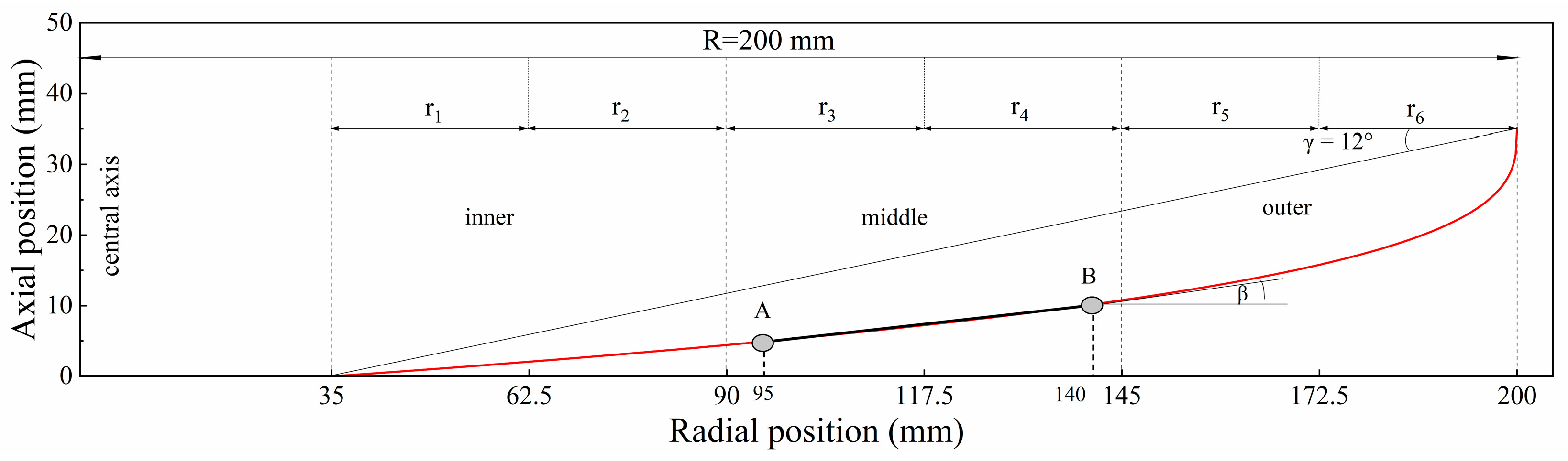
As shown in Figure 1, the cross-section of the spiral concentrator changes gently in the middle trough and is approximately linear, so the curved segment at radial positions r = 95–140 mm was selected for local geometric adjustment and replaced by the line segment AB connecting the two endpoints. This range covers the main approximately linear part of the middle trough while avoiding the transition zones adjacent to the inner and outer trough surfaces. By adjusting the transverse inclination angle of segment AB, the variation trends of pulp flow field parameters and particle-separation behavior were investigated. The spiral concentrator used in the simulation has a diameter of 400 mm and consists of 3.25 turns. The radial adjustment range and transverse inclination angles of the middle trough are listed in Table 1.
Figure 1.
Section geometry and selection of middle trough of spiral concentrator. Note: The red curve represents the original trough, and the black line AB represents the locally adjusted segment.
Table 1.
Adjustment range of the transverse inclination angle of the middle trough.
2.2. Physical Model and Mesh Generation
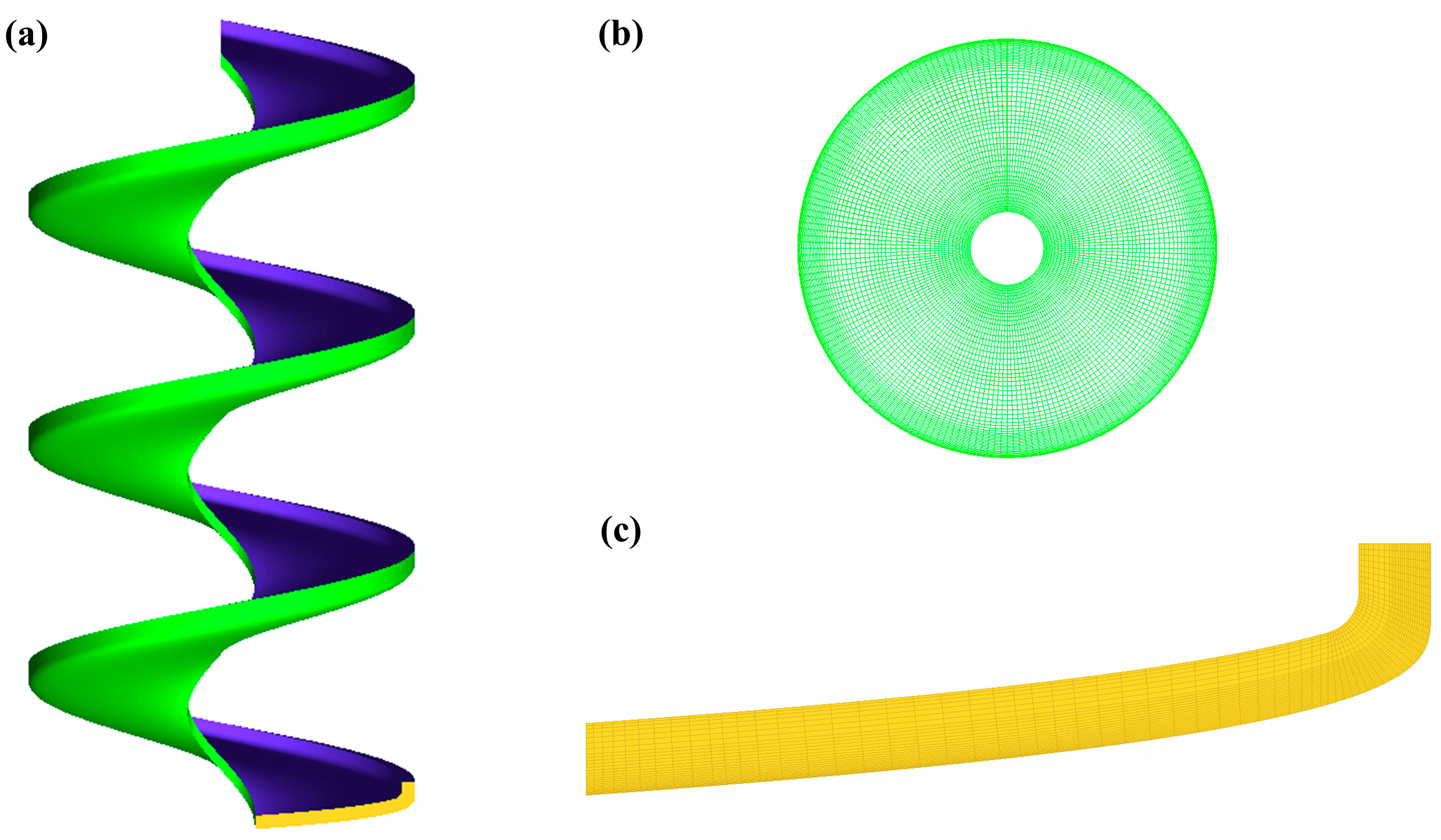
The computational mesh was generated using ICEM CFD 2024 R1 software, and all numerical simulations were performed using the commercial CFD solver ANSYS Fluent 2024 R1. A 3.25-turn spiral concentrator was selected as the simulation object. According to the previous mesh independence test results, the simulation results tend to be stable when the fluid domain of the spiral concentrator with the cross-section of base transverse inclination angle is divided into 1,037,036 hexahedral cells, which can clearly characterize the flow film morphology and the tangential velocity distribution of fluid. The mesh quantity remained unchanged after adjusting the transverse inclination angle of the middle trough. Taking the transverse inclination angle of 6.5° as an example, the mesh generation is presented in Figure 2. To accurately simulate the thin flow film less than 1 mm near the wall surface, local mesh refinement was performed in the near-wall region and outer edge region of the spiral concentrator in this study. After optimization, the minimum mesh height at the bottom wall was 0.15 mm, and the obtained minimum Y+ value was approximately 2.
Figure 2.
Mesh division for the computational domain of the spiral concentrator: (a) computational domain of the spiral concentrator; (b) top view of the wall mesh in the computational domain; (c) mesh division of the outlet.
2.3. Numerical Model and Boundary Conditions
The separation process in the spiral concentrator involves a complex three-dimensional multiphase unpressurized rotational shear flow system. Directly performing gas–liquid–solid three-phase coupling calculation tends to cause instability in numerical solution. Therefore, the VOF multiphase-flow model and RNG k-ε turbulence model were firstly adopted in this study to simulate the gas–liquid two-phase flow field. The governing equations of the VOF model are shown in Equations (1) and (2), while the transport equations for turbulent kinetic energy and turbulent dissipation rate of the RNG k-ε turbulence model are presented in Equations (3) and (4) [20,21,22,23].
where is the volume fraction of the fluid (gas phase or liquid phase); represents the gravitational acceleration; represents the average density of the fluid; and is the effective viscosity of the fluid.
where is the turbulent kinetic energy; is the velocity component in the i-direction; is the turbulent dissipation rate; is the inverse effective Prandtl number for k; is the inverse effective Prandtl number for ; is the turbulent kinetic energy generated by the mean velocity gradient; and denotes the additional strain rate term.
On the basis of stable gas–liquid flow field calculation, the multi-fluid VOF model considering the Bagnold effect was adopted to simulate particle motion. The multi-fluid VOF model is a coupled model combining the VOF model and the Euler–Euler model. The coupled model can identify stratified flow and mixed flow states in the computational domain according to the local interface diffusion index within grid cells and realize the simultaneous simulation of the gas–liquid continuous interface and the discrete phase behavior of particles. Interphase interaction forces include both drag force Fd and lift force Fl. The symmetric model and Gidaspow model were employed to solve the gas–liquid and liquid–solid drag forces, respectively. For the lift force, the Bagnold lift formula was loaded into the lift coefficient module via a user defined function (UDF) for calculation [19,20].
The slurry flow in a spiral concentrator is a shallow, free-surface, unpressurized rotating shear flow characterized by pronounced streamline curvature and moderate turbulence. The RNG k-ε turbulence model was selected based on the work of Doheim et al. [23] and our previous CFD study on the secondary-circulation characteristics of spiral flows [24]. This model has been applied to open-channel and rotating shear flows and provides satisfactory numerical stability in VOF-based free-surface calculations. Moreover, because the present study involves comparative simulations of multiple middle trough transverse inclination angles, the RNG k-ε model provides a reasonable balance between computational cost and the accuracy required for predicting macroscopic flow field characteristics.
For multiphase-flow modeling, the VOF model was first employed to capture the macroscopic gas–liquid free surface. The method for predicting and optimizing mineral-particle-separation indicators in spiral flow films was described in our Chinese patent issued in 2023 [25]. Meng et al. [21] reported and validated a Eulerian multi-fluid VOF framework incorporating the Bagnold effect for particle-flow modeling and separation prediction in spiral concentrators. Accordingly, the VOF model, RNG k-ε turbulence model, and Eulerian multi-fluid VOF model incorporating the Bagnold effect were employed in the present study to characterize the gas–liquid interface, macroscopic particle transport, and separation-indicator variations in the ilmenite–chlorite slurry system under different middle trough transverse inclination angles.
The present numerical framework is primarily intended for macroscopic flow field evolution and separation-index prediction. Instantaneous turbulent structures and particle-scale collision dynamics are therefore not explicitly resolved in the same manner as direct numerical simulation (DNS) and discrete element method (DEM). Considering the feed solid mass fraction of 25% and the need to compare multiple middle-section geometries, the multi-fluid VOF model provides an appropriate balance between computational feasibility and macroscopic separation prediction for this study.
The boundaries of the fluid computational domain mainly include inlet, outlet, upper wall and bottom wall of the trough. The inlet was specified as the velocity inlet boundary, and the outlet was set as the pressure outlet boundary. The trough bottom wall was assigned a no-slip boundary condition, and the standard wall function was adopted for near-wall treatment. The upper wall was defined as a free-slip boundary condition.
The computational time varied slightly depending on the trough geometry and operating conditions. For a representative case, a typical run required approximately 25.5 h to complete the full two-stage calculation. In the numerical calculation, the gas–liquid two-phase flow field was first solved until a stable free-surface flow field was obtained. In this stage, the relative residuals of all governing equations were controlled below 10−4 to ensure the accuracy of the solution. Subsequently, the stable gas–liquid flow field was used as the initial condition for the gas–liquid–solid multiphase-flow simulation. Because the convergence of the multiphase calculation was relatively lower, the residual tolerance was set to below 10−3. After the flow variables reached a stable state, the calculation was continued for an additional 2 s, and the time-averaged results during this period were used as the final simulation results.
2.4. Feed Conditions
In the numerical simulation tests, ilmenite and chlorite were taken as the separation objects. Their densities were set to 4623 kg/m3 and 2626 kg/m3, respectively. Referring to the feed particle size composition and computational workload of the industrial spiral concentrator, ilmenite particles were assigned two average particle sizes of 112 μm and 56 μm, corresponding to the narrow size fractions of −150 + 74 μm and −74 + 38 μm. This arrangement was adopted to explore the differences in motion characteristics and separation performance of ilmenite particles with varying particle sizes. Because chlorite is prone to sliming and generally exists in fine particle sizes during separation, chlorite particles were set at two fine sizes of 56 μm and 19 μm, which were calculated as the average values of the corresponding size fractions, i.e., (74 + 38)/2 = 56 μm and 38/2 = 19 μm. The above ilmenite and chlorite particles formed different feedings, and numerical simulation tests of separation in spiral troughs were carried out accordingly. Ilmenite and chlorite of each particle size in the feed were proportioned at a mass ratio of 1:5.41. The TiO2 grade of the feed is 8.2%. The solid mass fraction of the feed and the pulp flow rate are set to 25% and 0.72 m3/h (12 L/min), respectively.
3. Results and Discussion
3.1. Prediction of Ilmenite–Chlorite Separation with Adjustment of Middle-Section Transverse Inclination Angle
3.1.1. Prediction of Separation Indicators for Ilmenite–Chlorite
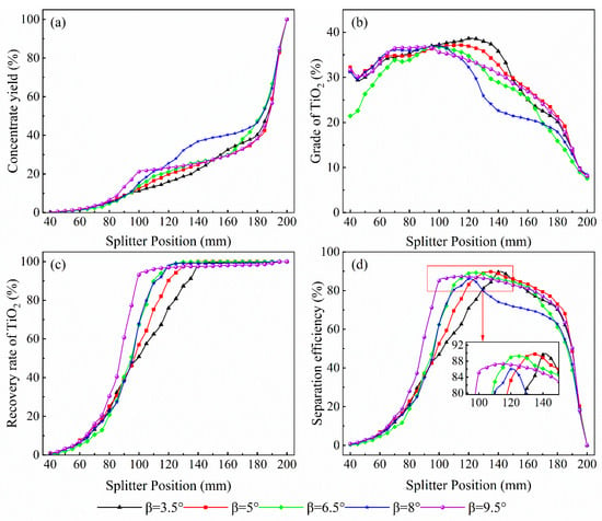
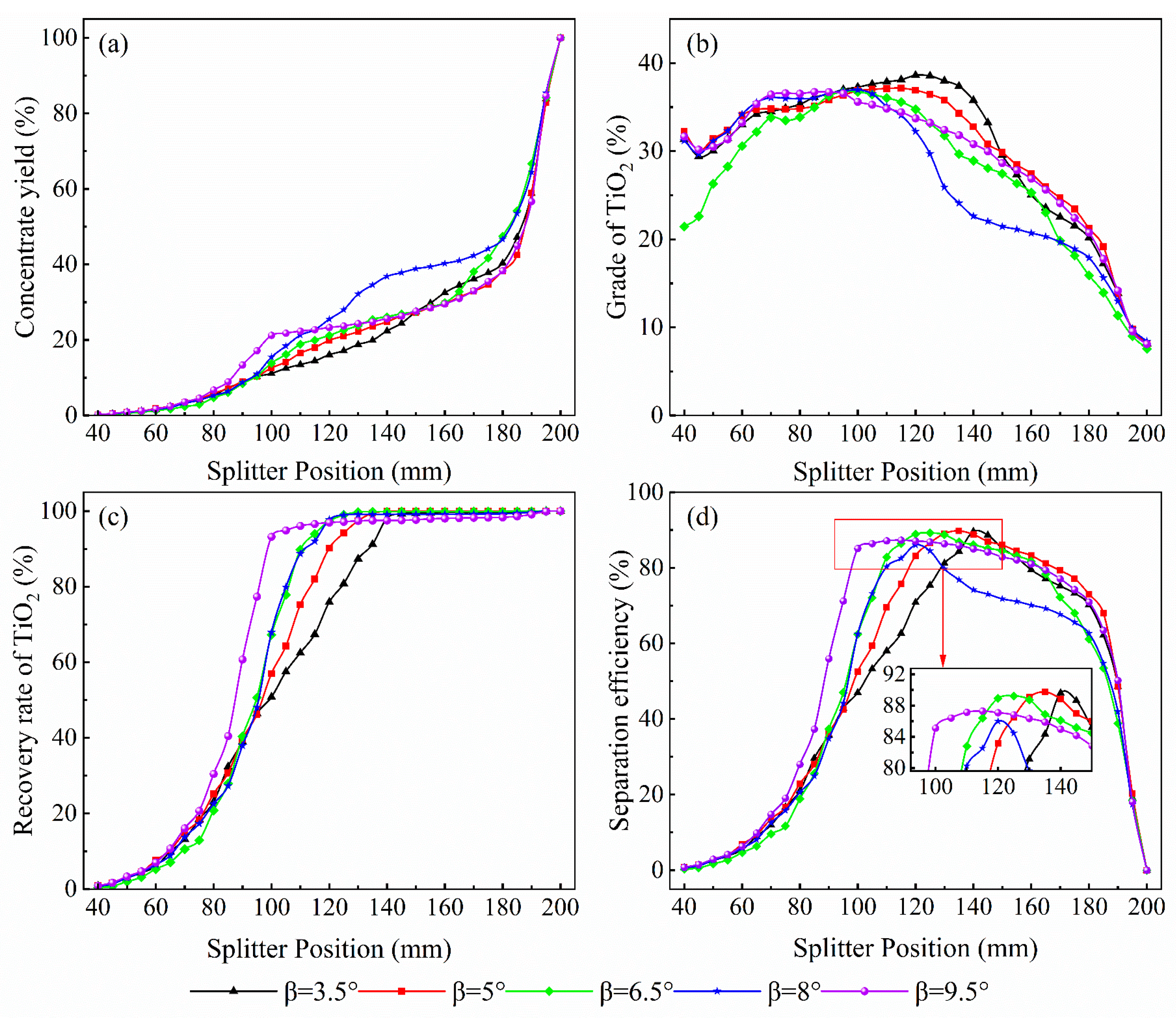
The concentrate yield, grade of TiO2, recovery of TiO2, and separation efficiency are important indicators for evaluating spiral separation performance, and the splitter position directly affects the product division and separation indicators [20,24]. Under different transverse inclination conditions, the splitter position in the trough of the third turn was adjusted to obtain multiple concentrate products. The results are shown in Figure 3.
Figure 3.
Particle-separation indicators at the end of the third trough under different transverse inclination angles of the middle trough: (a) concentrate yield; (b) grade of TiO2; (c) recovery rate of TiO2; (d) separation efficiency.
As shown in Figure 3, under different transverse inclination angles of the middle trough, concentrate yield increases to varying degrees as the splitter moves outward. The TiO2 grade first increases and then gradually decreases as the splitter moves outward. Under all conditions, a high-grade region is observed, and the concentrate grade is higher at relatively lower inclination angles (3.5° and 5°). TiO2 recovery increases significantly as the splitter moves outward, and the magnitude of the increase is positively correlated with the transverse inclination angle of the middle trough. The variation in separation efficiency is similar to that of grade, but the peak distribution is more pronounced, indicating the existence of a maximum separation efficiency and its corresponding optimal splitter position. To provide exact numerical values for the results shown in Figure 3, the key separation indicators corresponding to the maximum TiO2 grade of the concentrate and maximum separation efficiency are summarized in Table 2 and Table 3, respectively.
Table 2.
Maximum grade of TiO2 and corresponding splitter location and other indicators.
Table 3.
Maximum separation efficiency and corresponding splitter location and other indicators.
As shown in Table 2, increasing the transverse inclination angle of the middle trough causes the maximum TiO2 grade of the concentrate to decrease overall, and the corresponding splitter position shifts inward from 120 mm to 85 mm. When the transverse inclination increases from 3.5° to 5°, the maximum TiO2 grade of the concentrate decreases slightly, but concentrate yield, recovery of TiO2, and separation efficiency all improve, indicating excellent overall performance at low inclination angles. When the transverse inclination increases further beyond 5°, the TiO2 grade decreases slightly, while concentrate yield, recovery of TiO2, and separation efficiency decline markedly, especially when the angle increases from 8° to 9.5°.
As shown in Table 3, the maximum separation efficiency is more favorable in the range of 3.5–6.5°. Within this range, the optimal splitter position gradually moves inward from 140 mm to around 125 mm as the transverse inclination increases, with a corresponding decrease in the TiO2 grade of concentrate and little change in concentrate yield and recovery of TiO2. When the transverse inclination increases further beyond 6.5°, the maximum separation efficiency and recovery of TiO2 decrease to some extent, while concentrate yield and grade fluctuate, further indicating that a larger transverse inclination of the middle trough is unfavorable for separation of ilmenite and chlorite on the trough surface of the spiral concentrator.
As indicated by Table 2 and Table 3, a lower transverse inclination angle of the middle trough is more beneficial for improving the separation indicators of ilmenite and chlorite. When the objective is to maximize the TiO2 grade of the concentrate, the optimal inclinations are 3.5° and 5°, with splitter positions of 120 mm and 115 mm, respectively. This configuration achieves a high enrichment ratio while maintaining the other indicators. When the objective is to maximize separation efficiency, the optimal inclinations are 3.5°, 5°, and 6.5°, with splitter positions in the range of 140–125 mm. Under these conditions, both high concentrate quality and relatively stable yield and recovery can be maintained simultaneously. Therefore, the suitable ranges of middle-section transverse inclination and splitter position should be selected according to the specific separation objective.
3.1.2. Comparison of Separation Efficiency for Ilmenite–Chlorite Particle-Size Combinations
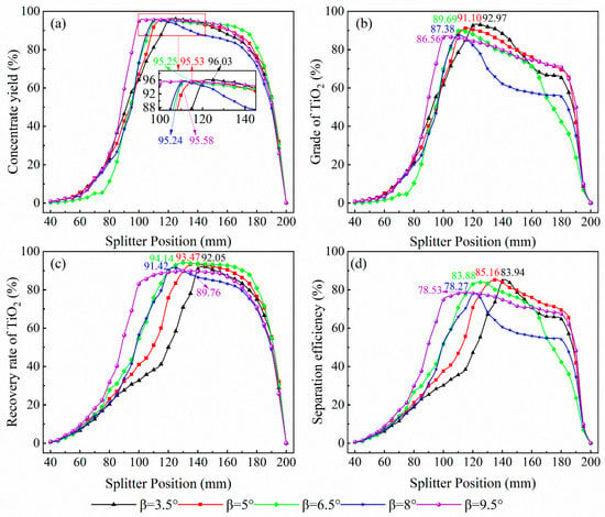
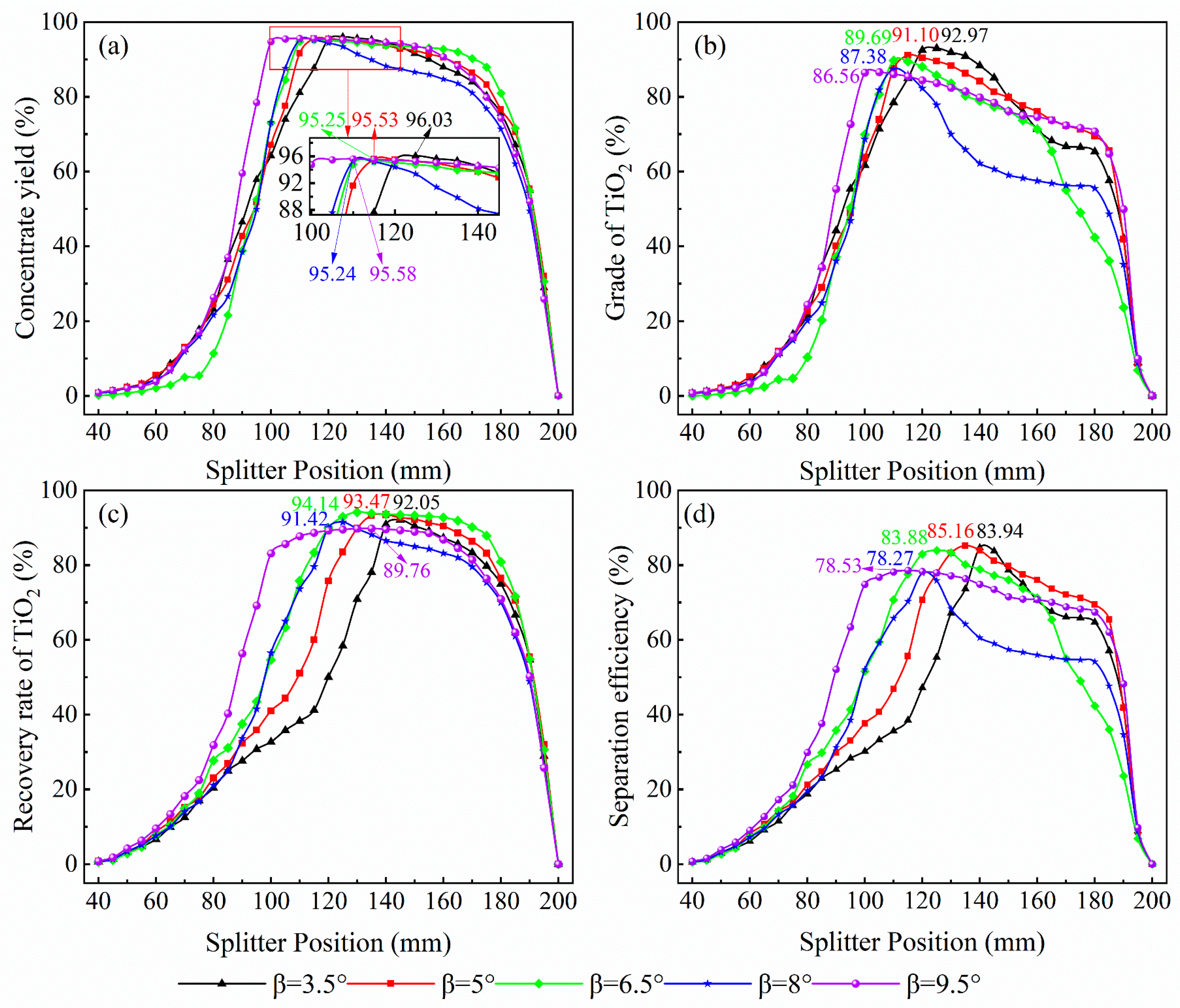
To further examine the effect of feed particle size on the separation result and the regulating role of the middle-section transverse inclination angle, ilmenite and chlorite particles of different sizes were combined in pairs as feedstock. The simulated data were extracted to obtain the separation-efficiency curves for the four feed systems under each transverse inclination angle, as shown in Figure 4.
Figure 4.
Variation in particle-separation efficiency with the transverse inclination angle of middle trough for different particle size combinations: (a) 112 μm ilmenite + 19 μm chlorite; (b) 112 μm ilmenite + 56 μm chlorite; (c) 56 μm ilmenite + 19 μm chlorite; (d) 56 μm ilmenite + 56 μm chlorite.
As shown in Figure 4, the separation efficiency of ilmenite–chlorite feed systems with different particle-size combinations differs significantly under different transverse inclination angles of the middle trough. Overall, the maximum separation efficiency achieved with a coarse-grained ilmenite feed system is higher than that achieved with a fine-grained ilmenite system. Furthermore, when the ilmenite size is fixed, the maximum separation efficiency is higher when the feed contains 19 μm chlorite. The comparative data are summarized in Table 4.
Table 4.
Change in maximum separation efficiency resulting from changes in feed particle size.
Table 4 clearly shows the differences in separation performance caused by variations in feed particle size, and the unfavorable effects of fine ilmenite and coarse chlorite appear to be additive.
As shown in Figure 4a,b, increasing the transverse inclination angle of the middle trough keeps the maximum separation efficiency of the coarse-ilmenite and fine-chlorite feed system between 95.24% and 96.03%, with the optimal splitter position shifting slightly inward. In contrast, the maximum separation efficiency of the coarse-ilmenite and coarse-chlorite system shows a decreasing trend. As shown in Figure 4c,d, the maximum separation efficiency of the fine-ilmenite and fine-chlorite system first increases slightly with increasing transverse inclination and then decreases, while the splitter position changes little. The maximum separation efficiency of the fine-ilmenite and coarse-chlorite system remains relatively high within the range of 3.5–6.5°and then decreases significantly.
The above analysis indicates that the coarse-ilmenite and fine-chlorite feed systems give the best separation performance and are relatively insensitive to changes in the middle-section transverse inclination angle. When the ilmenite size decreases or the chlorite size increases, the separation indicators decline and become much more strongly regulated by the middle-section transverse inclination angle, with an appropriate adjustment range of 3.5–6.5°. Therefore, the particle sizes of ilmenite and chlorite are clearly matched to the geometric parameters of the middle trough of the trough. Moreover, when feeding broad particle size, the mass fractions of fine ilmenite and coarse chlorite should be monitored and controlled to achieve stable improvement in separation performance.
3.2. Variation in Hydrodynamic Parameters of Slurry Flow with Adjustment of Middle-Section Transverse Inclination Angle
3.2.1. Depth Distribution of the Slurry Film and Longitudinal Difference
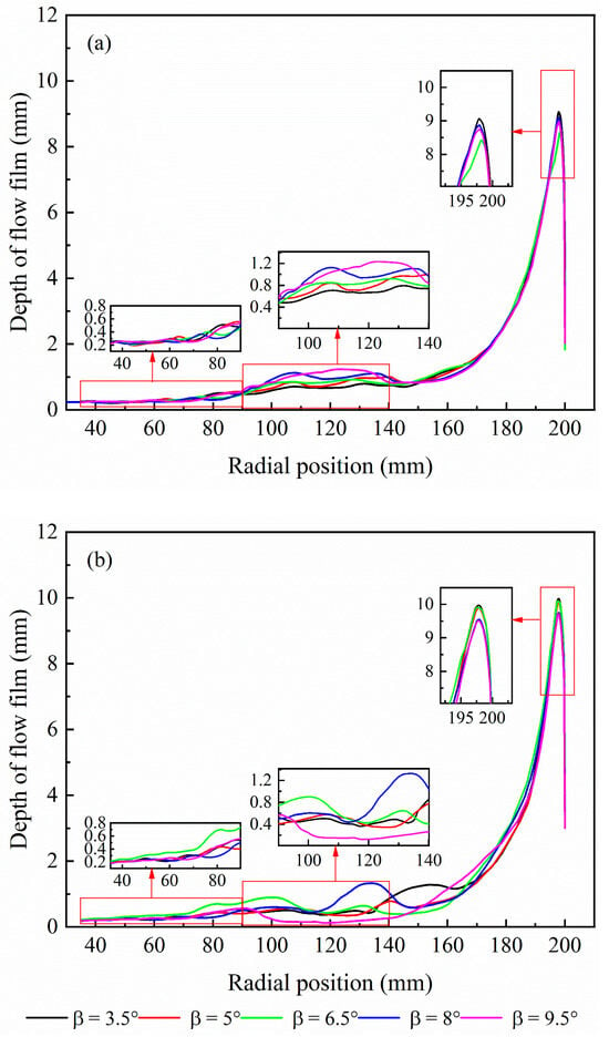
The depth of the slurry film determines the available separation space for mineral particles and affects the velocity distribution within the flow film [18,19]. Therefore, the flow film depths of ilmenite and chlorite slurries under different middle-section transverse inclination angles were extracted. The 1.5th turn and the third turn sections were selected to represent the separation process and the separation results, respectively, in order to examine the longitudinal differences in the depth distribution of the flow film. The results are shown in Figure 5.
Figure 5.
Film distribution of slurry on the trough surface under different transverse inclination angles of the middle trough: (a) the 1.5th turn; (b) the 3rd turn.
From both subfigures in Figure 5, the depth of the slurry flow film on the trough surface exhibits a pronounced radial distribution: the film thickness gradually increases with outward radial position. The maximum depth always concentrates at the outer edge, while the inner edge to middle radial region is dominated by a thin-film state, which is the core region for particle separation. Furthermore, the depth of the flow film in the inner edge and middle regions exhibits continuous fluctuations along the trough surface and differs from the near-bottom-wall film morphology of clear water.
As shown in Figure 5a and the local magnified view, in the trough surface of the 1.5th turn, the depth of the flow film in the middle thin-film region increases noticeably with increasing transverse inclination. At higher angles (8° and 9.5°), a clear bulge forms, whereas the deepest outer-edge film shows a dynamic response of first decreasing and then increasing. As shown in Figure 5b, when the slurry advances longitudinally to the end of the 3rd turn, the deepest outer-edge film becomes thicker compared to that at the 1.5th turn, while the middle flow film becomes thinner. This generally aligns with the hydrodynamic characteristics of longitudinal acceleration and contraction of the flow area. When the transverse inclination of the middle trough increases from 6.5° to 8° and 9.5°, the depth of the flow film at the deepest position decreases, and the middle flow film fluctuates strongly, especially at 9.5°. The depth distribution of the flow film in the middle region is clearly correlated with the separation indicators discussed above. Therefore, the suitable range of middle-section transverse inclination is identified as 3.5–6.5°, which is consistent with the range that yields favorable separation performance. This supports the validity of the numerical simulation and parameter characterization.
The above analysis indicates that, when the transverse inclination angle is 3.5° and 5°, the thin-film region on the trough surface forms a hydrodynamic environment with moderate thickness and stable distribution, which not only ensures adequate settling and enrichment of ilmenite particles but also effectively suppresses chlorite contamination of the concentrate zone. Meanwhile, the hydrodynamic environment in the deep-water region is favorable for chlorite to move toward the outer edge while avoiding excessive turbulence that would interfere with separation. This achieves a good match between the flow field distribution and the particle-separation behavior and provides stable hydrodynamic conditions for efficient ilmenite separation.
3.2.2. Spatial Distribution and Evolution of Secondary Circulation
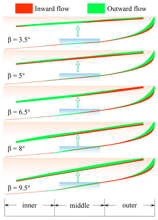
Under the ilmenite–chlorite feed system, this study investigated the effect of different middle-section transverse inclination angles on the spatial distribution of the secondary circulation and revealed its spatial distribution characteristics along the longitudinal travel, as shown in Figure 6.
Figure 6.
Spatial distribution of secondary circulation on the trough surface under different transverse inclination angles of the middle trough (the 1.5th turns).
As can be seen from the overall configuration of the secondary circulation in Figure 6, after evolving through 1.5 turns, the fluid has formed a basic secondary circulation structure in which the upper layer flows outward and the lower layer flows inward. Further analysis of the enlarged view of the secondary circulation in the middle region (95–140 mm) reveals that the spatial distribution and continuity of the inner and outer circulations differ markedly at different transverse inclination angles of the middle trough. Specifically, within the range of 3.5–6.5°, the inner circulation is continuously distributed in the middle and inner edge at 5° or is partially discontinuous at 3.5° and 6.5°, whereas the outer circulation maintains good continuity in both the middle and outer-edge regions. Within the range of 8–9.5°, the outer circulation in the middle and outer-edge regions is interrupted over a large area, which may hinder the transport of low-density particles, and the inner-circulation area is clearly reduced. Overall, when the transverse inclination angle of the middle trough is set to 5°, the secondary-circulation pattern across the spiral concentrator is the most stable and continuous, followed by angles of 5° and 6.5°.
3.2.3. Evolution of the Radial Flux of Secondary Circulation
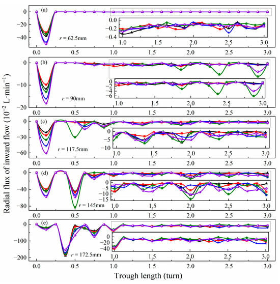
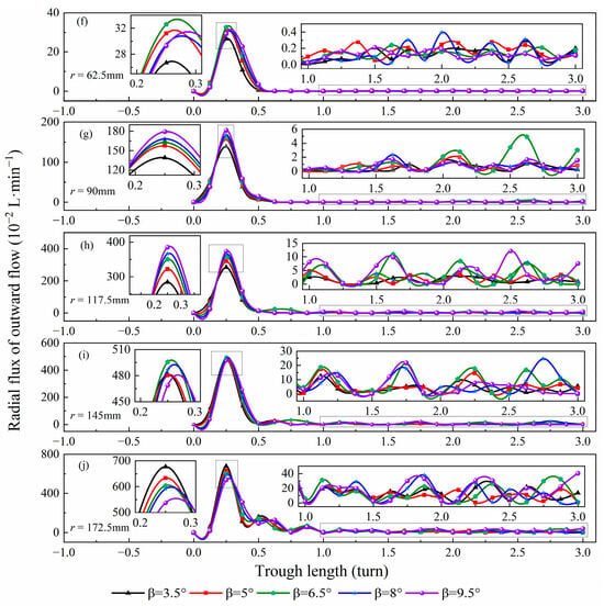
The variation in the radial flux of the secondary circulation with longitudinal travel can characterize the radial migration behavior of the fluid and its stability. The radial flux of the secondary circulation at different radial positions under adjustment of middle-section transverse inclination is shown in Figure 7.
Figure 7.
Evolution of radial flux of secondary circulation with longitudinal travel under different transverse inclination angles of the middle trough: (a–e) inward flow; (f–j) outward flow.
As shown in Figure 7, the radial flux of the secondary circulation evolves in a similar pattern with increasing longitudinal travel. It reaches a peak in the initial stage and then decreases and stabilizes within a specific range. The main difference is that the magnitude and fluctuation of radial flux increase as the radial position moves outward. The peak radial flux in the initial stage and the average radial flux in the stable stage at each radial position are listed in Table 5 and Table 6.
Table 5.
Peak radial flux (outside parentheses) in initial stage and average radial flux (inside parentheses) in stable stage (2.5–3 turns) of inner circulation/(10−2 L/min).
Table 6.
Peak radial flux (outside parentheses) in initial stage and average radial flux (inside parentheses) in stable stage (2.5–3 turns) of outer circulation/(10−2 L/min).
As shown in Table 5, when the transverse inclination angle of the middle-section trough increases from 3.5° to 9.5°, the peak radial flux of the inner circulation at r = 62.5 mm, 90 mm, and 145 mm first decreases and then increases, reaching a minimum value at 5°. At r = 117.5 mm, the peak value increases monotonically as the inclination increases. At the outer edge (r = 172.5 mm), the peak value decreases slightly at low angles and then rises markedly at medium and high angles. Overall, at medium and low inclination angles (3.5–6.5°), the peak radial flux of the inner circulation in the inner-edge and middle regions is lower than that at high inclination angles (8–9.5°). In the stable stage, the average radial flux of the inner circulation at each radial position generally increases in a fluctuating pattern with increasing inclination, indicating that a higher transverse inclination strengthens the radial transport of the inner circulation in the stable stage.
As shown in Table 6, at r = 90 mm and 117.5 mm, the peak radial flux of the outer circulation increases monotonically as the middle-section transverse inclination angle increases, demonstrating a clear positive correlation. In contrast, at the outer edge (r = 172.5 mm), the peak decreases monotonically as the inclination increases, from 677.25 × 10⁻² L/min to 537.95 × 10⁻² L/min, showing a clear negative correlation with the transverse inclination angle. At r = 62.5 mm and 145 mm, the peak radial flux of the outer circulation exhibits a fluctuating pattern, first increasing and then decreasing as the inclination angle increases. Furthermore, the average radial flux of the outer circulation in the stable stage at the middle region (117.5 mm) increases significantly at a high inclination angle (9.5°).
The variation trends of hydrodynamic parameters indicate that the middle-section transverse inclination angle exerts a significant zonal regulatory effect on the radial flux of the inner and outer circulations in different regions. At low inclination angles (3.5–5°), the peak radial flux of the inner circulation in the inner-edge and middle regions is relatively low, while the outer-edge region maintains a moderate flow field intensity. This distribution facilitates the stable enrichment of high-density ilmenite in the inner-edge and middle regions while effectively carrying low-density chlorite to the outer edge and reducing entrainment, thereby providing an ideal flow field environment for efficient mineral separation. Nevertheless, when the transverse inclination exceeds 6.5°, the radial flux of both the inner and outer circulations in the middle region together with the turbulence in the stable stage becomes stronger, which disrupts the original balanced flow field, interferes with ilmenite enrichment, and increases the risk of chlorite being carried inward, ultimately reducing separation stability and separation indicators.
3.3. Force Characteristics of Mineral Particles with Adjustment of Middle-Section Transverse Inclination Angle
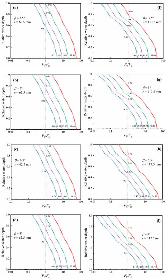
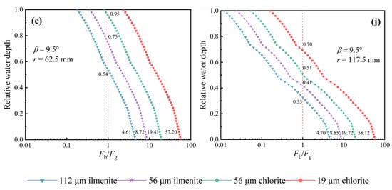
Given the key role of the spiral concentrator flow distribution and the flow field characteristics in the initial stage, two representative radial positions were selected at the inner edge (r = 62.5 mm) and the middle region (r = 117.5 mm) of the trough surface at the end of the 0.25th turn. Previous studies have incorporated the Bagnold effect into Eulerian multi-fluid VOF simulations to describe particle suspension, stratification, and migration behavior in the slurry flow within spirals [20,21]. Under different middle-section transverse inclination angles, the Bagnold force acting on ilmenite and chlorite particles was extracted and calculated. The distribution of the ratio |Fb/Fg| between the Bagnold force and the effective gravity along the relative depth of water was then examined, and the effect of the force characteristics on axial particle stratification and suspension was analyzed. The results are shown in Figure 8.
Figure 8.
Radial distribution characteristics of the ratio |Fb/Fg| along the relative water depth under different transverse inclination angles of the middle trough: (a) β = 3.5°, r = 62.5 mm; (b) β = 5°, r = 62.5 mm; (c) β = 6.5°, r = 62.5 mm; (d) β = 8°, r = 62.5 mm; (e) β = 9.5°, r = 62.5 mm; (f) β = 3.5°, r = 117.5 mm; (g) β = 5°, r = 117.5 mm; (h) β = 6.5°, r = 117.5 mm; (i) β = 8°, r = 117.5 mm; (j) β = 9.5°, r = 117.5 mm. The red dashed line indicates |Fb/Fg| = 1, where the Bagnold force equals the effective gravity.
As can be seen from the subfigures in Figure 8, as the relative water depth decreases, the dominant force acting on the particles shifts gradually from effective gravity to the Bagnold force. At the same relative water depth, the ratios |Fb/Fg| of the four types of particles are ranked in descending order as follows: 19 μm chlorite > 56 μm chlorite > 56 μm ilmenite > 112 μm ilmenite. This indicates that the Bagnold force acting on mineral particles is negatively correlated with both particle size and density and that particles with lower density and smaller size experience a more pronounced lift from the Bagnold force. In particular, for the fine-grained chlorite in the inner-edge flow field, the ratio of Bagnold force to effective gravity is significantly greater than 1, which promotes suspension in the upper layer of the film and transport by the outer circulation to the outside of the trough. Thereby, this explains why separation efficiency is higher when the feed size of chlorite is 19 μm.
In addition, the relative water depth at which particles in the middle region reach balance between Bagnold force and effective gravity (|Fb/Fg| = 1) is lower than that in the inner-edge region, indicating that the spatial gradient of Bagnold force acting on particles in the middle region is higher and has a greater influence on the separation process. As the transverse inclination angle of the middle trough increases, the balance positions of the axial forces acting on all four types of particles in the adjusted region shift downward, but the conditions for the extreme values of forces are different. Specifically, for coarse and fine ilmenite in the middle region, the ratio of Bagnold force to effective gravity at the bottom of the trough is lower under the two smaller inclination angles of 3.5° and 5° (coarse: 3.60 and 3.66; fine: 6.96 and 7.07) than that under the other three inclination angles. This enables particles to remain in the lower flow film and be transported inward by the inner circulation to the inner edge, thereby improving ilmenite enrichment. The ilmenite in the inner-edge region shows similar force magnitudes under different inclination angles, indicating that the separation process there is not affected by the transverse inclination angle of the middle trough. However, for both coarse and fine chlorite, the ratio of Bagnold force to effective gravity is higher under the three low-inclination angles of 3.5–6.5° (coarse: 19.99, 19.83, and 20.08; fine: 58.91, 58.46, and 59.19) than that under the other two angles, which is favorable for suspension into the upper outer circulation. This strengthens the outward transport tendency and reduces mixing with the ilmenite that has already been selectively enriched at the inner edge.
Overall, the middle-section transverse inclination angle has a pronounced effect on the Bagnold force acting on the particles, and the suitable inclination range for the axial separation process of mineral particles in this study can be optimized to 3.5–6.5°. Within this range, the Bagnold-force distributions of the middle-region ilmenite particles and the inner-edge chlorite particles are both well matched, allowing clear and stable axial stratification and thus yielding superior separation indicators. Therefore, using the ratio of Bagnold force to effective gravity as an indicator of particle-separation tendency is highly reliable.
4. Conclusions
- Adjusting the geometry of the middle trough of the spiral concentrator exerts a significant effect on the separation performance of feedings containing multi-sized ilmenite and chlorite. When a relatively small transverse inclination angle of 3.5–6.5° is adopted for the middle trough, excellent TiO2 enrichment performance and separation efficiency can be achieved. The suitable range for the splitter position should be reasonably selected according to the specific separation objective.
- The feed particle sizes of ilmenite and chlorite exert a remarkable effect on the separation performance in spirals and have an obvious matching relationship with the geometry of the middle trough. The separation performance of the feedings consisting of coarse-grained ilmenite (112 μm) or fine chlorite (19 μm) is optimal, with the maximum separation efficiency at approximately 95%. Separation indicators decline when fine-grained ilmenite (56 μm) and coarse chlorite (56 μm) are involved; nevertheless, adjusting the transverse inclination angle to the scope of 3.5–6.5° can sustain favorable separation performance for all feedings.
- When the section transverse inclination angle of the middle trough ranges from 3.5° to 6.5° (with 5° being the optimum), the film depth in the middle region is moderate. The continuity and stability of the inner and outer circulations over the entire trough surface reach the optimum. Meanwhile, the peak radial flux of the inner circulation at the inner and middle regions remains low, facilitating the construction of an ideal flow field for separation. Once the transverse inclination angle exceeds 6.5°, violent fluctuations occur in the flow film in the middle region, and the outward circulation suffers extensive disruption, exerting an adverse effect on particles separation.
- The mineral particles axial separation process in spirals can be reliably characterized by the ratio of Bagnold force to effective gravity (|Fb/Fg|). It is negatively correlated with particle density and size, and its spatial variation in the middle region is greater. When the transverse inclination angle is varying in the scope of 3.5–6.5°, ilmenite particles in the middle region can remain in the lower layer and be transported inward by the inner circulation for enrichment, and chlorite particles in the inner region can be suspended in the upper layer and be transported outward by outward circulation, so as to ensure effective axial stratification of mineral particles.
- The transverse inclination angle of the middle trough exerts a significant regulatory effect on the separation indicators of spirals. This effect is physically associated with the coupled evolution of flow film morphology, secondary circulation, radial flux, and particle force distribution, which collectively governs the settling and enrichment of ilmenite particles as well as the suspension and outward migration of chlorite particles. The variations in the flow field and particle force characteristics share the same underlying causes, thereby supporting the reliability of the numerical results and the suitability of the selected parameters for characterizing the separation process.
- At present, due to the limitations of the research period and the difficulty in manufacturing the prototype, no physical verification has been conducted for this study. Future work will focus on fabricating representative test prototypes and conducting physical verification experiments to further improve the reliability and accuracy of the numerical predictions.
Author Contributions
Conceptualization, S.G.; methodology, S.G., G.F. and D.T.; validation, X.Z. (Xiaohong Zhou), Q.W. and C.L.; data curation, Q.W.; formal analysis, Q.W. and C.L.; investigation, G.F. and D.T.; writing—original draft preparation, S.G. and X.Z. (Xintong Zhang); writing—review and editing, S.G. and X.Z. (Xintong Zhang); visualization, X.Z. (Xintong Zhang) and X.Z. (Xiaohong Zhou); supervision, S.G. All authors have read and agreed to the published version of the manuscript.
Funding
This research was funded by the Project of Zhongyuan Critical Metals Laboratory, grant number GJJSKFYB202406; and the National Natural Science Foundation of China, grant number 52274257.
Data Availability Statement
The original contributions presented in this study are included in the article. Further inquiries can be directed to the corresponding author.
Conflicts of Interest
The authors declare no conflicts of interest.
References
- Akhgar, B.N.; Pazouki, M.; Ranjbar, M.; Hosseinnia, A.; Salarian, R. Application of Taguchi method for optimization of synthetic rutile nano powder preparation from ilmenite concentrate. Chem. Eng. Res. Des. 2012, 90, 220–228. [Google Scholar] [CrossRef] [Scilit]
- Hasan, A.M.; Hossain, I.; Rahman, M.A.; Zaman, M.N.; Biswas, P.K.; Alam, M.S. Chemistry and mineralogy of Zr- and Ti-rich minerals sourced from Cox’s Bazar beach placer deposits, Bangladesh: Implication of resources processing and evaluation. Ore Geol. Rev. 2022, 141, 104687. [Google Scholar] [CrossRef] [Scilit]
- Kotova, B.; Ozhogina, G.; Ponaryadov, V. Technological mineralogy: Development of a comprehensive assessment of titanium ores, exemplified by the Pizhemskoye deposit. J. Min. Inst. 2022, 256, 632–641. [Google Scholar] [CrossRef] [Scilit]
- Lv, T.; Song, J.; An, Y.; Hu, T.; Lin, G.; Zhou, B. Efficient utilization of low-grade ilmenite: An innovative approach integrating pre-oxidation with CH4-H2 direct reduction for titanium carbide production. J. Environ. Chem. Eng. 2025, 13, 119103. [Google Scholar] [CrossRef] [Scilit]
- Yang, Y.; Hui, B.; Yan, S.; Chen, C.; Deng, J. Overview of global vanadium-titanium magnetite resources and comprehensive utilization. Multipurp. Util. Miner. Resour. 2023, 44, 1–11. [Google Scholar] [CrossRef]
- Yan, W. Study on new beneficiation technology for a refractory ultrafine ilmenite ore in Panxi. Nonferrous Met. Eng. 2020, 10, 76–82. [Google Scholar] [CrossRef]
- Sun, R.; Wang, Q.; Yuan, C.; Zhang, C.; Zhang, X.; Ba, T. Analysis of global titanium resources situation. China Min. Mag. 2019, 28, 1–6, 12. [Google Scholar] [CrossRef]
- Zhang, S.; Wen, S.; Liu, J.; Xian, Y.; Han, G.; Wang, Y. Research on mineral processing status of fine ilmenite. Conserv. Util. Miner. Resour. 2019, 39, 131–137. [Google Scholar] [CrossRef]
- Wang, F.; Cui, Y.; Tong, X.; Xie, X.; Meng, Q.; Deng, B. Research and application of beneficiation process for ilmenite. Multipurp. Util. Miner. Resour. 2016, 37, 1–6. [Google Scholar] [CrossRef]
- Xu, X.; Wang, F.; Zhang, C.; Xie, B.; Liang, T. Optimization of gravity separation flowsheet with spiral chute for collecting fine ilmenite. Min. Metall. Eng. 2021, 41, 45–48. [Google Scholar] [CrossRef]
- de Freitas Marques Araújo, P.; Silva, P.M.P.; do Carmo, A.L.V.; Gonçalves, M.V.L.; da Costa, R.V.; de Melo, C.C.A.; Lucheta, A.R.; Montini, M. Gravity Methods Applied to Bauxite Residue for Mineral Pre-concentration. In Light Metals 2021; Perander, L., Ed.; The Minerals, Metals & Materials Series; Springer: Cham, Switzerland, 2021. [Google Scholar] [CrossRef] [Scilit] [PubMed]
- Richards, R.G.; MacHunter, D.M.; Gates, P.J.; Palmer, M.K. Gravity separation of ultra-fine (−0.1 mm) minerals using spiral separators. Miner. Eng. 2000, 13, 65–77. [Google Scholar] [CrossRef] [Scilit]
- Liu, H.; Wu, H. Application and prospect of spiral concentrator. Nonferrous Met. (Miner. Process. Sect.) 2022, 5, 151–158. [Google Scholar] [CrossRef]
- Ye, G.; Ma, L.; Alberini, F.; Xu, Q.; Huang, G.; Yu, Y. Numerical studies of the effects of design parameters on flow fields in spiral concentrators. Int. J. Coal Prep. Util. 2022, 42, 67–81. [Google Scholar] [CrossRef] [Scilit]
- Sudikondala, P.; Mangadoddy, N.; Kumar, M.; Tripathy, S.K.; Yanamandra, R.M. CFD modelling of spiral concentrator: Prediction of comprehensive fluid flow field and particle segregation. Miner. Eng. 2022, 183, 107570. [Google Scholar] [CrossRef] [Scilit]
- Jain, P.K.; Rayasam, V. An analytical approach to explain the generation of secondary circulation in spiral concentrators. Powder Technol. 2017, 308, 165–177. [Google Scholar] [CrossRef] [Scilit]
- Ankireddy, P.R.; Purushotham, S.; Narasimha, M. Fluid flow modeling and analysis of low- and high-gravity spiral concentrators: Experimental and analytical approaches. Chem. Eng. Technol. 2023, 46, 1619–1629. [Google Scholar] [CrossRef] [Scilit]
- Gao, S.; Liu, C.; Zhou, X.; Zhang, X.; Wang, Q.; Han, C. Influence of cross-sectional curve equation on flow field evolution and particle separation in the spiral concentrator of the first turn. Separations 2025, 12, 327. [Google Scholar] [CrossRef] [Scilit]
- Zhou, X.H.; Gao, S.L.; Meng, L.G.; Zhao, Q. Influence of wall roughness on slurry flow and particles separation behaviors in spirals. J. Northeast. Univ. (Nat. Sci.) 2023, 44, 1769–1777. [Google Scholar] [CrossRef]
- Gao, S.; Meng, L.; Zhou, X.; Shen, Y.; Cui, B.; Song, Z. Design of partial cross-sectional geometry and prediction of separation performance in the spiral separator. Sep. Sci. Technol. 2022, 57, 2127–2144. [Google Scholar] [CrossRef] [Scilit]
- Meng, L.; Gao, S.; Wei, D.; Zhao, Q.; Cui, B.; Shen, Y.; Song, Z. Particulate flow modelling in a spiral separator by using the Eulerian multi-fluid VOF approach. Int. J. Min. Sci. Technol. 2023, 33, 251–263. [Google Scholar] [CrossRef] [Scilit]
- Wang, J.H.; Luo, J.; Huang, S.X.; Xia, J.; Yang, B.; Wang, Y. Numerical simulation of single aluminum droplet evaporation based on VOF method. Case Stud. Therm. Eng. 2022, 34, 102008. [Google Scholar] [CrossRef] [Scilit]
- Doheim, M.A.; Gawad, A.A.; Mahran, G.M.A.; Abu-Ali, M.H.; Rizk, A.M. Numerical simulation of particulate-flow in spiral separators: Part I. Low solids concentration (0.3% and 3% solids). Appl. Math. Model. 2013, 37, 198–215. [Google Scholar] [CrossRef] [Scilit]
- Gao, S.; Meng, L.; Wei, D.; Song, Z.; Yuan, J. Study on distribution characteristics of secondary circulation in spirals based on CFD. China Min. Mag. 2020, 29, 139–146. [Google Scholar] [CrossRef]
- Gao, S.; Meng, L.; Wei, D.; Zhao, Q.; Cui, B.; Zhou, X. A Prediction and Optimization Method for Separation Indicators of Mineral Particles in the Flow Film of Spiral Concentrator. Chinese Patent CN115270587B, 9 June 2023. [Google Scholar]

Disclaimer/Publisher’s Note: The statements, opinions and data contained in all publications are solely those of the individual author(s) and contributor(s) and not of MDPI and/or the editor(s). MDPI and/or the editor(s) disclaim responsibility for any injury to people or property resulting from any ideas, methods, instructions or products referred to in the content. |
© 2026 by the authors. Licensee MDPI, Basel, Switzerland. This article is an open access article distributed under the terms and conditions of the Creative Commons Attribution (CC BY) license.