


Abstract
Fully mechanized coal mining is a key method of coal extraction. As mining intensity increases, dust pollution in fully mechanized mining faces has become increasingly severe, significantly hindering the coal industry‘s alignment with the “Healthy China” strategy. To address the prominent dust pollution and the inefficiency of current spray dust suppression methods, this study proposes a combined spray dust suppression system. Using the Taigemiao mining area—where the coal dust exhibits hydrophilic characteristics—as a case study, we investigate the system’s spray flow field characteristics via numerical simulation. The results indicate that activating the shearer‘s external nozzles increases the airflow velocity near the shearer to 4 m/s, with the droplet concentration at the breathing zone height peaking at 28,786 mg/m3. Furthermore, activating the inter-support spray-induced dust removal device boosts the airflow velocity to 15.8 m/s, generating negative pressure at the dust suction inlet and forming a high-concentration droplet zone near the coal wall. During the operation of the combined system, the droplet distribution is characterized by “three high-concentration areas” and “post-nozzle attenuation.” The optimal droplet proportion reaches 93.81%, maintaining an appropriate velocity within the efficient dust capture range. Overall, the dust capture efficiency of the combined system is significantly superior to that of a single spray system.
1. Introduction
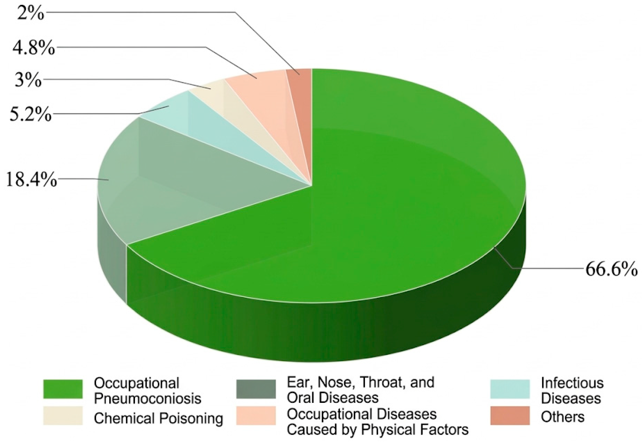
With the continuous growth of coal demand in China, coal production has entered the deep mining stage [1,2]. More and more intelligent equipment has been adopted in the production of fully mechanized mining faces, which has significantly improved production efficiency. However, this has also made the problem of dust pollution more serious [3,4,5], becoming a key hidden danger affecting the occupational health of employees and the safe production of mines [6,7]. In 2023, occupational pneumoconiosis accounted for 66.6% of all confirmed occupational diseases in China. Among these pneumoconiosis cases, the vast majority originated from the coal mining industry. Moreover, the majority of these cases were from coal miners, as shown in Figure 1. However, the dust removal measures currently adopted have limited dust suppression effects, and the dust concentration in fully mechanized mining faces often exceeds the safety standards. Therefore, it is urgently necessary to optimize the current dust-proof technology [8].
Figure 1.
Percentage of occupational diseases in China, 2023.
Spray dust suppression technology is a key measure for dust control in coal mines [9]. Atomizing nozzles are installed at dust-generating points to create a water mist barrier that prevents dust dispersion. In fully mechanized mining faces, this technology is primarily applied to shearer operation zones and hydraulic support advancement areas.
Regarding shearer operations, Aziz et al. [10] combined a shearer cleaning cover with Venturi and fan-shaped nozzles, integrating physical isolation with spray dust suppression to achieve full mist coverage of the shearer drum area. Ren et al. [11] designed a dust-blocking system consisting of an intake hood, a hydraulic fan, and an exhaust pipe located at the connection between the shearer’s rocker arm and body. The negative pressure airflow generated by the hydraulic fan intercepted most of the dust within the dense spray zone, while simultaneously forming an air curtain to concentrate the remaining dust towards the center, achieving an overall dust suppression efficiency of 76%. Furthermore, Parra et al. [12] installed a dual-nozzle spray device on top of the shearer. As the shearer cuts coal and advances, it forms a dynamic water curtain barrier. This device effectively captures fine particles ranging from 5 to 20 μm; it not only wets the coal surface but also facilitates collisions between spray droplets and dust particles, accelerating dust sedimentation.
In the context of dust control for hydraulic support relocation, Nie et al. [13] proposed an inter-support spray-induced dust removal technology. By comparing 12 nozzle types, they determined that a pressure of 8 MPa yielded the optimal efficiency for suppressing respirable dust. Wang et al. [14] further optimized this system by adjusting nozzle spacing and spray angles, effectively covering primary dust diffusion zones in field applications. Expanding on these specialized studies, Hu et al. optimized tracking spray nozzles to specifically address the challenges of large mining heights [15], while Jing et al. investigated broader dust migration laws to develop integrated spray technologies for comprehensive mining faces [16]. These advancements underscore the necessity of a coordinated, multi-zonal spray system.
Despite these advancements, current dust control technologies primarily focus on isolated processes—such as individual shearer or hydraulic support spraying—and lack an optimized, comprehensive design for the entire fully mechanized mining face. Therefore, to further enhance system efficiency, this study designs a combined spray dust suppression system based on the Taigemiao fully mechanized mining face. The spray flow field characteristics of this combined system are investigated using numerical simulations, providing a theoretical basis and technical reference for on-site applications.
2. Combined Spray Dust Suppression Technology Method
The Taigemiao mining area employs a retreat longwall fully mechanized mining method, utilizing the full caving method for roof management. Under these conditions, the cutting action of the shearer and the advancement of the hydraulic supports constitute the primary dust sources at the working face [17]. To achieve effective dust control, a combined spray dust suppression system was designed, guided by the principles of “source suppression, zonal control, and system coordination.”
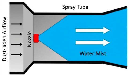
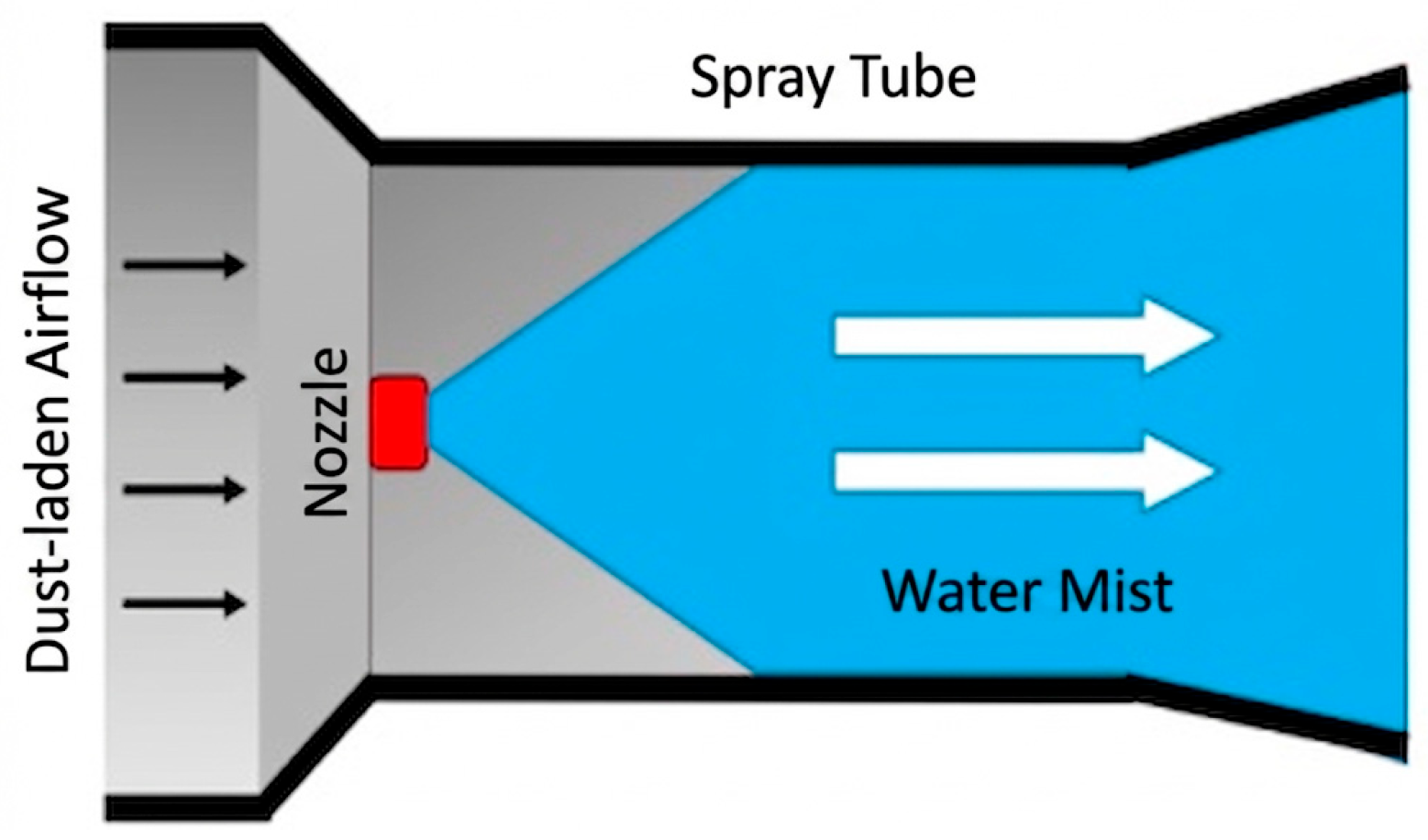
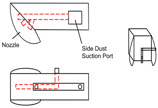
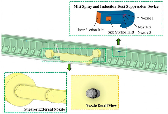
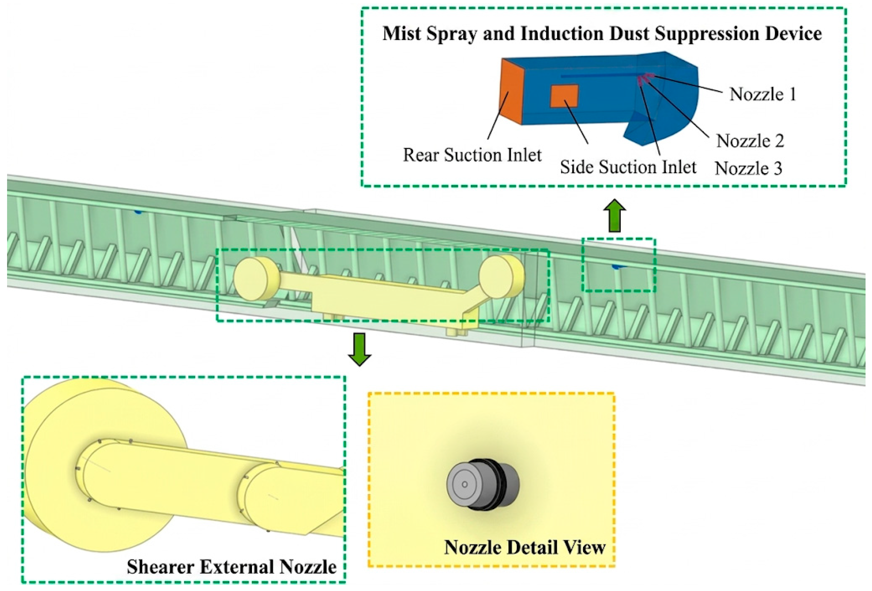
As observed in Figure 2 and Figure 3, for shearer dust suppression, a precise external spray configuration was developed based on the dust generation characteristics of the cutting drum. Four B2# nozzles are arranged in a circular array around the shearer casing. Their installation angles span from −90° to 90° on the horizontal plane of the ranging arm, with a 30° inclination toward the coal wall. Additionally, five nozzle groups are evenly distributed in a circular pattern on both the front and rear ranging arm boxes. These installation angles cover a full −180° to 180° on the horizontal plane, with the axis of each nozzle positioned perpendicular to the longitudinal centerline of the ranging arm. This configuration utilizes a total of 18 external nozzles to form a dual-layer spray structure—comprising “motor housing nozzles” and “ranging arm nozzles”—achieving 360° full coverage of the dust sources generated by the shearer drum.
Figure 2.
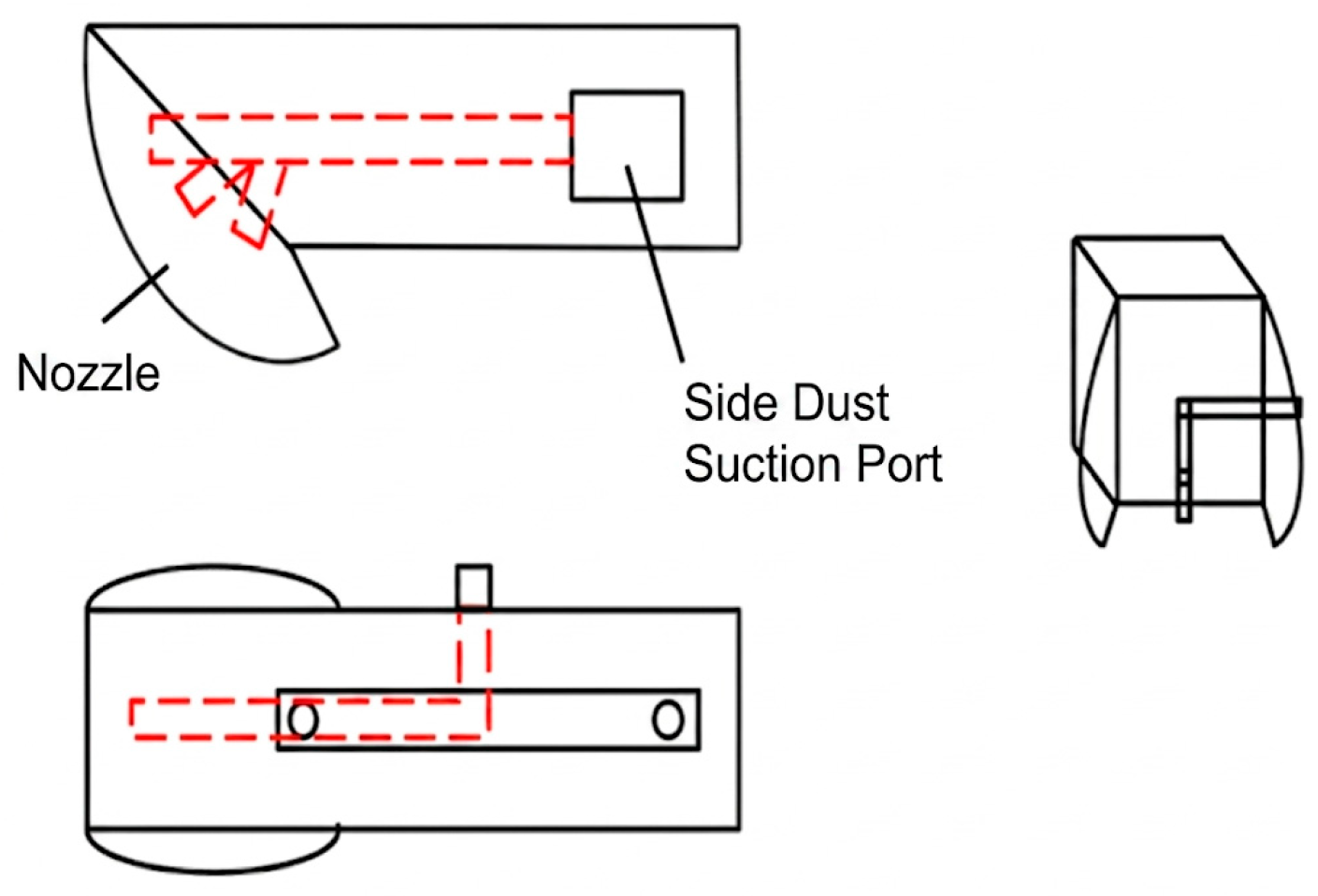
Schematic diagram of negative pressure elicitation mechanism.
Figure 3.
Schematic diagram of a spray-induced dust removal device.
In the hydraulic support zone, an inter-support spray-induced dust removal device based on the Venturi principle is implemented [18]. This device is internally equipped with three nozzles oriented at angles of 15°, 45°, and 75° relative to the horizontal direction. It features two suction inlets: a 100 mm × 80 mm rectangular port on the side and a 200 mm square port at the rear. By leveraging the negative pressure generated by the high-speed water flow at the throat, the device not only enhances atomization but also actively draws in the dust-laden airflow. The selected B2# nozzle [19,20] operates with a 120° atomization angle at a working pressure of 8 Mpa. Crucially, its droplet size distribution aligns perfectly with the particle size characteristics of the dust at the working face, providing the necessary conditions for highly efficient dust capture.
3. Numerical Simulation Research on the Spray Dust Suppression System
3.1. Construction and Simulation Scheme of a Spray Model for a Fully Mechanized Coal Mining Face
The geometric model of the fully mechanized mining face has dimensions of 350 m in length, 5.0 m in width, and 4.0 m in height. The model is divided into three sections: the 0–24 m section represents the completed support advancement area, the 24–60 m section is the active coal cutting area, and the 60–350 m section corresponds to the unmined area. An MG500/1130-WD double-drum shearer and ZY21000/36.5/80D shield hydraulic support, produced by China Coal Technology & Engineering Group (Beijing, China), are employed in this model The external nozzles of the shearer and the inter-support spray-induced dust removal devices collectively constitute the spray dust suppression system of the working face (Figure 4).
Figure 4.
Model diagram of spraying and de-dusting system for the synthesized mining face.
The boundary conditions of the model are established accordingly, with the parameter settings for the discrete phase (spray) detailed in Table 1.
Table 1.
Spraying parameter settings.
For the numerical simulation, a transient solver is applied, utilizing the highly accurate Realizable k-ε model for turbulence simulation. Furthermore, the Taylor Analogy Breakup (TAB) model is employed to simulate droplet breakup, and the SIMPLE algorithm is selected for pressure–velocity coupling calculations. This study simulates the dust suppression characteristics under three distinct operating conditions: (1) activating only the shearer’s external spray system; (2) activating only the inter-support spray device in the support advancement area; and (3) simultaneously activating both the shearer and inter-support spray systems. The simulation results are subsequently analyzed to evaluate the dust distribution patterns and suppression efficacy under each condition.
3.2. Mesh Independence Verification
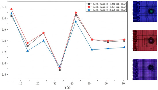
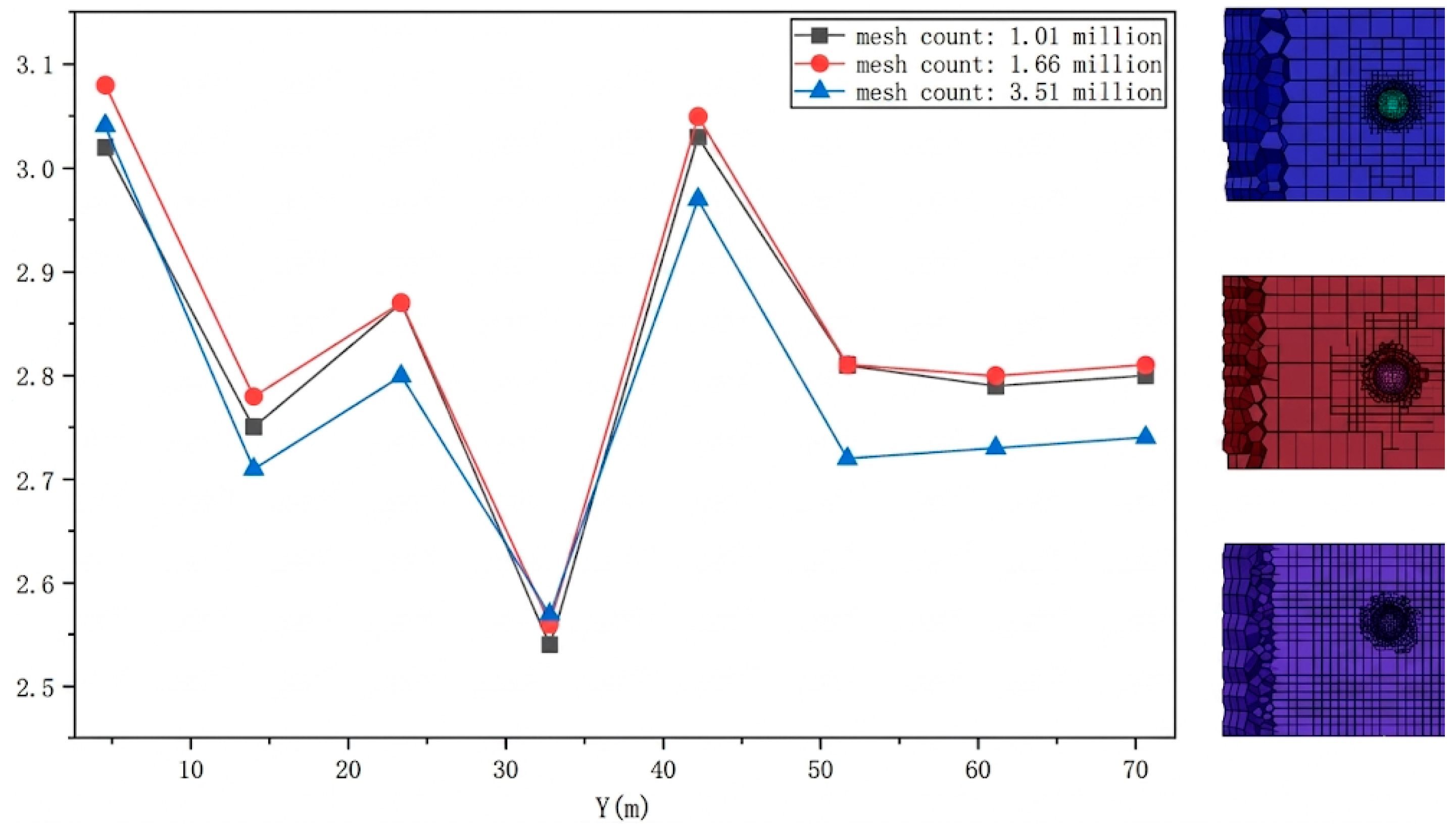
To ensure numerical accuracy and eliminate grid-induced errors, a grid independence test was conducted using mesh schemes of 1.01 million, 1.66 million, and 3.54 million cells. Under a consistent ventilation velocity of 2.5 m/s, airflow velocity monitoring along the Y-axis demonstrated that while the 1.01 million mesh exhibited visible deviations, the results for the 1.66 million and 3.54 million meshes were highly consistent with negligible relative error (Figure 5). Consequently, the 1.66 million mesh was selected for subsequent simulations to balance computational precision and efficiency.
Figure 5.
Grid independence verification of the airflow velocity at a ventilation speed of 2.5 m/s.
3.3. Analysis of Simulation Results of Spray Outside the Coal Shearer
The primary function of the shearer’s external spray system is to form a droplet barrier at the dust generation source during drum cutting. By altering the local airflow direction and increasing the droplet concentration, it facilitates the immediate capture of airborne dust. This section evaluates the system’s dust suppression efficacy by simulating and analyzing the airflow distribution, droplet spatial distribution, and concentration profiles before and after system activation.
3.3.1. Airflow Distribution Characteristics
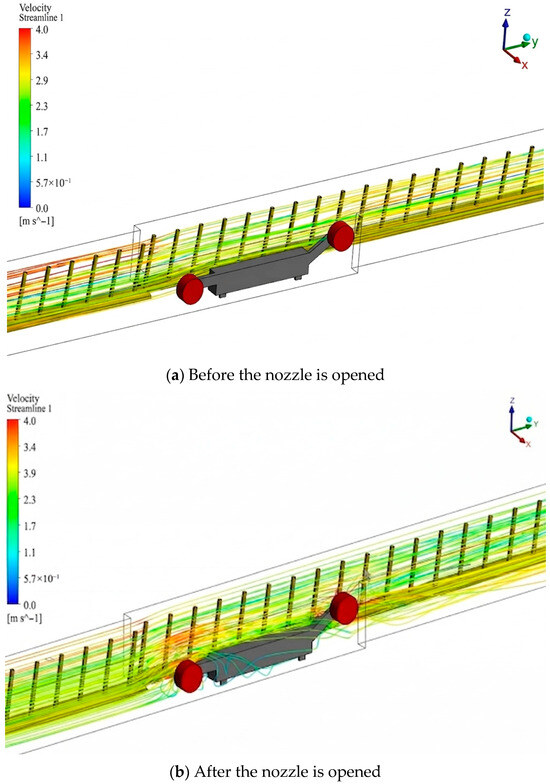
The simulation data were imported into CFD-Post for visualization, generating the airflow streamlines around the shearer both before and after the activation of the external spray system.
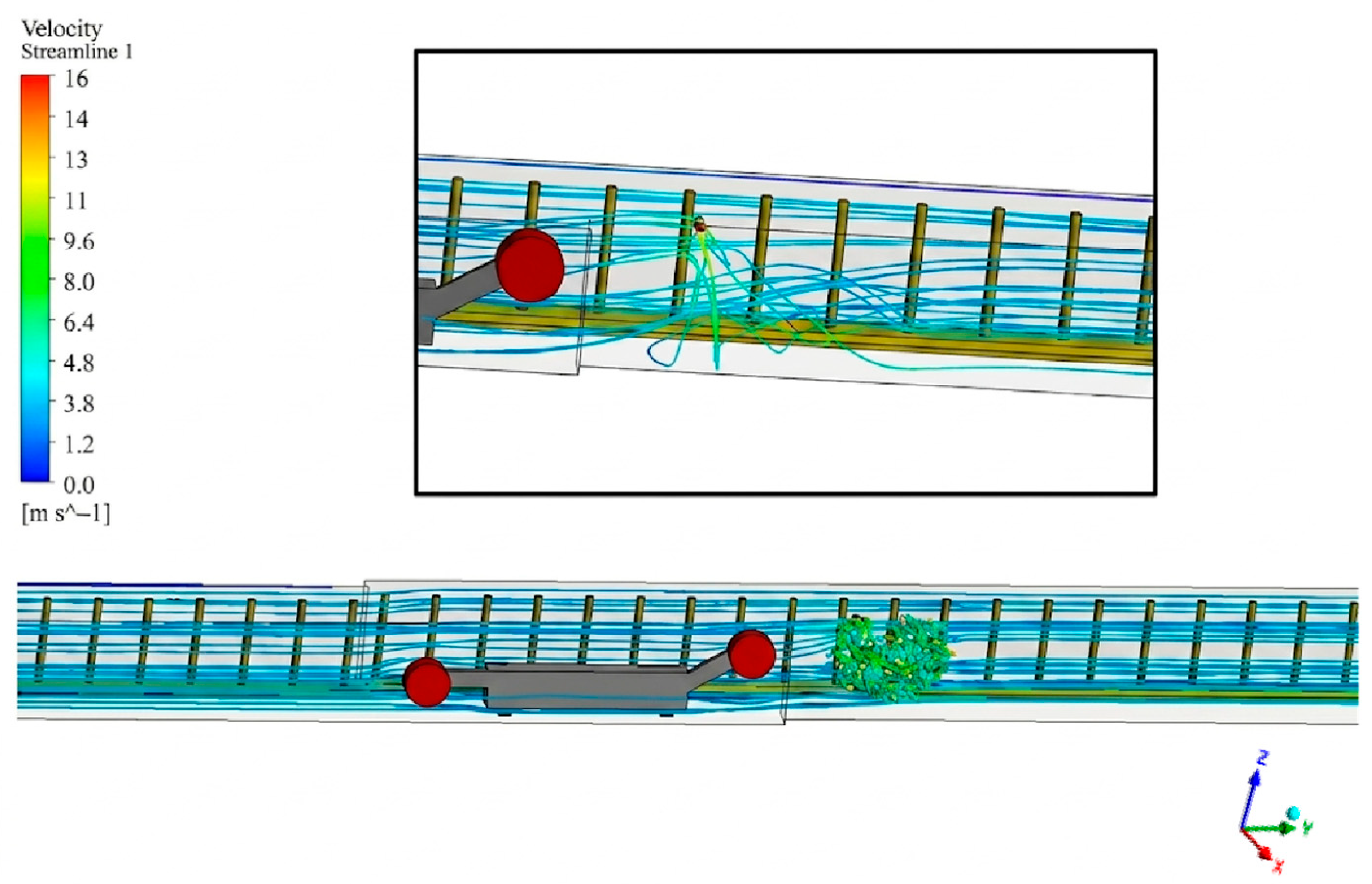
As observed in Figure 6, following the activation of the nozzles, the airflow streamlines around the front and rear drums of the shearer become highly turbulent, with the airflow diverting toward the spray direction. Based on fluid mechanics principles, the high-speed jets emitted from the shearer’s external nozzles entrain the surrounding air, creating a localized low-pressure zone. This effect alters the primary airflow direction and forces the dust-laden airflow toward the coal wall. Consequently, a “dust-airflow isolation barrier” is formed, effectively mitigating the dispersion of dust into the walkways and the shearer operator’s position.
Figure 6.
Trace of wind flow in the vicinity of the coal miner.
Furthermore, the local airflow velocity near both drums increases to 4 m/s. This acceleration occurs because the high-velocity, high-pressure spray jets superimpose their kinetic energy onto the primary ventilation airflow of the working face. This localized increase in airflow velocity around the drums significantly enhances the collision and agglomeration rates between dust particles and water droplets.
3.3.2. The Distribution Pattern of Droplet Particles
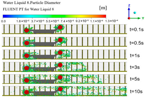
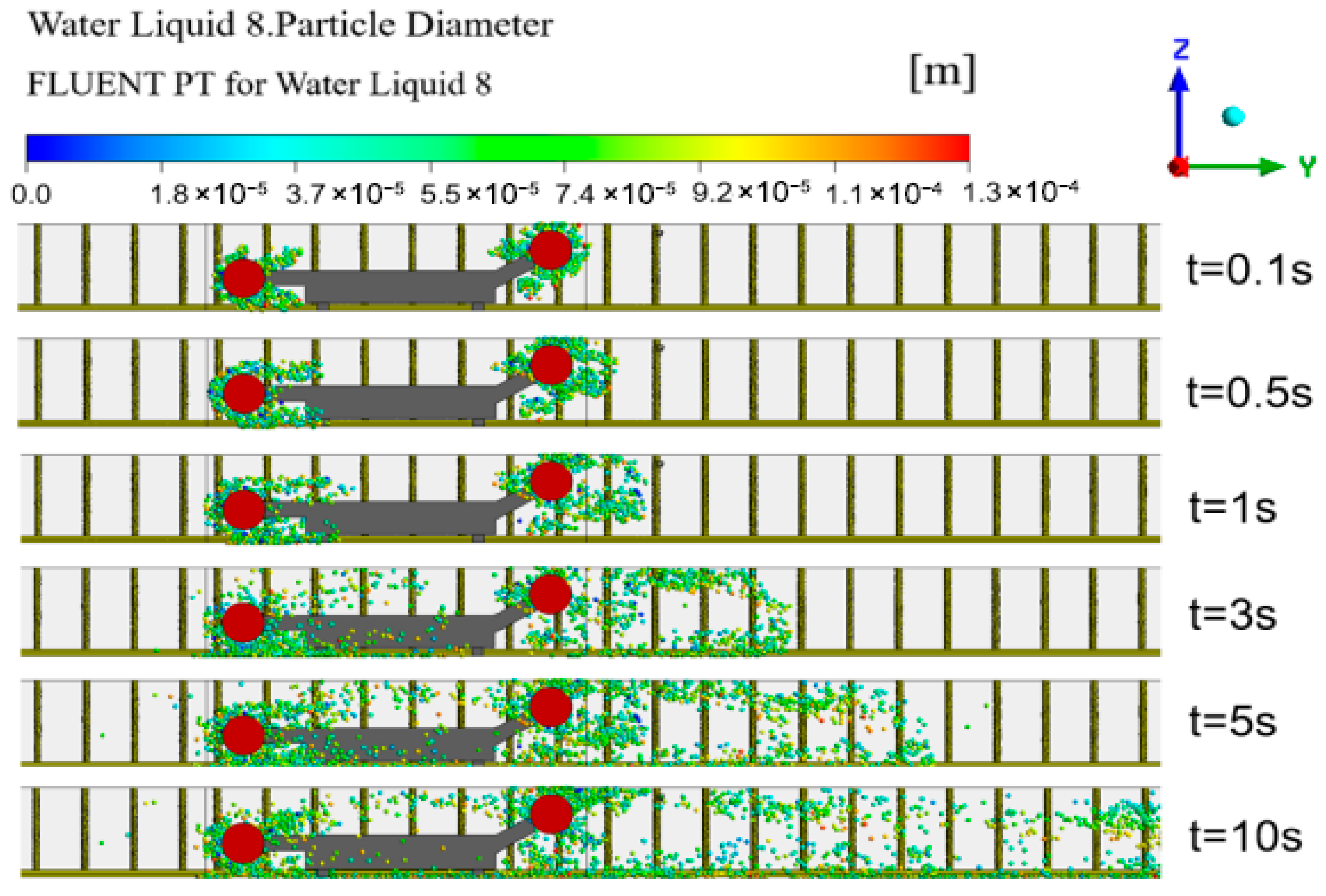
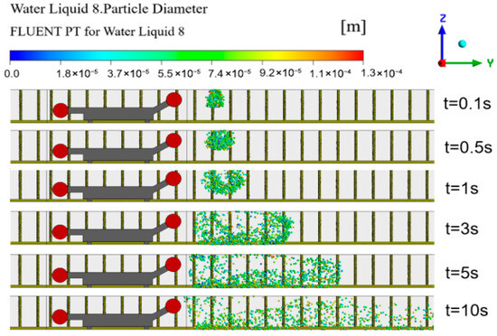
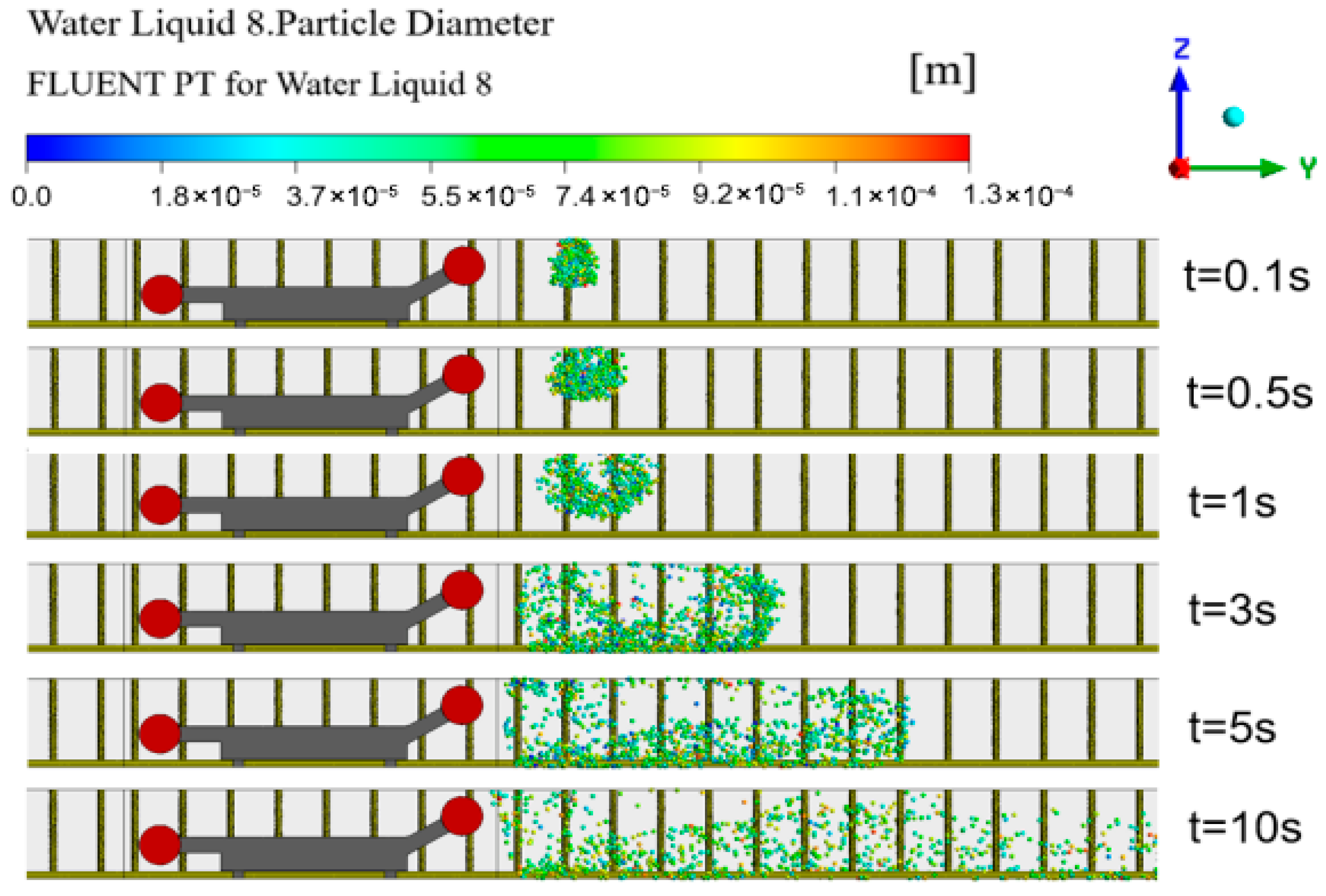
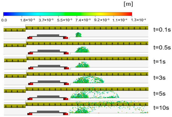
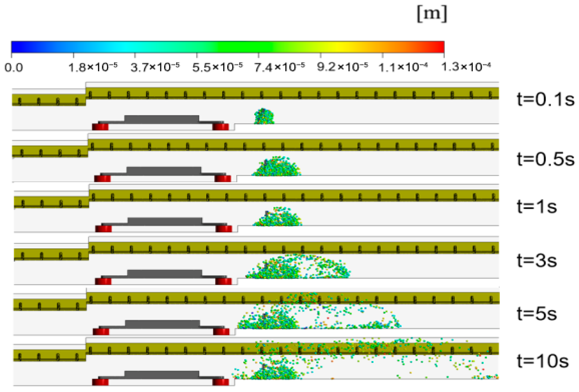
To analyze the diffusion and sedimentation characteristics of droplets at different times, a spherical particle model was selected in CFD-Post, and the particle distribution trajectories at t = 0.1 s, t = 0.55 s, t = 1 s, t = 3 s, t = 5 s and t = 10 s were observed.
Figure 7 illustrates the vertical diffusion and sedimentation of droplets. In the early stage (t ≤ 1 s), the droplets form a concentrated cluster near the nozzle height, with particle sizes mainly distributed around 70 μm. At this stage, the vertical displacement is minimal as the droplets are primarily driven by the initial spray momentum and airflow. By t = 5 s, the influence of gravity becomes prominent; larger droplets begin to deviate from the air streamlines and settle toward the floor. At t = 10 s, the front view reveals a clear vertical stratification: a significant portion of droplets has settled to the ground, while finer particles remain suspended at the breathing zone, continuing to migrate downwind.
Figure 7.
Front view of the position of spray droplets outside the coal miner at different times.
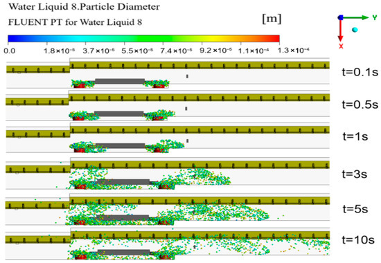
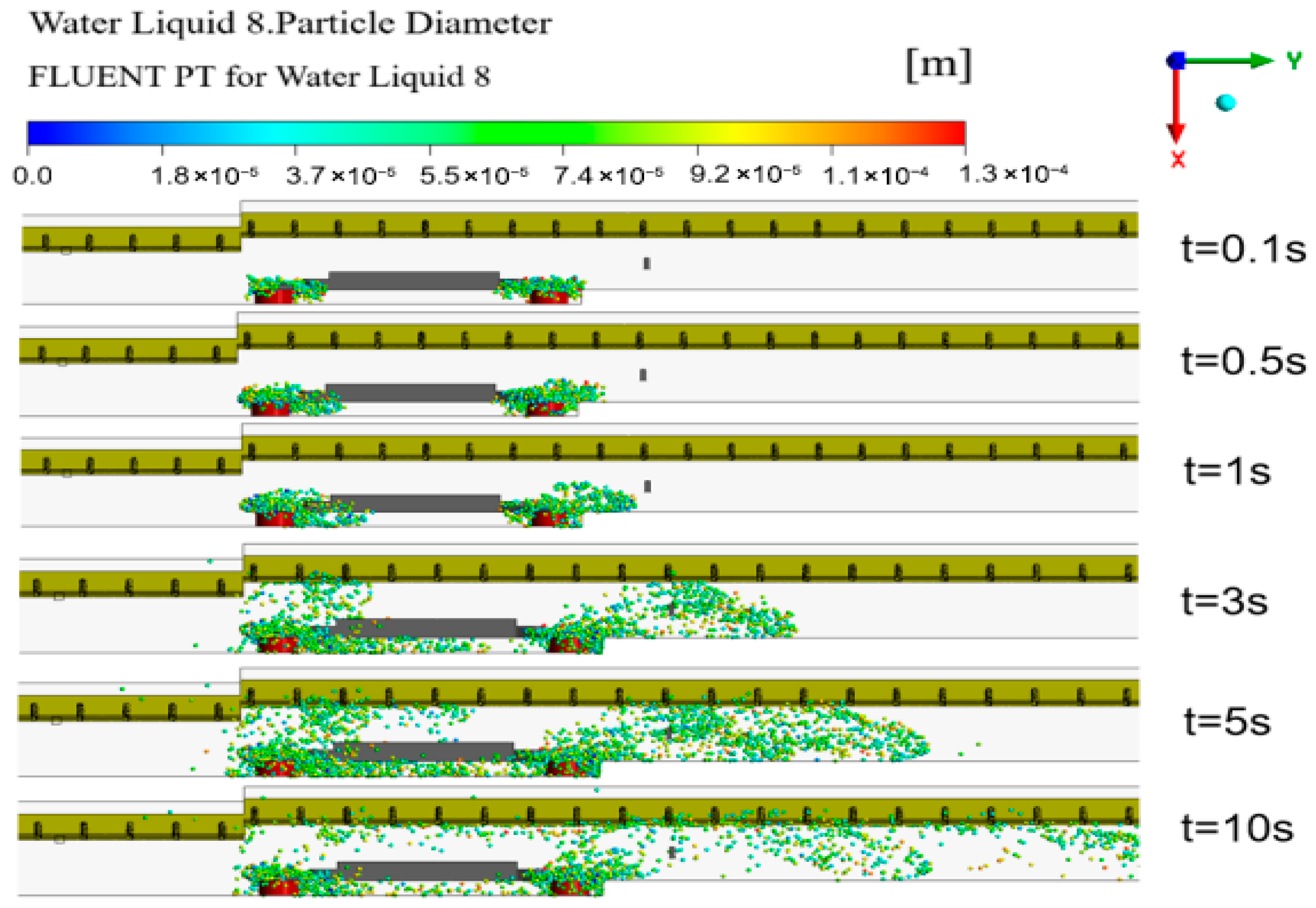
Figure 8 provides a top-down perspective of the horizontal spray evolution. Within 1 s, the spray maintains a narrow expansion width, concentrated near the coal shearer body. As time progresses to 5 s, the mist expands laterally, covering a width of approximately 10 m and enveloping the drum area. By 10 s, the horizontal diffusion range extends beyond 20 m, showing the droplets’ ability to bypass the shearer body and disperse into the downwind walkway. This top view highlights the coverage efficiency of the spray system across the entire working face width.
Figure 8.
Top view of the position of spray droplets outside the coal miner at different times.
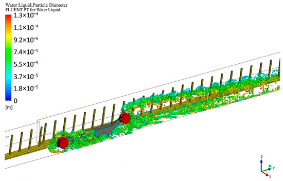
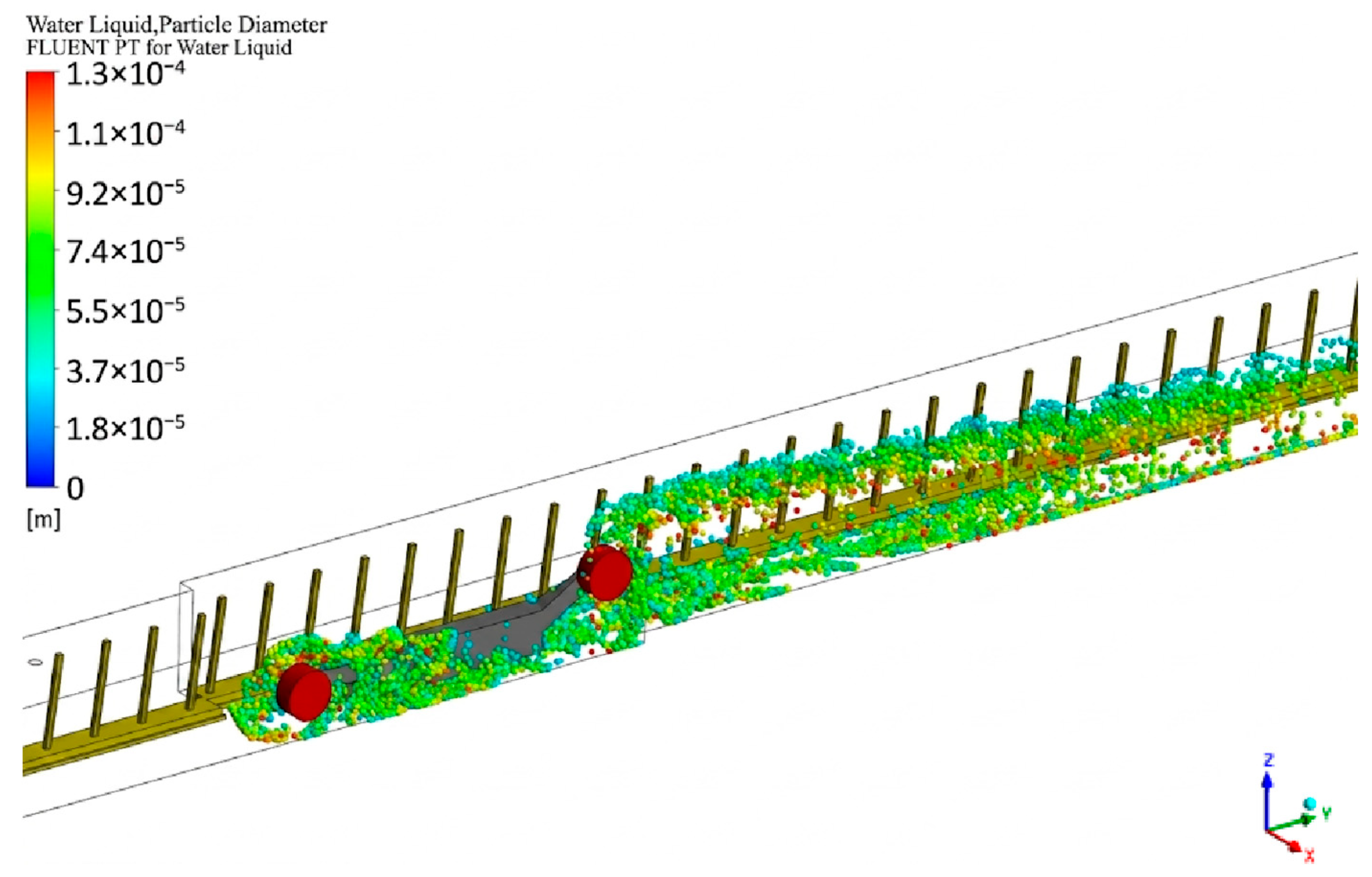
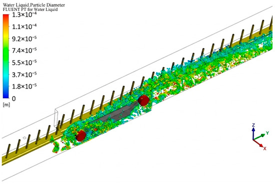
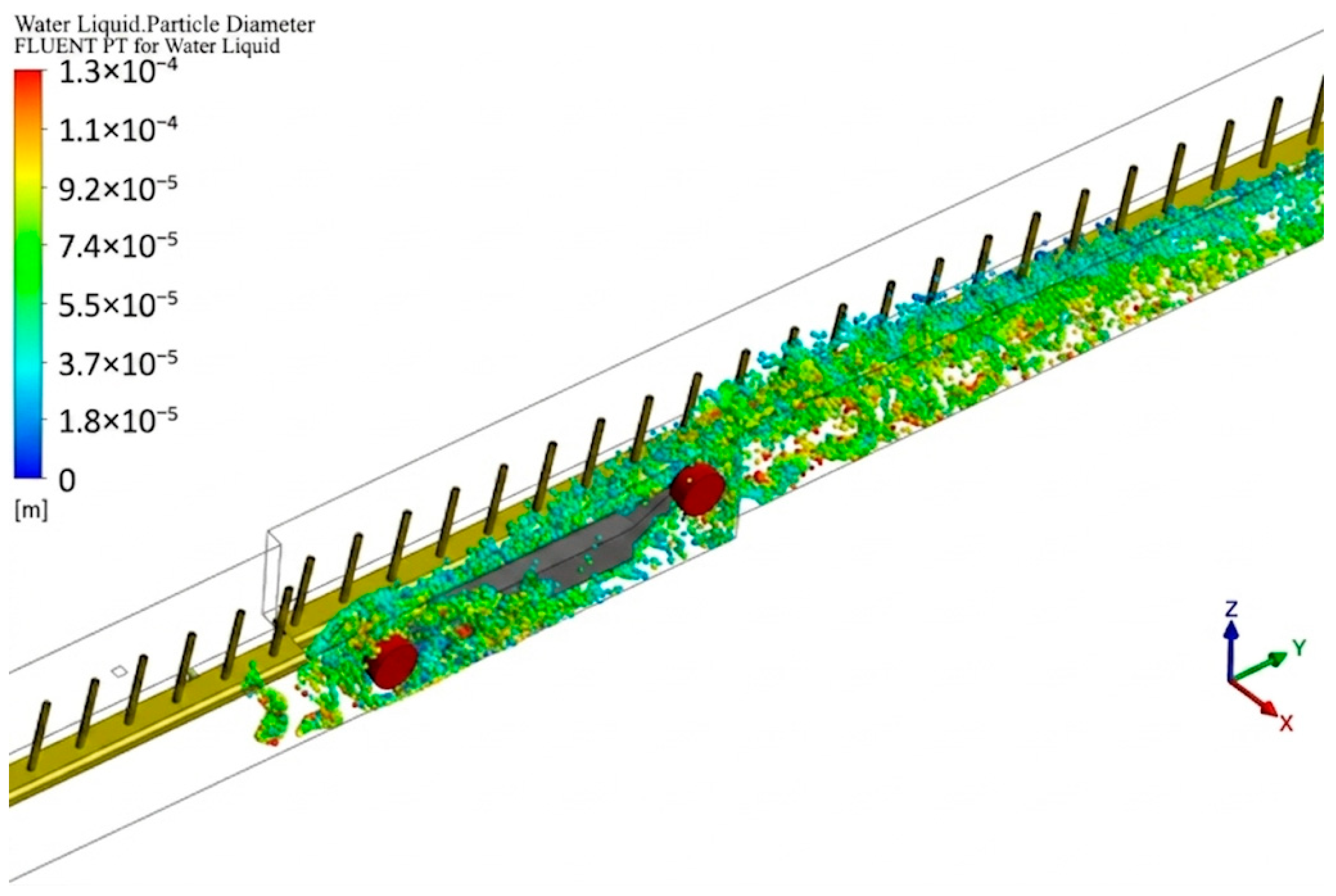
The external spray of the coal shearer can completely cover the front and rear drum areas of the coal shearer. The diameter of the droplet particles is basically less than 130 μm, and they are very light in weight and quickly blown to the downwind side by the air flow for diffusion. As can be observed from Figure 9, the mist field of the external nozzles of the coal shearer basically covers the migration path of the dust from the drum to the downwind side. This fully covered spray mist curtain can effectively suppress the large amount of dust generated when the drum cuts the coal body, prevent the dust from spreading into the working space, and control the dust spread at the source of dust generation.
Figure 9.
Coal miner external nozzle spray distribution.
3.3.3. The Distribution Pattern of Droplet Concentration
After the coal cutter in the fully mechanized mining face cuts coal and generates dust, most of the dust moves along the downwind side of the wall, while a small portion spreads to the sidewalk area [21]. After the external spray of the coal cutter is turned on, the droplet concentration in the fully mechanized mining face, shown in Figure 10, can basically cover the dust area on the downwind side of the coal cutter. Two observation lines are set at the height of the breathing zone on the sidewalk side and the coal cutter side.
Figure 10.
Distribution of droplet concentration in the external nozzle of the coal miner.
The droplet concentration produced by the nozzles outside the coal shearer can exceed 0.01 kg/m3 at its highest level. The high-concentration areas are mainly concentrated on the downwind sides of the front and rear drums, which can basically fully cover the dust sources generated by the drum cutting and settle the high-concentration dust on the downwind side of the coal shearer. Ten meters away from the downwind side of the front drum of the coal shearer, the droplet concentration began to continuously decrease. In addition, as the droplets are constantly settling, a large number of droplets are also accumulating at the bottom plate.
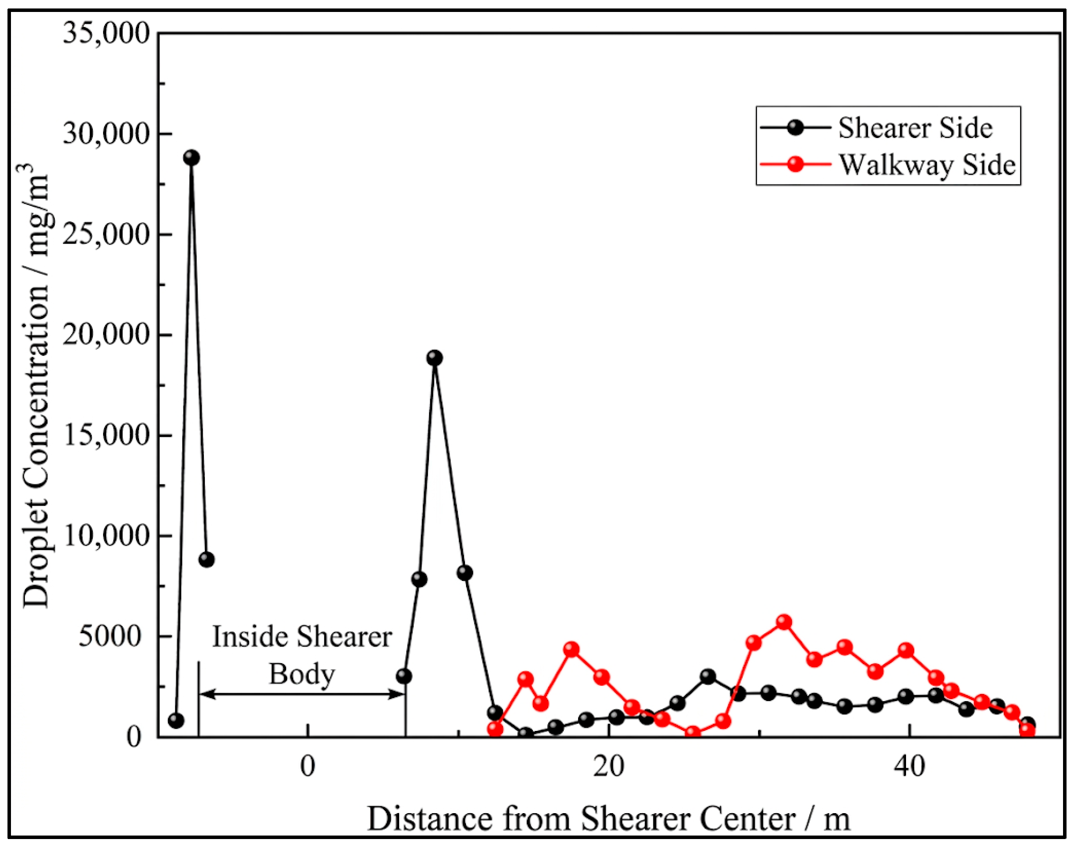
As can be observed from Figure 11, when the outer nozzle of the coal shearer is opened, the droplet concentration in the entire coal cutting area of the coal shearer is relatively high. At the height of the breathing zone on the side of the coal shearer, the droplet concentration at the rear drum, which is −6 to −10 m away from the center of the coal shearer, is as high as 28,786 mg/m3. At the front drum and rocker arm, which are 6 to 10 m away from the center of the coal shearer, the droplet concentration reached 18,860 mg/m3, and then it continuously decreased, eventually remaining at 2000–3000 mg/m3. At the height of the breathing zone on the sidewalk side, due to the continuous diffusion and sedimentation of fog droplets at the coal mining machine, the fog droplet concentration rose twice, reaching 4342 mg/m3 and 5715 mg/m3, respectively.
Figure 11.
Coal miner external nozzle breathing zone droplet concentration map.
3.4. Analysis of Simulation Results of Three Inter-Frame Spray Ejection Dust Removal Devices
The dust generated during the relocation of hydraulic supports is mainly concentrated in the gap areas between adjacent supports. As pedestrian passages are usually set directly beneath this area, the dust poses a direct threat to the safety of miners [17]. Therefore, during the movement of the hydraulic support, the inter-support spray ejection dust removal system must be simultaneously activated. Through negative-pressure dust suction and spray dust suppression, the spread of dust can be effectively controlled.
3.4.1. Flow Distribution Law
The suction effect of the spray jet dust removal device is shown in Figure 12.
Figure 12.
Simulation of air suction effect of inter-shelf spray-induced dust removal device.
As can be seen from Figure 12, after the spray jet dust removal device is turned on, its spray system can form a high-density water mist barrier covering the entire cross-section of the tunnel. Moreover, the dust suction ports set at the rear and sides of the device can efficiently capture suspended dust particles in the sidewalk area under negative pressure.
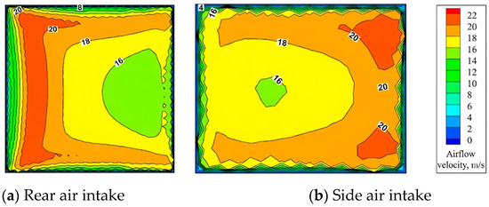
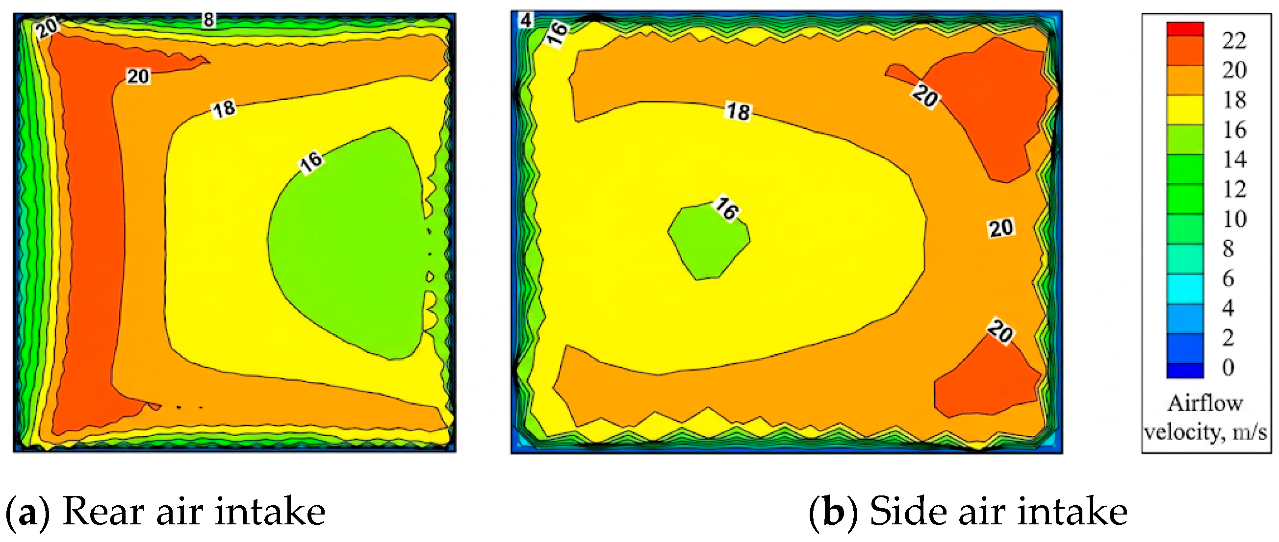
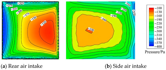
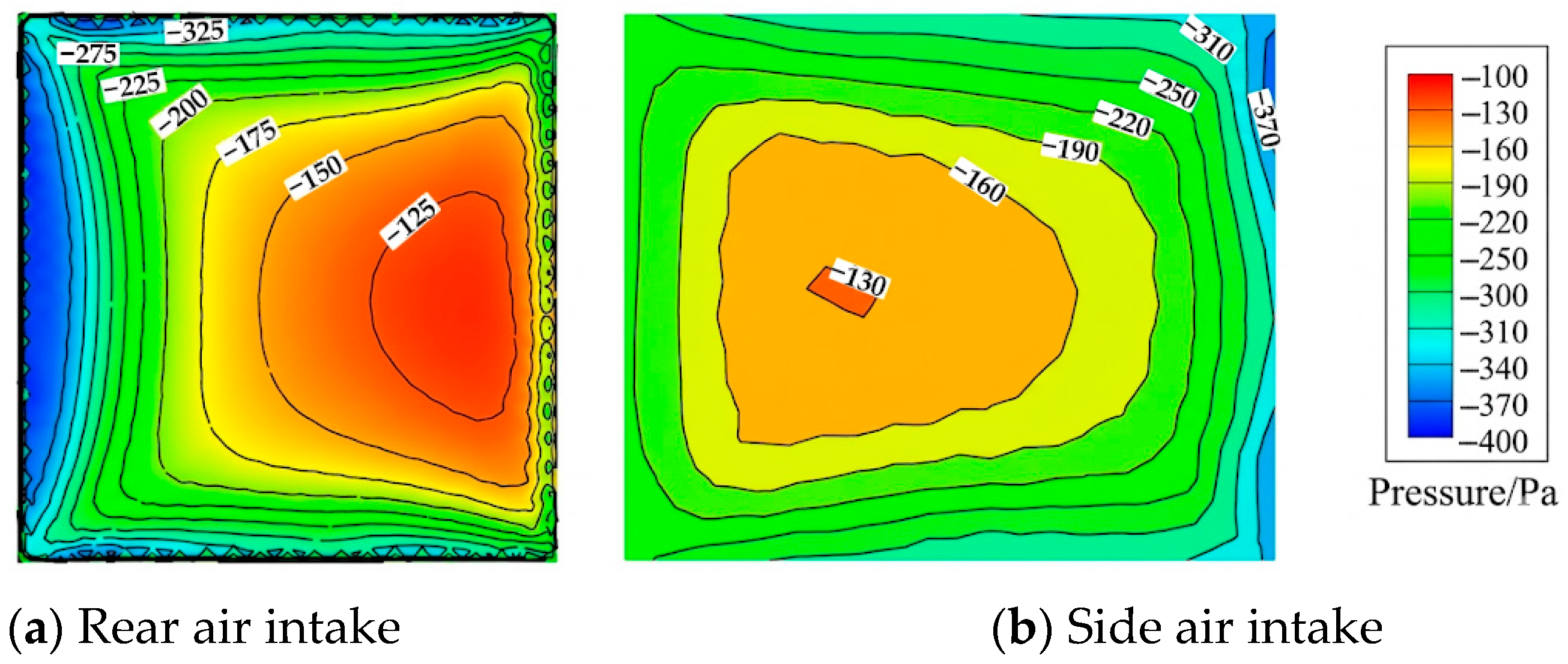
Under high pressure, high-speed jet droplets are ejected from the front of the spray ejection dust removal device, forming a low-pressure area in the ejection chamber. The rear and side suction ports of the device draw in the surrounding dusty air flow. The maximum wind speed at the rear suction port reaches 21.5 m/s, and the maximum negative pressure reaches −386.1 Pa. The maximum wind speed at the side suction port reaches 21.8 m/s. The maximum negative pressure reaches −394.4 Pa, as shown in Figure 13 and Figure 14.
Figure 13.
Wind speed of suction outlet of inter-shelf spraying and ejecting dust removal device.
Figure 14.
Pressure at suction outlet of inter-shelf spray-induced dust removal device.
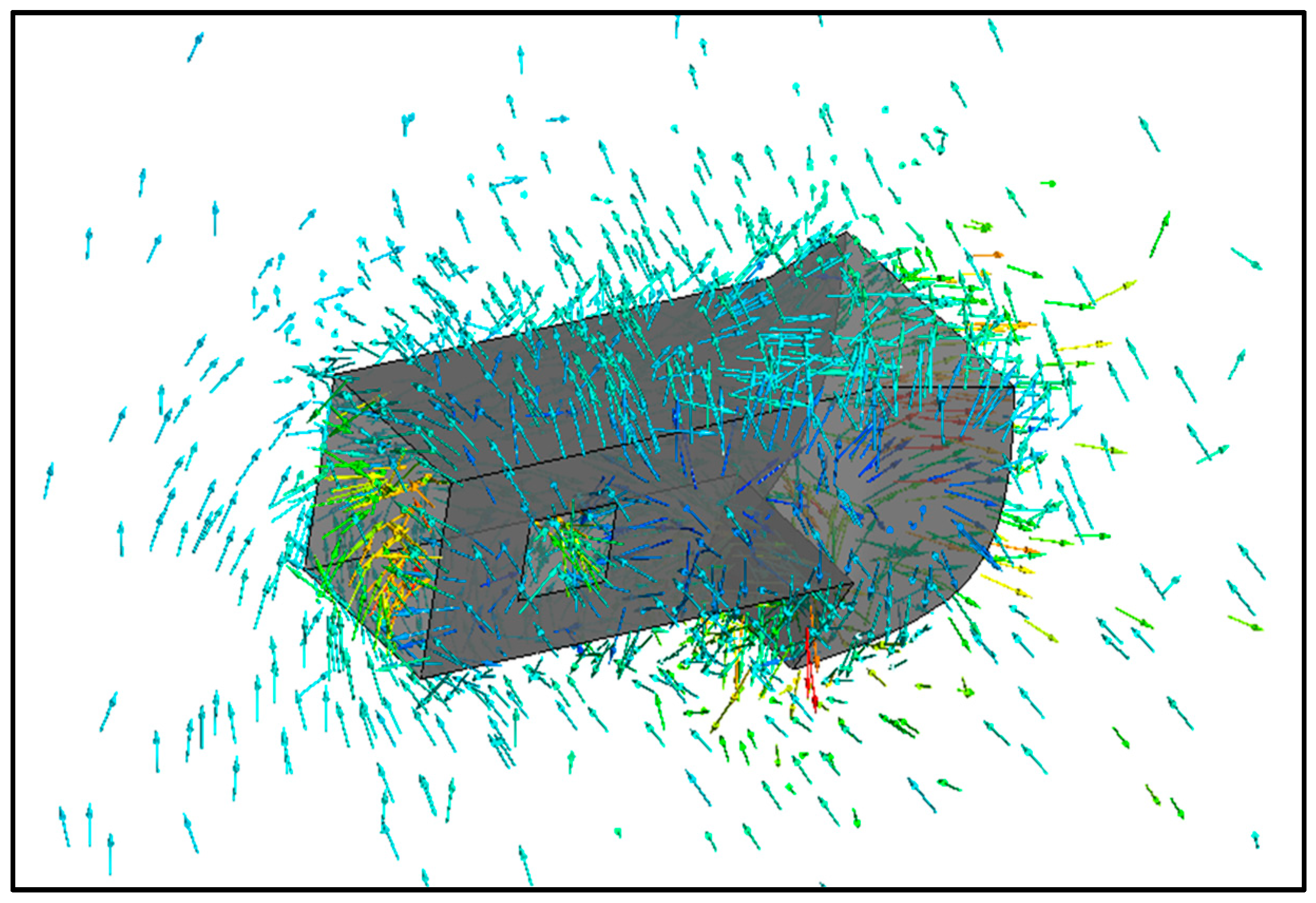
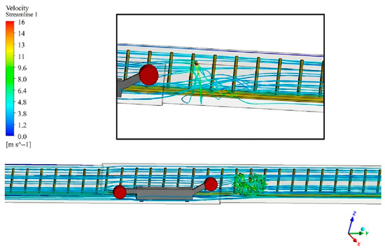
As can be seen from Figure 15, when the air flow at the working face reaches the upwind side of the spray jet dust removal device, it will change its motion state under the influence of the spray field. Below the device nozzle, the air flow trace deflects, and at the same time, the wind speed increases to 15.8 m/s, and the air flow moves towards the bottom plate.
Figure 15.
Trace of wind flow in the vicinity of a spray-induced dust removal device.
3.4.2. The Distribution Pattern of Droplet Particles
As can be seen from Figure 16, after the spray jet dust removal device sprays liquid droplets, they will undergo atomization to form a group of small particle droplets. At t = 1 s, the high-pressure nozzle rapidly atomizes the water into fine droplets. At this point, the diffusion of the droplets has just begun, mainly concentrated within the close range of the nozzle, and has not spread throughout the entire hydraulic support space. At t = 5 s, the fog field has already covered the entire height of the working surface. The less rapid fog droplets are carried by the airflow to the downwind side of the nozzle, reaching up to approximately 10 m at the farthest. Some of the droplets settle under the force of gravity, while others keep moving towards the outlet with the airflow. At t = 10 s, the droplets have already moved 20 m to the downwind side of the nozzle, and the diffusion speed has significantly slowed down and tended to stabilize, forming a uniform water mist layer. Meanwhile, with the evaporation of the droplets and the influence of air flow, the droplets eventually tend to disperse.
Figure 16.
Front view of the droplet position of the spray-induced dust removal device at different times.
As can be seen from Figure 17, at t = 1 s, water mist is ejected at high speed from the nozzle. These droplets, having just formed, are large in size and numerous in quantity. Some of the droplets move towards the hydraulic support, which is due to the suction effect of the air flow near the spray jet dust removal device. The high-speed air flow keeps moving towards the suction port, while a small number of droplets with a lower speed move along the direction of the air flow suction. However, at this time, the sidewalk side has not been significantly affected. At t = 5 s, on the coal wall side, the mist droplets continue to spray out and collide with each other. Some of the mist droplets start to refine, forming smaller particles. Meanwhile, the fog droplets began to spread further towards the sidewalk. The concentration of fog droplets on the sidewalk side started to gradually increase, but the coverage area was still relatively small. When t = 10 s, 5 m away from the downwind side of the nozzle, more droplets spread towards the sidewalk side, forming a stable water mist layer that captures and settles dust particles in the air.
Figure 17.
Top view of spray-induced dust removal device droplet positions at different times.
3.4.3. The Distribution Pattern of Droplet Concentration
As shown in Figure 18, after the spray jet dust removal device is turned on, the high-pressure droplets leave the device and form a high-concentration conical fog field between the device and the coal wall. At the coal wall, the high-concentration droplets can cover about 10 m in length, forming a dense droplet barrier, effectively preventing the high-concentration dust generated during coal cutting and the movement of the hydraulic support from spreading to the downwind side.
Figure 18.
Distribution of droplet concentration in spray-induced dust removal device.
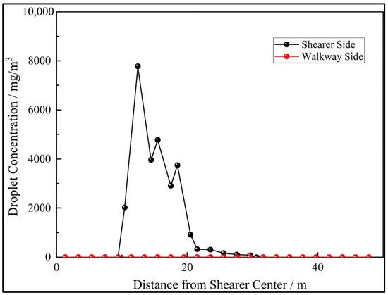
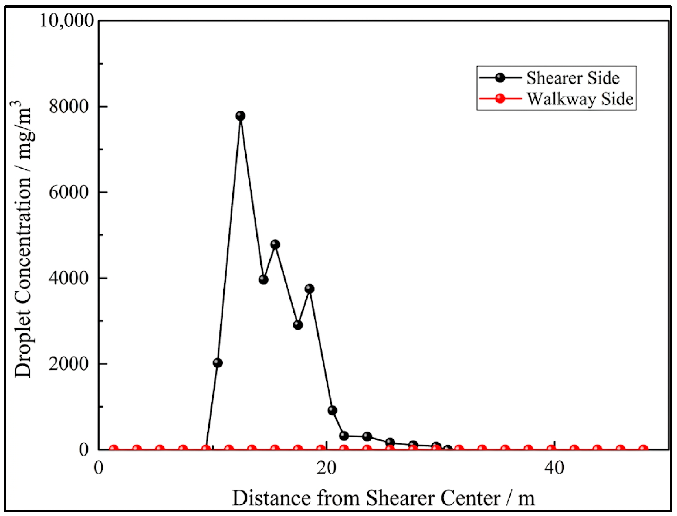
As shown in Figure 19, the high-concentration droplet band about 10 m long formed by the spray jet dust removal device on the side of the coal shearer is located 10 to 20 m away from the center of the coal shearer, and the maximum height in the breathing zone can reach 7779 mg/m3. Due to the suction effect of the spray jet dust removal device, a small number of droplets enter the sidewalk side, but the concentration is relatively low.
Figure 19.
Concentration of droplets in the respiratory zone of a spray-induced dust removal device.
3.5. Analysis of Simulation Results of the Combined Spray Dust Suppression System
The combined spray dust suppression system simultaneously activates the interframe spray ejection dust removal devices on the downwind side of the coal shearer and in the hydraulic support relocation area. The spray jet dust removal device sucks in the dusty air flow from the sidewalk area through the rear and side suction ports and is used in conjunction with the external spray of the coal shearer. Eventually, the droplets can form a cross-sectional coverage throughout the fully mechanized mining face.
As can be seen from Figure 20, when the combined spray system can cover most of the fully mechanized mining face, the mist droplets can reach a cross-sectional coverage from the left side of the hydraulic support frame to the right side of the coal wall, from the top plate to the bottom plate, and the front and rear rollers can be closely covered by the mist field. Large droplets over 100 μm in diameter rapidly settle as they move with the airflow, reaching 30 m on the downwind side of the coal shearer and already reaching the bottom plate, where they gather. In contrast, small droplets under 30 μm in diameter settle more slowly and float on the upper layer of the working face.
Figure 20.
Combined fog field simulation results.
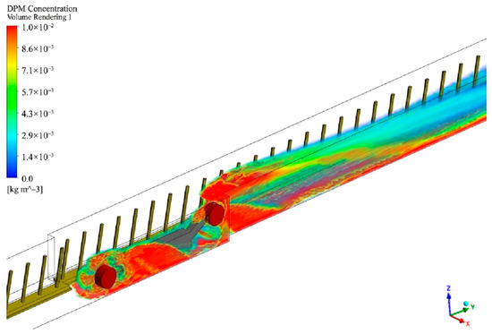
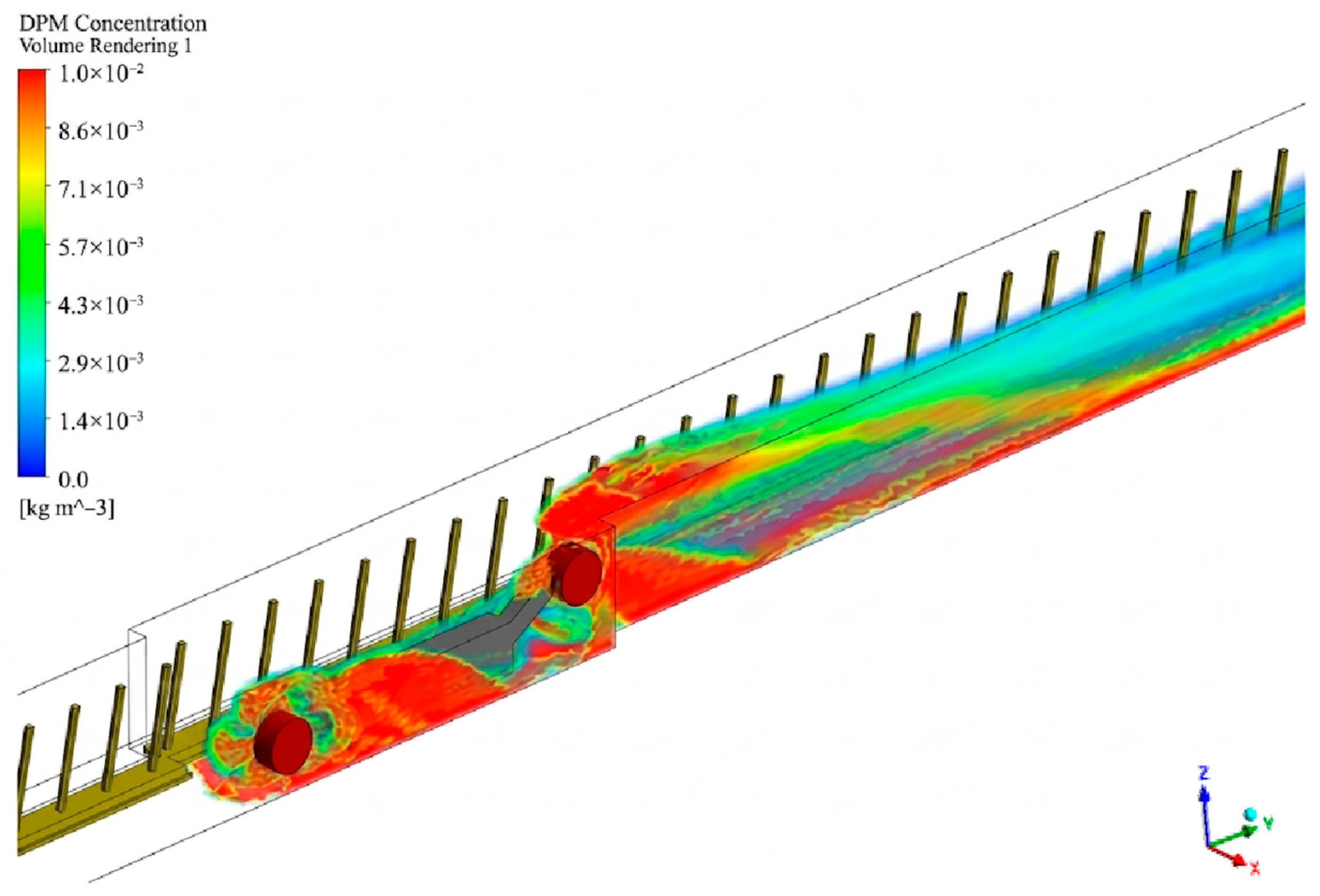
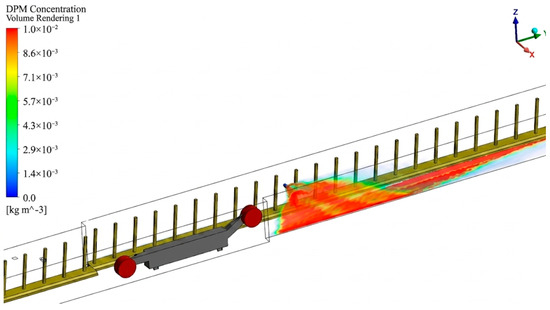
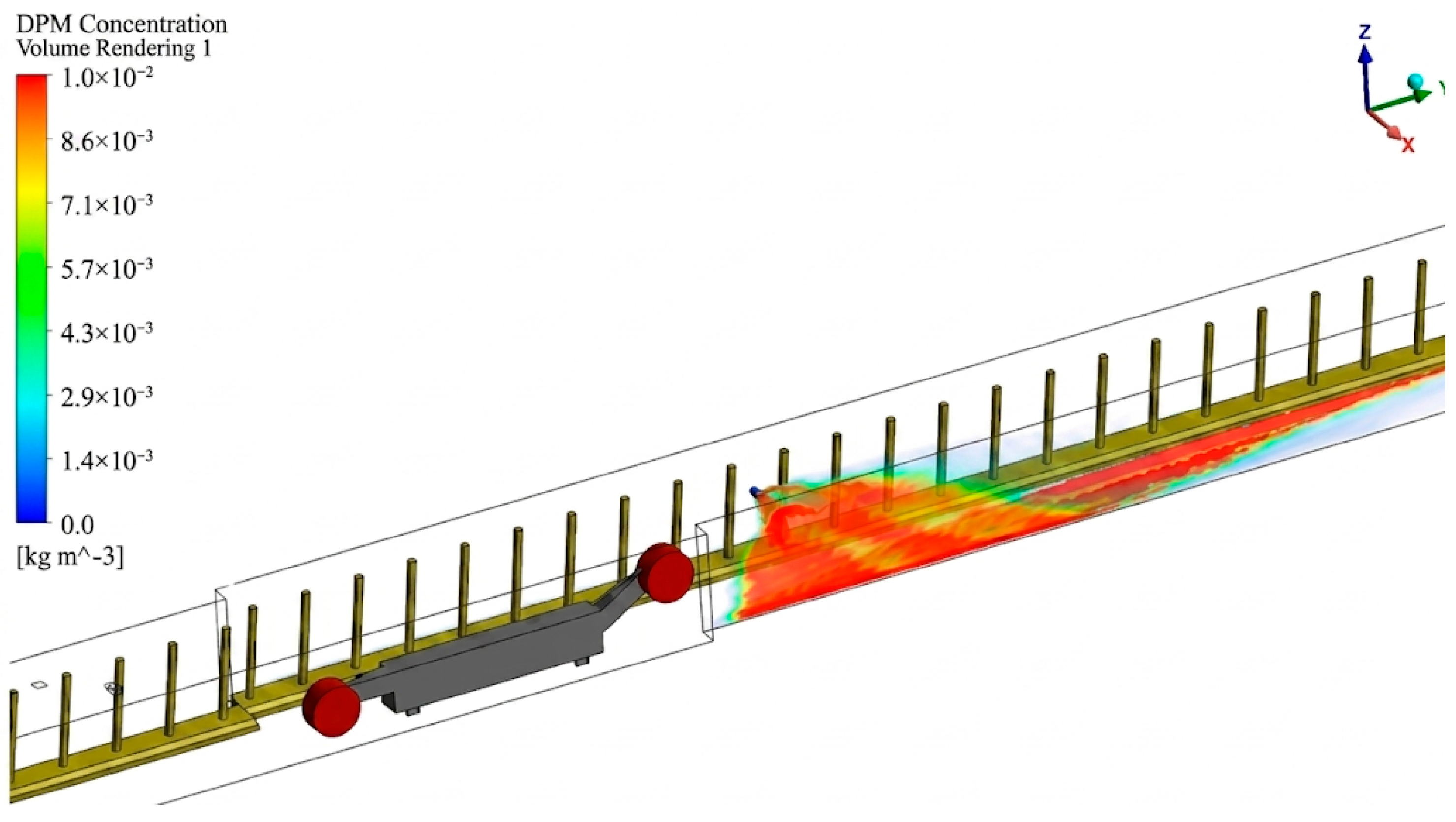
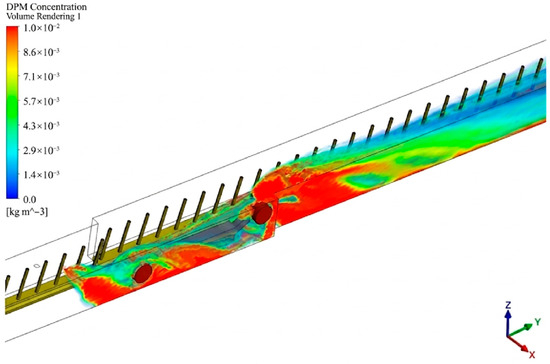
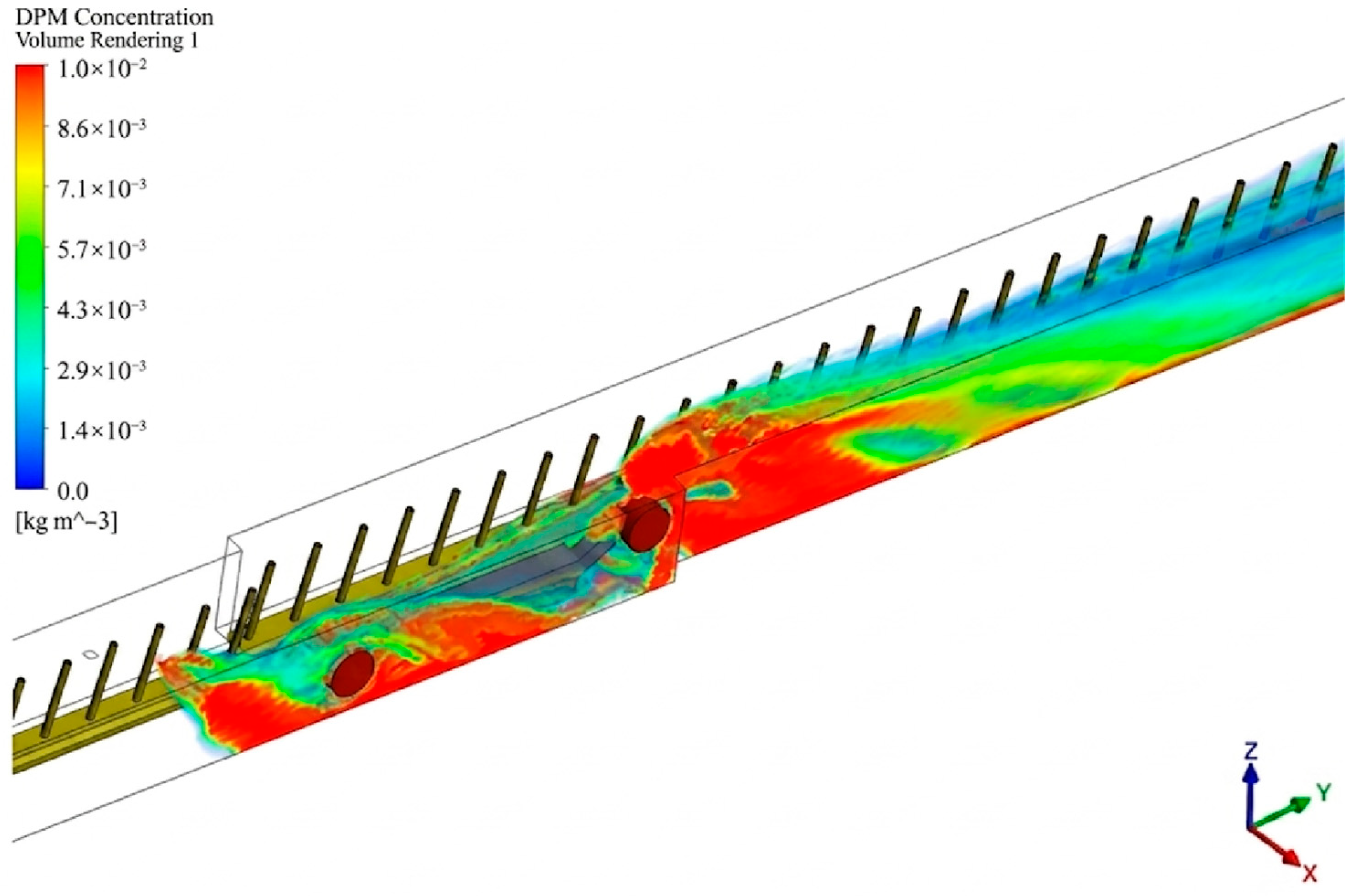
As can be seen from Figure 21, when the combined spray is activated, the fully mechanized mining face is covered with high-concentration droplets. The areas with the highest droplet concentration are near the nozzles, located at the locations where the hydraulic support is moved, at the spray ejector dust removal device on the downwind side of the shearer, and at the nozzles outside the front and rear rollers of the shearer. The droplet concentration can be as high as 0.01 kg/m3 and gradually decreases after passing through the nozzles. The droplet distribution shows the characteristics of “three highs area” and “post-nozzle attenuation”.
Figure 21.
Combined Spray System Spray Concentration Chart.
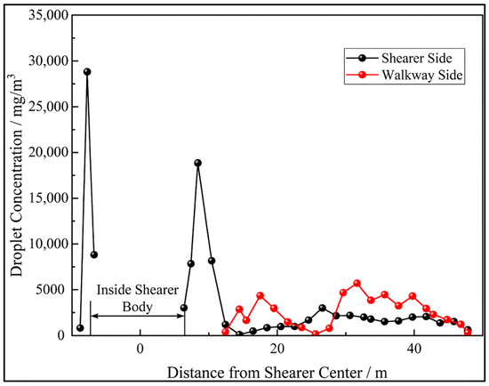
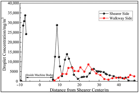
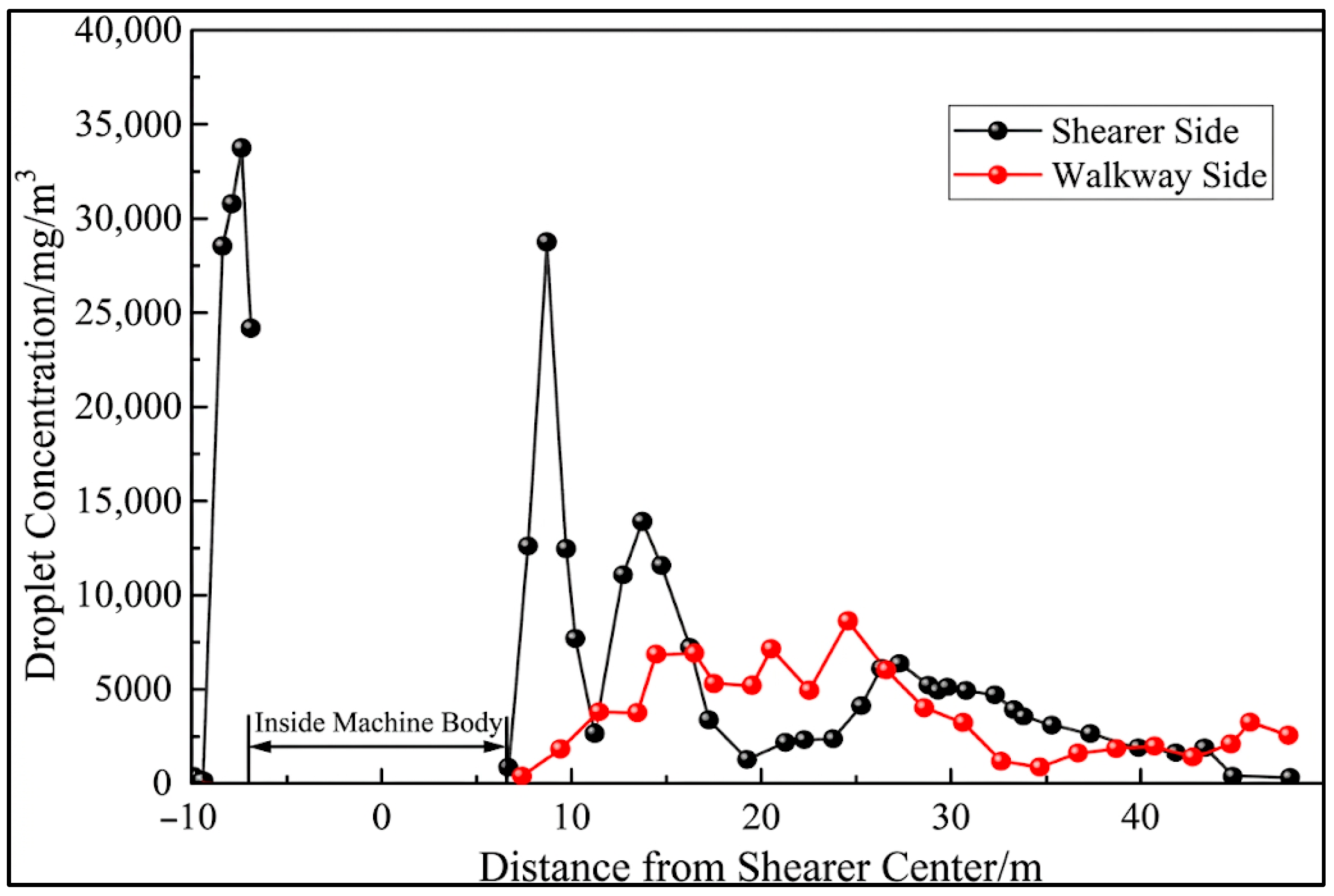
As can be seen from Figure 22, at the height of the breathing zone on the side of the coal shearer, at −6 to −10 m from the center of the coal shearer and at 6 to 10 m from the center of the coal shearer at the front and rear rocker arms and drums, the dromist concentration is in the high-concentration range, with the highest reaching 33,739 mg/m3 and 28,750 mg/m3, respectively. Due to the shielding of the machine body and rocker arms at the center of the coal shearer, there is no data available. When passing through the spray jet dust removal device on the downwind side of the coal shearer, the droplet concentration rose again to 13,925 mg/m3 and then continuously decreased. Twenty-three meters from the center of the coal shearer, as the fog droplets at the higher part of the working face gradually settled to the height of the breathing zone, the fog droplet concentration at the breathing zone height rose again to 6376 mg/m3. At the height of the breathing zone on the sidewalk side, due to the effect of air flow, the mist droplets from the outer nozzles of the coal shearer diffuse to the sidewalk. Moreover, due to the suction effect of the air flow near the spray jet dust removal device, a small number of mist droplets with lower speeds move in the direction of the air flow suction. Therefore, the concentration of mist droplets on the downwind side of the coal shearer gradually increases and can reach 6000 to 8000 mg/m3 at a distance of 20 to 30 m from the center of the coal shearer.
Figure 22.
Integrated Spray System Breathing Belt Droplet Concentration Chart.
In conclusion, the combined spray system simultaneously activates multiple nozzles to work in synergy, which can form a high-density droplet barrier, block the diffusion path of dust, control the dust at the source of dust generation, and improve the efficiency of spray dust suppression.
4. Analysis of Simulation Results
The particle size distribution and velocity distribution of droplets are the two most important parameters affecting the dust suppression efficiency [22]. Ma Xiao [17] conducted experiments on the droplet characteristics of the spray field and measured the droplet size produced by the B2# nozzle. It was found that the optimal droplet size distribution of the B2# nozzle spray field was between 30 μm and 120 μm. Within this range, the smaller the particle size, the higher the dust removal efficiency. Therefore, in this section, the effectiveness of the spray dust suppression system in dust suppression is verified by comparing the particle size and velocity of the droplets in the spray field with the experimental data of Ma Xiao.
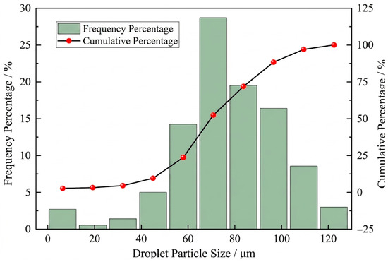
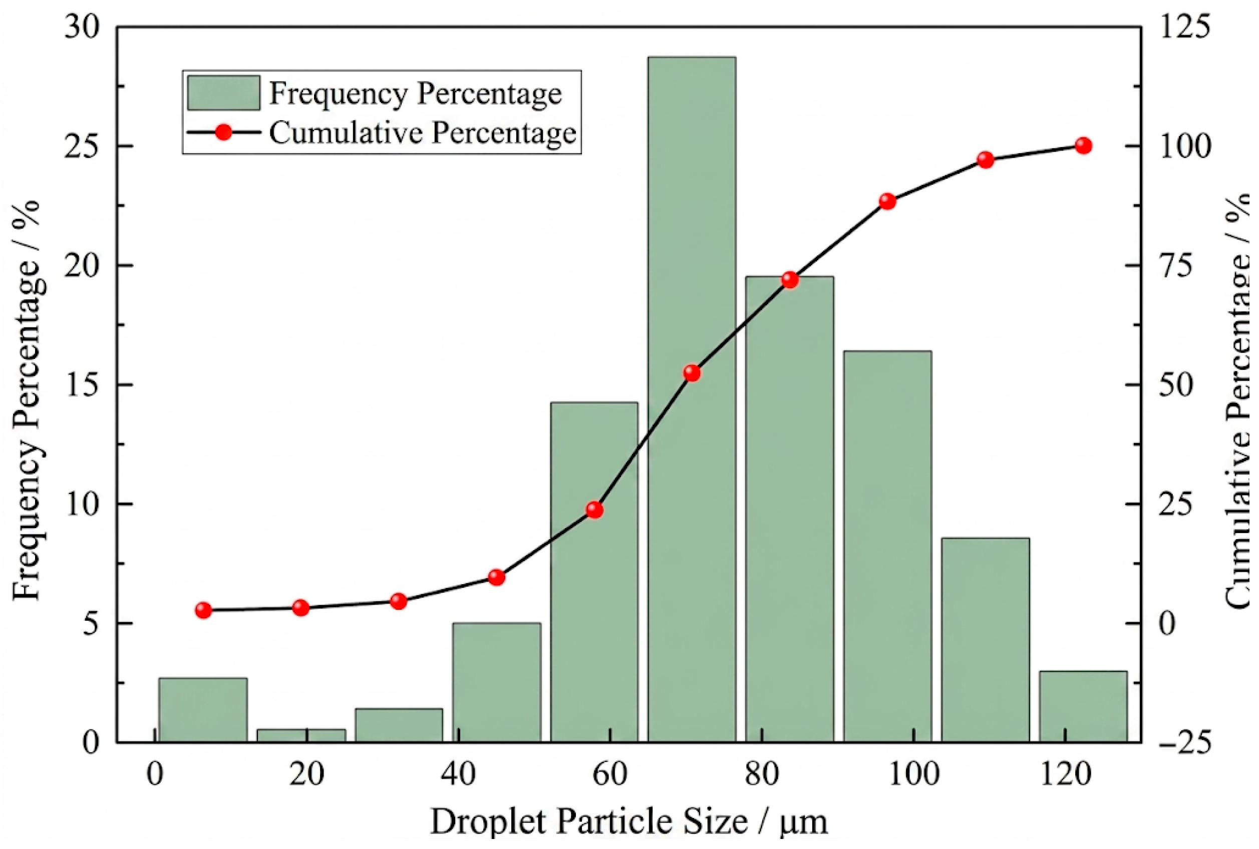
As shown in Figure 23, in the fully mechanized mining face, the proportion of droplets with a particle size less than 30 μm in the combined spray system is 3.21%, the proportion of droplets with a particle size greater than 120 μm is 2.98%, and the proportion of droplets with a particle size between 30 μm and 120 μm is 93.81%. Among them, the proportion of droplets with a particle size of 70.85 μm is the highest, reaching 28.72%. From this, it can be seen that the proportion of the optimal droplet size in the fully mechanized mining face is 93.81%, and the proportion of small droplets with a particle size of less than 80 μm is 72%. The dust removal efficiency can be considered good.
Figure 23.
Combined spray particle size distribution.
If the droplet velocity is too low, it may cause the droplets to be carried away by the airflow or evaporate, thereby reducing the dust-collection effect. On the other hand, if the velocity is too high, it may disrupt the stability of the flow field and lead to secondary dust rising [23].
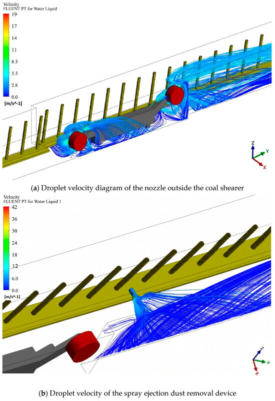
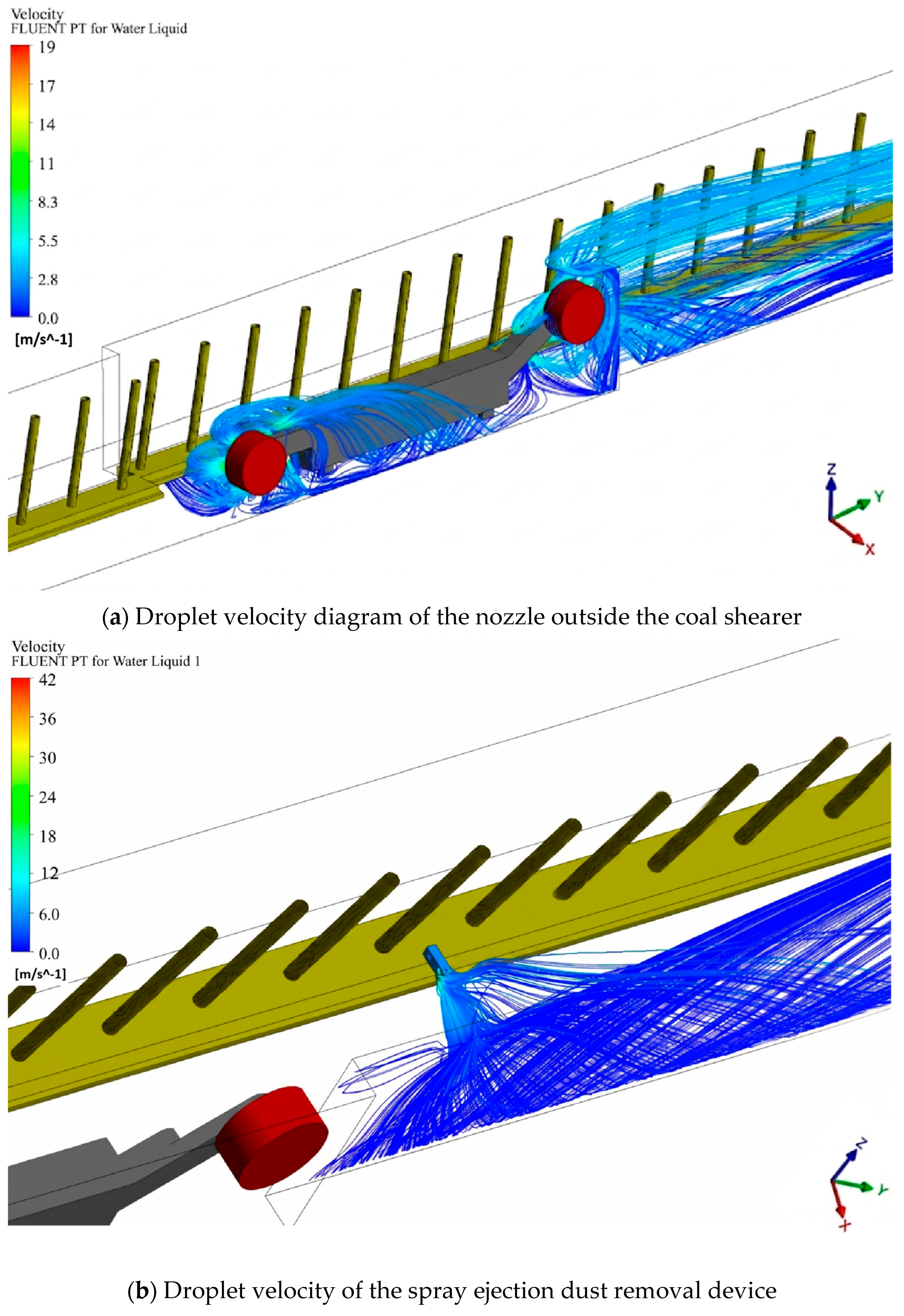
As can be seen from Figure 24, the droplet speed is the maximum when it just leaves the nozzle, and it decreases as it moves further away from the nozzle. Just when the droplet speed of the nozzle outside the coal shearer leaves the nozzle, the maximum speed can reach 19.2 m/s, and the maximum droplet speed of the spray ejection dust removal device can reach 42.2 m/s. This can ensure efficient dust removal while avoiding excessive evaporation of droplets or negative impacts on the working environment. Compared with the droplet velocity of the external nozzle of the coal shearer, the droplet velocity of the spray jet dust removal device with negative pressure is significantly greater. This phenomenon conforms to the Venturi effect in fluid mechanics. When the spray fluid flows from the expansion section to the contraction section, the fluid velocity is bound to increase.
Figure 24.
Spray field droplet velocity.
As shown above, the majority of the spray particle sizes in the spray field are within the range of 30 μm to 120 μm, which conforms to the optimal droplet size distribution range, and the droplet velocity in the spray field is within a reasonable range. Therefore, it can be considered that the combined spray field has a better droplet dust capture efficiency.
5. Conclusions
(1) The coal dust at the Taigemiao working face exhibits distinct hydrophilic characteristics. Leveraging this property, a combined spray dust suppression system—integrating the shearer’s external spray and the inter-support spray-induced dust removal device—was developed. This system achieves comprehensive control over the two primary dust-generation sources (shearer cutting and hydraulic support advancement), effectively forming a continuous droplet barrier that covers the entire working face area.
(2) The key droplet parameters of the combined spray system fully satisfy the criteria for highly efficient dust capture. Droplets within the optimal size range of 30–120 μm account for 93.81% of the total spray, with fine droplets under 80 μm comprising 72%, demonstrating a robust capacity for capturing respirable dust. Furthermore, the maximum droplet velocity reaches 19.2 m/s for the shearer’s external nozzles and 42.2 m/s for the inter-support device. This velocity attenuates along a gradient with distance, which guarantees high dust capture efficiency while strictly preventing secondary dust re-entrainment. Overall, the dust suppression performance of the combined system is significantly superior to that of an isolated, single-spray setup.
(3) It should be noted that the current study primarily focuses on the theoretical design and numerical simulation of the combined spray dust suppression system. While the simulation results demonstrate a high theoretical dust capture efficiency, these findings primarily serve as a theoretical basis and technical reference. Future research will focus on conducting comprehensive field industrial tests at the Taigemiao mining face to empirically validate the simulation results and further optimize the system parameters under complex real-world conditions.
Author Contributions
Conceptualization, Y.L. and Y.C.; methodology, Y.L. and Y.C.; software, J.L.; validation, J.L. and Z.S.; formal analysis, J.L. and Z.S.; investigation, Z.S.; resources, C.X.; data curation, J.L.; writing—original draft preparation, J.L.; writing—review and editing, Y.L.; visualization, Y.L.; supervision, Y.C.; project administration, C.X.; funding acquisition, Y.C. and Y.L. All authors have read and agreed to the published version of the manuscript.
Funding
This research was funded by the Key Research Program of China Coal Science and Industry Group, (grant number 2024-TD-ZD011-02); the Scientific Research Project of Chinese Institute of Coal Science, (grant number 2025-MKZY-ZL-001); and the National Natural Science Foundation of China, (grant number 52204220).
Data Availability Statement
The raw data supporting the conclusions of this article will be made available by the authors on request.
Acknowledgments
The authors have reviewed and edited the output and take full responsibility for the content of this publication.
Conflicts of Interest
Authors Yingjie Liu, Yongbo Cai, and Zuo Sun were employed by the company Tiandi Science and Technology Co., Ltd. The remaining authors declare that the research was conducted in the absence of any commercial or financial relationships that could be construed as a potential conflict of interest.
References
- Xu, C.; Yang, T.; Wang, K. Gas extraction of coal seam roof fractured zone in China: A review. Fuel 2024, 357, 129930. [Google Scholar] [CrossRef] [Scilit]
- Xu, C.; Ma, S.; Wang, K. Stress and permeability evolution of high-gassy coal seams for repeated mining. Energy 2023, 284, 128601. [Google Scholar] [CrossRef] [Scilit]
- Perret, J.L.; Plush, B.; Lachapelle, P.; Hinks, T.S.; Walter, C.; Clarke, P. Coal mine dust lung disease in the modern era. Respirology 2017, 22, 662–670. [Google Scholar] [CrossRef] [Scilit] [PubMed]
- Zhang, J.; Han, Z.; Chen, T.; Yao, N.; Yang, X.; Chen, C. A numerical simulation of the coal dust migration law in directional air drilling in a broken soft coal seam. Processes 2024, 12, 309. [Google Scholar] [CrossRef] [Scilit]
- Shekarian, Y.; Rahimi, E.; Rezaee, M.; Su, W.C.; Roghanchi, P. Respirable coal mine dust: A review of respiratory deposition, regulations, and characterization. Minerals 2021, 11, 696. [Google Scholar] [CrossRef] [Scilit]
- Liu, Q.; Nie, W.; Hua, Y.; Peng, H.; Liu, C.; Wei, C. Research on tunnel ventilation systems: Dust diffusion and pollution behaviour by air curtains based on CFD technology and field measurement. Build. Environ. 2019, 147, 444–460. [Google Scholar] [CrossRef] [Scilit]
- Torno, S.; Toraño, J.; Álvarez-Fernández, I. Simultaneous evaluation of wind flow and dust emissions from conveyor belts using computational fluid dynamics (CFD) modelling and experimental measurements. Powder Technol. 2020, 373, 310–322. [Google Scholar] [CrossRef] [Scilit]
- Fu, W.; Song, H.; Chen, X.; Zhang, Z.; Xu, C.; Liu, Q.; Zhang, X. Collaborative dust control and dry purification technology and equipment development of turbulent air chamber in fully mechanized excavation face. J. Min. Sci. Technol. 2025, 10, 705–713. [Google Scholar] [CrossRef]
- Wang, P.F.; Liu, R.H.; Gui, Z.; Gou, S.-X.; Shu, W.; Tan, X.-H. Theoretical research on atomization characteristics and dust suppression efficiency of air-water spray in underground coal mine. J. China Coal Soc. 2016, 41, 2256–2262. [Google Scholar] [CrossRef]
- Aziz, N.; Cram, K.; Hewitt, A. Mine Dust and Dust Suppression. In Australasian Coal Mining Practice, 3rd ed.; Kininmonth, R.J., Baafi, E.Y., Eds.; Monograph 12; AusIMM: Carlton, Australia, 2009; pp. 646–659. ISBN 978-1-921522-07-9. [Google Scholar]
- Ren, T.X.; Plush, B.; Aziz, N. Dust controls and monitoring practices on Australian longwalls. Procedia Eng. 2011, 26, 17–29. [Google Scholar] [CrossRef] [Scilit]
- Parra, M.; Villafruela, J.M.; Castro, F.; Mendez, C. Numerical and experimental analysis of different ventilation systems in deep mines. Build. Environ. 2006, 41, 87–93. [Google Scholar] [CrossRef] [Scilit]
- Nie, W.; Liu, Y.; Cheng, W.; Zhou, G.; Ma, X. Spray jet dust removal technology between fully mechanized mining face frames. J. Cent. South Univ. (Nat. Sci. Ed.) 2015, 46, 4384–4390. [Google Scholar]
- Wang, X.; Xie, H.; Chen, J.; Zhang, C. Optimization of spray dust reduction technology between frames in fully mechanized caving face. Coal Eng. 2008, 40, 50–52. [Google Scholar] [CrossRef]
- Hu, Z.; Zhang, B.; Chang, H. A Study on Dust-Control Technology Used for Large Mining Heights Based on the Optimization Design of a Tracking Spray Nozzle. Atmosphere 2023, 14, 627. [Google Scholar] [CrossRef] [Scilit]
- Jing, D.; Jiang, Z.; Ren, S.; Meng, X.; Ge, S.; Zhang, T. Study on Dust Migration Law and Spray Dust Suppression Technology in Fully Mechanized Mining Face. Eng 2023, 4, 121–135. [Google Scholar] [CrossRef] [Scilit]
- Xiu, Z.; Nie, W.; Chen, D.; Yan, J.; Cai, P.; Liu, Q.; Wei, C. Numerical simulation study on the coupling mechanism of composite-source airflow–dust field in a fully mechanized caving face. Powder Technol. 2019, 356, 443–457. [Google Scholar] [CrossRef] [Scilit]
- Zhou, Z.; Chen, Z.; Liu, L.; Zhong, F.; Guo, Y.; Zhang, J.; Luo, B.; Lai, Z. Simulation research on the inner flow field of low-resistance Venturi vibrating string grid dust removal system. J. Min. Sci. Technol. 2024, 9, 88–97. [Google Scholar] [CrossRef]
- Ma, X. Research on Spray Atomization Law and Dust Suppression Technology in Fully Mechanized Mining Face. Master’s Thesis, Shandong University of Science and Technology, Qingdao, China, 2017. [Google Scholar]
- Xiao, J. Research and Application of Spray Dust Suppression Technology in the 2-208 Working Face of Xinzhi Coal Mine. Coal Mine Mod. 2021, 30, 46–48. [Google Scholar]
- Chen, F.; Mo, J.; Ma, W. Study on the coupling migration law of airflow-respiratory dust of an 8-m high fully-mechanized mining face. Energy Explor. Exploit. 2022, 40, 1360–1381. [Google Scholar] [CrossRef] [Scilit]
- Hou, J. Study on High-Efficiency Swirl Atomization Nozzle and Spray Dust Suppression Characteristics in Fully Mechanized Mining Face. Ph.D. Thesis, China University of Mining and Technology, Xuzhou, China, 2024. (In Chinese) [Google Scholar] [CrossRef]
- Jiang, B.; Qi, Y.; Zhang, J.; Guo, L.; Li, J.; Xiao, Y. Research Status and Prospect of Coal Mine Dust and Mist Condensation for Dust Suppression Efficiency Enhancement. Coal Sci. Technol. 2025, 53, 183–200. [Google Scholar]


Disclaimer/Publisher’s Note: The statements, opinions and data contained in all publications are solely those of the individual author(s) and contributor(s) and not of MDPI and/or the editor(s). MDPI and/or the editor(s) disclaim responsibility for any injury to people or property resulting from any ideas, methods, instructions or products referred to in the content. |
© 2026 by the authors. Licensee MDPI, Basel, Switzerland. This article is an open access article distributed under the terms and conditions of the Creative Commons Attribution (CC BY) license.