


Abstract
Deciphering the dynamic fracture evolution of rock masses, particularly the interaction between dynamic stress waves and localised weak interlayers, is essential for optimising dynamic rock excavation in mining engineering. To systematically explore how these structural planes halt propagating cracks and generate a dynamic shielding effect, this study integrated Split Hopkinson Pressure Bar experiments, Digital Image Correlation techniques, and computational modeling. The findings demonstrate that altering the geometric orientation of the soft layer dictates the ultimate failure pattern. While an orthogonal interface (i.e., an interface with 0° inclination perpendicular to the loading direction) allows a tension-driven crack to cleave directly through the entire composite specimen, introducing an inclined obliquity of 15° forces the advancing fracture to deviate and permanently halt inside the soft stratum. Macroscopically, this barrier capability is validated by a rapid decrease in fracture speed, which drops abruptly by 75.5% upon encountering the inclined zone. Microscopic numerical evaluations confirm that this fracture arrest originates from wave mode conversion at the misaligned boundary. The angled interface forces incoming compressional pulses to transform into intense shear stresses, promoting extensive fracture. Substantial energy dissipation within the interlayer fully deprives the primary crack of the tensile stress required for propagation, effectively confining the stress-propagated hard rock within an energy shadow zone and suppressing further fragmentation.
1. Introduction
In underground mining operations, the drill-and-blast method remains the most prevalent technique for rock excavation and ore extraction [1,2]. The efficiency of blast-induced rock fragmentation is directly tied to the productivity, downstream comminution costs, and overall economics of the entire mining cycle. However, in actual engineering practice, ore bodies and their surrounding rocks frequently occur as layered rock masses characterized by weak interlayers and bedding planes [3]. These layered structures exhibit remarkable anisotropy [4,5] and substantial discrepancies in physical and mechanical properties across different strata [6,7]. Due to this geological heterogeneity, the rock mass becomes highly susceptible to uneven fragmentation and localized damage under explosive dynamic loading [8,9], posing a severe challenge for mining process optimization.
The dynamic fracture of rock during blasting is fundamentally governed by the propagation of explosion-induced stress waves. In underground mining environments, the coupling of dynamic stress waves and high in situ stress directly dictates the failure mode of the rock mass [10,11]. When these stress waves propagate from a harder rock matrix into a softer interlayer, their propagation is significantly altered by the physical and mechanical disparities at the interface [12,13]. Specifically, key parameters such as the propagation path, wave velocity, and amplitude undergo substantial modifications [14,15]. The complex transmission and reflection of stress waves at these boundaries are strongly influenced by the contact conditions, material properties, and interlayer thickness [16,17]. Consequently, the presence of soft–hard composite formations drastically alters the attenuation process of explosive waves, leading to non-linear dynamic responses that degrade excavation performance [18,19,20].
From a fracture mechanics perspective, these natural joints and weak interlayers act as critical dynamic barriers to crack propagation [21,22]. When an advancing stress wave encounters an inclined weak interlayer, complex wave partitioning (transmission and reflection) occurs. Instead of penetrating straight through the weak zone, a significant portion of the compressional wave energy is reflected or mode-converted into shear waves at the interface. When subjected to dynamic disturbances, the presence of pre-existing joints and structural planes significantly alters the propagation paths of stress waves, leading to severe localized stress concentration [23,24,25]. Furthermore, the geometrical properties of these joint interfaces can exacerbate stress disturbances and induce notable interfacial slippage during wave transmission [26,27]. Ultimately, these complex stress interactions drive mixed-mode crack propagation and macroscopic failure, which have been extensively investigated through Split Hopkinson Pressure Bar (SHPB) impact experiments and numerical damage models [28,29,30]. Deprived of sufficient driving force, the primary macroscopic cracks fail to penetrate the interlayer and are subsequently arrested or deflected [31]. In mining practice, this “crack arrest” mechanism prematurely halts the fracture network, leaving the harder rock strata behind the weak interlayer intact. This phenomenon is the direct root cause of severe energy dissipation and frequent oversize boulder formation, which severely compromises the fragmentation outcome. Recent studies have further highlighted the critical role of structural geometry and dynamic loading path in controlling crack evolution and energy dissipation in geomaterials. For example, Zhang et al. [32] analyzed the stress redistribution and reinforcement mechanism associated with inverted wedge-shaped hole-bottom reaming in argillaceous cemented roadways, while Cai et al. [33] investigated crack propagation in shale under cyclic in situ methane detonation impact fracturing. These studies further indicate that interface geometry, loading configuration, and wave-induced crack evolution are strongly coupled under dynamic conditions.
Therefore, investigating the interaction between dynamic stress waves and inclined geological interfaces is critical to optimizing blasting energy utilization. In recent years, remarkable advancements have been made in rock dynamics, particularly in stress wave propagation across structural planes. Existing research has predominantly focused on the influence of individual factors, such as the magnitude of in situ stress [34], the geometric characteristics of isolated joints [35], and the spatial arrangement of defects [36,37]. Nevertheless, significant gaps remain in understanding the dynamic crack penetration and arrest mechanisms within multi-layered soft–hard composite rock masses. Specifically, the fundamental relationship among the inclination angle of a weak interlayer, the resultant stress wave transmission/reflection behaviors, and the subsequent crack arrest has not been systematically and quantitatively investigated. To clearly define the innovation boundary of this study, the 15° inclination was systematically selected as the representative critical angle based on established wave propagation theories. As demonstrated by Li et al. [38] regarding wave propagation across layered rock masses, the transmission and reflection coefficients of stress waves are highly sensitive to the angle of incidence. Specifically, when the incident angle falls within the 70–90° range—which geometrically corresponds to a weak interlayer inclination of 0–20° in the current model—the transmission coefficient exhibits a sharp, non-linear decrease, while the reflection coefficient increases dramatically. Consequently, low-angle inclinations situate the wave-interface interaction squarely within this highly sensitive transition zone. By targeting this 15° critical angle, this study aims to fill a specific academic gap: exploring the extreme dynamic crack arrest and localized shear yielding mechanisms driven by massive stress wave mode conversion, which significantly differs from the conventional sliding failures observed at higher inclination angles.
Nevertheless, when explosive stress waves encounter soft–hard composite rock masses, the mechanisms of dynamic crack penetration and arrest remain an urgent, unresolved problem. Based on preliminary field investigations in underground mining, poor rock fragmentation and anomalous crack arrest are consistently observed when the advancing dynamic stress wave encounters a geologically weak interlayer at a low inclination angle (typically 10–20°). Therefore, to systematically define the innovation boundary, the primary differences between this study and the existing literature can be summarized in three aspects: (1) Geometric Focus: Unlike previous studies that predominantly investigate orthogonal structural planes or highly inclined faults (>30°) governed by global interfacial slip, this study uniquely targets the critical low-angle window (e.g., 15°) that triggers the most intense wave mode conversion. (2) Mechanistic Focus: Rather than attributing dynamic wave attenuation merely to acoustic impedance mismatch, this research quantitatively decouples the “Dynamic Shielding Effect”—demonstrating how inclination-induced P-to-S wave conversion causes massive localized plastic shear yielding, which thoroughly starves the primary crack of its tensile driving force. (3) Methodological Closure: This study bridges the macro-micro mechanistic gap by cross-validating the macroscopic kinematic anomaly (a rapid decrease in crack velocity captured by high-frequency DIC) with the microscopic dynamic stress evolution (the formation of an energy shadow zone visualized by numerical modeling). Ultimately, this study previews and thoroughly investigates a novel “dynamic shielding effect”—a phenomenon wherein the massive localized plastic shear yielding of the low-angle weak interlayer exhausts the incident wave energy, thereby effectively arresting macroscopic crack propagation and protecting the transmitted deep-seated rock mass.
2. Physical Model and Experimental Setup
Based on preliminary field investigations conducted in underground mining blasting, anomalous poor rock fragmentation and the frequent occurrence of oversize boulders are consistently observed when a geologically weak interlayer intersects the advancing dynamic stress wave at a low inclination angle, typically between 10° and 20°. To systematically investigate this localized engineering disaster, a Soft–Hard Composite physical model was established. Prior to the experimental campaign, a preliminary numerical sensitivity analysis covering angles from 0° to 45° was conducted. The pre-research indicated that while large inclination angles (>30°) are dominated by global interfacial slip, the low-angle interval (10–20°) triggers the most intense wave mode conversion and localized shear yielding, leading to abrupt macroscopic crack arrest.
Consequently, two specific geometric configurations were abstracted. A 0° inclination is selected as the ideal baseline control group. Conversely, a 15° inclination—serving as the median and representative critical angle of the 10–20° range—was explicitly selected to physically replicate the extreme wave-interface interactions that impede crack propagation in the field. By comparing these two configurations, the intrinsic mechanisms responsible for dynamic energy dissipation and crack arrest can be rigorously decoupled.
2.1. Soft–Hard Composite Configuration Based on SCSC Specimens
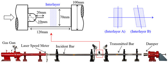
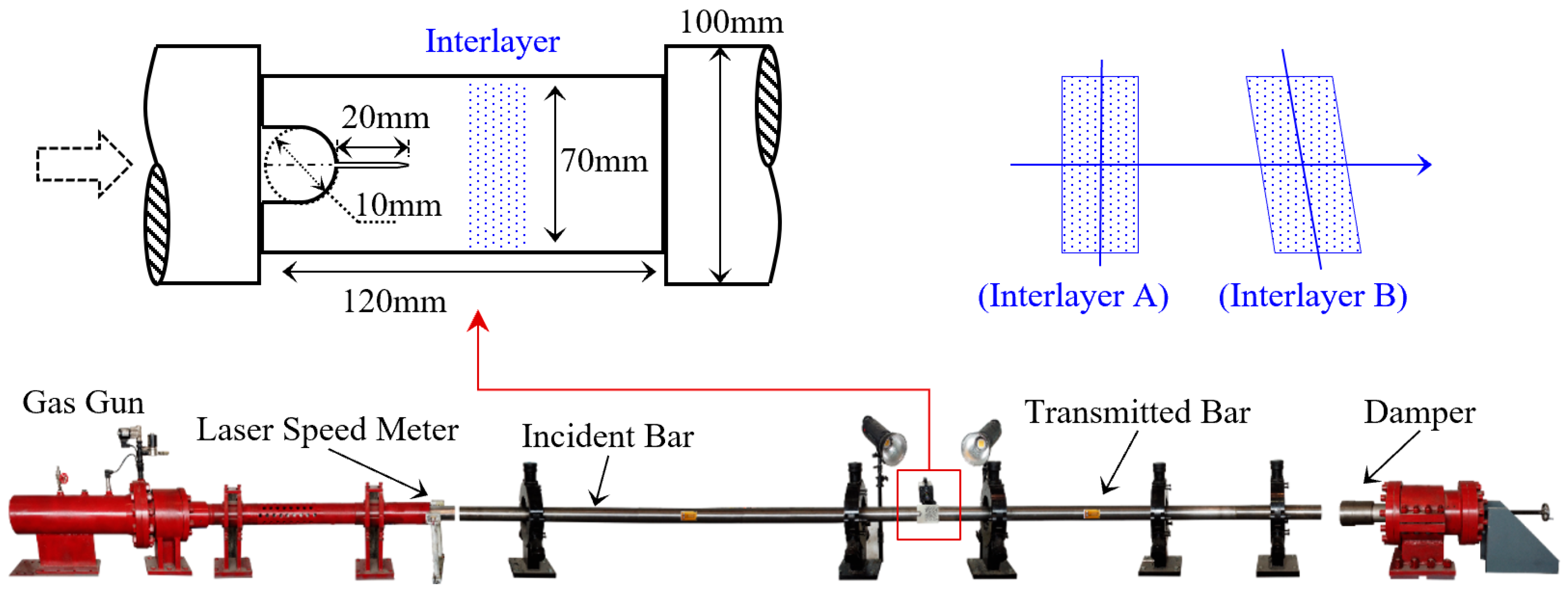
Based on the distinct geological conditions of the tunnel engineering background, a Soft–Hard Composite Single Cleavage Semi-Circle (SCSC) configuration was designed to mimic the layered rock mass. The SCSC geometry was explicitly selected because its pre-fabricated notch and semi-circular hole can stably guide the initiation and propagation of a pure Mode I crack under impact loading, which is essential for precisely decoupling the interaction between the advancing macroscopic crack and the targeted weak interlayer [28]. Two typical interlayer inclination angles were selected, as shown in Figure 1. Interlayer A is perpendicular to the horizontal axis of the specimen, while Interlayer B is rotated 15° counterclockwise relative to Interlayer A. The hard rock adopted is Yameng black sandstone from Sichuan Province, China, with a density of 2600 kg/m3, a Poisson’s ratio of 0.22, an elastic modulus of 16.67 GPa, and a tensile strength of 32 MPa. The interlayer is a rock-like material whose mix proportion is presented in Table 1; this material has a density of 1733 kg/m3, a Poisson’s ratio of 0.24, an elastic modulus of 6.72 GPa, and a tensile strength of 13 MPa. To prepare the specimens, two black sandstone blocks were cast together using the rock-like interlayer material and cured until they reached standard strength, after which impact tests were conducted. Three sets of repeat tests were conducted for each interlayer inclination. The specimens were named based on the inclination angle and test number. For example, the first specimen with a 0° inclination was designated as M0-1.
Figure 1.
Split Hopkinson pressure bar (SHPB) test system and specimen geometry.
Table 1.
Mass mix proportion of the rock-like interlayer material used in the composite specimens.
To prepare the composite specimens, a stringent quality control protocol was implemented. First, the interfaces of the black sandstone blocks were uniformly polished to a consistent roughness to standardise the mechanical interlocking effect. The blocks were then fixed in a high-precision mold to strictly ensure the 0° and 15° inclinations. The rock-like interlayer material was cast and subsequently compacted using a vibration table to eliminate interfacial air voids. Following demolding, all composite specimens were preserved in a standard curing environment (20 ± 2 °C, >95% humidity) for 28 days to reach their designated strength.
2.2. Split Hopkinson Pressure Bar (SHPB) and DIC System
Dynamic impact tests were conducted using a Split Hopkinson Pressure Bar (SHPB) system. The system comprises a striker bar (length 400 mm), an incident bar (3500 mm), and a transmission bar (2000 mm). All bars are made of 40CrMoV high-strength alloy steel with an elastic modulus of 212 GPa, a Poisson’s ratio of 0.25, and a density of 7860 kg/m3, as shown in Figure 1. A spindle-shaped striker was employed to generate a half-sine wave, ensuring a smooth loading pulse and facilitating dynamic force equilibrium. From Equation (1), the strain–time signals measured on the incident and transmission bars can be converted into a stress–time curve:
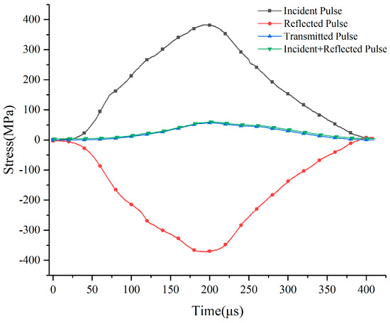
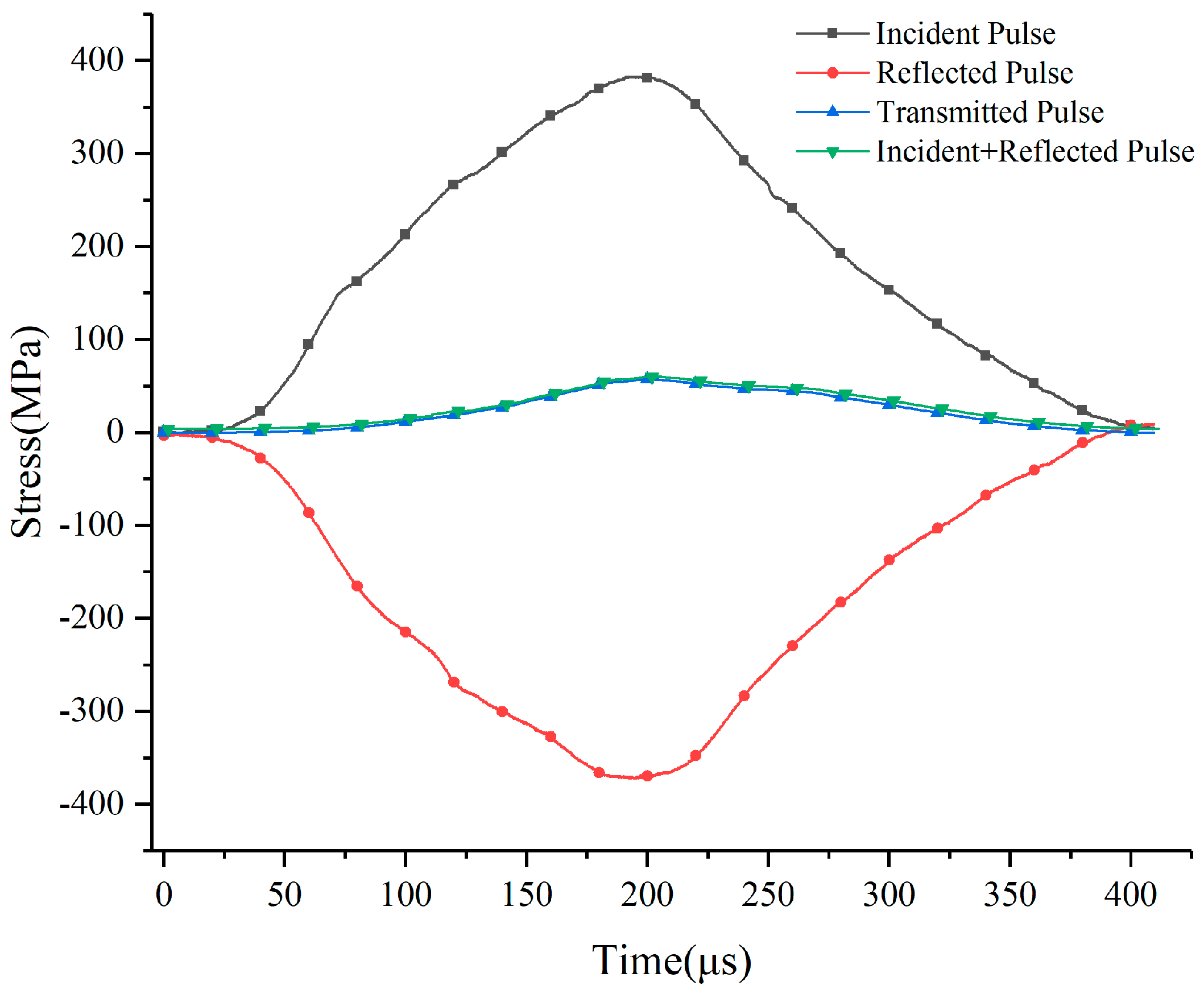
where E denotes elastic modulus, εi, εr and εt are the strains recorded by strain gauges adhering to the incident bar and transmission bar, σL is the stress applied to the left side of specimens and σR is the stress applied to the right side of specimens. As shown in Figure 2, the stress wave time-history curves recorded during the experiment are presented. A full-field Digital Image Correlation (DIC) analysis method was employed in the impact test. A high-speed camera was used to capture the failure process of the specimen in real time. Subsequently, the DIC analysis technique was applied to compute the full-field displacement and strain fields of the specimen [34]. This approach enables a detailed investigation of the joint propagation behavior under dynamic disturbance, providing quantitative insights into the evolution of deformation and failure mechanisms during impact loading.
Figure 2.
Stress–time curves recorded in the impact test.
It is important to objectively state the inherent measurement uncertainties within this experimental framework. For the SHPB system, residual interfacial friction between the rock specimen and the elastic bars can partially restrict transverse deformation. To mitigate this and minimize stress wave dispersion, a thin layer of lubricant was applied to the contact surfaces, and a spindle-shaped striker was strictly used to generate a smooth, half-sine incident wave, ensuring early dynamic force equilibrium. For the DIC measurements, uncertainties primarily originate from temporal–spatial resolution limits and out-of-plane motion. While the ultra-high frame rate of 120,000 fps provides an 8.3 μs interval, a rapidly propagating crack (>200 m/s) still advances across multiple pixels between frames, meaning the extracted velocities represent high-fidelity time-averaged approximations. Furthermore, as 2D-DIC assumes planar deformation, microscopic out-of-plane bulging during the catastrophic fracture may introduce minor artificial strain noise. Despite these inherent uncertainties, stringent quality control and parallel validation confirm that these systematic errors do not affect the fundamental validity of the observed crack arrest and dynamic shielding mechanisms.
3. Experimental Results of Dynamic Crack Propagation
3.1. Failure Mode
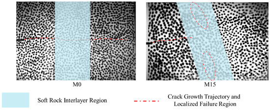
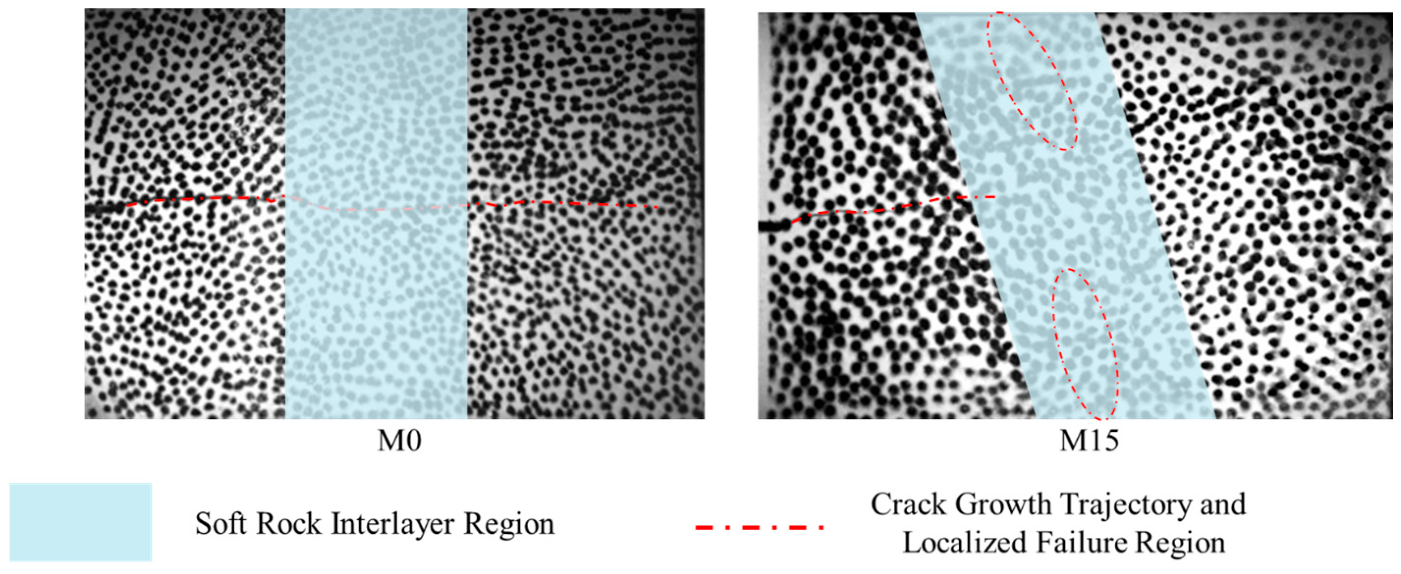
As shown in Figure 3, the failure patterns of specimens with different interlayer inclinations are presented. For the M0-1 specimen, the crack propagates linearly toward the boundary of the weak interlayer, where it undergoes deflection upon reaching the interface. Subsequently, the crack penetrates the interface and continues to propagate in a linear trajectory until reaching the bottom of the specimen. For the M15-1 specimen, after crack initiation, it deflects upward by approximately 8°. Subsequently, the crack exhibits a crack-arresting effect at the interface, failing to penetrate through. Instead, a localized damage zone emerges along the right boundary of the weak interlayer, as shown in the red circle area in Figure 3, indicating that the inclined interlayer configuration significantly alters the crack propagation behavior and failure mechanism.
Figure 3.
Failure patterns of specimens with different interlayer inclination angles.
3.2. Evolution of Crack Propagation Behavior Based on DIC Technique
Due to the difficulty of accurately identifying microscopic crack initiation through high-speed imaging, a reasonable crack initiation threshold was established based on the DIC strain field results to precisely locate and track the crack tip, the strain threshold of 1% was set as the criterion for crack initiation, as shown in Figure 4. A high-speed camera with a frame rate of 120,000 frames per second was employed, enabling the capture of crack growth evolution at intervals of 8.3 μs.
Figure 4.
Evolution of crack tip position using a 1% strain threshold (Example: M0-1 specimen).
When the strain gauge positioned at the midpoint of the incident bar in the SHPB system detects a stress wave, it sends a voltage signal to the ultra-dynamic strain amplifier, which then triggers the high-speed camera shutter to begin recording. This setup allows for a consistent standard to be used for calibrating the crack initiation time for each specimen. The average crack initiation time for the M0 specimen is 27.67 μs, while that for the M15 specimen is 41.5 μs. From the perspective of stress wave reflection–transmission mechanisms at the interlayer interface, the inclination angle of the weak interlayer influences the incident characteristics of stress waves and the distribution of stress concentration, thereby altering the crack initiation time. In the M0 specimen, the impact wave exhibits normal incidence, generating stronger normal reflections at the interface. This leads to higher tensile stress peaks near the pre-existing crack tip, promoting earlier crack initiation. Conversely, in the M15 specimen, the incident wave undergoes oblique transmission and shear wave conversion, resulting in a weaker normal tensile stress amplitude compared to the perpendicular incidence case. Consequently, the crack initiation time is delayed in this configuration.
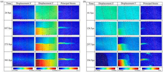
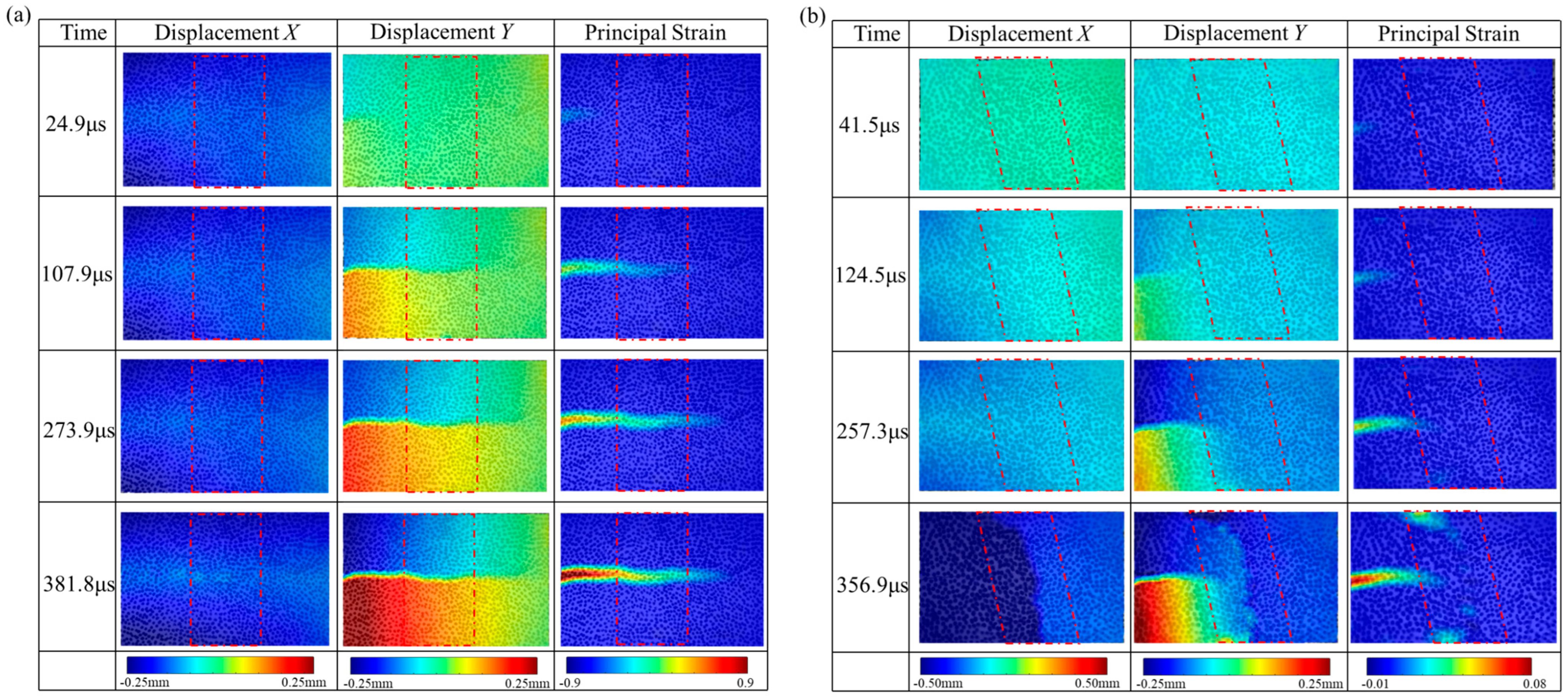
After performing DIC analysis, the full-field displacement and strain fields during the crack propagation process were obtained, as shown in Figure 5. The results indicate that the inclination of the weak interlayer has a significant impact on crack propagation behavior. For the M0-1 specimen, both the Y-direction displacement field and the principal strain field reveal that the crack initiates in the rock region and propagates straight through the interlayer, maintaining characteristics of a Mode I crack as it extends to the bottom of the specimen.
Figure 5.
Crack propagation evolution in specimens with different interlayer inclination angles (The red box represents the weak layer position): (a) displacement and strain evolution results of the M0-1 specimen; (b) displacement and strain evolution results of the M15-1 specimen.
In contrast, the M15-1 specimen exhibits a markedly different crack propagation response. From the X-direction displacement field at t = 356.9 μs, it is observed that the left half of the specimen displaces 0.12 mm more than the right half, indicating the formation of a compressive zone within the interlayer. The Y-direction displacement field further reveals a vertical displacement mismatch across the weak interlayer. Additionally, the principal strain contours show that beyond the propagation of the pre-existing crack, a localized damage band forms within the interlayer itself. This suggests that once the crack arrests at the weak interlayer, the energy carried by the stress wave is no longer dissipated through crack propagation and instead accumulates within the specimen. Given the lower strength of the interlayer material, damage localizes within this region, forming a compression-induced failure zone. These observations demonstrate that the presence and orientation of weak interlayers can fundamentally alter the failure mechanism, by redirecting or halting crack propagation and localizing energy-induced damage within the interlayer.
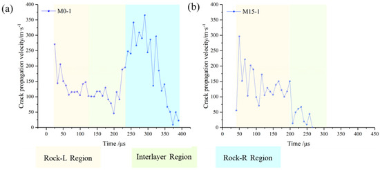
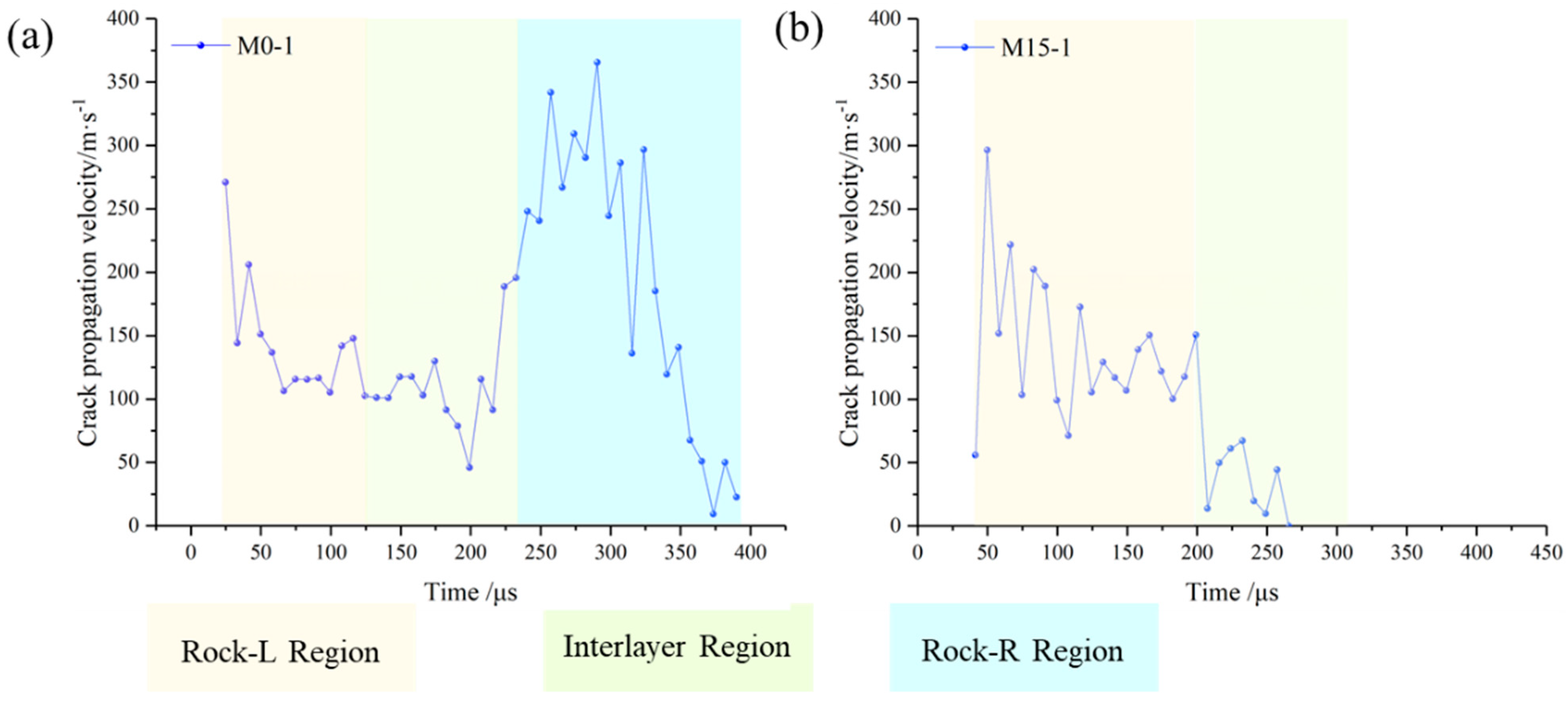
As shown in Figure 6, the influence of soft interlayer inclination on crack propagation velocity (CPV) is illustrated. For the M0 specimen, the crack initiates with a high velocity in the left rock region, followed by a gradual deceleration as it approaches the interlayer. The CPV reaches its minimum within the interlayer. After passing through the interlayer, the CPV increases rapidly and eventually decreases to zero as the crack propagation completes. In contrast, for the M15 specimen, the CPV initially increases and then decreases within the left rock region. Once the crack enters the interlayer, the velocity drops sharply and ultimately results in crack arrest within the interlayer zone.
Figure 6.
Crack propagation velocity with different interlayer inclination angle: (a) M0-1 specimen; (b) M15-1 specimen. (Note: Rock-L represents the incident-side hard rock region where the stress wave enters; Interlayer denotes the weak interlayer zone; Rock-R indicates the transmitted-side hard rock region behind the interlayer).
To further quantify this behavior, the average propagation velocity was calculated for three distinct regions: (1) within the soft interlayer, (2) the left rock region adjacent to the interlayer, and (3) the right rock region beyond the interlayer (Table 2). Although the inclination of the soft interlayer affects the crack initiation time, it has little influence on the pre-interlayer crack velocity. The average CPV before entering the interlayer is 141.11 m/s for M0 and 144.24 m/s for M15. However, once the crack enters the interlayer, the propagation velocity significantly decreases. For the M0 specimen, the average CPV within the interlayer is 108.46 m/s, representing a 23.1% reduction compared to the left rock region. For the M15 specimen, where crack arrest occurs within the interlayer, the average CPV drops to 35.30 m/s, a 75.5% reduction compared to the left rock region and a 67.6% decrease relative to the M0 specimen’s interlayer CPV. Moreover, for the M0 specimen, after the crack passes through the interlayer, the CPV increases to 211.68 m/s, which is 50.0% higher than in the left rock region and 95.2% higher than within the interlayer.
Table 2.
Average crack propagation velocity in different regions.
4. Numerical Analysis of Stress Wave Propagation and Failure Mechanism
While the SHPB experiments and DIC analysis provided macroscopic observations of crack propagation and surface strain evolution, the internal dynamic interaction between stress waves and the inclined weak interlayer remains difficult to observe directly. To bridge this gap, the calibrated 2D numerical model was used to visualize stress-wave propagation within the rock mass. This section analyzes the evolution of the stress field and elucidates the mechanical origins of the distinct failure modes observed in M0 and M15 specimens.
4.1. Numerical Model Establishment
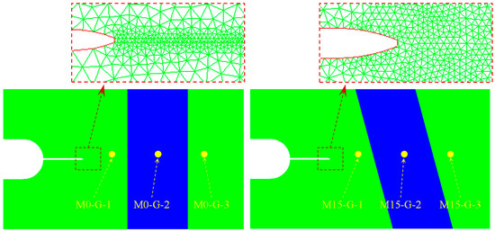
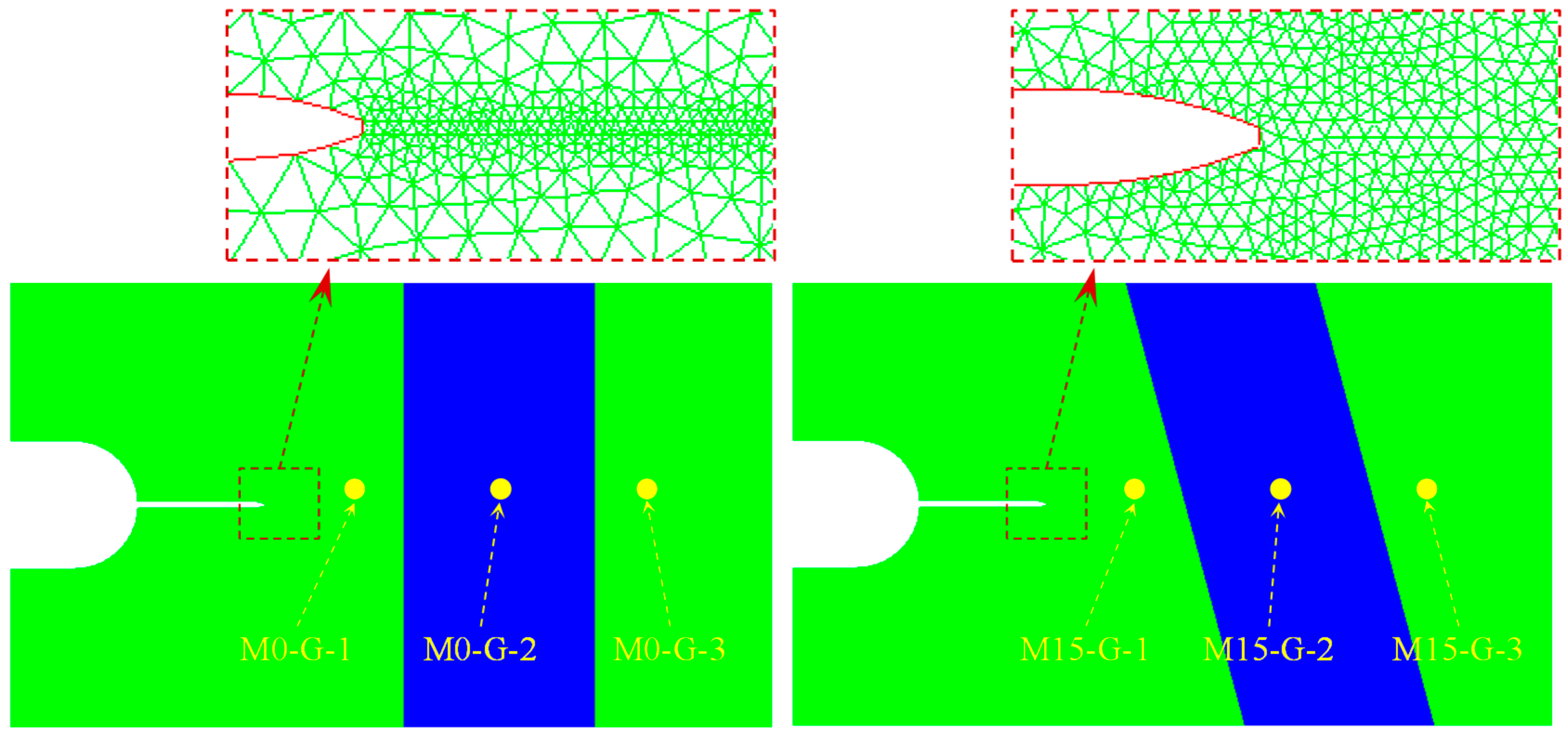
A 2D numerical model was established in Ansys 19.2-AUTODYN to serve as a digital replica of the SCSC specimens, as shown in Figure 7, enabling comprehensive visualization of the interaction between stress waves and the rock structure, as well as the resulting fracture patterns. The tensile crack softening (TCS) model was employed to characterize the dynamic mechanical behavior and damage of the sandstone and weak interlayers [32], with a fracture energy of 193 J/m3 for the sandstone and 80 J/m3 for the weak interlayers. This model accounts for crack softening, which is critical for accurately simulating crack initiation and subsequent propagation under impact loading. Material parameters were calibrated against both static and dynamic experimental data to ensure simulation fidelity.
Figure 7.
Numerical model layout and crack tip grid.
To ensure the fidelity of the numerical simulation, a rigorous two-step calibration workflow was executed for the Tensile Crack Softening (TCS) model prior to the detailed failure analysis. First, the baseline physical and mechanical properties of the sandstone and the rock-like interlayer (including density, elastic modulus, Poisson’s ratio, and static tensile strength) were directly imported from the standard static laboratory tests previously detailed in Section 2.1. Secondly, the dynamic fracture parameters, specifically the fracture energy, were calibrated through a trial-and-error back-analysis. By iteratively adjusting the fracture energy in the AUTODYN model and comparing the outputs against the actual SHPB impact results, the calibration was finalized only when the simulated macroscopic failure trajectories and crack arrest behaviors highly matched the experimental high-speed DIC observations. Through this physically grounded calibration process, the dynamic fracture energies were determined to be 193 J/m3 for the sandstone and 80 J/m3 for the weak interlayers.
The numerical model strictly follows the geometric dimensions of the M0-1 and M15-1 specimens. To ensure the reliability of the fracture simulation, a preliminary mesh sensitivity analysis was conducted. Mesh sizes of 0.5 mm, 0.2 mm, and 0.1 mm were evaluated. The analysis indicated that a 0.5 mm mesh induced numerical dispersion and failed to capture the fine localized shear bands, whereas a 0.1 mm mesh dramatically increased computational cost without significantly altering the crack trajectory. Consequently, a refined mesh with a size of 0.2 mm was strictly deployed in the critical central region—including the weak interlayer, the pre-fabricated notch, and their vicinity—to precisely resolve the stress wave diffraction, mode conversion, and crack tip singularity. A progressive transition mesh was applied to smoothly connect this high-resolution zone with coarser peripheral regions, perfectly balancing computational efficiency and fidelity.
Regarding the boundary conditions, to faithfully replicate the physical unconfined state of the SCSC specimen in the SHPB apparatus, the top and bottom lateral boundaries of the 2D model were defined as free surfaces. For the dynamic loading, the exact stress wave time-history curves obtained from the experiments (via Equation (1)) were applied directly to the incident and transmission faces as time-dependent stress boundaries, ensuring absolute loading consistency between the digital replica and the physical test.
4.2. Model Validation
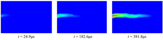
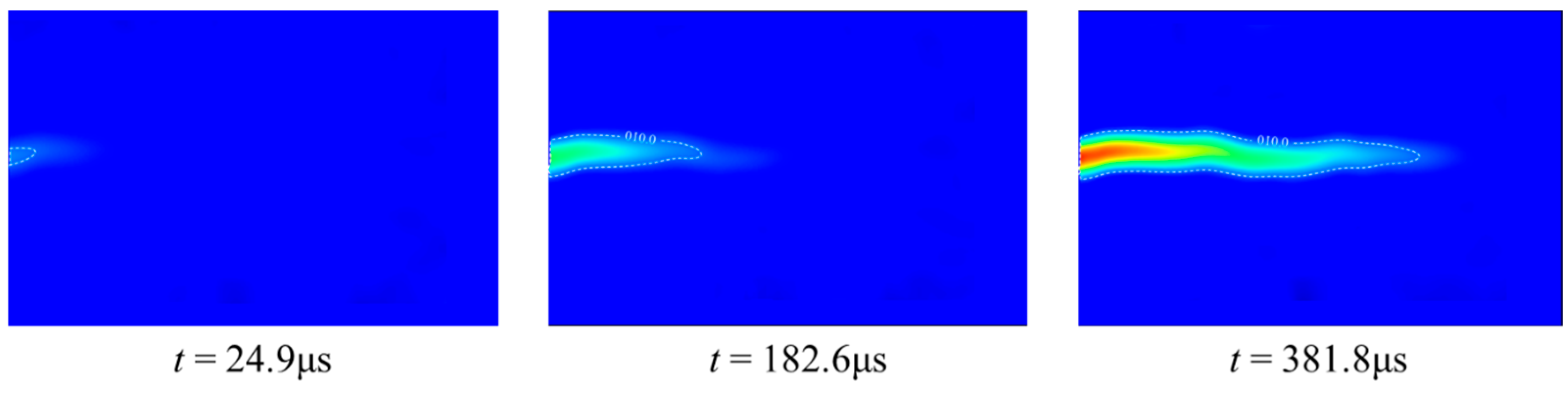
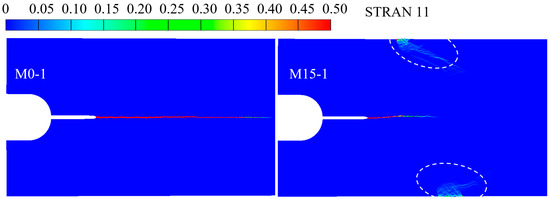
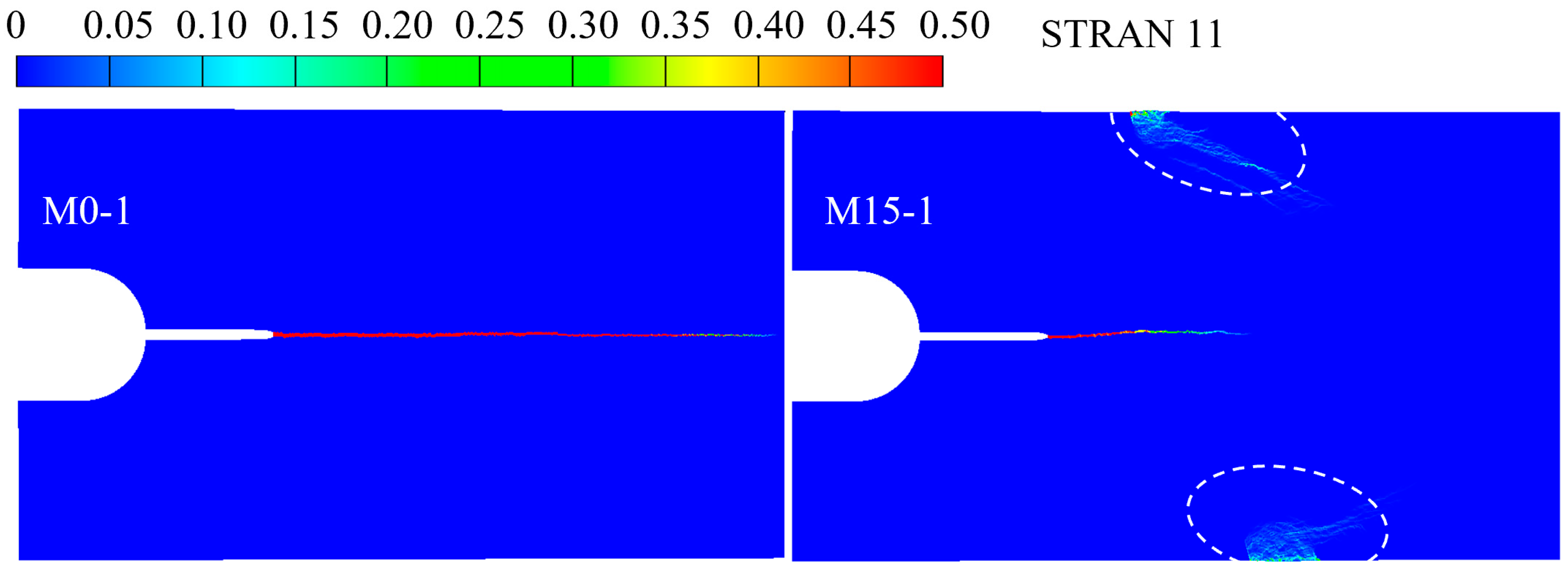
To ensure the reliability of the numerical investigation, the simulated failure patterns were first compared with the experimental results. As shown in Figure 8, the numerical model successfully reproduces the key fracture characteristics. For the M0-1 specimen, the simulation shows a main crack penetrating directly through the vertical interlayer, consistent with the straight crack path observed in the experiment. For the M15-1 specimen, the numerical result accurately captures the crack deflection and the subsequent arrest phenomenon within the weak interlayer. An obvious strain concentration band is observed in the weak interlayer of the numerical model, as shown in Figure 8 (dashed circle area), indicating the development of localized large deformation in this region. The high consistency between the simulated damage zone and the experimental fracture morphology validates the accuracy of the selected constitutive models and parameters.
Figure 8.
Numerical strain contours for both M0-1 and M15-1.
4.3. Dynamic Evolution of Strain Field and Failure Modes
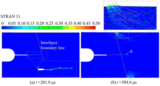
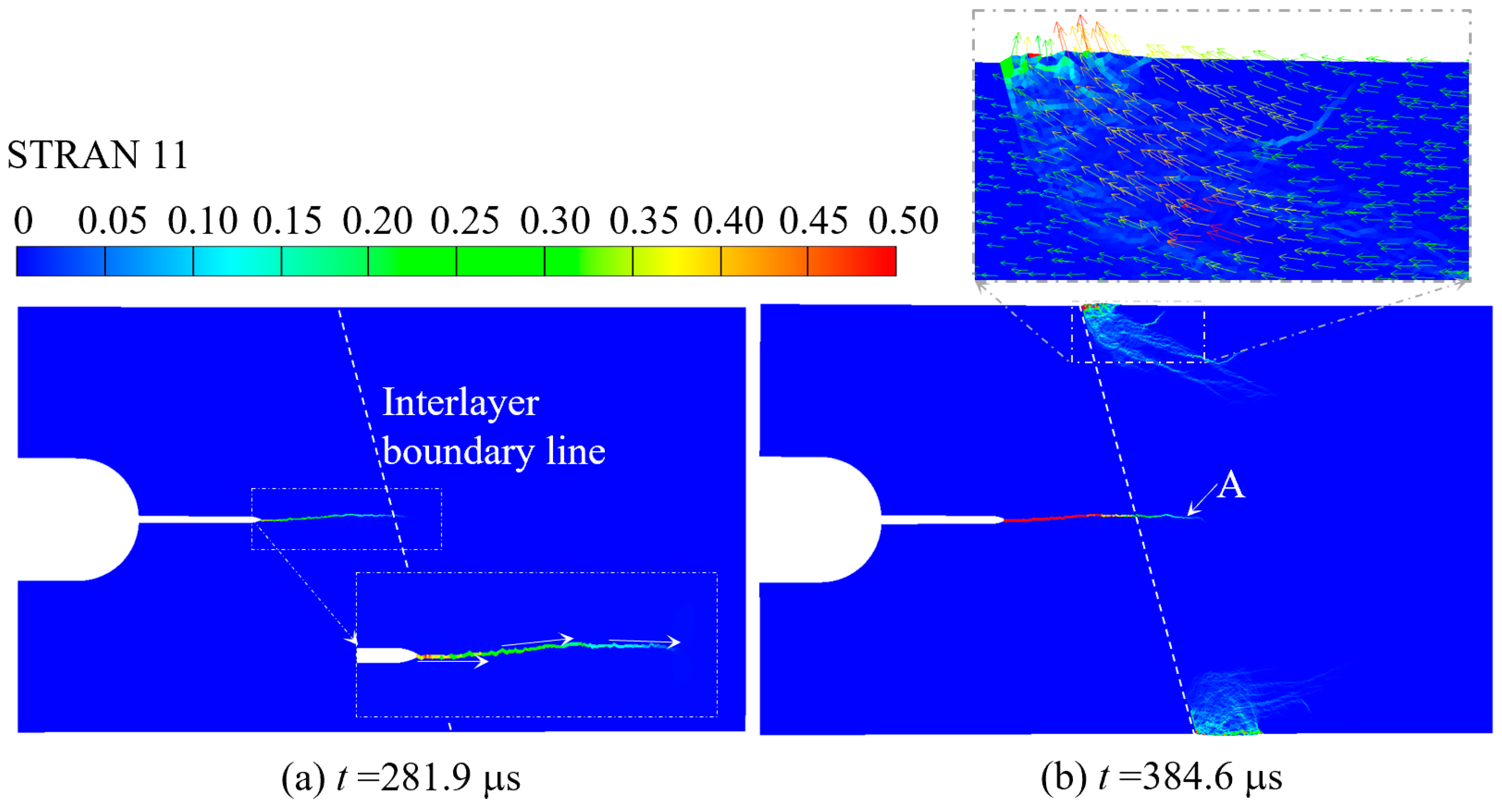
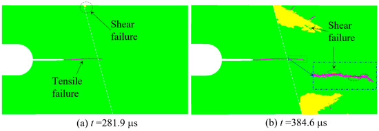
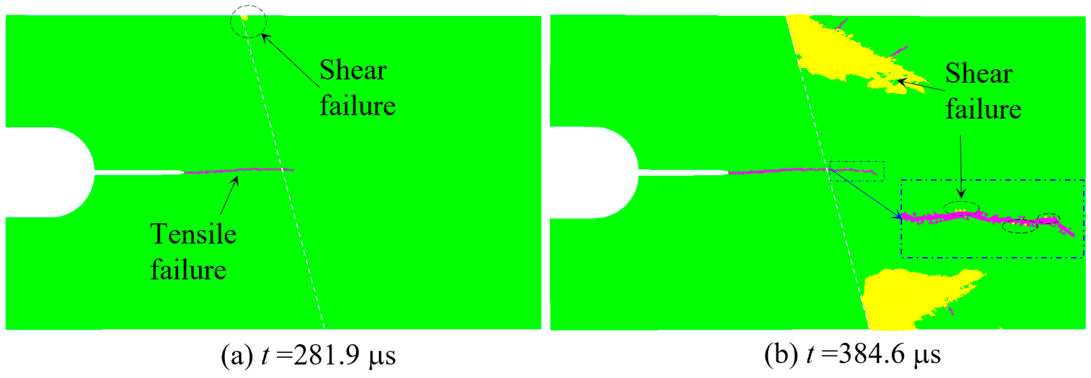
To visualize the real-time interaction between the propagating crack and the inclined weak interlayer, the evolution of the maximum principal strain field and the corresponding failure modes of the M15 specimen are analyzed. Figure 9 presents the comparative results at two critical time steps: before the crack reaches the interface and after it enters the interlayer. The strain evolution reveals a distinct transition in fracturing behavior. Before t = 281.9 μs, the crack is propagating within the hard sandstone matrix. The maximum principal strain is highly concentrated at the crack tip, exhibiting a typical symmetrical Mode-I tensile fracture. The surrounding rock mass remains relatively undisturbed, indicating that the energy is efficiently driving the crack extension. It can be clearly observed from Figure 9a that the crack initially propagates horizontally and then deflects upward. This is because the stress wave reflects as a tensile wave when encountering the interlayer interface, guiding the upward propagation of the crack. As the crack propagates and approaches the interface, it is disturbed by the stress wave and turns to propagate horizontally. After the crack penetrates the interface and enters the weak interlayer, shear failure initiates in the interlayer, as shown in Figure 10a, and this failure mode is clearly visible in the upper left corner of the interlayer. The entire interlayer exhibits an extrusion effect in its upper and lower edge regions due to the disturbance of the stress wave, and this particle motion trend can be identified from the magnified view of the particle motion vector in Figure 9b. At this time, the shear deformation of the interlayer inhibits the propagation of the original tensile crack and induces a distinct downward propagation tendency, as indicated by Point A in Figure 9b.
Figure 9.
Dynamic evolution of the principal strain for the M15-1.
Figure 10.
Evolution of dynamic failure modes (tensile and shear) for the M15-1.
The failure modes in Figure 10 provide direct evidence for the arrest mechanism of the main crack. In the early stage, the fracture path is almost entirely marked by tensile failure (indicated by purple elements), which confirms that crack initiation and propagation in sandstone are driven by the tensile stress of the incident wave. Drastic changes occur when the crack interacts with the weak interlayer: extensive shear failure (indicated by yellow regions) appears along the interlayer boundaries, and a shear failure zone also initiates at the tip of the main crack simultaneously. The occurrence of shear failure verifies that the inclined interface induces a strong mode conversion, which decomposes the incident compressive pulse into shear stresses exceeding the shear strength of the weak interlayer. Extensive plastic shear deformation consumes a large portion of the stress wave energy, thereby depriving the crack tip of the tensile driving force required for further propagation and resulting in the observed crack arrest.
Furthermore, these numerical findings provide a microscopic mechanical explanation for the macroscopic observations in the DIC experiments. The localized compressive and shear damage bands observed in the DIC principal strain contours, as shown in Figure 5b, correspond exactly to the extensive shear failure elements identified in the AUTODYN simulation, as shown in Figure 10b. This cross-validation confirms that the abrupt drop in crack propagation velocity observed in Section 3 is not merely a geometric delay, but a direct consequence of impact energy being intensely consumed by the wave-mode-conversion-induced plastic shear yielding at the inclined interface.
4.4. Failure Mechanism Induced by Stress Wave Reflection and Transmission
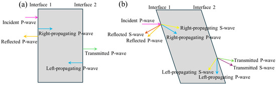
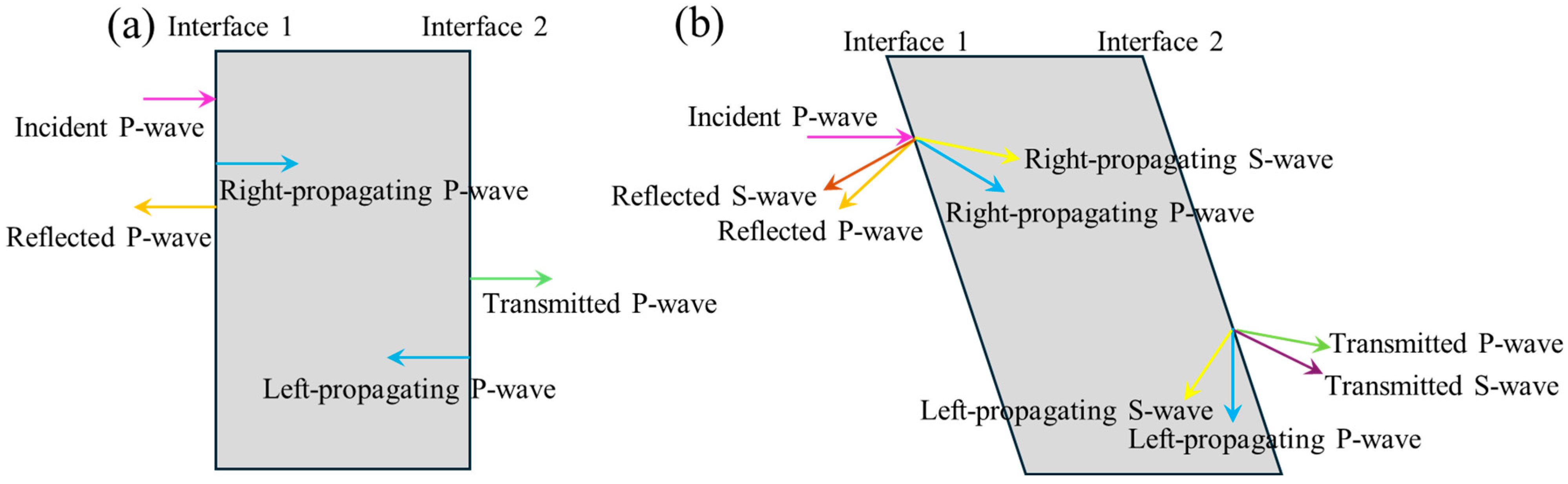
This contrast in crack resistance between hard rock and the weak interlayer governs the variation in crack propagation velocity. Moreover, the inclination of the interlayer further alters the overall failure mode of the specimen. As shown in Figure 11, the reflection and transmission of stress waves at the interlayer interfaces vary with the inclination angle. For the M0 specimen, the incident P-wave enters the interlayer and generates left- and right-traveling P-waves that remain normal to the interface, resulting in minimal influence on the crack path and failure mode. However, in the M15 specimen, the wave interaction becomes more complex due to the inclined interfaces. At the first interface, the reflected tensile P-wave arrives at the crack tip sequentially from top to bottom due to the tilt, promoting upward deflection of the crack. Additionally, left- and right-traveling S-waves and a right-traveling P-wave are generated. Similar reflection–transmission behavior occurs at the second interface. Under the influence of the shear waves, the weaker interlayer becomes more susceptible to shear dislocation, leading to localized concentrated failure. This localized failure consumes the energy carried by the stress wave and creates new free surfaces, which inhibit further crack growth, resulting in crack arrest. From the perspective of rock dynamics, this reflection–transmission behavior is fundamentally governed by the effective acoustic impedance mismatch at the soft–hard interface. In the orthogonal M0 configuration, the incidence angle aligns with the maximum compressional transmission coefficient, enabling the tensile driving force to readily cross the boundary. However, the M15 inclination dynamically alters the effective incidence angle. This geometric shift not only triggers the aforementioned mode conversion but also significantly alters the energy partitioning ratio at the boundary, forcing a larger fraction of the incident wave energy to be reflected or trapped within the weak interlayer.
Figure 11.
Influence of weak interlayers with different inclination angles on incident stress wave behavior: (a) Orthogonal incidence; (b) Oblique incidence.
4.5. The Mechanism of the Dynamic Shielding Effect
The mechanism of crack arrest in the inclined interlayer can be fundamentally attributed to the mode conversion of stress waves and the resulting shear localization. Unlike the M0 case, where normal stress dominates, the M15 configuration results in a significant accumulation of shear stress within the weak interlayer material. The numerical results show that the “damage band” in the interlayer is coincident with the peak shear stress region. This suggests that the energy of the incident wave is largely consumed by the shear dislocation and plastic deformation of the weak interlayer material. Consequently, the tensile stress required to drive the crack tip forward is severely attenuated. The combination of stress-wave dispersion (due to oblique reflection) and energy dissipation via shear failure (induced by mode conversion) ultimately leads to crack arrest in an inclined layered rock mass.
By synthesizing the experimental and numerical findings, the mechanical essence of this crack arrest phenomenon can be formally conceptualized as a Dynamic Shielding Effect. Because the incident impact energy is overwhelmingly converted into shear modes and exhausted through localized plastic deformation at the inclined interface, the weak interlayer effectively acts as a dynamic shield. It systematically starves the crack tip of its driving force and shields the surrounding hard rock strata behind it from further impact damage. This micro-to-macro shielding mechanism serves as the crucial physical bridge connecting the localized fracture behavior to the macroscopic blasting outcomes, which will be further discussed in the context of engineering optimization.
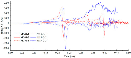
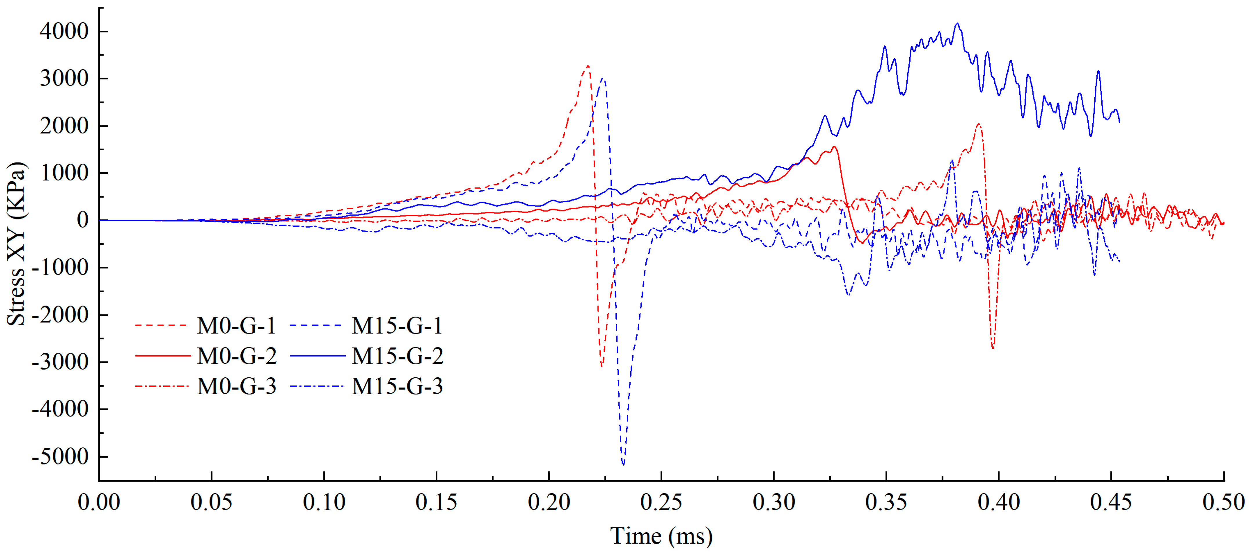
To quantitatively elucidate the intrinsic mechanical mechanisms of wave mode conversion and the dynamic shielding effect, the histories of dynamic shear stress (Stress XY) were extracted for the M0-1 and M15-1 specimens at three critical locations, as shown in Figure 12.
Figure 12.
Comparison of shear stress at different monitoring points for the M0-1 and M15-1 specimens.
For the M0-1 specimen, since the incident wave strikes the interface perpendicularly, the stress wave primarily propagates in a straight line as P-waves, with little macroscopic wave-mode conversion. Consequently, the shear stress levels remain relatively low both within the weak interlayer (M0-G-2) and in the surrounding hard rock regions (M0-G-1, M0-G-3). They manifest merely as brief, low-amplitude oscillations associated with the transient tearing of the primary crack and localized Poisson effects.
In stark contrast, the M15-1 specimen fundamentally alters the evolution of the localized stress field. Firstly, the monitoring point within the weak interlayer (M15-G-2) exhibits a pronounced and sustained shear-stress plateau after 0.25 ms. This surging shear stress provides direct quantitative evidence for wave mode conversion at the microscopic level: the inclined geometric interface forces the incident P-wave to decompose, generating a significant shear component. This directly induces the extensive plastic shear yielding observed in the interlayer material, which aligns perfectly with the failure modes in Figure 11. Simultaneously, due to the severe wave impedance mismatch and mode conversion, a large portion of the energy fails to transmit forward and is forcibly reflected. This results in an extremely violent shear stress concentration and oscillation in the hard rock ahead of the interlayer (M15-1), with an amplitude far exceeding that of the M0 configuration.
Most critically, for the M15-1 specimen, the shear stress transmitted into the hard rock behind the interlayer (M15-G-3) is almost completely attenuated, appearing as a flat line close to zero on the time-history curve. This sharp reduction in transmitted stress constitutes the definitive quantitative proof of the Dynamic Shielding Effect. Because the incident wave energy is massively dissipated by severe shear deformation within the weak interlayer and partially reflected at the interface, the rock mass behind the fault is effectively isolated and protected, forming a distinct macroscopic “energy shadow zone”. The severing of this energy transmission path fundamentally explains the mechanical root cause of the primary crack losing its driving force at the inclined interlayer and ultimately arresting.
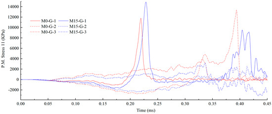
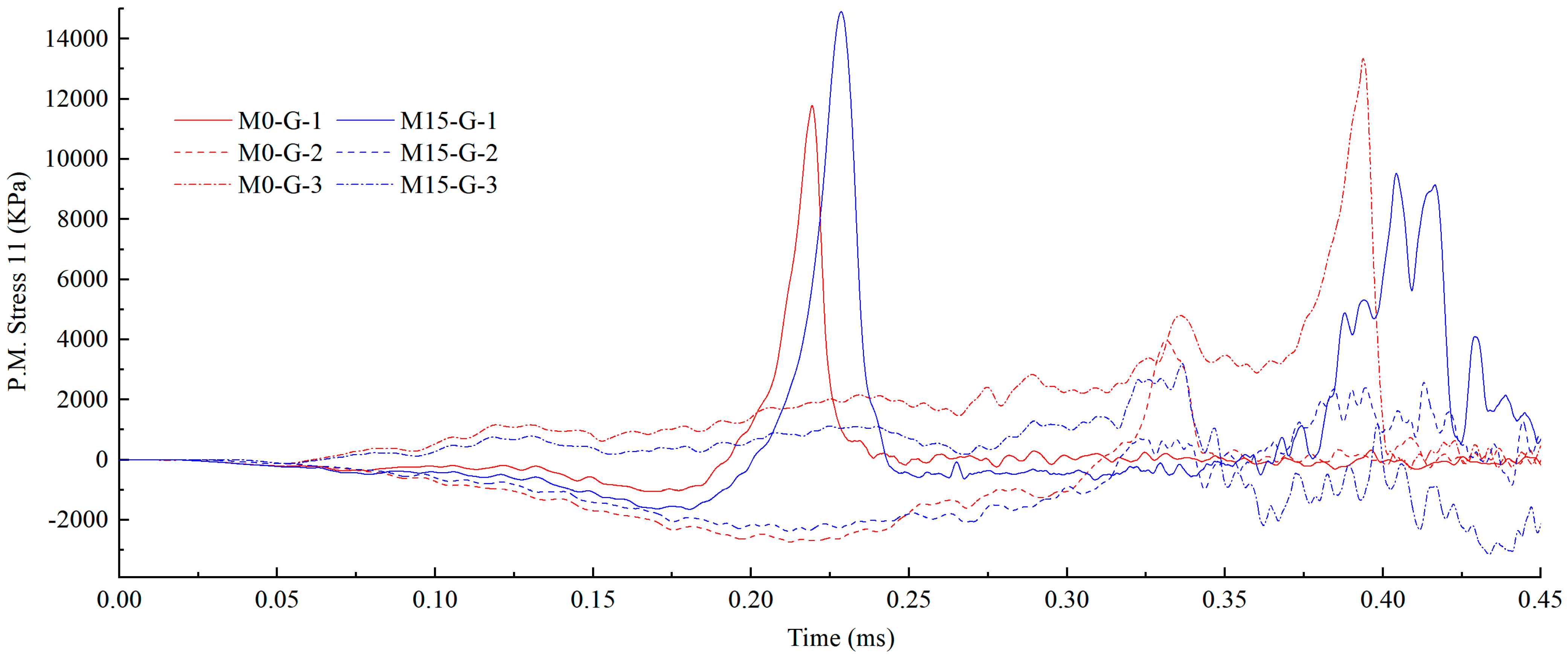
To fundamentally elucidate the mechanical root cause of why the primary crack loses its tensile driving force and permanently arrests, the time-history curves of the maximum principal stress at the identical monitoring points were extracted, as shown in Figure 13. In rock dynamic fracture mechanics, the positive maximum principal stress directly governs the Mode I (tensile) failure behavior of the rock matrix.
Figure 13.
Comparison of maximum principal stress at different monitoring points for the M0-1 and M15-1 specimens.
For the M0-1 specimen, the stress wave transmits efficiently across the interfaces. Consequently, the transmitted hard rock (M0-G-3) receives a massive maximum principal stress peak. This powerful tensile pulse provides sufficient and continuous driving force for the crack tip to easily penetrate the vertical weak interlayer and completely split the specimen.
In stark contrast, for the M15-1 specimen, the maximum principal stress transmitted to the hard rock behind the interlayer (M15-G-3) experiences a catastrophic attenuation. The stress curve becomes nearly flat, with its peak value dropping drastically, showing an almost 90% reduction. Because the vast majority of the incident wave energy is forced to convert into shear modes and is subsequently dissipated by the severe material fracture within the weak interlayer, the remaining transmitted tensile stress is thoroughly depleted. Quantitative evidence of the ‘Dynamic Shielding Effect’ is provided by this significant stress reduction: the threshold tensile stress required for dynamic fracture cannot be accumulated by the shielded rock mass, resulting in the crack tip being deprived of its propagation capability.
5. Engineering Significance of Mining Blasting Optimization
The experimental and numerical results of this study provide fundamental insights for the optimization of drilling and blasting operations in complex geological environments. Split Hopkinson Pressure Bar (SHPB) tests adopt pre-fabricated cracks to quantitatively decouple the influence of inclined weak interlayers on crack propagation. However, in mining engineering, explosion-induced stress waves and the resulting crack network radiate outward in a complex, multi-directional pattern. Therefore, it is almost impossible to achieve complete normal incidence at 0° between the radiating wavefront and the geological weak interlayer. Accordingly, the core value of this study lies in identifying the “shielding effect” of low-angle weak interlayers.
5.1. Quantitative Blasting Optimization Strategies
As demonstrated by the M15 specimen, when the direction of the dynamic stress wave is at an angle to the weak interlayer, severe mode conversion of the stress wave occurs, where the P-wave is converted into a mixture of P-waves and S-waves. The subsequent plastic shear deformation acts as a substantial energy dissipation zone. Macroscopic cracks are arrested at the interface, with their propagation velocity reduced by 75.5%. In actual blasting scenarios, this mechanism indicates that the weak interlayer essentially serves as a dynamic barrier, preventing further penetration of explosion energy. Consequently, an “energy shadow zone” is formed in the rock mass behind the inclined fault, where the lack of tensile driving force leads to poor fragmentation and frequent occurrence of oversized boulders.
With the recognition of this shielding mechanism, mining engineers can proactively optimize blasting designs. The blasting strategy should focus on spatial compensation and wavefront management, rather than unrealistically aligning boreholes to achieve 0° incidence angle. The specific measures are as follows:
- (1)
- Spatial Compensation via Auxiliary Boreholes
During the blasting design stage, once an inclined weak interlayer is identified through geological logging, engineers must predict the formation of an energy shadow zone behind it. To prevent the formation of oversized boulders, the standard borehole spacing must be adjusted, and auxiliary boreholes should be deployed directly within the predicted shadow zone. This ensures that the rock mass shielded by the interlayer can be effectively fragmented by receiving localized explosion energy, independent of the stress waves blocked by the fault. Based on the quantitative finding that the transmitted maximum principal stress is attenuated by approximately 90% upon crossing a 15° inclined interlayer, the effective blasting radius is heavily truncated. Consequently, standard empirical hole spacing is entirely inadequate for the rock mass behind the fault. It is recommended that the burden and spacing of auxiliary blastholes deployed within this predicted shadow zone be reduced by 30% to 50% to compensate for the extreme energy dissipation.
- (2)
- Temporal Optimization via Delay Timing
Although individual crack trajectories are stochastic, the macroscopic stress wavefront generated by multi-hole blasting can be shaped using precision electronic delay detonators. By initiating blastholes in a strategically designed sequence, the superimposed stress wavefront can be regulated. Engineers can adopt this technique to guide the primary wavefront to impact the shielding interlayer at a more normal angle, thereby minimizing shear-induced energy dissipation. By synchronizing the delay times of adjacent holes using high-precision electronic detonators, the resulting superimposed wavefront can be systematically steered to impact the shielding interlayer at an angle closer to 0° (normal incidence). This spatial-temporal adjustment actively avoids the 10–20° critical inclination range, thereby suppressing the P-to-S wave mode conversion and improving the overall fragmentation efficiency.
5.2. Applicable Boundaries and Limitations
To prevent the blind application of these research findings in diverse mining environments, the applicable boundaries of the “Dynamic Shielding Effect” must be explicitly defined:
- (1)
- Lithological and Geometric Constraints: The proposed crack arrest mechanism is rooted in the acoustic impedance mismatch and the volume of plastic shear yielding. Therefore, the conclusions are most applicable to distinct soft–hard composite rock masses. If the physical discrepancies between strata are minimal, or if the weak interlayer is merely a tightly closed microscopic joint lacking sufficient thickness to accommodate large-scale shear deformation, the shielding effect will be greatly weakened.
- (2)
- Influence of Deep In Situ Stress: The present physical model exclusively evaluates the transient dynamic response without the coupling of initial confining pressure. In deep underground engineering, the rock mass is subjected to high deep in situ stresses. Under typical 2D plane strain conditions where both radial and circumferential stresses are inherently compressive, the geological interfaces are tightly clamped. This initial high confinement enhances the dynamic shear strength of the weak interlayer, which resists the shear dislocation induced by oblique stress waves. Consequently, the dynamic shielding effect may be mitigated under high-geostress conditions. The current findings are highly reliable for shallow-to-medium depth excavations or stress-relieved zones, while further research incorporating coupled static-dynamic loads is required for deep-earth applications.
6. Conclusions
Based on the impact experiments utilizing the SHPB and DIC systems, combined with numerical simulations of stress wave propagation, this study elucidates the dynamic response of geological joints in layered rock masses. The results indicate that the inclination of the weak interlayer fundamentally alters the stress wave propagation path, velocity evolution, and the resulting failure mechanisms. The following specific conclusions are drawn:
- The geometrical orientation of the weak interlayer governs the fracture trajectory. For vertically aligned interlayers, the crack maintains a tensile-dominated straight path, successfully penetrating the “hard–soft–hard” structure. In contrast, inclined interlayers induce a distinct upward deflection of the crack path, ultimately leading to crack arrest within the weak interlayer.
- The barrier effect of the interlayer is quantitatively reflected in the CPV. In the vertical case, the CPV experiences a temporary reduction of approximately 23.1% within the interlayer before recovering to high speeds. Conversely, the inclined interlayer causes a catastrophic decay in velocity with a reduction of 75.5%, resulting in the complete cessation of propagation.
- Numerical analysis reveals that the crack arrest phenomenon in inclined layers is fundamentally driven by stress wave mode conversion. Unlike the normal incidence in vertical layers, the inclined interface decomposes the incident compressive P-wave into significant shear S-wave components, changing the local stress field.
- The induced shear waves trigger localized shear failure band within the weak interlayer. This process acts as a potent energy dissipation mechanism, consuming the stress wave energy and effectively depriving the crack tip of the tensile driving force required to penetrate the subsequent hard rock layer.
Author Contributions
Conceptualization, C.X. and Z.S.; methodology, C.X.; software, M.W.; validation, Z.S.; formal analysis, C.X. and Z.S.; investigation, Y.S.; resources, Y.H.; data curation, Y.S. and Y.H.; writing—original draft preparation, C.X. and Z.S.; writing—review and editing, M.W.; visualization, C.X.; supervision, C.X. and M.W.; project administration, M.W.; funding acquisition, C.X. All authors have read and agreed to the published version of the manuscript.
Funding
This research was funded by Sichuan Communication Surveying & Design Institute Co., Ltd. (Grant number 232023004), and Sichuan Science and Technology Program (Grant number 2026YFHZ0066).
Data Availability Statement
The data presented in this study are available on request from the corresponding authors due to data security.
Conflicts of Interest
Authors Chunhong Xiao and Zhongqiu Sun were employed by the company Sichuan Communication Surveying & Design Institute Co., Ltd. The remaining authors declare that the research was conducted in the absence of any commercial or financial relationships that could be construed as a potential conflict of interest. The authors declare that this study received funding from Sichuan Communication Surveying & Design Institute Co., Ltd. and Sichuan Science and Technology Program. The funder was not involved in the study design, collection, analysis, interpretation of data, the writing of this article or the decision to submit it for publication.
References
- Dehghan Banadaki, M.M.; Mohanty, B. Numerical Simulation of Stress Wave Induced Fractures in Rock. Int. J. Impact Eng. 2012, 40–41, 16–25. [Google Scholar] [CrossRef] [Scilit]
- Trivino, L.F.; Mohanty, B. Assessment of Crack Initiation and Propagation in Rock from Explosion-Induced Stress Waves and Gas Expansion by Cross-Hole Seismometry and FEM–DEM Method. Int. J. Rock Mech. Min. Sci. 2015, 77, 287–299. [Google Scholar] [CrossRef] [Scilit]
- Man, J.; Zhou, M.; Zhang, D.; Huang, H.; Chen, J. Face Stability Analysis of Circular Tunnels in Layered Rock Masses Using the Upper Bound Theorem. J. Rock Mech. Geotech. Eng. 2022, 14, 1836–1848. [Google Scholar] [CrossRef] [Scilit]
- Fan, L.; Shi, X.; Wang, M.; Yang, Q.; Chen, S. The Effects of Joint Spacing on Transmission Characteristics of Stress Waves through Layered Composite Rock Masses. Int. J. Numer. Anal. Met. 2024, 48, 822–836. [Google Scholar] [CrossRef] [Scilit]
- Wang, Z.; Zhu, Z.; Zhou, L.; Wang, M.; Ma, L.; Nie, F.; Shi, T. Dynamic Mechanical Properties and Failure Characteristics of Layered Composite Rock Containing a Tunnel-Shaped Hole. Theor. Appl. Fract. Mech. 2024, 129, 104217. [Google Scholar] [CrossRef] [Scilit]
- Wen, S.; Zhang, C.; Chang, Y.; Hu, P. Dynamic Compression Characteristics of Layered Rock Mass of Significant Strength Changes in Adjacent Layers. J. Rock Mech. Geotech. Eng. 2020, 12, 353–365. [Google Scholar] [CrossRef] [Scilit]
- Ding, X.; Niu, X.; Pei, Q.; Huang, S.; Zhang, Y.; Zhang, C. Stability of Large Underground Caverns Excavated in Layered Rock Masses with Steep Dip Angles: A Case Study. Bull. Eng. Geol. Environ. 2019, 78, 5101–5133. [Google Scholar] [CrossRef] [Scilit]
- Fortsakis, P.; Nikas, K.; Marinos, V.; Marinos, P. Anisotropic Behaviour of Stratified Rock Masses in Tunnelling. Eng. Geol. 2012, 141–142, 74–83. [Google Scholar] [CrossRef] [Scilit]
- Wang, P.; Ma, C.; Liu, C.; Liu, Q.; Fu, Y.; Cai, M. Anisotropic Behavior of Excavated Layered Rock Mass Subjected to Compression Considering the Joint Roughness. Bull. Eng. Geol. Environ. 2023, 82, 373. [Google Scholar] [CrossRef] [Scilit]
- Shu, Y.; Zhu, Z.; Wang, M.; Wang, F.; Ren, L.; Li, Y. A Modified JH2 Model with Improved Strength Model, Damage Evolution, and Equation of State for Rock under Impact and Blasting Loads. Mech. Mater. 2022, 174, 104454. [Google Scholar] [CrossRef] [Scilit]
- Shu, Y.; Zhu, Z.; Wang, M.; Gao, W.; Wang, F.; Wan, D.; Wang, Y. Parameter Calibration of the Tensile-Shear Interactive Damage Constitutive Model for Sandstone Failure. J. Rock Mech. Geotech. Eng. 2024, 16, 1153–1174. [Google Scholar] [CrossRef] [Scilit]
- Wang, Z.L.; Konietzky, H. Modelling of Blast-Induced Fractures in Jointed Rock Masses. Eng. Fract. Mech. 2009, 76, 1945–1955. [Google Scholar] [CrossRef] [Scilit]
- Ding, X.; Yang, Y.; Zhou, W.; An, W.; Li, J.; Ebelia, M. The Law of Blast Stress Wave Propagation and Fracture Development in Soft and Hard Composite Rock. Sci. Rep. 2022, 12, 17120. [Google Scholar] [CrossRef] [Scilit] [PubMed]
- Zeng, S.; Wang, S.; Sun, B.; Liu, Q. Propagation Characteristics of Blasting Stress Waves in Layered and Jointed Rock Caverns. Geotech. Geol. Eng. 2018, 36, 1559–1573. [Google Scholar] [CrossRef] [Scilit]
- Wu, Y.K.; Hao, H.; Zhou, Y.X.; Chong, K. Propagation Characteristics of Blast-Induced Shock Waves in a Jointed Rock Mass. Soil Dyn. Earthq. Eng. 1998, 17, 407–412. [Google Scholar] [CrossRef] [Scilit]
- Assefa, E.; Tilahun, K.; Assefa, S.M.; Jilo, N.Z.; Pantelidis, L.; Sachpazis, C. Stability Evaluation of Tunnels in Steeply Dipping Layered Rock Mass Using Numerical Models: A Case Study. Sci. Rep. 2025, 15, 2046. [Google Scholar] [CrossRef] [Scilit]
- Wang, M.; Ma, G.; Wang, F. Numerically Investigation on Blast-Induced Wave Propagation in Catastrophic Large-Scale Bedding Rockslide. Landslides 2021, 18, 785–797. [Google Scholar] [CrossRef] [Scilit]
- Wang, F.; He, Z.L.; Deng, J.H.; Chen, F.; Verstrynge, E. Investigating Stress Corrosion-Induced Rupture Behavior Using the Acoustic Emission Technique. Theor. Appl. Fract. Mech. 2025, 136, 104843. [Google Scholar] [CrossRef] [Scilit]
- Liu, H.; He, C.; Wang, B.; Xu, G.; Lin, Y.; Ma, G.; Chen, X. A Study on the Failure Mechanisms of Layered Soft Rock Tunnels Considering the Random Distribution of Rock Mass Mechanical Parameters and the Characteristics of Anchor Bolt Failure. Eng. Fail. Anal. 2025, 169, 109189. [Google Scholar] [CrossRef] [Scilit]
- Luo, P.; Li, D.; Zhou, A.; Ma, J.; Zhu, Q.; Jiang, J. Influence of Bedding Plane on the Tensile Properties and Crack Propagation of Soft and Hard Laminated Rock-like under Brazilian Test. Theor. Appl. Fract. Mech. 2023, 127, 104087. [Google Scholar] [CrossRef] [Scilit]
- Noorian Bidgoli, M.; Jing, L. Anisotropy of Strength and Deformability of Fractured Rocks. J. Rock Mech. Geotech. Eng. 2014, 6, 156–164. [Google Scholar] [CrossRef] [Scilit]
- Liu, Y.; Dai, F. A Damage Constitutive Model for Intermittent Jointed Rocks under Cyclic Uniaxial Compression. Int. J. Rock Mech. Min. Sci. 2018, 103, 289–301. [Google Scholar] [CrossRef] [Scilit]
- Qiu, J.; Zhou, C.; Wang, Z.; Feng, F. Dynamic Responses and Failure Behavior of Jointed Rock Masses Considering Pre-Existing Joints Using a Hybrid BPM-DFN Approach. Comput. Geotech. 2023, 155, 105237. [Google Scholar] [CrossRef] [Scilit]
- Tian, X.; Tao, T.; Liu, X.; Jia, J.; Xie, C.; Lou, Q.; Chen, Q.; Zhao, Z. Calculation of Hole Spacing and Surrounding Rock Damage Analysis under the Action of in Situ Stress and Joints. Sci. Rep. 2022, 12, 22331. [Google Scholar] [CrossRef] [Scilit]
- Dong, Q.; Li, X.; Jia, Y.; Sun, J. A Numerical Simulation of Blasting Stress Wave Propagation in a Jointed Rock Mass under Initial Stresses. Appl. Sci. 2021, 11, 7873. [Google Scholar] [CrossRef] [Scilit]
- Wang, S.; Li, J.; Li, X.; He, L. Dynamic Photoelastic Experimental Study on the Influence of Joint Surface Geometrical Property on Wave Propagation and Stress Disturbance. Int. J. Rock Mech. Min. Sci. 2022, 149, 104985. [Google Scholar] [CrossRef] [Scilit]
- Li, X.; Zhu, Z.; Wang, M.; Xiao, D.; Shu, Y.; Deng, S. Fracture Mechanism of Rock around a Tunnel-Shaped Cavity with Interconnected Cracks under Blasting Stress Waves. Int. J. Impact Eng. 2021, 157, 103999. [Google Scholar] [CrossRef] [Scilit]
- Wang, M.; Wang, F.; Zhu, Z.; Dong, Y.; Mousavi Nezhad, M.; Zhou, L. Modelling of Crack Propagation in Rocks under SHPB Impacts Using a Damage Method. Fatigue Fract. Eng. Mater. Struct. 2019, 42, 1699–1710. [Google Scholar] [CrossRef] [Scilit]
- Wang, F.; Zhu, Z.; Wang, M.; Qiu, H.; Zhou, L.; Liu, R.; Ying, P. Investigation of Mixed-Mode I/II Fracture under Impact Loading Using Split-Hopkinson Pressure Bar. Appl. Sci. 2020, 10, 7149. [Google Scholar] [CrossRef] [Scilit]
- Wu, S.; Li, K.; Yang, Z.; Wu, S.; Wang, T.; Qin, Q.; Li, M. Complex Analytical Study of the Stability of Tunnel-Surrounding Rock in a Layered Jointed Rock Mass. Math. Probl. Eng. 2020, 2020, 5473059. [Google Scholar] [CrossRef] [Scilit]
- Li, X.; Zhu, Z.; Wang, M.; Shu, Y.; Deng, S.; Xiao, D. Influence of Blasting Load Directions on Tunnel Stability in Fractured Rock Mass. J. Rock Mech. Geotech. Eng. 2022, 14, 346–365. [Google Scholar] [CrossRef] [Scilit]
- Zhang, H.; Li, G.; Xu, Y.; Zhang, K.; Li, M. Mechanism and application of Reaming Anchorage of Inverted Wedge-shaped Hole Bottom in Argillaceous Cemented Roadway. Sci. Rep. 2026, 16, 5094. [Google Scholar] [CrossRef] [Scilit] [PubMed]
- Cai, C.; Li, J.; Zhai, C.; Wang, B.; Xie, J.; Dong, Z.; Zhu, Z. Crack Propagation Characteristics in Shale under Cyclic In Situ Methane Detonation Impact Fracturing. Energy Fuels 2026, 40, 6064–6082. [Google Scholar] [CrossRef] [Scilit]
- Ding, C.; Yang, R.; Yang, L. Experimental Results of Blast-Induced Cracking Fractal Characteristics and Propagation Behavior in Deep Rock Mass. Int. J. Rock Mech. Min. Sci. 2021, 142, 104772. [Google Scholar] [CrossRef] [Scilit]
- Guo, X.; Ding, C.; Wei, P.; Yang, R. Theoretical Analysis of the Interaction between Blasting Stress Wave and Linear Interface Crack under High In-Situ Stress in Deep Rock Mass. Int. J. Rock Mech. Min. Sci. 2024, 176, 105723. [Google Scholar] [CrossRef] [Scilit]
- Gao, W.; Zhu, Z.; Wang, M.; Zhou, L.; Ren, L.; Wag, Y.; Zhang, X. Investigation of the Influence of Non-uniform Strain Zone on the Crack Propagation of PMMA Material based on 2D-DIC. Int. J. Impact Eng. 2025, 196, 105159. [Google Scholar] [CrossRef] [Scilit]
- Wang, F.; Wang, M.; Mousavi Nezhad, M.; Qiu, H.; Ying, P.; Niu, C. Rock Dynamic Crack Propagation under Different Loading Rates Using Improved Single Cleavage Semi-Circle Specimen. Appl. Sci. 2019, 9, 4944. [Google Scholar] [CrossRef] [Scilit]
- Li, J.; Li, H.; Zhao, J. An Improved Equivalent Viscoelastic Medium Method for Wave Propagation Across Layered Rock Masses. Int. J. Rock Mech. Min. Sci. 2015, 73, 62–69. [Google Scholar] [CrossRef] [Scilit]

Disclaimer/Publisher’s Note: The statements, opinions and data contained in all publications are solely those of the individual author(s) and contributor(s) and not of MDPI and/or the editor(s). MDPI and/or the editor(s) disclaim responsibility for any injury to people or property resulting from any ideas, methods, instructions or products referred to in the content. |
© 2026 by the authors. Licensee MDPI, Basel, Switzerland. This article is an open access article distributed under the terms and conditions of the Creative Commons Attribution (CC BY) license.