


Abstract
Shale oil in continental faulted basins of eastern China, represented by Jiyang Depression, has achieved breakthroughs in productivity. However, challenges such as deep burial, high formation pressure, and poor crude oil mobility pose significant obstacles to achieving high and stable production. Hydraulic fracturing is required to form complex fracture networks for stimulation. Factors such as the lamellar structure of shale, geomechanical conditions, and fracturing operation parameters affect fracture propagation. Therefore, this study establishes a numerical model of fracture propagation in lamina-developed shale using the discrete element software PFC2D 6.0, conducts simulation analysis of fracture propagation laws under in situ stress conditions, and characterizes the influence of lamellar structure and construction technology on fracture complexity. The results show that, for lamina-developed shale, the initiation pressure decreases with increasing injection rate; as the difference between the two horizontal principal stresses increases, hydraulic fractures gradually tend to propagate toward the direction of the maximum principal stress; under high injection pressure, a complex network of short fractures is formed, while, under low injection pressure, the length of the main fracture is prompted to increase. High density (9–10 strips/100 mm) enhances lamina penetration, favoring extension toward maximum horizontal principal stress; low density (4–5 strips/100 mm) strengthens lamina guidance, with fractures propagating along laminae near the injection hole. This research clarifies the mechanisms of fracture initiation and propagation in laminated shale, providing theoretical and technical support for optimizing hydraulic fracturing designs.
1. Introduction
Shale oil in Jiyang Depression has achieved productivity breakthroughs, greatly ensuring energy supply [1,2]. However, continental shale oil reservoirs in China are characterized by strong lateral heterogeneity, weak interlayer cementation surfaces, and vertical multi-layer superimposition [3,4,5,6]. Additionally, challenges such as low porosity and permeability, high formation pressure, and poor crude oil mobility pose significant obstacles to achieving high and stable production [7,8,9]. Studies have suggested that the coupling of propped fractures and activated fractures can form “dual-fracture” high-permeability flow paths spanning nano- to centimeter scales, which helps improve the development efficiency of shale oil and gas reservoirs [10,11]. Laminae of shale in Jiyang Depression are well-developed, and the openings of laminae are crucial for shale to undergo tensile–shear failure and form complex fractures.
Currently, research on hydraulic fractures mainly relies on theoretical analysis, physical experiments, and numerical simulations [12,13,14]. In terms of theory and model construction, fracture propagation criteria have been established based on elastic theory and stress field analysis [15,16,17,18], and quantitative indicators have been proposed [19]. Hubbert et al. put forward the classic theory that fracture propagation is perpendicular to the minimum principal stress [3]. Liu et al. incorporated multi-stress fields to improve the vertical fracture criterion [20]. Huang et al. clarified the judgment standard that “initiation occurs when the maximum tensile stress reaches the tensile strength” [21]. In terms of physical experiments, rock mechanics experiments [22,23] and hydraulic fracturing experiments [24,25,26], combined with CT visualization [27,28,29] and orthogonal experimental design [30], have been used to verify theoretical and simulation results. Due to limitations in physical experimental conditions and monitoring equipment, most studies still only involve macroscopic phenomena. Meanwhile, conducting experiments consumes significant human resources and time, and numerical simulation methods have compensated for the shortcomings of physical experiments. Therefore, technologies such as finite element and discrete element methods have been used to simulate fracture propagation and analyze influence of multiple factors [31,32].
The finite element method typically employs cohesive elements, joint elements, and mesh rezoning to simulate the mechanical properties and fracture propagation of laminated rocks [31,32,33]. Studies have revealed the influences of shale bedding planes on reservoir strength and deformation. The fracture toughness of shale varies with bedding orientation, with the fracture toughness in the direction perpendicular to the bedding being higher than that parallel to the bedding. Bedding planes affect the rock failure mode (shear failure tends to occur easily along bedding planes) and further influence the fracture morphology. However, FEM simulations are affected by the singular points of the stress field at the fracture tip, resulting in a limited number of fractures that can be simulated. In contrast, the discrete element method (DEM) determines the existence or disappearance of contacts based on the contact state of particles [34,35,36]. A fluid–solid coupling model has been established using PFC, where the regions enclosed by particles are treated as “domains”, and the contacts between particles are regarded as “pipes”. This model enables the observation of the initiation and propagation dynamics of cracks at the mesoscopic scale, facilitating research on the seepage characteristics of shale and the extension of hydraulic fractures. Although DEM has been widely applied in various conventional rock experiments, there is a lack of comprehensive analysis on the mesoscopic characteristics of shear failure exhibited by shale under different combinations of working conditions.
Optimization of process parameters provides a quantitative basis for fracture propagation laws. Fractures are evenly distributed along bedding under low viscosity and low injection rates, while high displacement accelerates fracture propagation and increases fracture height/width [33,34]. Feng et al. pointed out that excessive increments in injection pressure inhibit main fractures and promote secondary fractures [5]. Moreover, rock properties and geological environment are core factors determining fracture propagation patterns [35]. Rock brittleness and natural fractures are extremely important for hydraulic fracture propagation and the formation of complex fractures. Ding et al. proposed a “fracture development coefficient” to quantify the degree of fracture development [36]. Stronger rock brittleness and higher natural fracture density are helpful to form complex fractures, and lower in situ stress difference is more conducive to the development of complex fractures [37,38,39]. The geological environment is crucial for fracture propagation [40,41]. Xu et al. showed that small horizontal stress difference and appropriate lamina thickness can optimize fracturing effects [15]. Wang et al. found that longer hydration time increases fracture complexity [7]. Gunaydin confirmed that the uniformity of fracture spacing affects mutual inhibition [33]. Shale has well-developed bedding and prominent anisotropy, which further increase the difficulty in predicting complex fracture propagation [42,43]. Bedding planes can change fracture trajectories, and bedding thickness, spacing, and stress difference determine whether fractures propagate along bedding [44,45,46]. Arora et al. found that layered shale fails along multiple shear planes [27], while induced fractures in continental shale extend along natural fractures and bedding planes [47].
Compared with conventional shale, shale in the Jiyang Depression has a higher degree of lamina development, which has a greater impact on the formation of complex fractures. The discontinuity of shale laminae during hydraulic fracturing, and the mechanical properties of shale hydraulic fractures at the microscopic scale, can be better described by the discrete element method. Meanwhile, the process and results of hydraulic fracture changes can be more intuitively observed. Therefore, the discrete element method is used to establish a mechanical model of laminated shale, and the rationality is verified. Then, a hydraulic fracture propagation model for laminated shale is established. Considering the influences of injection rate, injection pressure, in situ stress state, and bedding density, numerical simulations on hydraulic fracture propagation in laminated shale are conducted to clarify the mechanisms of fracture initiation, propagation, and fracture network formation during hydraulic fracturing, as well as the influence mechanisms of bedding planes. This study can provide theoretical and technical support for shale hydraulic fracturing.
2. Establishment of Fracture Propagation Model for Laminated Shale Reservoirs
2.1. Shale Fracturing Initiation and Propagation Model
Fracture initiation follows the tensile failure criterion and shear failure criterion. The tensile failure criterion is:
where is the tensile strength of shale, in MPa; is the maximum horizontal principal stress, MPa; is the minimum horizontal principal stress, MPa.
The shear failure criterion adopts the Mohr–Coulomb criterion:
where is the internal friction angle of the shale, °; is the cohesion of the shale, MPa; is the normal stress, MPa; is the shear stress, MPa.
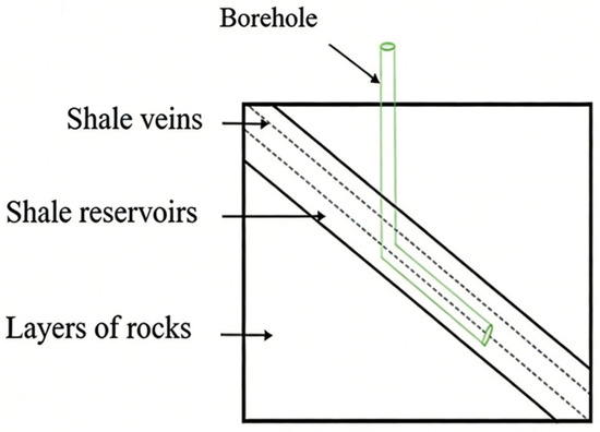
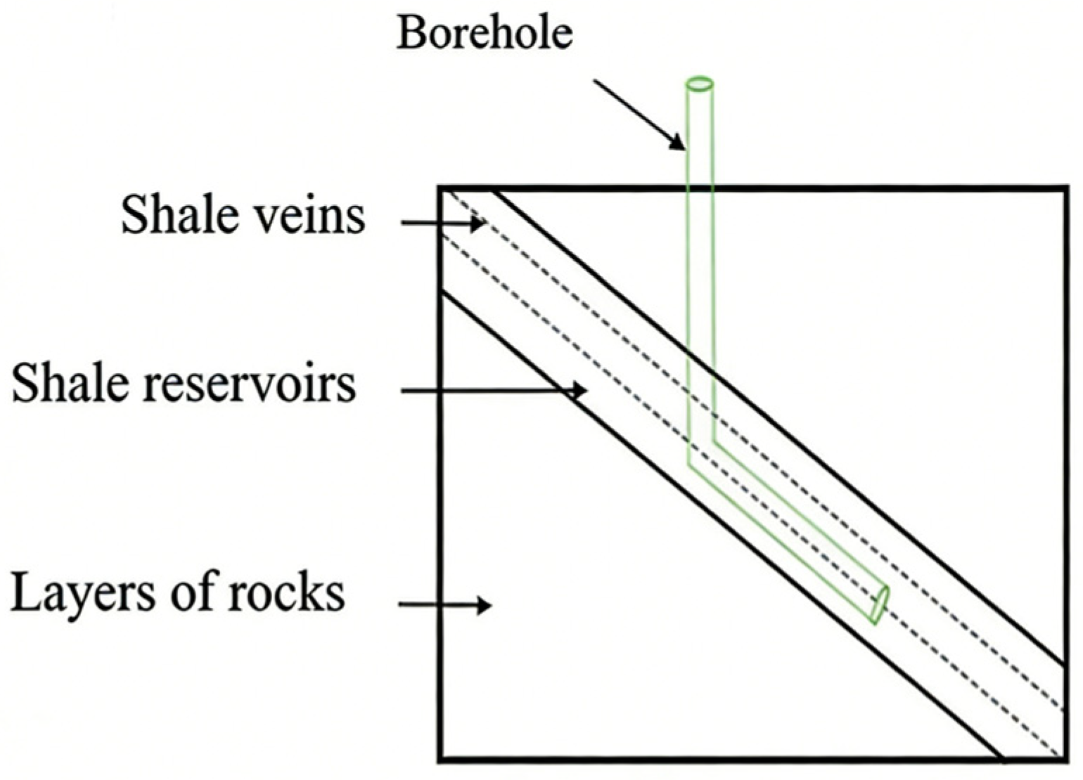
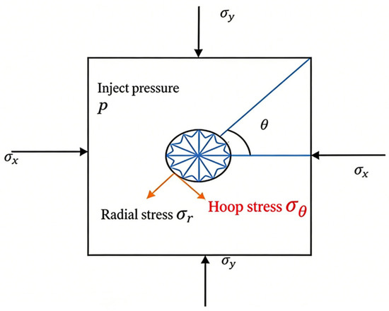
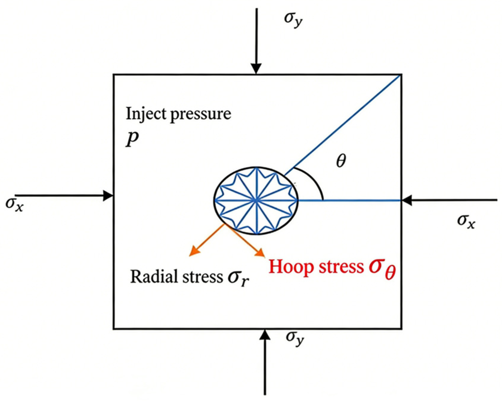
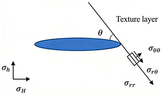
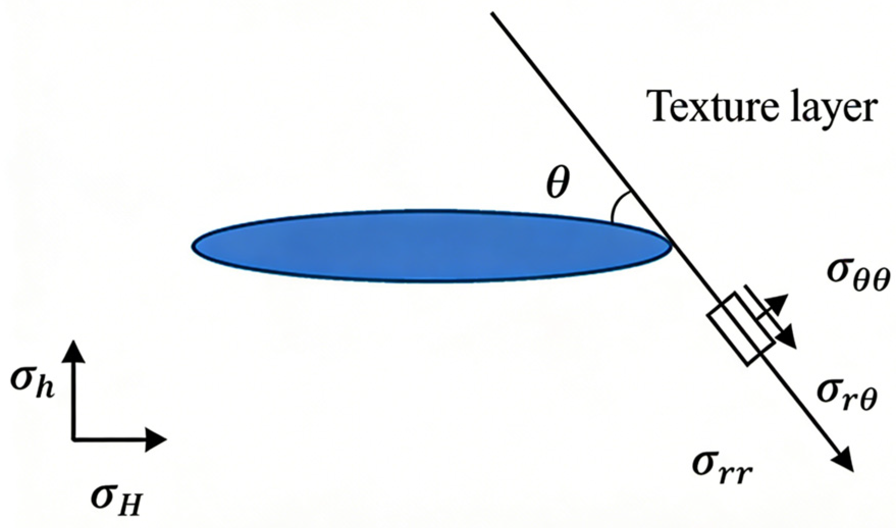
The positional relationship of shale in actual conditions is shown in Figure 1, and the force acting on the rocks around the wellbore is shown in Figure 2.
Figure 1.
Relationship between the borehole and shale reservoir.
Figure 2.
Force diagram of rocks around wellbore.
Taking compressive stress as positive and tensile stress as negative, the formulas for the three principal stresses on the wellbores of horizontal wells are as follows:
where is the maximum principal stress around the wellbore, MPa; is the intermediate principal stress around the wellbore, MPa; is the minimum principal stress around the wellbore, MPa; is the radial normal stress of the wellbore, MPa; is the axial normal stress of the wellbore, MPa; is the maximum horizontal in situ stress of the wellbore, MPa; is the minimum horizontal in situ stress, MPa; is the shear stress, MPa; R is the wellbore radius, m; P is the injection pressure inside the wellbore, MPa; and is the pore pressure, MPa.
When the failure mode of the wellbore is tensile failure, the maximum tensile stress is:
2.2. Fracture Propagation Model for Laminated Shale
For tensile failure of the fracture to occur, the stress intensity factor at the crack tip must satisfy:
Assuming that the critical water pressure required for the linear fracture to propagate in the matrix is , then:
where is the elastic modulus of the target shale matrix, GPa; is the half-length of the fracture, m; and is the surface energy per unit area of the target shale matrix, MPa·m.
The stress state when the fracture extends to the lamina is shown in Figure 3.
Figure 3.
Fracture extending to the lamina.
Under the action of far-field stress, the normal stress and shear stress at the laminae can be expressed as:
According to the two-dimensional elasticity theory, the normal stress and shear stress on the laminae under the actions of internal water pressure and far-field stress can be expressed as:
During the calculation process, when the lamina plane is in an open state, ; when , shear failure occurs, and the pressure during fracture propagation can be obtained. If we let , then:
Based on the analysis of Figure 3, when hydraulic fractures propagate to the laminae, the direction of fracture propagation is affected by laminar interface strength and in situ stress driving effect. Based on the relationship between and , fracture direction after encountering laminae is determined.
3. Establishment and Validation of Hydraulic Fracture Numerical Model for Laminated Shale
The mesoscopic parameters of the shale numerical model specimens are detailed in Table 1.
Table 1.
Mesoscopic parameters of shale numerical model specimens.
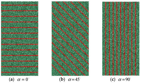
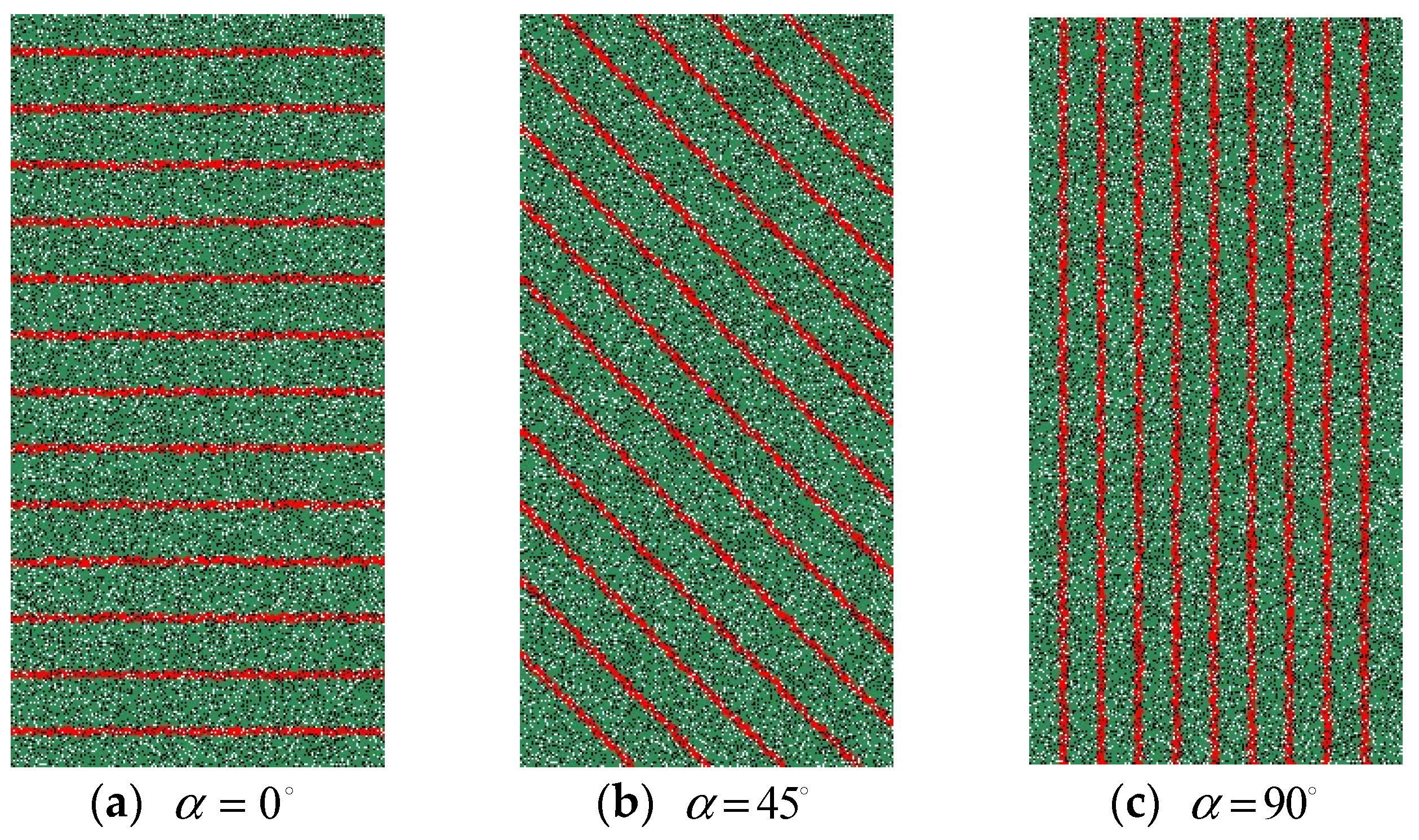
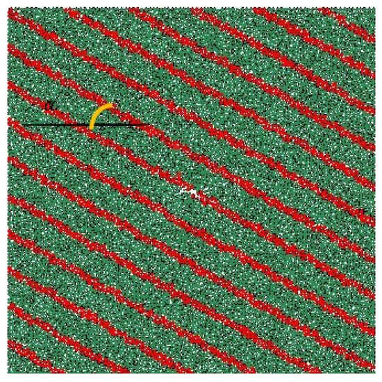
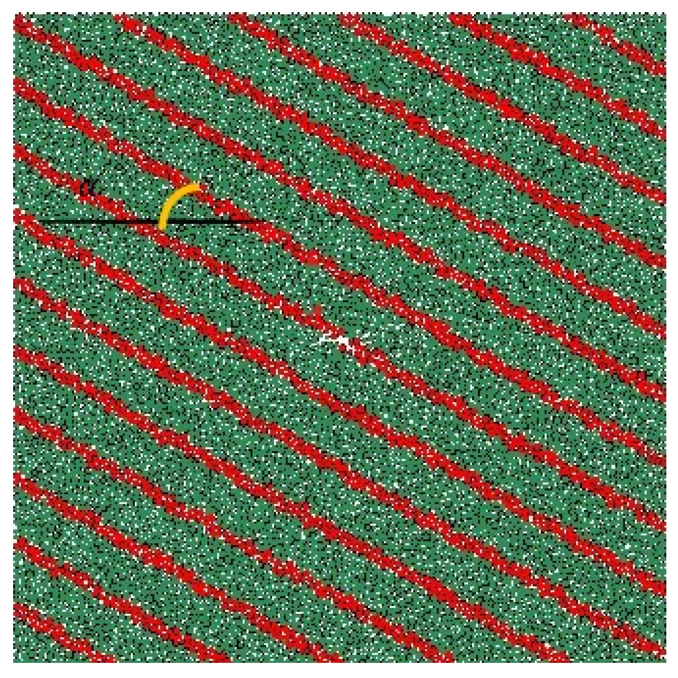
The software PFC2D 6.0 was used to set the model diameter to 50 mm and length to 100 mm. The shale particle size ranges from 0.08 mm to 0.13 mm, with a density of 2650 kg/m3, and the contact model was set as a linear contact model. Furthermore, the contact between particles was converted to parallel-bonded contact using the “contact model” command, and a two-dimensional numerical model of shale specimens was established with 20,353 particles. In the simulation, the wall displacement rate was 0.05 m/s, and the triaxial loading of the shale model specimens needed to be realized through the FISH function, with a confining pressure and a velocity. In the figure, green represents the matrix and red represents the laminae. According to the parameters in Table 1, numerical models with lamina angles of , , and were established, as shown in Figure 4.
Figure 4.
Numerical models of shale with different lamina dip angles.
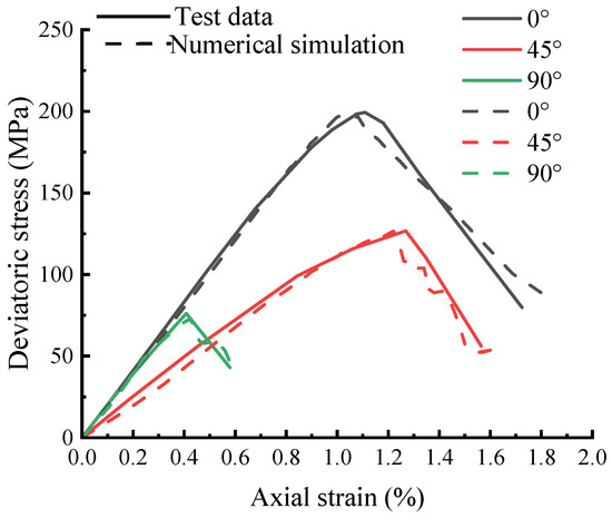
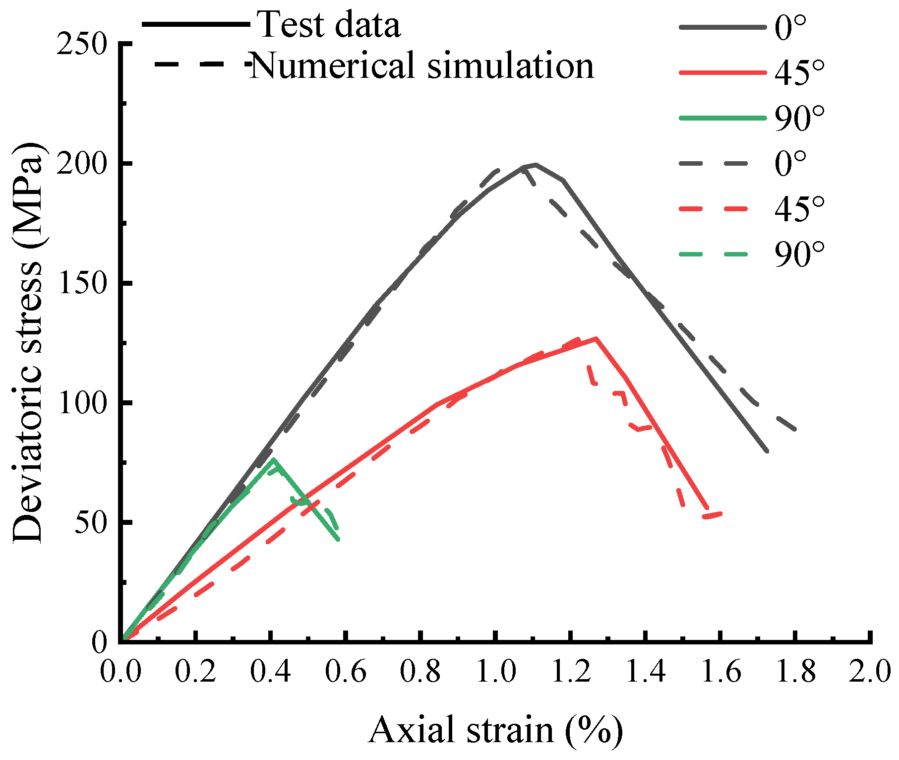
Further, numerical simulations were conducted on the numerical models under a constant confining pressure of 50 MPa, and the stress–strain curves of the specimens were obtained and compared with the experimental results, as shown in Figure 5.
Figure 5.
Comparison of numerical simulation and experimental curves for lamina dips of 0°, 45°, and 90°.
From the comparison results in Figure 5, it can be seen that in both numerical simulations and experiments, the maximum deviatoric stress values for lamina angles of 90° are very low, while the curves for 0° show significant increases, with relatively larger maximum values. The numerical simulations and experiments exhibit the same pattern, indicating that the numerical simulations are consistent with the observed laws.
A hydraulic fracture propagation model of laminated shale was established as shown in Figure 6. The model size and lamina parameters are referenced to the lamina shale parameters of the Minfeng Central Block in the Jiyang Depression. The side length of the numerical sample model was set to 100 mm, and the angles α between each lamina and the horizontal direction were set to 0°, 15°, 45°, 60°, 75°, and 90°.
Figure 6.
Hydraulic fracture propagation model of laminated shale.
To better study and simulate the propagation law of shale hydraulic fractures, certain assumptions need to be made for the model, as follows:
- (1)
- Shale bedding is uniformly distributed and continuous. Possible bedding absence, local discontinuities, or randomly interspersed microfractures in actual formations are ignored. The mechanical anisotropy of bedding is only simulated through preset particle/block contact parameters.
- (2)
- Shale lithology is homogeneous. The local influence of microscale heterogeneity in mineral composition (present in actual formations) on fracture propagation is ignored.
- (3)
- Shale is a linear elastic material. Viscoelastic/viscoplastic deformation of shale under high stress or hydraulic action is ignored. Deformation characteristics are only described using the elastic modulus and Poisson’s ratio of particles/blocks.
- (4)
- Mechanical parameters of shale are constant and isotropic. The dynamic variation in parameters with depth and stress state in actual formations is ignored.
- (5)
- Shale failure follows a preset mesoscopic fracture criterion, and the criterion parameters match the results of macroscopic mechanical tests. Complex fracture mechanisms between mineral particles at the mesoscopic scale are ignored.
- (6)
- Fracturing fluid is an incompressible fluid. The influence of its volume change under high pressure on pumping pressure and fracture propagation rate is ignored.
- (7)
- Fracturing fluid flow in fractures obeys Darcy’s Law. Inertial forces and non-Darcy effects under high-velocity flow are ignored, and fluid seepage/filtration in the shale matrix is not considered.
- (8)
- Shale is discretized into a collection of regular particles, with particle size and shape set as preset values. The irregular mesoscopic structure of actual rock is ignored.
- (9)
- Contact interaction between particles is only transmitted through a preset constitutive model. Microscopic forces between particles (such as van der Waals forces and electric forces) are ignored.
- (10)
- Fracturing fluid temperature change and shale thermal expansion/contraction on fracture propagation is ignored.
4. Laws of Hydraulic Fracture Propagation and Analysis of Sensitive Factors in Laminated Shale
4.1. Influence Law Analysis of In Situ Stress
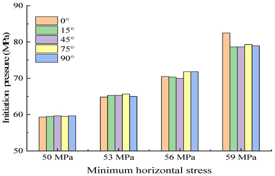
Four groups of minimum horizontal principal stresses were set as 50 MPa, 53 MPa, 56 MPa, and 59 MPa respectively, with the maximum horizontal principal stress fixed at 62 MPa. For each group, lamina dips of 0°, 15°, 45°, 75°, and 90° were configured to investigate the relationship between initiation pressure and in situ stress, as shown in Figure 7.
Figure 7.
Variation in initiation pressure with lamina angle under different in situ stresses.
When comparing each group in Figure 7, the initiation pressures under different lamina angles are quite similar, with the difference not exceeding 6%, indicating that the initiation pressure is less affected by the lamina angle. When comparing the four groups collectively, it is observed that the initiation pressure increases with the increase in confining pressure, with the difference exceeding 25%. The in situ stress has a more important effect on initiation pressure than the lamina angle.
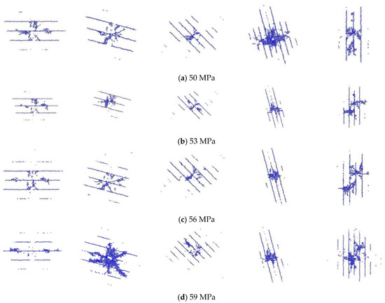
The fracture propagation patterns under different in situ stresses are shown in Figure 8. It can be seen that, as the horizontal principal stress difference decreases, hydraulic fractures gradually deflect toward the minimum horizontal principal stress. At a 12 MPa difference (minimum stress 50 MPa), fractures tend to propagate along the maximum principal stress. While at a 6 MPa difference (minimum stress 56 MPa), this directionality weakens, with more prominent extension toward the minimum stress. For small lamina dip angles (0°, 15°), fractures are significantly influenced by lamellar interfaces upon encounter, tending to propagate along laminae regardless of stress difference changes. For large dip angles (45°, 75°, 90°), fractures are more strongly driven by in situ stress, readily penetrating laminae to extend toward the maximum principal stress, with higher penetration proportions at larger stress differences. When the stress difference is 3 MPa (minimum stress 59 MPa), the average length of the main fracture is approximately 41.2 ± 2.8 mm, the number of secondary fractures is 17 ± 2, the fracture network complexity index is 0.85 ± 0.04, and the lamina penetration rate at a 75° dip angle is 65% ± 3%. When the stress difference increases to 12 MPa (minimum stress 50 MPa), the average length of the main fracture increases to 57.6 ± 3.5 mm (relative increase of 39.8%), the number of secondary fractures decreases to 6 ± 1 (relative decrease of 64.7%), the fracture network complexity index drops to 0.31 ± 0.03 (relative decrease of 63.5%), and the lamina penetration rate rises to 92% ± 2% (relative increase of 41.5%). A small stress difference (3 MPa, minimum stress 59 MPa) results in more complex fracture morphology, especially at 75° dip, with more branches and dispersed directions. A large stress difference (12 MPa, minimum stress 50 MPa) reduces network complexity, concentrating main fractures along the maximum principal stress, though fractures at 15° dip remain relatively complex.
Figure 8.
Diagram of hydraulic fracture propagation under different in situ stresses.
4.2. Influence Law Analysis of Injection Rate
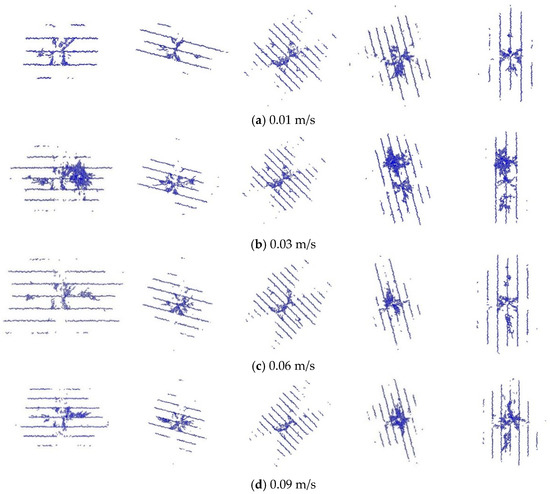
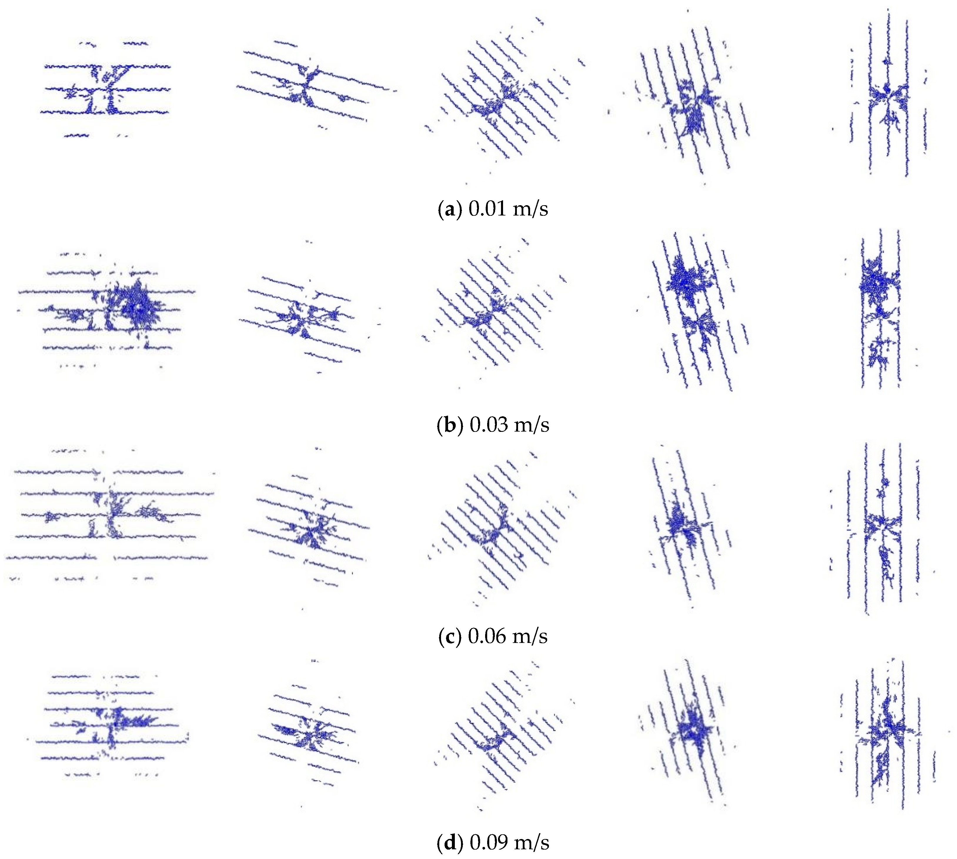
The minimum principal stress was set to 56 MPa, and the maximum horizontal principal stress was set to 62 MPa. The viscosity of the fracturing fluid was 5 mPa·s, and the injection rates were set to 0.01 m/s, 0.03 m/s, 0.06 m/s, and 0.09 m/s, respectively. The simulation results of fracture propagation are shown in Figure 9. As shown in Figure 9, fractures form a fracture network around the injection hole, and the fractures are significantly affected by the laminae. At lamina angles of 0° and 15°, fractures propagate along the lamina planes in the same direction as the laminae when encountering them. At lamina angles of 45°, 60°, 75°, and 90°, fractures mainly extend along the direction of the laminae, but some fractures also propagate through the laminae. As the injection rate increases from 0.01 m/s to 0.09 m/s, the complexity of the fracture network shows a trend of first increasing and then decreasing, with the most complex fracture morphology observed at an injection rate of 0.03 m/s.
Figure 9.
Diagram of hydraulic fracture propagation under different injection rates.
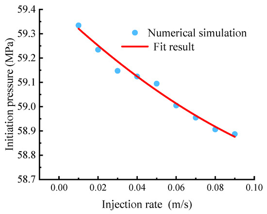
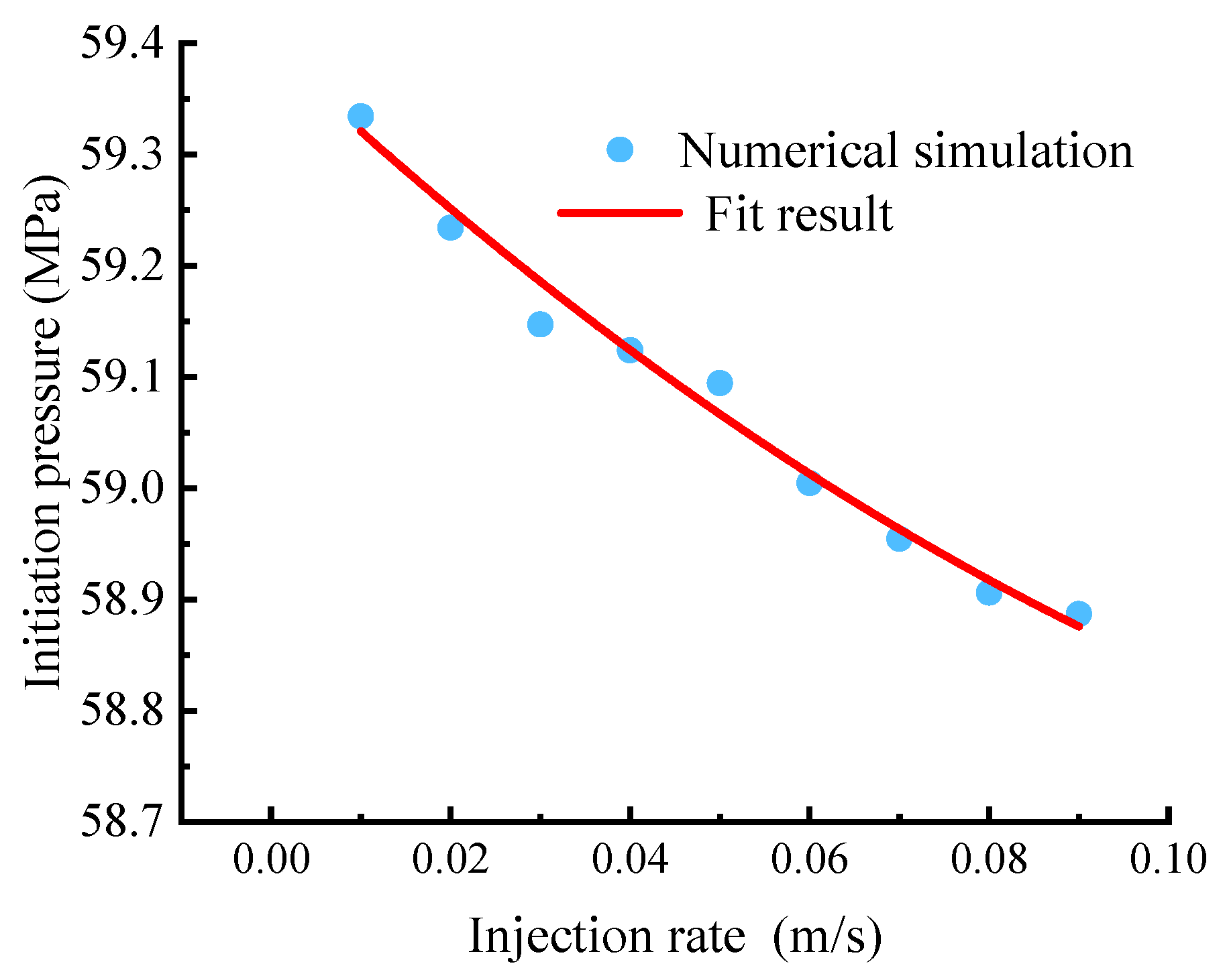
The same injection time was maintained, while the fluid loading rate was varied. The injected fluid rate was applied in a graded manner, and the initiation pressure of each set was recorded as shown in Figure 10. It can be seen from Figure 10 that, as the injection rate of the fracturing fluid increases, the shale initiation pressure shows a decreasing trend. When the injection rate of the fracturing fluid increases from 0.01 m/s to 0.09 m/s, the initiation pressure decreases from 59.34 MPa to 58.88 MPa. The decreasing amplitude becomes smaller in the later stage, especially when the injection rate exceeds 0.05 m/s.
Figure 10.
Influence of injection rate on initiation pressure in laminated shale.
4.3. Influence Law Analysis of Injection Pressure
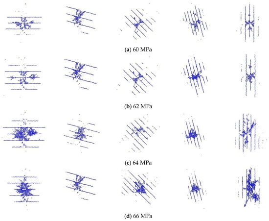
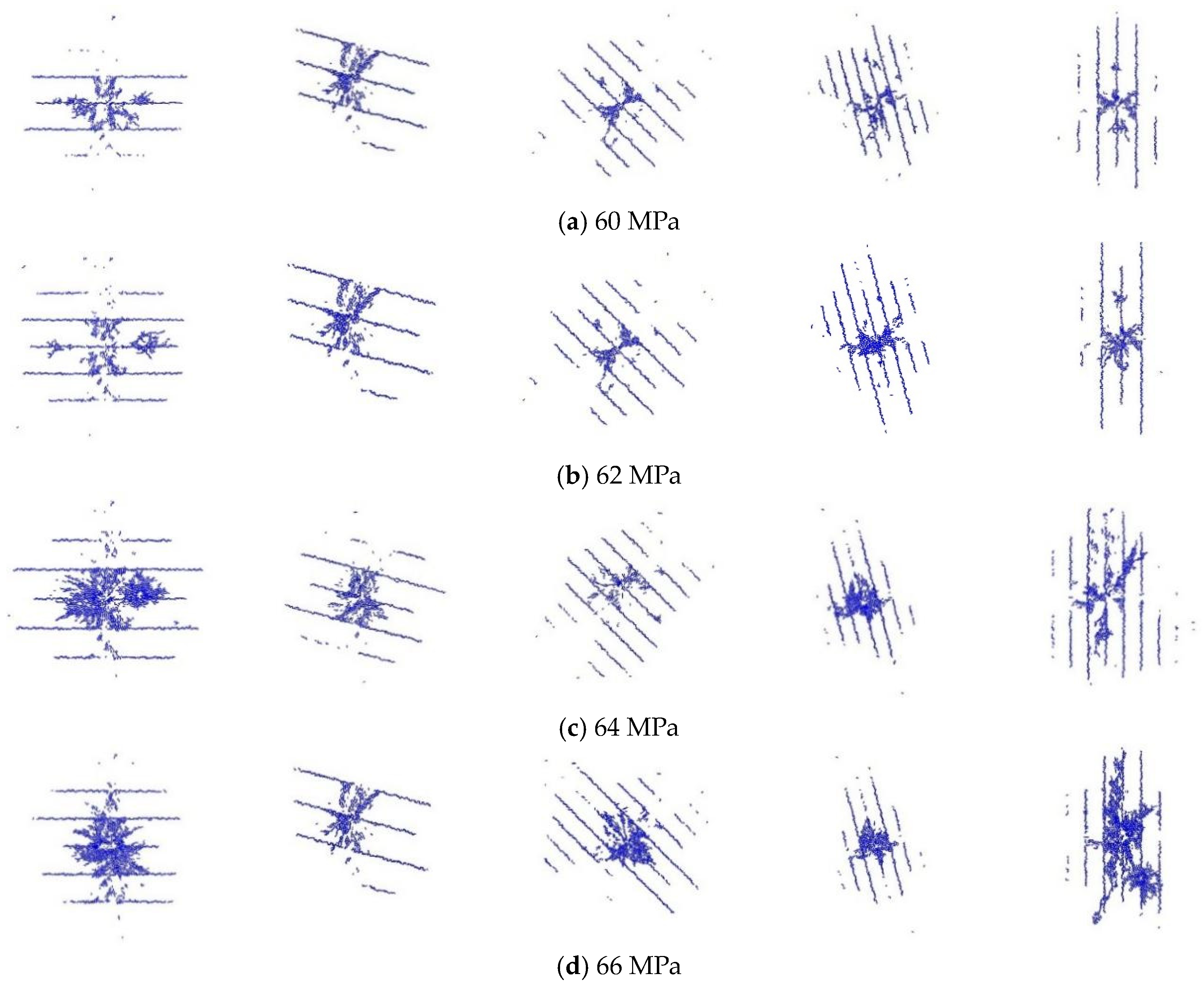
The minimum principal stress was set to 56 MPa, and the maximum horizontal principal stress was set to 62 MPa. The fracturing fluid viscosity was 5 mPa·s, and the injection pressures were set to 60 MPa, 62 MPa, 64 MPa, and 66 MPa, respectively. The fracture propagation is shown in Figure 11.
Figure 11.
Hydraulic fracture morphologies under different injection pressures.
As can be seen from Figure 11, under the condition of low injection pressure (e.g., 60 MPa), the length of the main fracture increases significantly, and the fracture shows a more obvious trend of propagating outward from the model. This indicates that a lower injection pressure is more conducive to the extension of the main fracture, while inhibiting the development of secondary fractures. Under the condition of high injection pressure (e.g., 66 MPa), fractures are mainly concentrated near the injection hole, forming a complex and dense network of short fractures with a significant increase in the number of branched fractures. This is because high injection pressure can provide a stronger driving force, prompting the fluid to induce more secondary fractures at lamellar interfaces or weak areas, thereby enhancing the complexity of the fracture network. Regardless of the injection pressure level, fracture propagation is significantly affected by the laminae: when the lamina dip angle is small (e.g., 0°, 15°), fractures tend to extend along the direction of the laminae after encountering them; when the lamina dip angle is large (e.g., 45°, 75°, 90°), some fractures will penetrate the laminae and continue to propagate, while others still extend along the direction of the laminae. This reflects the fracture deflection characteristics under the combined action of lamellar interfaces and in situ stress. Injection pressure regulates the balance between the extension of the main fracture and the development of secondary fractures by changing the fluid driving energy. Low pressure promotes the extension of the main fracture, and high pressure promotes the formation of a complex network of short fractures, with this process being consistently constrained by the lamellar structure.
4.4. Influence Law Analysis of Lamina Density
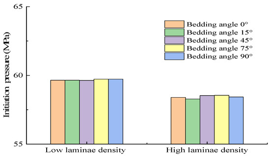
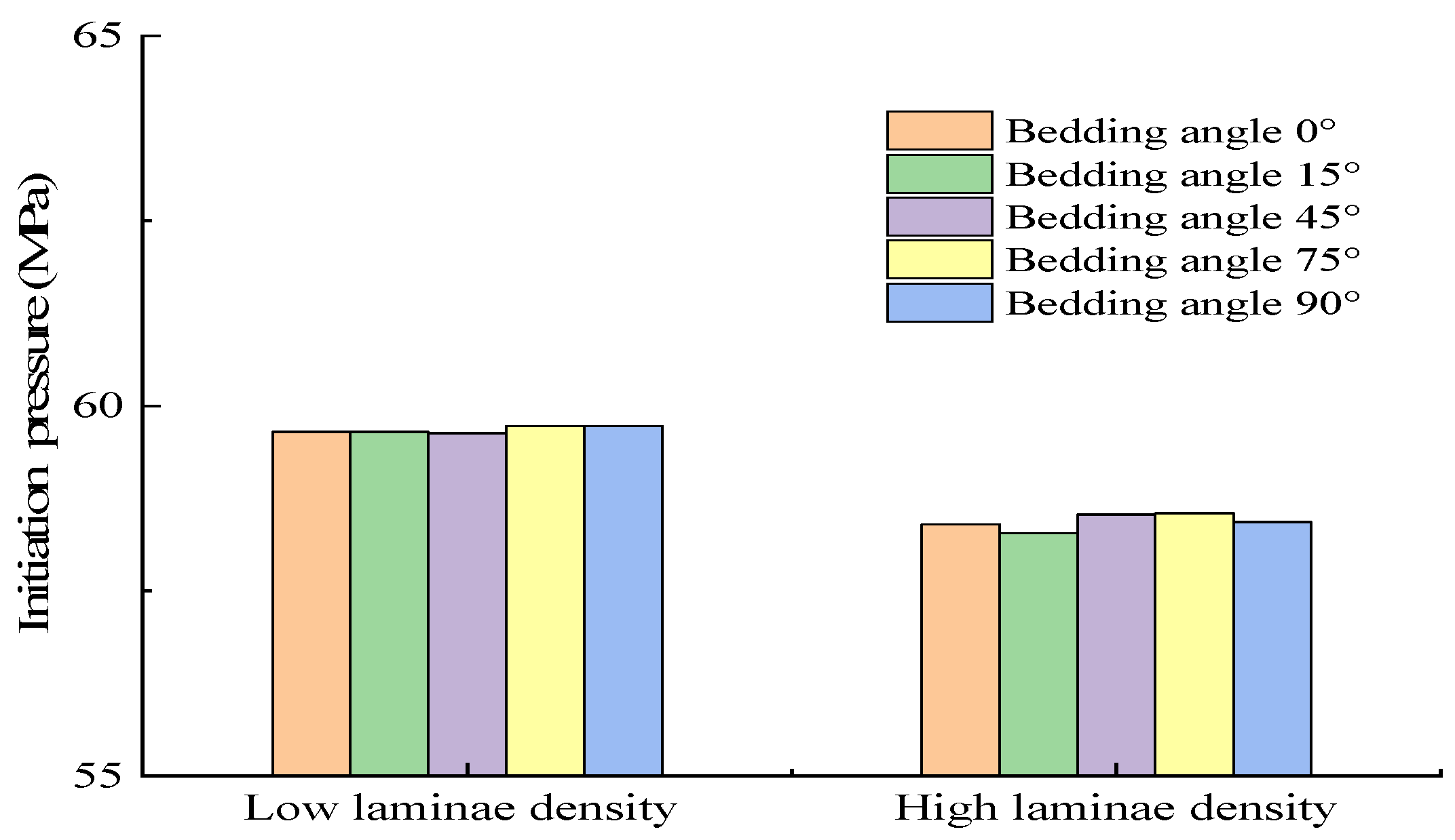
The lamina density in the Jiyang Depression is approximately 4–10 strips per 100 mm. Therefore, two scenarios were set for simulation: low lamina density (4, 5 strips/100 mm) and high lamina density (9, 10 strips/100 mm). To analyze the influences of laminae on shale fracture propagation, the lamina densities were set to 4 strips/100 mm, 5 strips/100 mm, 9 strips/100 mm, and 10 strips/100 mm, respectively. A comparison of the initiation pressures at different lamina angles between high lamina density and low lamina density is shown in Figure 12.
Figure 12.
Variation in initiation pressure with lamina angle under different lamina densities.
As shown in Figure 12, the initiation pressure at low lamina density is higher than that at high lamina density. The initiation pressure at low lamina density (4 strips/100 mm) is about 59.7 MPa, while it is 58.5 MPa at high lamina density (10 strips/100 mm). Lamina density can reduce the shale strength, alter mechanical properties, and, consequently, lower the fracture initiation pressure. When the lamina density remains constant, increasing or decreasing the lamina angle has little effect on the initiation pressure, and the initiation pressure remains almost unchanged. In the simulation of high-density laminae, the difference in initiation pressure between lamina angles of 15° and 45° is relatively large.
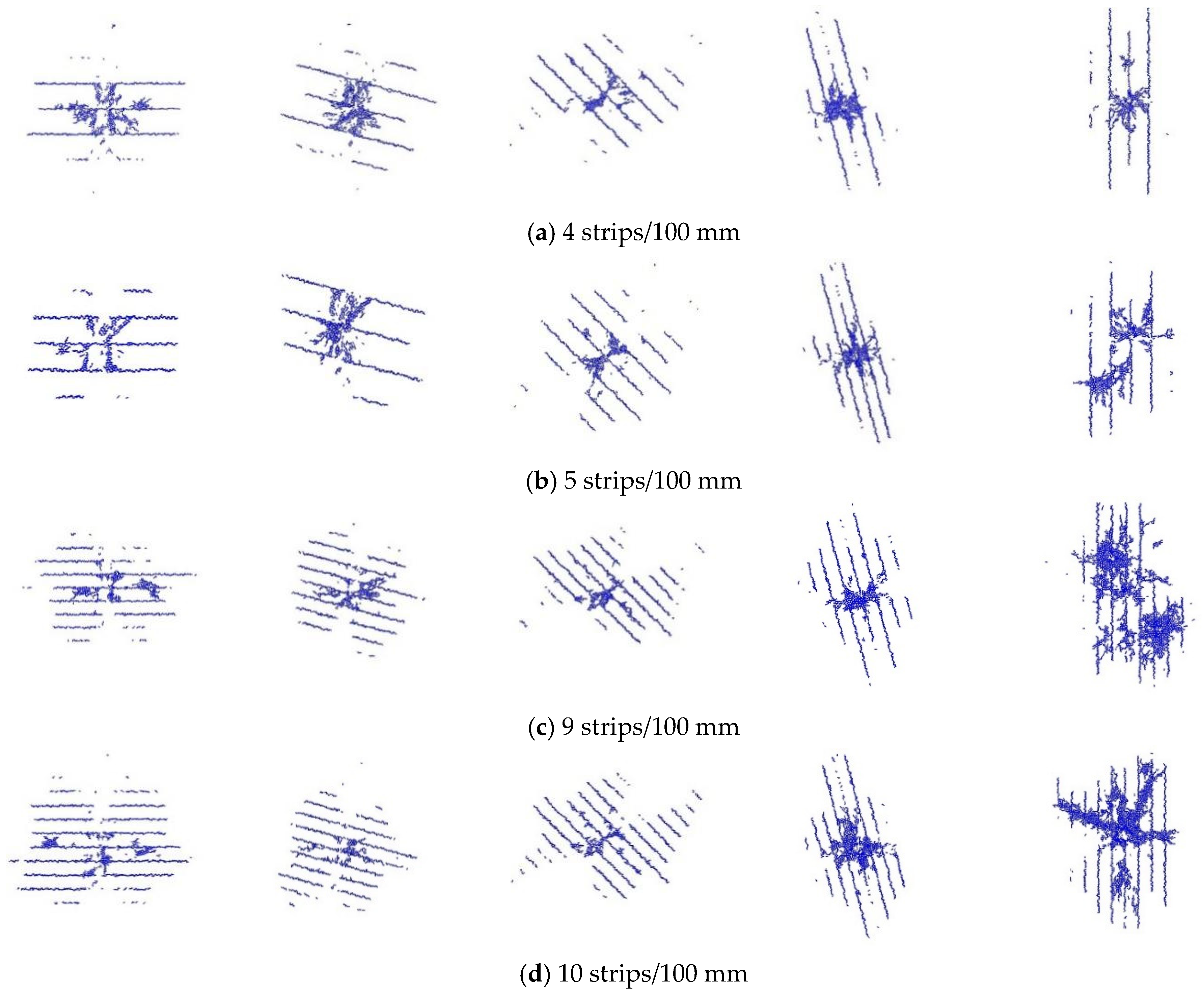
Shale laminae were set as 4 strips/100 mm, 5 strips/100 mm, 9 strips/100 mm, and 10 strips/100 mm, respectively, to study the fracture propagation patterns at different lamina angles, as shown in Figure 13.
Figure 13.
Diagrams of hydraulic fracture propagation under different lamina densities.
As can be seen from Figure 13, under high lamina density (e.g., 9 strips/100 mm, 10 strips/100 mm), fractures are more likely to penetrate the lamina interfaces and extend toward the direction of the maximum horizontal principal stress. For example, when the lamina dip angles are 45°, 75°, and 90°, hydraulic fractures will penetrate the laminae and continue to propagate, being weakly constrained by the direction of the laminae. Under low lamina density (e.g., 4 strips/100 mm, 5 strips/100 mm), fractures propagate around the injection hole and tend to extend along the direction of the laminae, with a more significant guiding effect from the lamina interfaces. The influence of lamina density on fracture paths has a synergistic effect with lamina dip angles. When the lamina dip angles are small (0°, 15°), fractures are easily affected by the direction of the laminae regardless of the density, but some fractures still penetrate the laminae under high lamina density. When the lamina dip angles are large (45°, 75°, 90°), high lamina density significantly promotes fractures to penetrate the laminae, while, under low lamina density, the tendency of fractures to extend along the laminae is more obvious. Under low lamina density, the directional propagation of fractures along the laminae is more prominent, and the fracture network has strong directionality. Meanwhile, under high lamina density, the fracture proportion penetrating the laminae increases, and, combined with the driving force of in situ stress, the fracture network tends to concentrate more toward the direction of the maximum principal stress, with complexity regulated by the combined action of lamina interfaces and in situ stress. Lamina density regulates the balance between “propagation along laminae” and “propagation through laminae” by changing the distribution density of lamina interfaces. High lamina density enhances the penetrability of fractures, while low lamina density enhances the guidance of fractures along the laminae, and this process is synergistically constrained by lamina dip angles and in situ stress.
5. Discussion
This study clarifies the influence laws of in situ stress, injection parameters, and lamina characteristics on fracture propagation. These findings provide a key theoretical basis for the design of hydraulic fracturing engineering in shale oil reservoirs. In practical operations, injection parameters can be optimized based on the in situ stress state and lamina development characteristics of the formation to effectively control the direction and morphology of fracture propagation, construct a more ideal fracture network, and improve the recovery efficiency of shale oil reservoirs [48]. This research has achieved certain results in discrete element simulation, but still has limitations. In the future, consideration can be given to building a three-dimensional model, incorporating more practical factors (such as rock heterogeneity, natural fractures, etc.), and conducting quantitative research on multi-factor coupling to further deepen the understanding of fracture propagation laws in lamina-developed shale, thereby providing more accurate theoretical support for the efficient development of shale oil reservoirs [49,50].
Lamina is a core structural feature of shale in continental faulted basins of eastern China (represented by the Jiyang Depression), with a density ranging from 4 to 10 strips/100 mm. This lamellar structure exerts a crucial regulatory effect on the initiation, propagation, and network formation of hydraulic fractures, key factors determining the stimulation effect of shale oil reservoirs. Currently, numerous studies have employed the discrete element method (DEM, including PFC 2D 6.0) to investigate hydraulic fracture propagation in shale, focusing primarily on the influences of in situ stress difference, injection rate, and natural fractures. However, few studies have systematically explored the synergistic effects of lamina characteristics (dip angle) with construction parameters (injection rate, pressure) and geological conditions (in situ stress) on fracture behavior. This research gap restricts the accurate prediction of fracture morphology and the optimization of fracturing designs for lamina-developed continental shale.
To address this limitation, this study first established a PFC2D 6.0 numerical model of lamina-developed shale, validated rationality by comparing simulation results with experimental stress–strain curves, and then conducted controlled-variable simulations to clarify the coupling mechanisms of multiple factors on fracture propagation. Unlike previous DEM studies that analyzed single factors in isolation (e.g., only in situ stress or lamina angle), this research quantifies the interactive effects of lamina features with other variables. For instance, under high lamina density (9–10 strips/100 mm), fractures penetrate lamellar interfaces more easily and extend along the maximum horizontal principal stress, even at large dip angles (45°, 75°, 90°). In contrast, low lamina density (4–5 strips/100 mm) strengthens lamina guidance, causing fractures to propagate along laminae near the injection hole, regardless of stress difference changes. Additionally, this study reveals a non-monotonic relationship between injection rate and fracture complexity—fracture networks are most complex at an injection rate of 0.03 m/s, rather than increasing linearly with rate-correcting, the oversimplified understanding in prior studies that “higher injection rates always enhance fracture complexity”. These findings fill the gap in multi-factor coupling research on lamina-developed shale using DEM and provide more targeted insights for fracturing engineering.
The analysis also identifies the distinct regulatory roles of two typical lamina density scenarios (low: 4–5 strips/100 mm; high: 9–10 strips/100 mm) in fracture paths. Low density enhances the “lamina guidance effect”: clay-rich lamellar interfaces act as weak planes, causing fractures to deflect along laminae and form directional networks. High density strengthens the “stress-driven penetration effect”: dense lamellar interfaces increase the probability of fracture–lamina interactions, and, under the driving force of in situ stress, fractures penetrate more laminae and concentrate toward the maximum principal stress direction. This differentiation complements the single “weak plane theory” in previous lamina shale studies and provides a more comprehensive mechanistic explanation for fracture propagation patterns.
Owing to time and model constraints, this research still has aspects requiring further refinement. First, the current PFC2D model simplifies shale as a two-dimensional system, which cannot fully reflect the three-dimensional spatial distribution of laminae and the vertical propagation behavior of fracture factors that significantly affect the actual fracturing effect of horizontal wells. Future work will construct a 3D discrete element model to simulate the vertical extension range of fractures and their interactions with multi-layer laminae. Second, this study focuses on qualitative and semi-quantitative analysis of fracture propagation laws, but lacks a quantitative constitutive model that integrates lamina density, dip angle, and in situ stress to predict fracture initiation pressure and network complexity. Establishing such a model will be critical for translating research results into practical fracturing design parameters. Finally, the model does not consider natural fractures, which are widely present in Jiyang Depression shale. Incorporating natural fractures into the numerical model and exploring their coupling effect with laminae will further improve the accuracy of fracture propagation prediction.
Due to the limitations of the research scope and model settings, some work still needs to be further advanced. This study has clarified the variation laws and influencing factors of hydraulic fracture propagation in lamina-developed shale (especially the coupling effect of lamina density and lamina dip angle), and provided theoretical explanations for these variation laws. However, it lacks verification from macro-physical experiments, and further exploration is still required to investigate the consistency between the numerical simulation results and the actual fracture propagation characteristics of reservoirs. In the future, laboratory hydraulic fracturing physical experiments on lamina-developed shale cores will be conducted, combined with CT scanning and acoustic emission monitoring technologies, to verify the reliability of the numerical simulation model. Although this study has carried out qualitative and quantitative analyses on the fracture propagation laws under the action of single factors and multi-factor coupling, it has not yet established a fracture propagation prediction model that considers lamina characteristics. The next research direction will be to construct a hydraulic fracture propagation model for lamina-developed shale that integrates lamina density, lamina dip angle, in situ stress, and injection parameters. This is crucial for improving the accuracy of hydraulic fracturing design in shale oil reservoirs of the Jiyang Depression.
6. Conclusions
This paper mainly conducts analysis to study the mechanical properties and fracture propagation laws of shale under load by using the discrete element method. The main conclusions are as follows:
- (1)
- Initiation pressure rises significantly with increasing minimum horizontal principal stress. The horizontal principal stress difference dominates fracture direction, with larger differences enhancing deflection toward the maximum principal stress. Small lamina dips (0°, 15°) guide fractures along laminae despite stress changes; larger dips (45°, 75°, 90°) see stress differences drive penetration, with higher differences increasing penetration proportion.
- (2)
- The injection rate is negatively correlated with the initiation pressure. When the injection rate increases from 0.01 m/s to 0.09 m/s, the initiation pressure decreases from 59.34 MPa to 58.88 MPa, though the decreasing amplitude slows down in the later stage. Injection pressure has a significant impact on fracture morphology and propagation patterns: low injection pressure (e.g., 60 MPa) is conducive to the extension of the main fracture, while high injection pressure (e.g., 66 MPa) promotes the formation of a complex and dense network of short fractures near the injection hole.
- (3)
- Lamina density and dip angle synergistically control fracture paths. High density (9–10 strips/100 mm) enhances lamina penetration, favoring extension toward maximum horizontal principal stress; low density (4–5 strips/100 mm) strengthens lamina guidance, with fractures propagating along laminae near the injection hole. Small dips reinforce lamina guidance; larger dips see high density promote penetration and low density enhance along-lamina extension.
Author Contributions
Conceptualization, M.L.; Funding acquisition & Data curation: X.Z.; Formal analysis, D.W.; Methodology, F.Y.; Investigation, K.W.; Writing—original draft: Z.Z. All authors have read and agreed to the published version of the manuscript.
Funding
This work was financially supported by the National Oil & Gas Major Project (2024ZD1405100), the Natural Science Foundation of Shandong Province (ZR2024QE090), the National Natural Science Foundation of China (U24B6002), the Dongying Science Development Fund (DJ2023001), the National Natural Science Foundation Project of China (52204022), the Natural Science Foundation of Shandong Province (ZR2022ME068, ZR2022ME152), the Youth Innovation and Technology Support Program for Shandong Provincial Universities (2022KJ066), the Major Special Project for Scientific and Technological Innovation of Dongying City (2023ZDJH110), the Horizontal Research Projects of Engineering Technology Research Institute, and the Sinopec Shengli Oilfield (3020019-22-FW2099-0102).
Data Availability Statement
The original contributions presented in this study are included in the article. Further inquiries can be directed to the corresponding author.
Conflicts of Interest
All authors were employed by the company Shengli Oilfield Branch Company, Sinopec. The authors declare that the research was conducted in the absence of any commercial or financial relationships that could be construed as a potential conflict of interest.
References
- Yang, Y.; Zhang, S.M.; Lv, Q.; Sun, Z.G.; Jiang, L.; Sun, H.X.; Liu, Z.P.; Lv, J.; Xing, X.D.; Ni, L.T. Theoretical understanding and technical practice of shale oil development in continental faulted basins in eastern China: A case study of Jiyang shale oil. Pet. Geol. Recovery Effic. 2024, 31, 1–15. [Google Scholar] [CrossRef]
- Yang, Y.M.; Li, X.; Yang, X.Y.; Li, X.W. Influence of reservoirs/interlayers thickness on hydraulic fracture propagation laws in low-permeability layered rocks. J. Pet. Sci. Eng. 2022, 219, 1–15. [Google Scholar] [CrossRef] [Scilit]
- Zhao, Z.; Li, X.; He, J.; Mao, T.; Li, G.; Zheng, B. Investigation of fracture propagation characteristics caused by hydraulic fracturing in naturally fractured continental shale. J. Nat. Gas Sci. Eng. 2018, 53, 276–283. [Google Scholar] [CrossRef] [Scilit]
- Wang, X.; Li, D.Q.; Jiang, W.; Liu, Y.; Zhang, X.M. Influence of overburden pressure hydration on hydraulic fracture propagation in shale. Nat. Gas Ind. 2019, 39, 81–86. [Google Scholar] [CrossRef]
- Sun, Y.W.; Cheng, Y.F.; Hao, Y.C. Analysis of borehole stability for inclined wells in fractured carbonate formation. Fresenius Environ. Bull. 2019, 28, 3893–3899. [Google Scholar]
- Sun, Y.W.; Meng, M.; Dai, X.; Liu, G.; Li, Y.; Zhang, C.; Yang, S.; Wang, H. Large-scale experiments of the borehole instability on shale formation influenced by drill pipe rotation. Energy Sci. Eng. 2019, 7, 2895–2920. [Google Scholar] [CrossRef] [Scilit]
- Li, Q.; Li, Q.C.; Wang, F.L. Settling behavior and mechanism analysis of kaolinite as a fracture proppant of hydrocarbon reservoirs in CO2 fracturing fluid. Colloids Surf. A Physicochem. Eng. Asp. 2025, 724, 137463. [Google Scholar] [CrossRef] [Scilit]
- Sun, Y.; Cheng, Y.; Li, C. Mechanical properties research of unconsolidated hydrate-bearing sediments under the effect of clay minerals. PLoS ONE 2025, 20, e0319772. [Google Scholar] [CrossRef] [Scilit]
- Sun, Y.W.; Sun, D.X.; Zhao, Y.Z.; Gao, Y.P.; Li, C.; Dai, X.D.; Wang, Y.L.; Cheng, Y.F. Development and Performance Evaluation of an Intelligent Sand Control Screen Based on Polyphenylene Sulfide. ACS Omega 2022, 7, 18063–18072. [Google Scholar] [CrossRef] [Scilit]
- Hubbert, M.K.; Willis, D.G. Mechanics of Hydraulic Fracturing. Trans. AIME 1957, 210, 153–168. [Google Scholar] [CrossRef] [Scilit]
- Feng, G.R.; Fan, Y.J.; Wang, P.F. Study on propagation law of hydraulic fractures in rock-like materials based on discrete element method. J. China Coal Soc. 2019, 13, 1–15. [Google Scholar]
- Lv, Q.; Lv, J.; Cheng, Z.Y.; Song, Y.; Hou, J. Study on 4D in-situ stress evolution law of shale oil reservoirs based on mechanical time-variability. Pet. Geol. Recovery Effic. 2024, 31, 56–65. [Google Scholar] [CrossRef]
- Wang, X.Q.; Zhong, Y.; Wan, Y.Y.; Wen, Y.Q.; Wu, S.; Zhang, M.Y.; Shen, Y.H.; Ge, H.K.; Xian, C.G.; Chen, H. Influence of laminae on mechanical properties of shale and its implications for hydraulic fracturing. J. China Univ. Pet. (Nat. Sci. Ed.) 2025, 49, 92–100. [Google Scholar] [CrossRef]
- Sun, Y.; Cheng, Y.; Zhao, J. Strength properties and strength criterion of unconsolidated hydrate-bearing sediment under the effect of clay minerals. Appl. Ocean Res. 2025, 163, 104738. [Google Scholar] [CrossRef] [Scilit]
- Wang, H.X. Principles of Hydraulic Fracturing; Petroleum Industry Press: Beijing, China, 1987. [Google Scholar]
- Zeng, N.D. Study on Hydraulic Properties and Fracture Propagation Mechanism of Reservoir Shale Based on Discrete Element Method; Chongqing University: Chongqing, China, 2021; pp. 1–104. [Google Scholar]
- Sun, Y.W.; Cheng, Y.F. Research on Strengthening Technology of Horizontal Well with Ridge Fractures in Shenhu Unconsolidated Hydrate Reservoir. In Proceedings of the 11th Academic Conference of Geology Resource Management and Sustainable Development; Elsevier/Engineering Village: Amsterdam, The Netherlands, 2023; pp. 7–15. [Google Scholar]
- Li, Q.C.; Wu, J.J.; Li, Q.; Wang, F.L.; Chen, Y.F. Sediment instability caused by gas production from hydrate-bearing sediment in northern South China Sea by horizontal wellbore: Sensitivity analysis. Nat. Resour. Res. 2025, 34, 1667–1699. [Google Scholar] [CrossRef] [Scilit]
- Lv, Y.; Song, C.; Jia, Y.; Zhang, L.; Wang, X.; Li, J.; Zhao, H. Analysis and Numerical Simulation of Hydrofracture Crack Propagation in Coal-Rock Bed. Comput. Model. Eng. Sci. 2015, 105, 69–86. [Google Scholar] [CrossRef]
- Liu, N.Z.; Zhang, Z.P.; Zou, Y.S. Propagation law of hydraulic fractures during multi-staged horizontal well fracturing in a tight reservoir. Pet. Explor. Dev. Online 2018, 45, 1129–1138. [Google Scholar] [CrossRef] [Scilit]
- Huang, J.; Griffiths, D.V.; Wong, S.W. Initiation pressure, location and orientation of hydraulic fracture. Int. J. Rock Mech. Min. Sci. 2012, 49, 59–67. [Google Scholar] [CrossRef] [Scilit]
- Tang, H.M.; Tang, Y.; Zheng, M.J.; Liu, J.; Bian, Y.Y. An Experimental Study on Lamina and Fracture Mode of Shale. J. Southwest Pet. Univ. (Nat. Sci. Ed.) 2022, 44, 51–61. [Google Scholar] [CrossRef]
- Zhao, W.Z.; Hu, S.Y.; Hou, L.H.; Yang, T.; Li, X.; Guo, B.C.; Yang, Z. Types and resource potential of continental shale oil in China and its boundary with tight oil. Pet. Explor. Dev. 2020, 47, 1–11. [Google Scholar] [CrossRef] [Scilit]
- Zhou, Z.Y. Fracture propagation mechanism and technical countermeasures of laminated shale oil reservoirs. Spec. Oil Gas Reserv. 2023, 30, 141–149. [Google Scholar]
- Yan, M.F.; Jin, Y.; Wei, S.M.; Xia, Y.; Chen, M. Study on evolution law of fracture toughness of ultra-deep laminated shale. Pet. Drill. Tech. 2025, 53, 159–167. [Google Scholar] [CrossRef]
- Niu, B.W. Macro and Meso Study on Fracture Morphology and Propagation Law of Shale Hydraulic Fracturing; Chongqing University: Chongqing, China, 2018; pp. 1–61. [Google Scholar]
- Xu, D.; Hu, R.L.; Gao, W.; Xia, J.G. Effects of laminated structure on hydraulic fracture propagation in shale. Pet. Explor. Dev. 2015, 42, 573–579. [Google Scholar] [CrossRef] [Scilit]
- Lv, W.Y.; He, C.C. Numerical simulation on the effect of pore pressure gradient on the rules of hydraulic fracture propagation. Energy Explor. Exploit. 2021, 39, 1878–1893. [Google Scholar] [CrossRef] [Scilit]
- Pan, L.H.; Zhang, S.C.; Zhang, J. Analysis of influencing factors on fracture morphology based on fluid-solid coupling. J. Xi’an Shiyou Univ. (Nat. Sci. Ed.) 2012, 27, 76–80+2. [Google Scholar]
- Wu, S.T.; Zhu, R.K.; Luo, Z.; Yang, Z.; Jiang, X.H.; Lin, M.J.; Su, L. Laminated structure and reservoir quality evaluation of typical continental shales in mid-western basins of China. China Pet. Explor. 2022, 27, 62–72. [Google Scholar]
- Wang, H.Y.; Xia, B.W.; Lv, Y.Y. Study on the Propagation Laws of Hydrofractures Meeting a Faulted Structure in the Coal Seam. Energies 2017, 10, 654. [Google Scholar] [CrossRef] [Scilit]
- Li, Z.C. Numerical Simulation Study on Propagation Characteristics of Hydraulic Fractures in Low-Permeability Reservoirs; Dalian University of Technology: Dalian, China, 2019; p. 11. [Google Scholar]
- Bai, Y.S.; Hu, Y.Q.; Li, J. Study on influence of fracturing fluid viscosity and injection rate on hydraulic fracture propagation behavior in laminated shale. Saf. Coal Mines 2023, 54, 18–24. [Google Scholar]
- Jing, D.Y.; Li, Z.P.; Zhao, X.H.; Chen, Z.W.; Guo, Y.G.; Zhang, H.T.; Hui, L. Numerical simulation of construction factors for vertical propagation of hydraulic fractures in tight thin interbeds. Sci. Technol. Eng. 2023, 23, 5988–5994. [Google Scholar] [CrossRef]
- Tang, H.Y.; Liang, H.P.; Zhang, L.H. Propagation patterns and influencing factors of hydraulic fractures in conglomerate reservoirs. Acta Pet. Sin. 2022, 43, 871–884. [Google Scholar]
- Ding, W.L.; Zeng, W.T.; Wang, R.Y.; Jiu, K.; Wang, Z.; Sun, Y.X.; Wang, X.H. Simulation of tectonic stress field and prediction of fracture distribution in shale reservoir. Earth Sci. Front. 2021, 44, 397–407. [Google Scholar] [CrossRef] [Scilit]
- Li, N.; Zhang, S.C.; Ma, X.F.; Zou, Y.S.; Chen, M.; Li, S.H.; Zhang, Y.N. Experimental study on the propagation mechanism of hydraulic fracture in glutenite formations. Chin. J. Rock Mech. Eng. 2017, 36, 2383–2392. [Google Scholar]
- Arora, S.; Mishra, B. Investigation of the failure mode of shale rocks in biaxial and triaxial compression tests. Int. J. Rock Mech. Min. Sci. 2015, 79, 109–123. [Google Scholar] [CrossRef] [Scilit]
- Yan, X.J. Numerical Simulation Study on Influence of Reservoir Brittleness on Hydraulic Fracture Complexity; Dalian University of Technology: Dalian, China, 2018; pp. 1–53. [Google Scholar]
- Fan, B.T.; Deng, J.G.; Liu, W.; Tan, Q.; Lin, H. Numerical simulation of the effect of formation plasticity on the propagation of hydraulic fractures. Sci. Technol. Eng. 2018, 18, 65–71. [Google Scholar]
- Zhang, J.W.; Liu, X.J.; Xiong, J.; Liang, L.X.; Zhang, W.; Zhang, X. Propagation law and main controlling factors of hydraulic fractures in conglomerate based on discrete element method. Pet. Geol. Oilfield Dev. Daqing 2023, 42, 48–57. [Google Scholar]
- Yu, H.Y.; Lebedev, M.; Zhou, J.Y.; Yang, C.; Liu, J.; Zhang, Y. The rock mechanical properties of lacustrine shales: Argillaceous shales versus silty laminae shales. Mar. Pet. Geol. 2022, 141, 105707. [Google Scholar] [CrossRef] [Scilit]
- Gunaydin, D.; Peirce, A.P.; Bunger, A.P.J. Laboratory Experiments Contrasting Growth of Uniformly and Nonuniformly-Spaced Hydraulic Fractures. J. Geophys. Res. Solid Earth 2020, 126, e2020JB020107. [Google Scholar] [CrossRef] [Scilit]
- Li, Y.W.; Zhu, C.F.; Zeng, Y.J.; Shui, H.C.; Fan, C.H.; Guo, W. Numerical simulations of the effects of bedding planes on hydraulic fracture propagation law in oil shale. Coal Geol. Explor. 2023, 51, 44–54. [Google Scholar] [CrossRef]
- Zhang, X.; Yin, M. Investigation of the Hydraulic Fracture Propagation Law of Layered Rock Strata Using the Discrete-Particle Model. Geofluids 2022, 2022, 8038085. [Google Scholar] [CrossRef] [Scilit]
- Ju, Y.W.; Bu, H.L.; Wang, G.C. Main characteristics of shale gas reservoirs and their influence on reservoir stimulation. Adv. Earth Sci. 2014, 29, 492–506. [Google Scholar] [CrossRef]
- Chen, M.; Jin, Y.; Zhang, G.Q. Rock Mechanics in Petroleum Engineering; Science Press: Beijing, China, 2008. [Google Scholar]
- Li, M.Y.; Liu, J.Y.; Xia, Y.F.; Chen, Y.; Zhang, H.; Wang, Y. Risk Prediction of Gas Hydrate Formation in the Wellbore and Subsea Gathering System of Deep-Water Turbidite Reservoirs: Case Analysis from the South China Sea. Reserv. Sci. 2025, 1, 52–72. [Google Scholar] [CrossRef] [Scilit]
- Cao, L.; Lv, M.; Li, C.; Wang, Y.; Zhang, H.; Liu, Z. Effects of Crosslinking Agents and Reservoir Conditions on the Propagation of Fractures in Coal Reservoirs During Hydraulic Fracturing. Reserv. Sci. 2025, 1, 36–51. [Google Scholar] [CrossRef] [Scilit]
- Li, Q.; Wang, Y.; Owusu, A.B. A modified Ester-branched thickener for rheology and wettability during CO2 fracturing for improved fracturing property. Environ. Sci. Pollut. Res. 2019, 26, 20787–20797. [Google Scholar] [CrossRef] [Scilit] [PubMed]

Disclaimer/Publisher’s Note: The statements, opinions and data contained in all publications are solely those of the individual author(s) and contributor(s) and not of MDPI and/or the editor(s). MDPI and/or the editor(s) disclaim responsibility for any injury to people or property resulting from any ideas, methods, instructions or products referred to in the content. |
© 2026 by the authors. Licensee MDPI, Basel, Switzerland. This article is an open access article distributed under the terms and conditions of the Creative Commons Attribution (CC BY) license.