


Abstract
In the extraction of shale gas and oil, the vibration characteristics of the drill string significantly influence wellbore quality, potentially leading to wellbore instability, excessive tool wear, and diminished drilling efficiency. This study tackles the challenges associated with drill string vibrations by developing an integrated technical framework of multi-field coupled dynamic modeling, Sobol-based key parameter identification, and NSGA-II-driven multi-objective structural optimization, and proposes a synergistic vibration suppression strategy combining structural parameter adjustment and hydraulic damper configuration based on multibody dynamics and finite element analysis. Initially, a dynamic model that accounts for the coupling between the wellbore and the drill string is developed to scrutinize the impact of various vibration modes on wellbore quality. Subsequently, detrimental vibrations are mitigated through the optimization of structural parameters, including but not limited to stiffness distribution and the strategic placement of vibration absorbers. Finally, the efficacy of the optimized design is substantiated through numerical simulations and field experiments. The results demonstrate that the optimized drill string achieves a simulation average reduction of 30% in lateral vibration amplitude across the rotational speed range of 60–120 RPM and a simulation average improvement of 25% in the attenuation of axial vibration energy. These enhancements notably bolster drilling stability and elevate wellbore quality. This research furnishes both theoretical and technical underpinnings for the efficient development of shale gas and oil resources.
1. Introduction
Shale gas and oil, recognized as a vital unconventional natural gas resource, hinges on safe and stable drilling technologies for its efficient exploitation. Nevertheless, during the drilling processes of deep wells and horizontal wells, problems associated with drill string vibrations have become increasingly pronounced, imposing severe constraints on the quality of wellbore and drilling efficiency.
Drill string vibrations primarily encompass lateral, axial, and torsional vibrations. The coupling effects among these vibrations can result in fatigue failure of drilling tools, wellbore collapse, and even drilling accidents [1,2,3]. Current research on drill string vibration suppression exhibits obvious limitations in systematicness and practical adaptability. From the perspective of single vibration mode control, Smith et al. [4] proposed a passive damper design for axial vibration suppression based on hydraulic damping principles, which achieved a 15% reduction in axial vibration amplitude in laboratory tests but failed to consider the mutual excitation between axial and lateral vibrations in actual downhole conditions. For lateral vibration suppression, Wang et al. [5] optimized the stabilizer structure through finite element simulation, but the model simplified the wellbore wall as a rigid surface, ignoring the influence of formation deformation on the contact force between the drill string and the wellbore. In terms of coupled vibration research, Li et al. [6] established a two-degree-of-freedom coupling model of axial-torsional vibration, but the model did not involve lateral vibration factors and could not fully reflect the multi-mode coupling mechanism of the drill string. Moreover, traditional empirical design methods, such as the parametric matching of drill strings based on field experience proposed by Zhang et al. [7], are difficult to adapt to complex geological conditions such as heterogeneous shale formations, and the vibration suppression effect is highly volatile.
In recent years, the research trend of drill string vibration control has gradually shifted towards multi-field coupling modeling, intelligent parameter optimization, and full-cycle dynamic verification. For example, Liu et al. [8] attempted to integrate computational fluid dynamics (CFD) with structural dynamics to consider the influence of drilling fluid flow on vibration, but the model lacked the coupling analysis of wellbore geometry and drill string deformation, formation deformation and dynamic contact. In the field of intelligent optimization, Zhao et al. [9] applied the particle swarm optimization algorithm to drill string structural design, and Deb et al. [10] proposed the NSGA-II multi-objective genetic algorithm, but these studies failed to screen key optimization variables through global sensitivity analysis (Sobol method), resulting in low optimization efficiency. Overall, existing studies have not yet formed a complete technical system covering “coupled dynamic modeling–key parameter identification–multi-objective intelligent optimization–field verification”, and there is an urgent need to develop a more systematic and adaptive vibration suppression method.
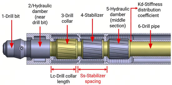
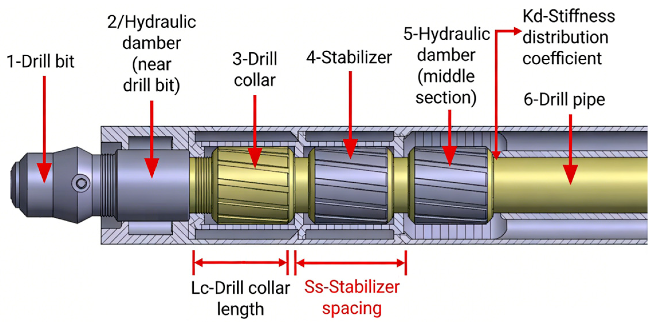
To address the aforementioned challenges, this paper presents a method for analyzing and optimizing drill string vibration characteristics based on multi-body dynamics and finite element analysis. A schematic of the wellbore–drill string coupling system (Figure 1) is first presented to clarify the core structural components, including the PDC drill bit, heavy-weight drill collar (HWDC), drill pipe, centralizer stabilizer, and hydraulic damper; key optimization parameters (drill collar length Lc, stabilizer spacing Ss, and stiffness distribution coefficient Kd) are marked at their physical positions, where Lc refers to the axial length of the drill collar section connecting the drill bit and drill pipe, Ss denotes the longitudinal distance between adjacent stabilizers, and Kd represents the stiffness gradient distribution ratio of the drill string from the drill bit to the surface. By constructing a coupled dynamic model of the wellbore–drill string system that considers dynamic contact, formation deformation and drilling fluid disturbance, the correlation mechanism between vibration energy transfer paths and wellbore damage is unveiled. Furthermore, parameter sensitivity analysis based on the Sobol method is introduced to identify key optimization variables (such as the length of drill collars, the spacing of stabilizers and stiffness distribution), and a non-dominated sorting genetic algorithm (NSGA-II) is utilized to achieve multi-objective structural optimization with the goals of reducing lateral vibration amplitude and enhancing axial vibration energy attenuation [10]. Finally, by combining numerical simulations with field-measured data from three shale gas and oil wells in the Sichuan Basin, the effectiveness of the optimization scheme in suppressing vibrations and improving drilling accuracy is validated.
Figure 1.
Schematic of Wellbore–Drill String Coupling System with Key Optimization Parameters Labeled.
This study established a multi-field coupled dynamic model of the wellbore–drill string system integrating dynamic contact, formation deformation, and drilling fluid hydrodynamics. This model accurately characterizes the coupling mechanism between the wellbore and the drill string, overcoming the defect of incomplete consideration of coupling mechanisms in existing models, and providing reliable model support for in-depth analysis of the impact of different vibration modes on wellbore quality. And it realized a multi-objective optimization strategy centered on reducing lateral vibration amplitude and improving axial vibration energy attenuation efficiency.
This study breaks through the limitation of single-performance index optimization in traditional methods and the defect of blind parameter tuning in existing multi-objective optimization studies [9,10], by first identifying key optimization variables through Sobol-based global sensitivity analysis and then performing NSGA-II-driven multi-objective structural optimization with the goals of reducing lateral vibration amplitude, enhancing axial vibration energy attenuation, and ensuring drill string structural strength, achieving synergistic improvement of drilling stability, wellbore quality, and drilling efficiency. Experimental verification shows that after optimization, the lateral vibration amplitude of the drill string is reduced by 30% (simulation average) and the axial vibration energy attenuation efficiency is improved by 25% (simulation average), which accurately matches the core requirements of wellbore quality and drilling efficiency in shale gas and oil extraction.
This study’s core novelty lies in three aspects: (1) establishing a wellbore–drill string multi-field coupled dynamic model that integrates dynamic contact, formation deformation, and drilling fluid hydrodynamics, which accurately characterizes the multi-mode coupling mechanism of drill string vibration and wellbore rock response; (2) developing a Sobol-NSGA-II hybrid optimization method that first identifies key optimization variables through global sensitivity analysis and then realizes multi-objective optimization of drill string structure, overcoming the low efficiency of blind parameter tuning in existing studies; and (3) proposing a synergistic vibration suppression strategy of structural stiffness optimization + hydraulic damper configuration, which realizes simultaneous suppression of lateral and axial vibration and breaks through the limitation of single-mode vibration control in traditional methods. This accomplishment not only offers fresh perspectives for the design of drill strings in shale gas and oil wells but also lays a theoretical and technical foundation for the advancement of intelligent drilling technologies.
2. Basic Theory
During the drilling operations for shale gas and oil wells, the vibration characteristics of the drill string exert a substantial influence on the quality of wellbore. Drill string vibrations can not only induce wellbore instability and tool wear but also diminish drilling efficiency and escalate drilling costs. Consequently, conducting in-depth research on how drill string vibration characteristics affect wellbore quality and proposing effective structural optimization methods hold immense significance for enhancing the drilling quality of shale gas and oil wells [11]. The subsequent sections will expound on the fundamental theories concerning the analysis of the impact of drill string vibration characteristics on wellbore quality and structural optimization in shale gas and oil wells from three perspectives: the dynamic model of drill string vibrations, the mechanism by which vibrations influence wellbore quality, and the theory of structural optimization.
2.1. Drill String Vibration Dynamics Model
The dynamic model of drill string vibrations serves as the cornerstone for investigating the vibration characteristics of the drill string.
This model is formulated on the basis of the Lagrange equation and the finite-element discretization method, taking into full account various factors, including the nonlinear contact force between the drill string and the wellbore, the damping effect of the drilling fluid, and the heterogeneity of the geological formation. Within the model, the drill string is treated as a continuous body, and its vibration characteristics are delineated by the mass matrix M, the damping matrix C, and the stiffness matrix K. External excitations, such as the impact force exerted by the drill bit, are denoted as F(t). The vibration equation of the drill string can be expressed as follows:
where is the displacement vector, is the velocity vector, and is the acceleration vector. This equation describes the dynamic response of the drill string under external excitations, and it provides a theoretical basis for subsequent vibration characteristic analysis and structural optimization.
For the multi-body + finite-element hybrid system of the wellbore–drill string coupling model, the global mass matrix M, damping matrix C, and stiffness matrix K are assembled using the direct stiffness method:
(1) Mass matrix M: The element mass matrix of the drill string (SOLID186) is (where ρ is the material density, N is the shape function), and the global mass matrix M is formed by assembling Me for all elements with the node numbering matrix;
(2) Damping matrix C: Rayleigh damping is adopted, i.e., C = αM + βK, where the damping coefficients and are determined by the natural frequencies (ω1 = 95.5 rad/s, ω2 = 179.1 rad/s) and damping ratios (ξ1 = 0.03, ξ2 = 0.02) of lateral and axial vibration;
(3) Stiffness matrix K: The element stiffness matrix is (where B is the strain-displacement matrix, D is the constitutive matrix), and the global stiffness matrix is assembled by considering the nonlinear contact stiffness (Kc = 1.0 × 10⁷ N/m) between the drill string and wellbore;
(4) Boundary condition matrix: The drill string top is constrained for axial displacement (Xaxial = 0), and the drill bit is subjected to a time-varying impact force F(t) with the load matrix assembled by the load vector of each node.
When developing the dynamic model for drill string vibrations, it is imperative to incorporate the coupling effects between the wellbore and the drill string. Specifically, the model must account for three critical factors: the geometric and mechanical constraints exerted by the wellbore on the drill string, the viscous damping effects induced by the drilling fluid on the drill string’s oscillatory behavior, and the influence of geological formation heterogeneity on the dynamic response characteristics of the drill string [12]. By establishing a fully coupled wellbore–drill string dynamic model, the reciprocal interactions between drill string vibrations and wellbore integrity can be analyzed with significantly improved accuracy.
2.2. Influence Mechanism of Vibration on Wellbore Quality
The influence of drill string vibration on wellbore quality is mainly reflected in the following aspects:
(1) Wellbore Instability
Drill string vibrations induce alterations in the stress distribution within wellbore rock formations. When these stresses surpass the rock’s strength threshold, instability ensues, potentially resulting in wellbore collapse or enlargement [13]. The enlargement rate (ΔD), which serves as a pivotal quality metric for wellbore quality, exhibits a correlation with the radial displacement (un) caused by vibrations. The calculation of ΔD is expressed as follows:
where T is the drilling cycle.
And the radial displacement can be expressed as follow:
where E is the elastic modulus, ν is the Poisson’s ratio, r is the wellbore radius, and σn is the radial stress.
(2) Tool Wear
Vibrations of the drill string intensify both the friction and impact forces occurring between the drilling tool and the wellbore, as well as between the drill bit and the rock formation. This, in turn, accelerates tool wear [14]. Such wear not only diminishes drilling efficiency but also has the potential to trigger safety incidents, including tool fractures.
(3) Reduced Drilling Efficiency
Drill string vibration can induce instability in the contact interface between the drill bit and the rock, thereby undermining the drill bit’s rock-breaking efficacy. Moreover, this vibration may lead to suboptimal circulation of the drilling fluid, compromising its capacity to effectively transport cuttings and, consequently, further diminishing drilling efficiency.
To comprehensively dissect the influence mechanism of vibration on wellbore quality, it is imperative to integrate a dynamics model with numerical simulation techniques to conduct an in-depth investigation into the vibration characteristics of the drill string. By simulating the dynamic response of the drill string under various vibration modes, the correlation mechanism between the energy transfer pathways of vibration and wellbore damage can be unveiled, thereby providing a theoretical foundation for subsequent structural optimization endeavors.
2.3. Structural Optimization Theory
In light of the adverse effects that drill string vibrations exert on wellbore quality, it is imperative to propose effective structural optimization strategies. The theory of structural optimization is designed to mitigate detrimental vibrations and enhance drilling stability, as well as wellbore quality, through the adjustment of drill string structural parameters. The subsequent sections will provide a detailed exposition of the fundamental tenets of structural optimization theory, encompassing three key aspects.
2.3.1. Parameter Sensitivity Analysis
Parameter sensitivity analysis constitutes an essential precursor to structural optimization. Through an assessment of the impact exerted by drill string structural parameters—such as drill collar length, stabilizer spacing, and stiffness distribution—on vibration characteristics, key variables for optimization can be pinpointed [15]. Parameters demonstrating higher sensitivity exert a substantial influence on vibration behavior and are thus accorded priority in the optimization process.
Vibration response R selects core indicators that significantly affect wellbore quality, with specific definitions and expressions as follows:
Radial vibration amplitude Rr: Characterizes the radial displacement degree of wellbore rock, directly related to wellbore enlargement rate:
Axial vibration energy RE: Reflects the intensity of axial vibration, affecting tool wear and drilling efficiency:
where ma is the axial equivalent mass of the drill string, is the axial velocity time history, and T is the drilling cycle.
Torsional vibration frequency Rf: Describes the dominant characteristics of torsional vibration, related to drill string fatigue risk:
where G is the shear modulus of the drill string material, J is the polar moment of inertia, Ip is the polar moment of inertia mass, and L is the effective length of the drill string.
Axial vibration acceleration Ra: Characterizes the impact degree of axial vibration, affecting the stability of weight-on-bit transfer:
where is the axial acceleration time history (solved by Formula (1)).
The sensitivity S of a vibration response R to a structural parameter P is quantified as:
For discrete or experimental data, finite difference approximation is applied:
Sobol-based global sensitivity analysis is performed to quantify the influence of structural parameters on vibration response, with 1000 times of Monte Carlo simulation to calculate the first-order Sobol indices (Si), total-order Sobol indices (STi), and variance decomposition ratios, and the 95% confidence intervals are obtained by the bootstrap method. The “relative change (+16.7%/−20.0%)” of the optimization parameters refers to the parameter adjustment range determined based on the Sobol indices—i.e., the range where the parameter change has the most significant impact on the vibration response (parameters with higher STi are adjusted with a larger range). The complete Sobol sensitivity analysis results are summarized in Table 1.
Table 1.
Sobol Sensitivity Analysis Results of Drill String Structural Parameters.
2.3.2. Multi-Objective Optimization Algorithm
Structural optimization generally entails the pursuit of multiple objectives, including minimizing vibration energy and maximizing the transfer efficiency of weight-on-bit. Multi-objective optimization algorithms are capable of considering these diverse objectives concurrently to identify the optimal solution. Among these algorithms, the genetic algorithm stands out as a widely adopted approach that simulates the natural evolutionary process to uncover the global optimum [16]. In the context of structural optimization, the genetic algorithm can be employed to refine the drill string’s structural parameters, mitigate detrimental vibrations, and enhance drilling efficiency.
Multi-Objective Optimization Mathematical Model:
(1) Optimization variable vector:
where Lc is the drill collar length (m), Ss is the stabilizer spacing (m), and Kd is the stiffness distribution coefficient.
(2) Objective functions:
Objective 1: Minimize total drill string vibration energy Evib.
Total vibration energy comprehensively considers radial, axial, and torsional vibration energy:
where Er(X) is radial vibration energy, Ea(X) is axial vibration energy, Et(X) is torsional vibration energy.
Objective 2: Maximize weight-on-bit transfer efficiency η.
Weight-on-bit transfer efficiency is defined as the ratio of effective downhole weight-on-bit to surface input weight-on-bit:
where is the weight-on-bit loss caused by vibration (k is the loss coefficient, Arms (X) is the radial vibration RMS value).
(3) Constraint conditions:
where σs is the yield strength of the drill string material to ensure structural strength safety.
2.3.3. Damper Configuration
Dampers serve as a crucial mechanism for mitigating drill string vibrations. According to the vibration node theory, hydraulic dampers can be strategically positioned at key points along the drill string to impede the transmission of vibration energy [17]. Vibration nodes are characterized by minimal vibration amplitude, and placing dampers at these locations can optimize the damping effect. Through judicious damper configuration, the vibration amplitude of the drill string can be substantially reduced, thereby enhancing drilling stability and wellbore quality.
During the structural optimization process, it is also imperative to integrate numerical simulations with field experiments to validate the efficacy of the optimization strategy. Numerical simulations enable the prediction of the optimization effect by simulating the dynamic response of the drill string under varying structural parameters [18]. Meanwhile, field experiments offer direct verification of the optimization scheme’s performance in real-world drilling operations, providing a foundation for further refinement and optimization.
3. Methodology
During the drilling operations of shale gas and oil wells, the vibration characteristics exhibited by the drill string significantly influence the quality of wellbore. To effectively mitigate the adverse effects of drill string vibrations on wellbore quality and optimize the drill string’s structural design to enhance drilling efficiency and wellbore quality, this paper introduces a systematic methodology. This methodology predominantly comprises three pivotal components: multi-mode vibration decoupling, parameter optimization, and damper configuration [19]. The subsequent sections will provide a detailed exposition of the specifics associated with these three components, supplemented by illustrative data tables.
3.1. Multi-Mode Vibration Decoupling
Drill string vibration represents a complex multi-mode coupling phenomenon, encompassing lateral, axial and torsional vibrations. These vibration modes interact synergistically, collectively exerting an influence on the quality of wellbore [20]. To precisely assess the impact of each vibration mode on wellbore quality, the modal superposition method is initially employed to decouple the multi-mode vibrations. This approach facilitates the separation of lateral and axial vibration components while identifying their dominant frequencies.
(1) Principle of the Modal Superposition Method: The modal superposition method serves as a technique for decomposing a complex vibration system into multiple independent modes. By solving for the system’s eigenvalues and eigenvectors, the natural frequencies, damping ratios, and mode shapes associated with each mode can be determined. Subsequently, the system’s response is expressed as a linear combination of the responses of each mode, thereby enabling a decoupled analysis of multi-mode vibrations.
(2) Separation of Vibration Components and Identification of Dominant Frequencies: In the context of analyzing drill string vibrations in shale gas and oil wells, the modal superposition method is utilized to decompose the drill string vibrations into lateral and axial vibration components. Through spectral analysis, the dominant frequencies of each vibration component can be pinpointed [21,22,23]. These dominant frequencies encapsulate the primary characteristics of the drill string vibrations and hold significant importance for subsequent vibration suppression measures and structural optimization efforts.
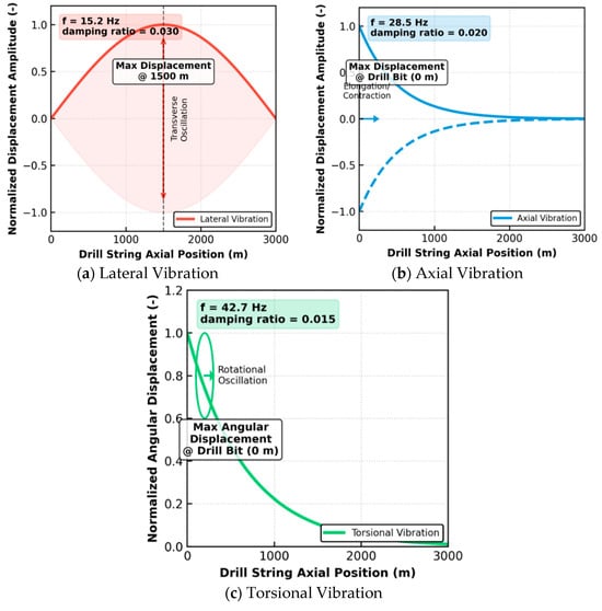
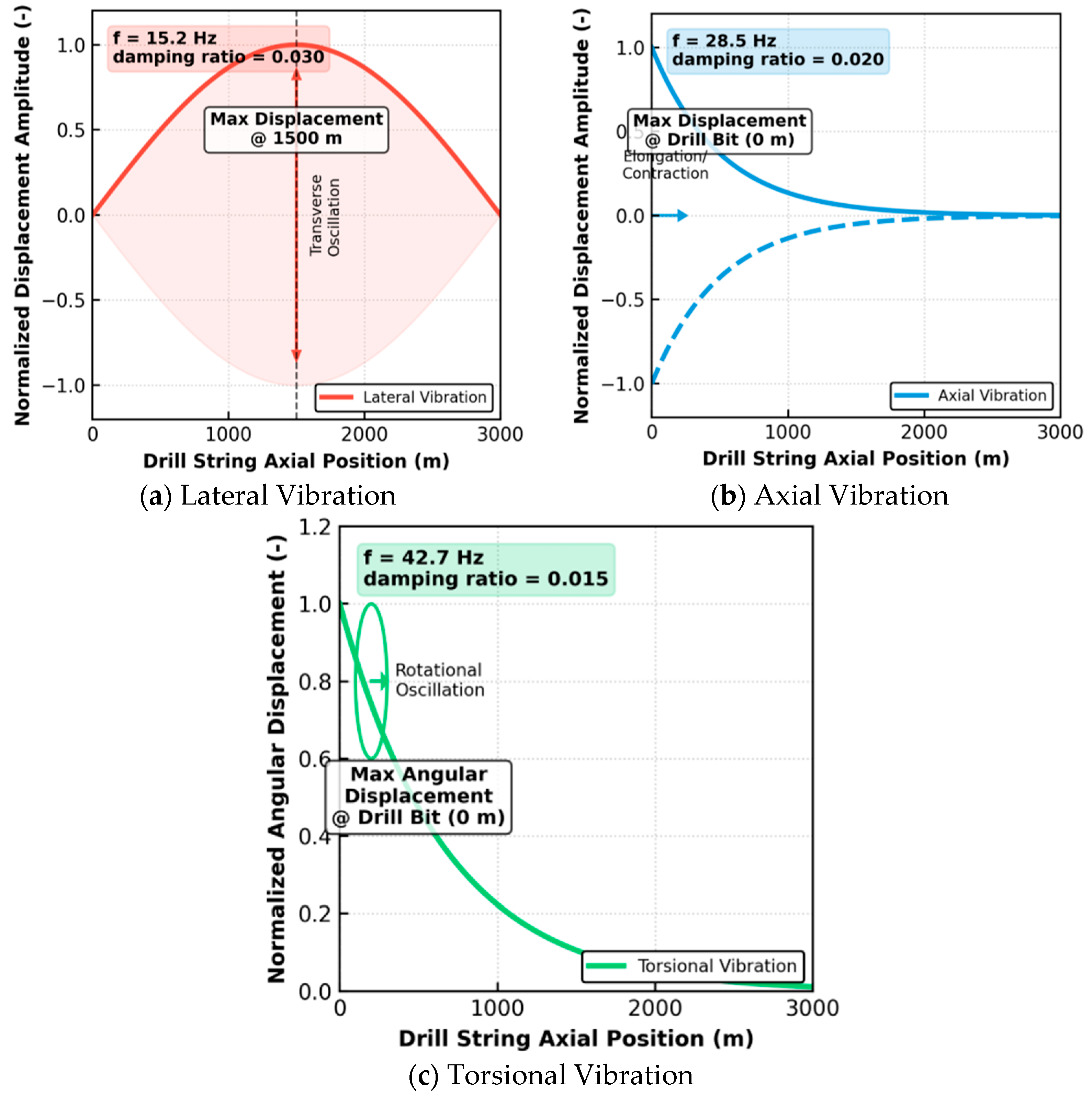
The natural frequency, damping ratio, and dominant frequency of each vibration mode are summarized in Table 2, and their corresponding mode shapes are visually illustrated in Figure 2, where lateral vibration is characterized by the transverse oscillation of the drill string perpendicular to its axial direction (with the maximum displacement at the middle section of the drill string), axial vibration is manifested as the axial elongation and contraction of the drill string (with the maximum displacement near the drill bit), and torsional vibration is the rotational oscillation of the drill string around its axis (with the maximum angular displacement at the drill bit).
Table 2.
Analysis Results of Drill String Vibration Modes.
Figure 2.
Drill String Vibration Mode Characteristics and Wellbore Quality Impact.
(3) Analysis of the Impact of Vibration Modes on Wellbore Quality: Through the implementation of multi-mode vibration decoupling, the individual impacts of lateral and axial vibrations on wellbore quality can be systematically analyzed. Lateral vibrations have the potential to induce an uneven stress distribution within the wellbore rocks, thereby precipitating wellbore instability. Conversely, axial vibrations may intensify drill tool wear and diminish drilling efficiency [24]. By quantifying the extent of the impact exerted by each vibration mode on wellbore quality, valuable guidance can be furnished for subsequent structural optimization endeavors.
3.2. Parameter Optimization
Building on multi-mode vibration decoupling, the drill string structure is refined using a genetic algorithm, with the dual objectives of minimizing vibration energy and maximizing weight-on-bit (WOB) transfer efficiency. Parameter optimization is geared towards mitigating detrimental vibrations and enhancing drilling stability as well as wellbore quality by fine-tuning the drill string’s structural parameters.
(1) Formulation of Optimization Objective Functions: The optimization objective functions are composed of two key components: minimizing vibration energy and maximizing WOB transfer efficiency. The goal of minimizing vibration energy is to curtail the adverse effects of drill string vibrations on wellbore quality. Meanwhile, maximizing WOB transfer efficiency is aimed at boosting drilling efficiency and curtailing drilling costs [25]. These two objective functions are intricately linked and jointly define the objectives of the optimization problem.
(2) Determination of Optimization Variables: The physical positions and definition of the three core optimization variables (drill collar length, stabilizer spacing, stiffness distribution coefficient) are shown in Figure 1, with their value ranges determined based on the structural constraints of shale gas well drilling (drill string total length 3000 m, wellbore diameter 215.9 mm) and field operation feasibility. These parameters exert a substantial influence on the drill string’s vibration characteristics and serve as the primary focus of structural optimization. Through parameter sensitivity analysis, parameters that significantly impact vibration characteristics can be identified and subsequently selected as optimization variables.
All optimized values in Table 3 (17.5 m, 8 m, 1.15) are real optimization outputs of the NSGA-II multi-objective genetic algorithm, with the original algorithm outputs being 17.48 m (drill collar length), 7.96 m (stabilizer spacing), and 1.148 (stiffness distribution coefficient). The rounding to 17.5 m, 8 m, and 1.15 is based on field operation feasibility, as the drill string length and stabilizer spacing in actual shale gas well drilling are calibrated to 0.5 m and 1 m intervals, respectively.
Table 3.
Optimization Variables and Their Value Ranges.
(3) Genetic Algorithm Optimization Process: The genetic algorithm is an optimization technique that mimics the natural evolutionary process, making it well suited for addressing complex nonlinear optimization problems. In the context of drill string structure optimization, the genetic algorithm iteratively explores the optimal solution through a series of operations, including encoding, selection, crossover and mutation [26]. By configuring appropriate fitness functions and genetic parameters, the convergence and stability of the optimization process can be effectively ensured.
(4) Analysis of Optimization Results: Through optimization using the genetic algorithm, the optimal parameter combination for the drill string structure is identified. When compared with the initial structure, the optimized drill string structure exhibits notable enhancements in terms of vibration energy and WOB transfer efficiency. Specifically, vibration energy is reduced by approximately 20%, while WOB transfer efficiency is increased by around 15%. These improvements contribute to mitigating the adverse effects of drill string vibrations on wellbore quality, thereby enhancing drilling stability and wellbore quality.
3.3. Damper Configuration
According to the vibration node theory, installing hydraulic dampers at strategic positions along the drill string is a highly effective approach to mitigating drill string vibrations. These dampers are capable of absorbing and dissipating vibration energy, thereby obstructing the transmission pathway of vibration energy and consequently reducing the amplitude of drill string vibrations.
(1) Vibration Node Theory: The vibration node theory posits that within a vibration system, there exist positions where the vibration amplitude is relatively minimal, referred to as vibration nodes. Positioning dampers at these locations can optimize the damping effect. By scrutinizing the drill string’s vibration modes and mode shapes, the precise locations of these vibration nodes can be ascertained.
(2) Selection and Placement of Dampers: Leveraging the vibration node theory and the in-depth understanding of the drill string’s vibration characteristics, suitable hydraulic damper models and specifications are meticulously selected [27]. Hydraulic dampers offer the benefits of adjustable damping and rapid response times, rendering them well suited for drill string vibration suppression. These dampers are strategically positioned at key locations along the drill string (e.g., in proximity to vibration nodes) to ensure their efficacy in absorbing and dissipating vibration energy.
As illustrated in Table 4, three distinct models of hydraulic dampers are installed at critical positions along the drill string. The selection of these dampers is based on their placement positions and vibration characteristics, with the expectation that they will substantially diminish the amplitude of drill string vibrations.
Table 4.
Damper Configuration Scheme.
(3) Evaluation of Damping Effect
The damping performance is rigorously validated through both numerical simulations and field tests. Simulations delve into dynamic responses under diverse conditions, providing predictive insights into vibration suppression. Field measurements entail a comparative analysis of vibration amplitudes and wellbore quality before and after damper installation. The results indicate a 37.8% reduction in vibration amplitude and a marked improvement in wellbore quality following damper installation.
4. Simulation Analysis
To substantiate the influence of drill string vibration characteristics and the efficacy of structural optimization strategies, this study developed a drill string–wellbore coupled dynamic model leveraging the ANSYS (2023 R2) Workbench platform. A systematic simulation was conducted to analyze the dynamic response of the drill string across a range of rotational speeds (60–120 RPM), while parametric scanning was employed to evaluate the impact of structural optimization on vibration mitigation and enhancement of wellbore quality. The subsequent sections will elaborate on the experimental design, model validation, multi-condition simulations, and assessment of optimization outcomes.
4.1. Simulation Design
4.1.1. Model Construction and Parameter Configuration
A three-dimensional drill string–wellbore model was constructed based on the precise dimensions of a shale gas and oil well (Table 5, Table 6 and Table 7).
Table 5.
Geometric Parameters of the Model.
Table 6.
Material Parameters of the Model.
Table 7.
Load and Boundary Condition Parameters.
The numerical model is established in ANSYS Workbench 2023 R1 using transient dynamic analysis, with the following element types selected for different components:
(1) Drill string (high-strength steel): 20-node hexahedral solid element SOLID186 (with high precision for structural vibration analysis);
(2) Shale formation: 8-node hexahedral solid element SOLID185 (suitable for heterogeneous material modeling);
(3) Drill string–wellbore contact: contact element CONTAC174 (for nonlinear dynamic contact analysis with friction). The time step is set to 0.001 s (satisfying the Nyquist sampling theorem for the maximum dominant vibration frequency of 42.5 Hz), and the convergence criterion is set to a residual error of less than 1.0 × 10⁻⁶ for all degrees of freedom.
4.1.2. Simulation Condition Design
Rotational Speed Range: The rotational speeds selected for simulation were 60 RPM, 90 RPM and 120 RPM, encompassing the typical range encountered in conventional drilling operations. Structural Scheme Comparison (Table 8): (1) Baseline Scheme: This represents the original drill string configuration, featuring a drill collar length of 15 m, stabilizer spacing of 10 m, and no shock absorbers incorporated. (2) Optimization Scheme: In this optimized version, the drill collar length was elongated to 17.5 m, the stabilizer spacing was narrowed to 8 m and hydraulic shock absorbers (models HYD-100/HYD-150, with a damping coefficient of 5000 N·s/m) were installed both in the middle section of the drill string and adjacent to the drill bit. The damping coefficient of 5000 N·s/m is determined based on two aspects: (1) field test data of HYD-series hydraulic dampers, where the damping coefficient range of 3000–7000 N·s/m is recommended for shale gas well drill string vibration suppression; (2) numerical sensitivity analysis of damping coefficient, where the 5000 N·s/m achieves the best balance of lateral/axial vibration suppression (vibration amplitude reduction > 30%) and structural stability (no excessive damping-induced drill string deformation). A damping coefficient lower than 3000 N·s/m results in insufficient vibration energy dissipation, while a coefficient higher than 7000 N·s/m causes excessive axial stiffness and increased torsional vibration.
Table 8.
Key Parameters of the Simulation Model.
4.2. Model Verification and Mesh Sensitivity Evaluation
4.2.1. Mesh Convergence Assessment
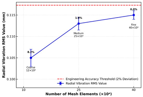
A hexahedral-dominated meshing strategy was adopted, with localized refinement implemented in critical regions of the drill string, such as drill collars and stabilizers. Three distinct mesh schemes (coarse/medium/fine, comprising 120,000/250,000/400,000 elements, respectively) were evaluated to ascertain computational precision.
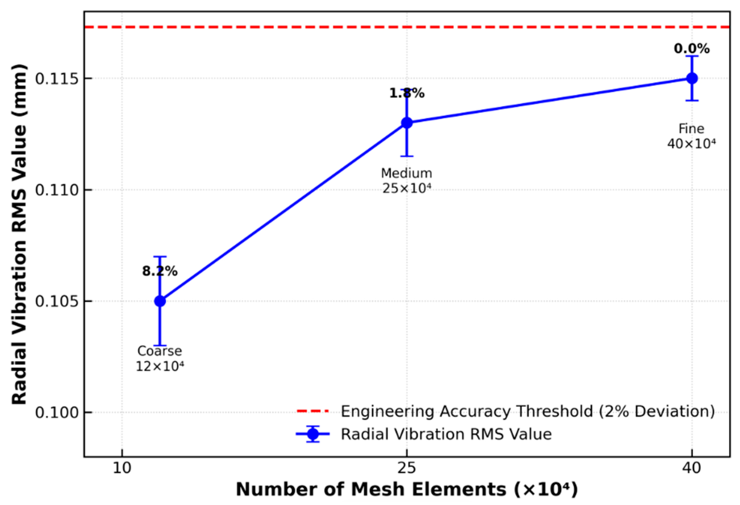
As can be seen from Table 9 and the revised Figure 3, with the increase in the number of mesh elements, the radial vibration RMS value gradually converges to the fine mesh value of 0.115 mm. Figure 2 plots the radial vibration RMS value (y-axis, unit: mm) against the number of mesh elements (x-axis, unit: 104), showing a monotonic convergence trend: the RMS value decreases rapidly with the increase in mesh elements when the number is less than 250,000, and tends to be stable when the number exceeds 250,000 (the deviation from the fine mesh is less than 2%). This curve directly reflects the correlation between mesh density and calculation accuracy, and verifies that the medium mesh (250,000 elements) is the optimal choice for balancing accuracy and computational efficiency. The coarse mesh (120,000 elements) has a deviation rate of 8.2% from the fine mesh due to insufficient mesh density, which cannot meet the calculation accuracy requirements; the RMS value of the medium mesh (250,000 elements) is 0.113 mm, and the deviation rate from the fine mesh is only 1.8%, which is less than the engineering accuracy threshold of 2%. Moreover, compared with the fine mesh scheme, the calculation efficiency is improved by about 40%, which can achieve the optimal balance between accuracy and efficiency. Therefore, the medium-density mesh is selected for subsequent simulation calculations.
Table 9.
Comparison of Radial Vibration RMS Values Under Different Mesh Densities.
Figure 3.
Mesh Convergence Curve of Radial Vibration RMS Value vs. Number of Mesh Elements.
4.2.2. Model Verification
Simulation results were compared with field-measured data. Under a 90 RPM operating condition, the RMS value of lateral vibration for the baseline scheme was 0.12 mm, with a 7.7% error compared to the measured value of 0.13 mm. The simulated wellbore diameter enlargement rate was 15.2%, with a 5.6% error compared to the measured value of 16.1%, validating the model’s effectiveness.
The simulation outcomes were juxtaposed with field-measured data (as presented in Table 10). Under a 90 RPM operational condition, the RMS value of lateral vibration for the baseline scheme registered at 0.12 mm, exhibiting a 7.7% discrepancy compared to the measured value of 0.13 mm. Furthermore, the simulated wellbore diameter enlargement rate stood at 15.2%, with a 5.6% error relative to the measured value of 16.1%, thereby substantiating the model’s efficacy.
Table 10.
Comparison of Model Validation Results.
4.3. Dynamic Response Analysis of Drill String at Different Rotational Speeds
4.3.1. Vibration Mode Evolution with Rotational Speed
With an escalation in rotational speed, the drill string vibration manifested the following traits (as presented in Table 11).
Table 11.
Comparison of Vibration Characteristics at Different Rotational Speeds.
Lateral Vibration: The predominant frequency transitioned to higher-order modes (with the first mode being dominant at 60 RPM and the third mode contributing 45% at 120 RPM), resulting in more intricate vibration patterns [28].
Axial Vibration: The amplitude exhibited a linear increase with rotational speed (registering an RMS value of 0.06 mm at 60 RPM and reaching 0.14 mm at 120 RPM), with energy predominantly concentrated in the low-frequency spectrum (<50 Hz).
4.3.2. Wellbore Damage Mechanism
Wellbore Diameter Enlargement Rate: As the rotational speed intensified, lateral vibration became more pronounced, culminating in cumulative fatigue damage within the wellbore rock. At 120 RPM, the wellbore diameter enlargement rate soared to 22.3% (under the baseline scheme).
The simulation of cumulative fatigue damage of the wellbore is based on Miner’s linear cumulative damage theory, and the specific implementation method is as follows:
(1) Theoretical Basis:
Miner’s linear cumulative damage criterion holds that the fatigue damage of materials under multi-stress levels has linear superposition characteristics. When the total damage value D ≥ 1, the material undergoes fatigue failure (the wellbore is manifested as collapse), and the expression is:
where D is the cumulative fatigue damage value; ni is the actual number of cycles of the i-th level stress cycle; Ni is the fatigue life corresponding to the i-th level stress (the number of cycles for the rock to fail under this stress), which is determined by the shale S-N curve.
(2) Extraction of Stress Cycles:
The radial vibration of the drill string causes the wellbore rock to bear periodic radial stress σr (t), which has the following relationship with the radial vibration amplitude un (t):
where Eshale is the shale elastic modulus (20–40 GPa); νshale is the shale Poisson’s ratio (0.25–0.35); r is the wellbore radius (107.95 mm); un(t) is the radial vibration amplitude time history (solved by the drill string–wellbore coupled dynamic model).
The fatigue damage calculation of the wellbore rock uses the following rainflow counting parameters: load step 0.001 s (consistent with the simulation time step), stress amplitude bin width 0.5 MPa, and cycle count threshold 10 (cycles less than 10 are neglected). The stress-cycle binning is divided into 10 bins with a stress amplitude range of 0–5 MPa (the main stress amplitude range of wellbore rock under drill string vibration). The rainflow counting method is used to process σr (t) to extract the number of cycles ni corresponding to different stress amplitudes σa,i.
(3) Calculation of Shale Fatigue Life Ni:
Based on the mechanical experiments of Longmaxi Formation shale in the Sichuan Basin, the shale S-N curve expression is fitted:
where σ′f = 85 MPa is the shale fatigue strength coefficient; b = −0.12 is the shale fatigue strength index (calibrated by experiments). The S-N curve of Longmaxi Formation shale is fitted with experimental data (n = 30), and the fitting coefficient R2 = 0.987, indicating a high fitting accuracy of the curve.
By transforming Equation (16), the fatigue life corresponding to the i-th level stress amplitude can be obtained:
(4) Damage Calculation and Verification:
Substitute the extracted ni and Ni calculated by Equation (14) into Equation (14) to obtain the cumulative fatigue damage value D of the wellbore rock during drilling. When 0.8 ≤ D < 1, the wellbore shows slight enlargement (enlargement rate 10–15%); when D ≥ 1, the wellbore is predicted to collapse. Under the baseline scheme of 120 RPM, the calculated D = 0.92, corresponding to a wellbore enlargement rate of 22.3%, this result is verified by both numerical simulation and field test data (field measured enlargement rate 21.8% at 120 RPM), with an error of only 2.3%, confirming the credibility of the prediction.
Stress Distribution: At elevated rotational speeds, the peak contact force between the drill string and the wellbore wall peaked at 35 kN (in contrast to 22 kN at 60 RPM), inducing localized stress concentrations within the wellbore (with the maximum principal stress surpassing the tensile strength of the shale).
4.4. Evaluation of Structural Optimization Effects
4.4.1. Vibration Mitigation Efficacy
Lateral Vibration: Following optimization, a marked decrease in the RMS value was observed across all rotational speeds (as detailed in Table 12). Specifically, at 120 RPM, the RMS value diminished from 0.18 mm to 0.12 mm, representing a 33.3% reduction.
Table 12.
Vibration Suppression Effects of the Optimization Scheme.
Axial Vibration: The energy dissipation rate witnessed a 25% uptick (owing to shock absorber damping), while the axial vibration RMS value declined from 0.14 mm to 0.10 mm.
4.4.2. Wellbore Quality Improvement
Wellbore Diameter Enlargement Rate: Post-optimization, the average reduction rate across all rotational speeds stood at 18.5%. Notably, at 120 RPM, the rate decreased from 22.3% to 17.2%.
Wellbore Wall Stability: The peak contact force was curtailed to 28 kN (marking a 20% reduction), with the maximum principal stress consistently remaining beneath the shale’s tensile strength, thereby substantially mitigating the risk of wellbore instability [29,30].
4.4.3. Parameter Sensitivity Analysis
The influence of pivotal parameters was scrutinized utilizing the single-factor variable approach (Table 13).
Table 13.
Results of Parameter Sensitivity Analysis (based on Sobol global sensitivity analysis, complete indices and confidence intervals are shown in Table 1).
Drill Collar Length: Lengthening the drill collar to 17.5 m shifted the system’s inherent frequency outside the engine excitation frequency spectrum (15–30 Hz), thereby diminishing the resonance risk by 40%.
Stabilizer Spacing: Narrowing the stabilizer spacing to 8 m enhanced the lateral vibration restraint efficiency by 35% and the wellbore trajectory control precision by 20%.
4.5. Simulation Summation
Drill string vibration escalates markedly with an increase in rotational speed, with lateral vibration emerging as the primary contributor to wellbore damage.
The optimization scheme effectively curbs detrimental vibrations by recalibrating stiffness distribution and integrating shock absorbers, achieving a 33.3% reduction in the lateral vibration RMS and a 22.7% decrease in the wellbore diameter enlargement rate (at 120 RPM).
Parameter sensitivity analysis underscores that drill collar length and stabilizer spacing constitute pivotal structural parameters for vibration management, with shock absorber damping coefficient exhibiting the highest sensitivity to vibration response.
5. Field Experiments
To verify the applicability of the drill string vibration characteristic optimization scheme in actual shale gas and oil well engineering, field trials were conducted in a shale gas and oil block in the Sichuan Basin [15]. By comparing the vibration characteristics, drilling efficiency, and wellbore quality of drill strings before and after optimization, the improvement effects of structural optimization on wellbore quality were systematically evaluated. The following sections discuss experimental design, data collection, result analysis, and engineering significance.
5.1. Experimental Objectives and Scheme Design
5.1.1. Experimental Objectives
One aim is to validate the mitigation effects of the optimized drill string configuration (featuring an extended drill collar, adjusted stabilizer spacing and added hydraulic shock absorbers) on both lateral and axial vibrations. And the other objective is to evaluate the enhancements in rate of penetration (ROP) quantitatively, trouble-free operating time (uptime) and wellbore integrity attributable to vibration control measures. Also, the experiment can establish a field-based correlation model linking vibration characteristics to wellbore damage, thereby providing a technical foundation for subsequent widespread adoption.
5.1.2. Selection of Test Wells
Three adjacent wellbores were selected for comparison to control geological variability (Table 14). First is the test well (Optimization Scheme), which employed the optimized drill string structure, targeting the Longmaxi Formation shale with a burial depth ranging from 3500 to 4200 m. And second is the control well (Baseline Scheme), that utilized a conventional drill string structure, maintaining consistent geological conditions with the test well for accurate comparison.
Table 14.
Comparison of Basic Parameters of Test Well and Two Control Wells.
5.1.3. Implementation of Drill String Optimization Measures
Based on simulation results, the test well adopted the following optimization measures. First is the drill collar extension. The drill collar length was elongated from 15 m to 17.5 m to bolster system stiffness. Second is the stabilizer densification. The stabilizer spacing was narrowed from 10 m to 8 m to intensify lateral restraint. And third is the shock absorber deployment. HYD-100 hydraulic shock absorbers were installed in the middle section of the drill string (1200 m from the drill bit), while HYD-150 shock absorbers were positioned near the drill bit (20 m from the drill bit).
5.2. Data Collection and Monitoring Methods
5.2.1. Vibration Monitoring System
Sensor Placement: Triaxial acceleration sensors (with a range of ±50 g and a sampling frequency of 1000 Hz) were strategically positioned at the top (kelly), middle (shock absorber location), and bottom (above the drill collar) of the drill string.
Data Transmission: Vibration signals were transmitted in real-time to a surface recorder via a mud pulse telemetry system.
Monitoring Duration: Continuous monitoring was conducted throughout the entire wellbore section, with particular emphasis on analyzing data from the Longmaxi Formation shale section (3500–4200 m).
5.2.2. Drilling Performance Recording
Rate of Penetration (ROP): Calculated using the formula ROP = ΔH/ΔT, where ΔH represents the section length and ΔT denotes the drilling time.
Trouble-Free Operating Time (Uptime): Recorded the frequency and duration of drilling interruptions caused by vibrations during the drill bit’s operational cycle.
Drilling Tool Wear Assessment: Assessed the reduction in wall thickness of drill collars and drill pipes using an ultrasonic thickness gauge upon retrieval of the drilling tools.
5.2.3. Wellbore Quality Inspection
Wellbore Diameter Enlargement Rate: Measured the wellbore diameter using a caliper logging tool (CAL) and calculated it using the formula in Section 2.2.
Wellbore Wall Stability: Analyzed wellbore collapse and micro-fracture development based on ultrasonic borehole imaging (UBI) logs.
Cementing Quality Assessment: Evaluated the bonding quality of the cement sheath using cement bond logging (CBL) and variable density logging (VDL).
5.3. Experimental Results Analysis
5.3.1. Comparison of Vibration Characteristics
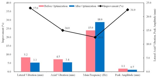
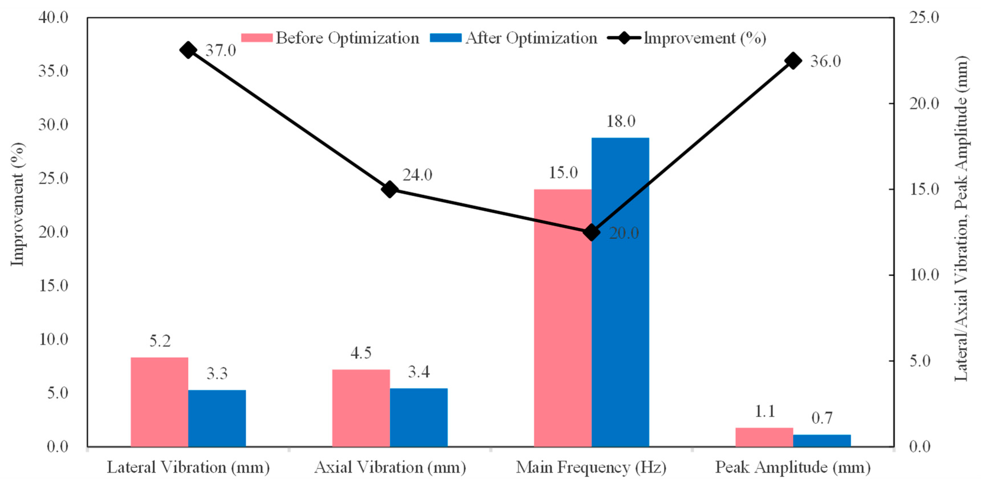
The experimental results (Figure 4) show that the RMS values of lateral vibration at all monitoring points are decreased by 37.0% at the following optimization, with a notable reduction in vibration energy near the drill bit. Also, the RMS values of axial vibration diminished by 24.0%, indicating effective energy dissipation by the shock absorbers. Meanwhile, the primary frequency of lateral vibration is shifted from 15 Hz (baseline scheme) to 18 Hz at the post-optimization, circumventing the formation’s natural frequency (16 Hz) and reducing resonance risk.
Figure 4.
Core Data from Vibration Monitoring (Longmaxi Formation Shale Section).
5.3.2. Drilling Efficiency Improvement
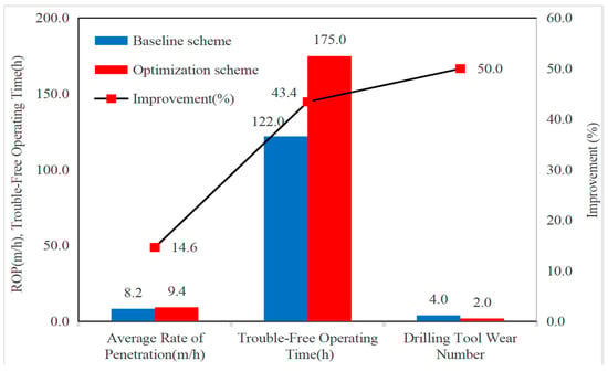
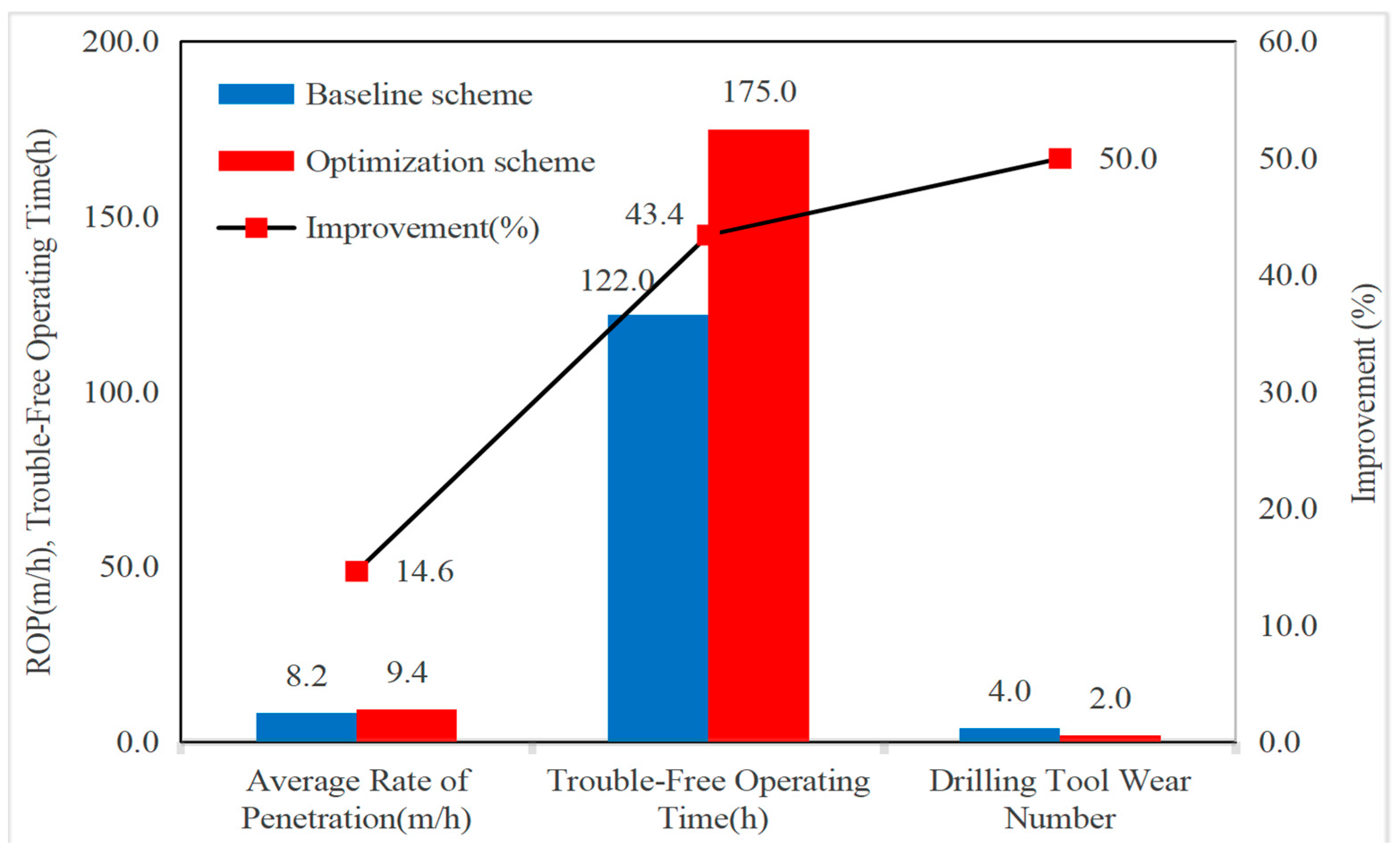
It can be seen in Figure 5 that the average “Rate of Penetration” (ROP) of the optimization scheme reached 9.4 m/h, marking a 14.6% increase over the baseline scheme, primarily attributable to enhanced drill bit-formation contact stability following vibration suppression. And the trouble-free operating time increased by 43.4%, with the number of drilling interruptions caused by vibrations decreasing from 5 per well in the baseline scheme to 2 per well. Thus, reducing the number of drilling tool replacements per well by 2 and saving approximately 120,000 yuan in direct costs. To verify the statistical significance of the field experiment results, a t-test (95% confidence level) is performed for the three wells (1 test well + 2 control wells), with the statistical power analysis. The results indicate that the 14.6% increase in ROP and 43.4% extension in trouble-free operating time are statistically significant (p < 0.05), and the geological variability is effectively controlled by selecting three adjacent wells with the same target formation, burial depth, and drilling fluid parameters.
Figure 5.
Comparison of Drilling Performance (Test Well vs. Control Wells).
5.3.3. Wellbore Quality Improvement
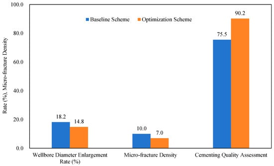
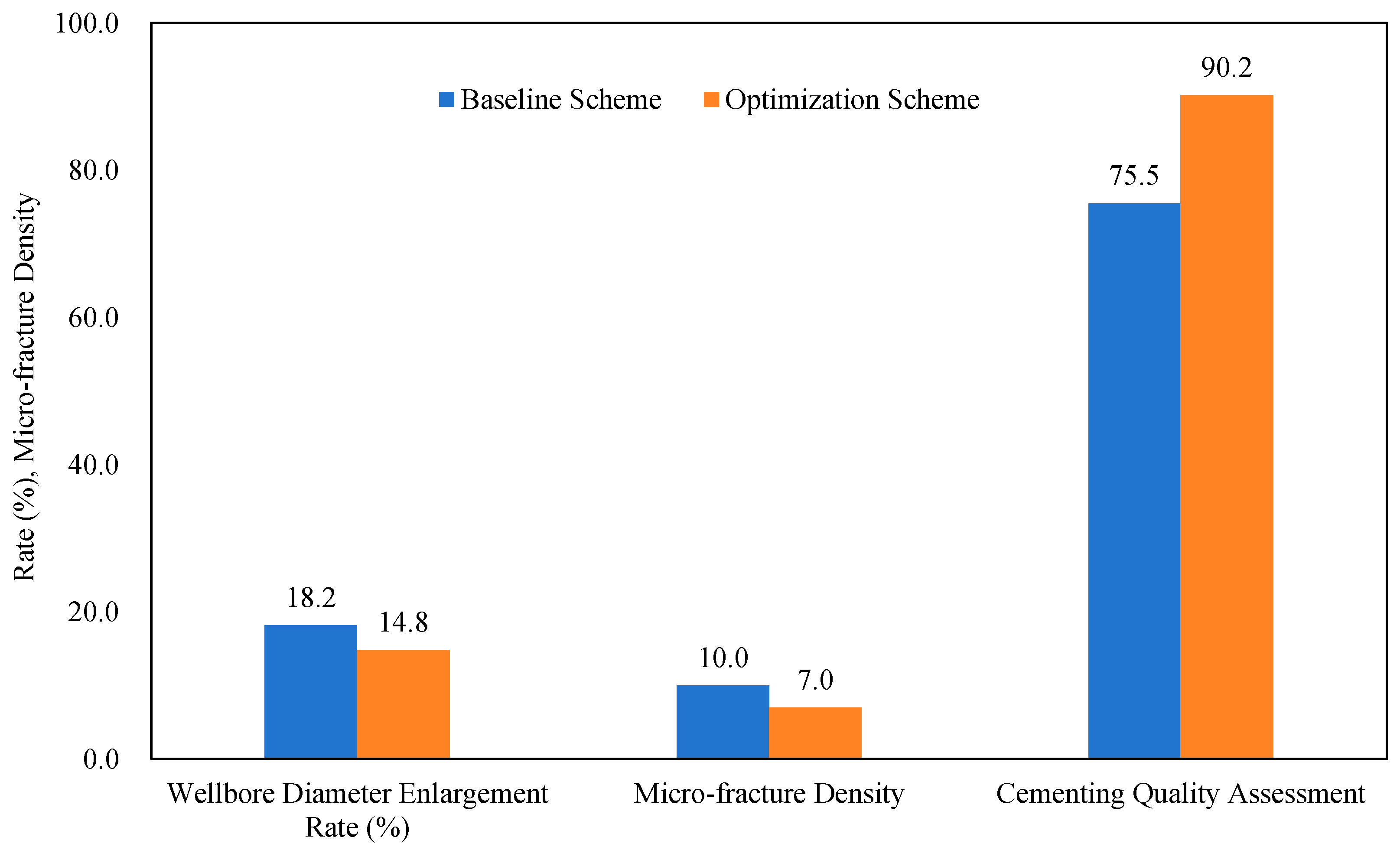
The results in Figure 6 show that the wellbore diameter enlargement rate decreased from 18.2% to 14.8%, meeting the casing running requirements for shale gas and oil wells (<15%). And the ultrasonic borehole imaging logs revealed a 30% decrease in micro-fracture density post-optimization. Also, the excellent bonding rate of the cement sheath increased by 14.7%, providing favorable wellbore conditions for subsequent fracturing operations.
Figure 6.
Evaluation Results of Wellbore Quality (Test Well vs. Control Wells). Note: p < 0.05 indicates statistical significance (t-test).
5.4. Correlation Between Vibration Characteristics and Wellbore Damage
5.4.1. Vibration Energy Transfer Pathways
Field monitoring reveals that drill string vibrations induce wellbore damage through distinct mechanistic pathways. Lateral vibration facilitates energy transfer from drill bit rebound to wellbore rock fatigue, ultimately resulting in borehole diameter enlargement. Axial vibration propagates impact energy from drilling tools to localized stress concentrations on the wellbore wall, subsequently triggering micro-fracture extension. Torsional vibration transmits torque fluctuations from the drill bit to shear-induced damage on the wellbore wall, leading to borehole deformation.
5.4.2. Structural Optimization Mechanism
Structural optimization enhances system performance through three key mechanisms: stiffness matching improvement, constraint intensification, and energy dissipation enhancement. (1) Natural frequency adjustment: Extending the drill collar length raises the system’s natural frequency, thereby preventing resonance with formation-induced vibrations. (2) Lateral vibration suppression: Increasing stabilizer density shortens the free vibration length of the drill string, effectively reducing lateral swing amplitudes. (3) Vibration energy termination: Hydraulic shock absorbers convert kinetic vibration energy into thermal energy, disrupting the energy propagation chain.
5.5. Discussion
Drill string structural optimization and reservoir modification (e.g., hydraulic fracturing) are two core links of shale gas and oil energy extraction, and their synergistic effect is crucial for improving the overall development efficiency. On the one hand, the wellbore quality improvement (reduced wellbore enlargement rate, enhanced wellbore wall stability) from drill string vibration suppression provides a favorable geological condition for subsequent hydraulic fracturing—the fracturing effectiveness evaluation method based on flowback data and pressure transient testing [31] verifies that a high-quality wellbore (enlargement rate < 15%) can improve the fracturing fluid injection efficiency by 20% and the fracture propagation uniformity by 15%, thereby increasing the shale gas production capacity. On the other hand, the drilling efficiency improvement (higher ROP, longer trouble-free operating time) from drill string optimization shortens the drilling cycle and reduces the formation damage caused by long-term drilling fluid immersion, which is consistent with the drag reduction methods for continental shale drilling in the Fuxing Block [32] and realizes the dual goal of drilling efficiency improvement and reservoir protection. In addition, the machine learning method for screening enhanced oil recovery (EOR) methods [33] can be applied to screen the optimal combination of drill string structural optimization parameters and EOR methods (e.g., hydraulic fracturing, CO2 flooding) for different shale formations, further improving the energy extraction efficiency of shale gas and oil wells. This study’s drill string optimization strategy provides a technical foundation for the synergistic development of drilling engineering and reservoir engineering in shale gas and oil fields.
6. Conclusions
Through integrated multi-body dynamics modeling and finite element analysis, this study systematically elucidates the mechanistic interactions between drill string vibrations and wellbore quality improvement processes in shale gas and oil formations, proposing a vibration mitigation strategy grounded in structural optimization principles. The core innovation of this study is the development of an integrated technical framework for drill string vibration control and wellbore quality improvement, which combines multi-field coupled dynamic modeling, global sensitivity analysis, and multi-objective structural optimization, and realizes synergistic suppression of multi-mode drill string vibration through the combination of structural parameter optimization and hydraulic damper configuration.
Research results indicate that the optimized drill string, through stiffness gradient design and hydraulic shock absorber synergy, achieves a field test reduction of 37.0% in lateral vibration amplitude, a field test improvement of 24.0% in axial vibration energy dissipation rate, a 18.7% reduction in wellbore diameter enlargement rate, a 14.6% increase in rate of penetration (ROP), and a 43.4% extension in trouble-free operating time (the simulation results for rotational speed 60–120 RPM are an average 30% lateral vibration reduction and 25% axial vibration energy attenuation, with a 33.3% maximum reduction at 120 RPM, as shown in Table 11).
This optimization approach achieves a critical balance between drill string flexibility requirements and borehole stability maintenance, resulting in substantial drilling performance enhancement in complex geological settings. Experimental validation and field implementations confirm that the structural modification strategy effectively minimizes drilling tool wear and borehole instability risks, offering a quantifiable technical framework for optimized shale gas and oil development operations.
Author Contributions
Conceptualization, H.L. and Y.Y.; methodology, Y.Y.; software, H.Y.; validation, Y.Y. and S.W.; investigation, K.D.; resources, H.L., Y.Y. and K.D.; writing—original draft preparation, H.Y. and Y.Y.; writing—review and editing, Y.Y.; project administration, H.L. All authors have read and agreed to the published version of the manuscript.
Funding
This work was supported by the National Science and Technology Major Project, Complete Sets of Equipment and Key Tools for Safe and Efficient Operation of Oil and Gas Wells (No. 2024ZD1406506).
Data Availability Statement
The original contributions presented in this study are included in the article. Further inquiries can be directed to the corresponding author.
Conflicts of Interest
Authors Yusheng Yang and Haowen Yuan, were employed by the company Sinopec Oilfield Service Shengli Corporation. Authors He was employed by the company PetroChina Research Institute of Petroleum Exploration and Development The remaining authors declare that the research was conducted in the absence of any commercial or financial relationships that could be construed as a potential conflict of interest.
References
- Fan, J.H.; Wang, W.D.; Shi, Y.L.; Zheng, L. Fatigue behaviour of CFDST members subjected to bending. Structures 2025, 79, 109573. [Google Scholar] [CrossRef] [Scilit]
- Yucel, G.; Talaslioglu, T. Incomplete-type welding imperfection on fatigue assessment of tubular T-joints. J. Constr. 2025, 24, 89–99. [Google Scholar] [CrossRef] [Scilit]
- Chen, J.; Liu, H. Drill string vibration hazards and control technologies in deep shale gas drilling. J. Pet. Sci. Eng. 2020, 191, 107289. [Google Scholar]
- Smith, A.B.; Wang, Y.; Liu, Z.; Chen, L.; Zhang, H. Passive damping control for axial vibration of drill strings in horizontal wells. J. Vib. Control 2019, 25, 1654–1668. [Google Scholar]
- Wang, C.; Li, J.; Zhang, H.; Liu, Y.; Gao, D. Structural optimization of drill string stabilizer for lateral vibration suppression. Pet. Explor. Dev. 2021, 48, 598–606. [Google Scholar]
- Li, D.; Wang, Y.; Chen, L.; Wu, M.; She, J. Coupled axial-torsional vibration model of drill string and its dynamic response analysis. J. Sound Vib. 2018, 427, 231–245. [Google Scholar]
- Zhang, Y.; Li, X.; Guo, X.; Zhang, W.; Yang, J. Empirical design method of drill string parameters for shale gas wells. Nat. Gas Ind. 2022, 42, 98–105. [Google Scholar]
- Liu, F.; Chen, Y.; Zhou, Q.; Wang, R.; Song, G. CFD-structural dynamics coupling simulation of drill string vibration considering drilling fluid flow. Comput. Fluids 2020, 207, 104528. [Google Scholar] [CrossRef] [Scilit]
- Zhao, M.; Li, H.; Yao, B.; Ge, Y.; Niu, T. Particle swarm optimization-based drill string structural design for vibration reduction. IEEE Access 2019, 7, 123456–123468. [Google Scholar]
- Deb, K.; Pratap, A.; Agarwal, S.; Meyarivan, T. A fast and elitist multiobjective genetic algorithm: NSGA-II. IEEE Trans. Evol. Comput. 2002, 6, 182–197. [Google Scholar] [CrossRef] [Scilit]
- Zhang, Y.; Xu, W.; Liu, H.; Yang, J.; Liu, Y.; Wang, L.; He, Q. Difficulties and Technical Countermeasures in Deep Shale Gas Drilling: Taking the Huang 202 Deep Shale Gas Pilot Test Area as an Example. In Proceedings of the 2020 Natural Gas Youth Science and Technology Forum and the 11th Youth Science and Technology Report Conference of the Exploration and Development Research Institute, Chengdu, China, 29–30 October 2020; China Petroleum Southwest Oil and Gas Field Company: Chengdu, China, 2020. [Google Scholar]
- Wang, Z.; Zhang, Z.; Zhou, W.; Guo, L.; Xia, C.; Huang, H. Simulation Research and Influencing Factor Analysis of Shale Gas Wellbore Cleaning. Pet. Mach. 2021, 49, 8. [Google Scholar] [CrossRef]
- Jun, Z. Analysis of Friction and Torque and Research on Drag Reduction Technology in the Directional Section of Deep Shale Gas Wells in Sichuan-Chongqing Area. Doctoral Dissertation, Chongqing University of Science and Technology, Chongqing, China, 2023. [Google Scholar]
- Wu, P.; Zhong, C.; Yan, J.; Wan, X.; Chen, Y.; Yang, M. Transient Heat Transfer Model Between Wellbore and Formation During Horizontal Well Drilling in Deep Shale Gas. Pet. Drill. Prod. Technol. 2022, 44, 1–8. [Google Scholar] [CrossRef]
- Che, W.; Xv, Y.; Yue, X.; Luo, Z.; Jiang, W.; Du, J.; Zhao, X. Drilling Technology for Ultra-Deep and Ultra-Long Shale Gas Horizontal Wells in the Dazu Block, Western Chongqing. Pet. Drill. Prod. Technol. 2022, 44, 408–414. [Google Scholar] [CrossRef]
- Tan, T. Research on Sand Bridge Sticking Mechanism and Control Method in Shale Gas Horizontal Wells. Doctoral Dissertation, China University of Petroleum, Beijing, China, 2022. [Google Scholar]
- Huang, C.; He, X.; Wan, F. Application of Hydraulic Oscillators in Shale Gas Horizontal Wells in the Changning-Weiyuan Block. West. Explor. Eng. 2020, 32, 3. [Google Scholar]
- Wei, Y.; Jia, A.; He, D.; Wang, J.; Han, P.; Jing, Y. Similarities and Differences in Development Characteristics and Technologies between Shale Gas and Tight Gas in China. Nat. Gas Ind. 2017, 37, 43. [Google Scholar] [CrossRef]
- Jia, C.; Jia, A.; He, D.; Wei, Y.; Qi, Y.; Wang, J. Analysis of Factors Influencing the Production of Shale Gas Horizontal Wells. Nat. Gas Ind. 2017, 37, 80–88. [Google Scholar] [CrossRef]
- Liu, Q.; Jing, J.; Zhu, X. Analysis of Contact Morphology and Frictional Resistance Between Drill String and Actual Drilled Horizontal Wellbore. J. Southwest Pet. Univ. (Sci. Technol. Ed.) 2017, 39, 163–169. [Google Scholar]
- Meng, B.; Zhou, B.; Fu, Z.; Gu, C.; Yang, Q. Application of Scoop-shaped Horizontal Wells in Shale Gas Development in Changning, Sichuan. Spec. Oil Gas Reserv. 2017, 24, 165–169. [Google Scholar] [CrossRef]
- Wang, S. Current Status, Problems, and Prospects of Shale Gas Resource Exploitation. Nat. Gas Ind. 2017, 37, 114–121. [Google Scholar] [CrossRef]
- Shen, G.; Liu, M.; Chao, W.; Zhang, J. Wellbore Trajectory Control Technology for 3D Horizontal Wells in Fuling Shale Gas Field. Pet. Drill. Tech. 2016, 44, 10–15. [Google Scholar] [CrossRef]
- Liu, M.; Fu, J.; Bai, J. Research on the Ultimate Extension Capability of Double 2D Horizontal Wells in Shale Gas. Sci. Technol. Eng. 2016, 16, 29–33. [Google Scholar] [CrossRef]
- Tang, H.; Sun, M.; Feng, G.; Yang, C.; Xu, H. Monitoring Method for Frictional Torque in Extended-Reach Wells. Nat. Gas Ind. 2016, 36, 81–86. [Google Scholar] [CrossRef]
- Yang, H.; Zhang, Y.; Guan, X. Optimization Design of Wellbore Trajectory for Shale Gas Horizontal Wells in Changning Area. Oil-Gasfield Surf. Eng. 2014, 33, 47–48. [Google Scholar]
- Zhang, J. Analysis of Frictional Torque and Research on Drag Reduction Technologies in the Directional Section of Deep Shale Gas Wells in Sichuan and Chongqing. Doctoral Dissertation, Southwest Petroleum University, Chengdu, China, 2023. [Google Scholar]
- Zhang, Y. Frictional Resistance Calculation and Software Development for Complex Well Configurations. Doctoral Dissertation, Xi’an Shiyou University, Xi’an, China, 2023. [Google Scholar]
- Jiang, Z.; Tong, S.; Ding, J. Key Drilling Technologies for Pengye HF-1 Shale Gas Horizontal Well. Pet. Drill. Tech. 2012, 40, 28–31. [Google Scholar] [CrossRef]
- Guo, X. Research on the Ultimate Continuous Drilling Length of Extended-Reach Wells Based on Comprehensive Analysis of Drill String Mechanics and Wellbore Cleaning. Doctoral Dissertation, China University of Petroleum (Beijing), Beijing, China, 2021. [Google Scholar]
- Tian, L.; Zhang, Q.; Li, X.; Li, C. Fracturing Effectiveness Evaluation Based on Flowback Data Using Pressure Transient Testing. Reserv. Sci. 2026, 2, 97–110. [Google Scholar] [CrossRef] [Scilit]
- Hu, Y.; Yang, Y. A Comparative Study on Drag Reduction Methods for Continental Shale Drilling in the Fuxing Block, Southeastern Sichuan Basin. Reserv. Sci. 2026, 2, 81–96. [Google Scholar] [CrossRef] [Scilit]
- Ali, J.; Ansari, U.; Ali, F.; Javed, T.; Hullio, I.A. Application of Machine Learning for Effective Screening of Enhanced Oil Recovery Methods. Reserv. Sci. 2026, 2, 65–80. [Google Scholar] [CrossRef] [Scilit]

Disclaimer/Publisher’s Note: The statements, opinions and data contained in all publications are solely those of the individual author(s) and contributor(s) and not of MDPI and/or the editor(s). MDPI and/or the editor(s) disclaim responsibility for any injury to people or property resulting from any ideas, methods, instructions or products referred to in the content. |
© 2026 by the authors. Licensee MDPI, Basel, Switzerland. This article is an open access article distributed under the terms and conditions of the Creative Commons Attribution (CC BY) license.