


Abstract
For a hydraulic ship lifting system, heavy load systems, such as the multi-degree-freedom test platform, hydraulic cylinder control systems with long-stroke, etc., not only need high control performance requirements but also require high efficiency in energy conservation. According to the high performance of the valve control circuit and the high efficiency characteristics of the pump control circuit, this paper proposes a new circuit design that drives the valve control open circuit and pump control closed circuit in a parallel way, and the corresponding three-stage adaptive control strategy is given. The feasibility of the proposed control method is verified through simulations. The simulation results demonstrate that the new circuit system has the abilities of fast responding, high precision, and high efficiency. The problem that only one chamber of the hydraulic cylinder is preloaded in the direct pump-controlled working process can be resolved using the new proposed circuit. The natural frequency and load rigidity of the circuit system are enhanced, and the problem of circuit coupling is also greatly improved. Compared with different control strategies, the performance of the proposed method is superior under load disturbance.
1. Introduction
The electro-hydraulic servo control system is used in many scenarios, such as the hydraulic ship lifting system, heavy load systems including the multi-degree-of-freedom test platform, and hydraulic cylinder control systems with long-stroke single-rod. This type of system not only requires high performance but also needs high efficiency in energy conservation [1,2].
The valve control circuit has some advantages. For example, it is dynamic, with high load stiffness and of high control accuracy and responding speed. However, the energy usage is not highly efficient. Meanwhile, the pump control circuit has the advantages of high efficiency, flexible control mode, and strong load capacity of the hydraulic system, but at the same time, it is not sufficiently dynamic, with regard to low stiffness, responding speed, and control accuracy [3,4].
Thus, the traditional valve-controlled circuit and pump-controlled circuit cannot meet the requirements of high efficiency and high performance at the same time.
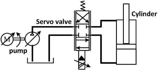
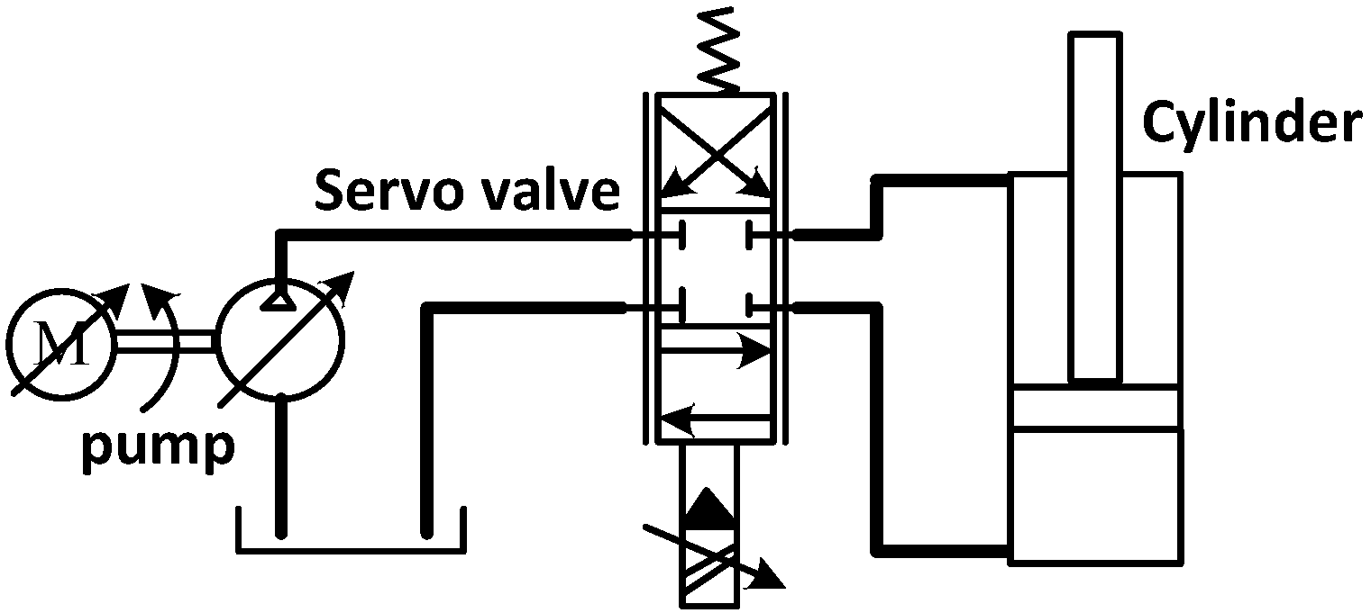
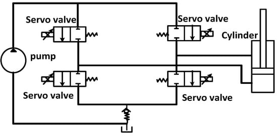
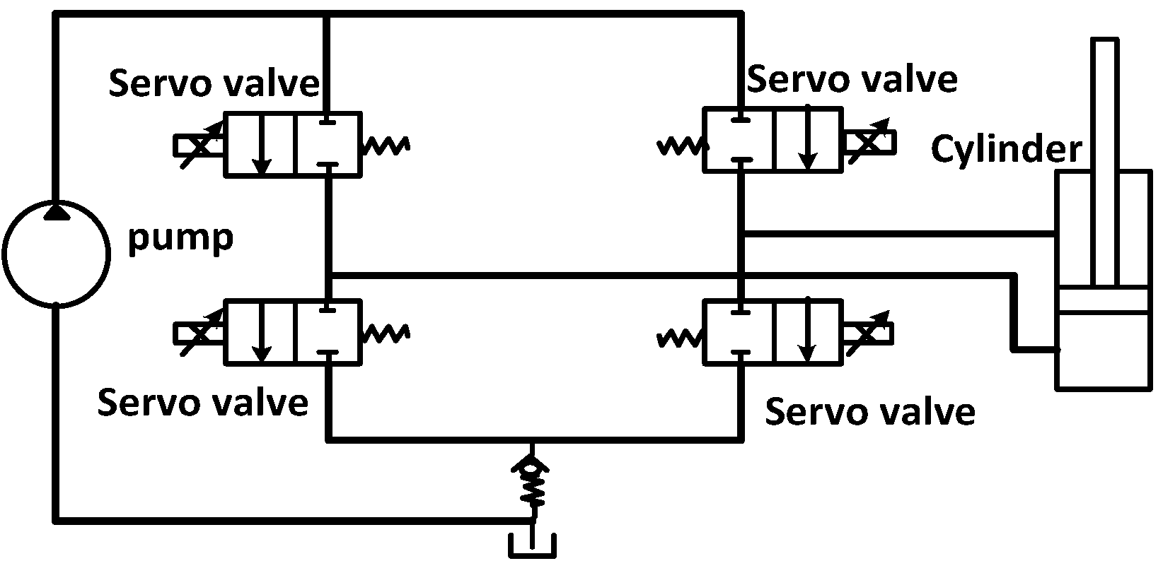
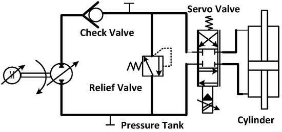
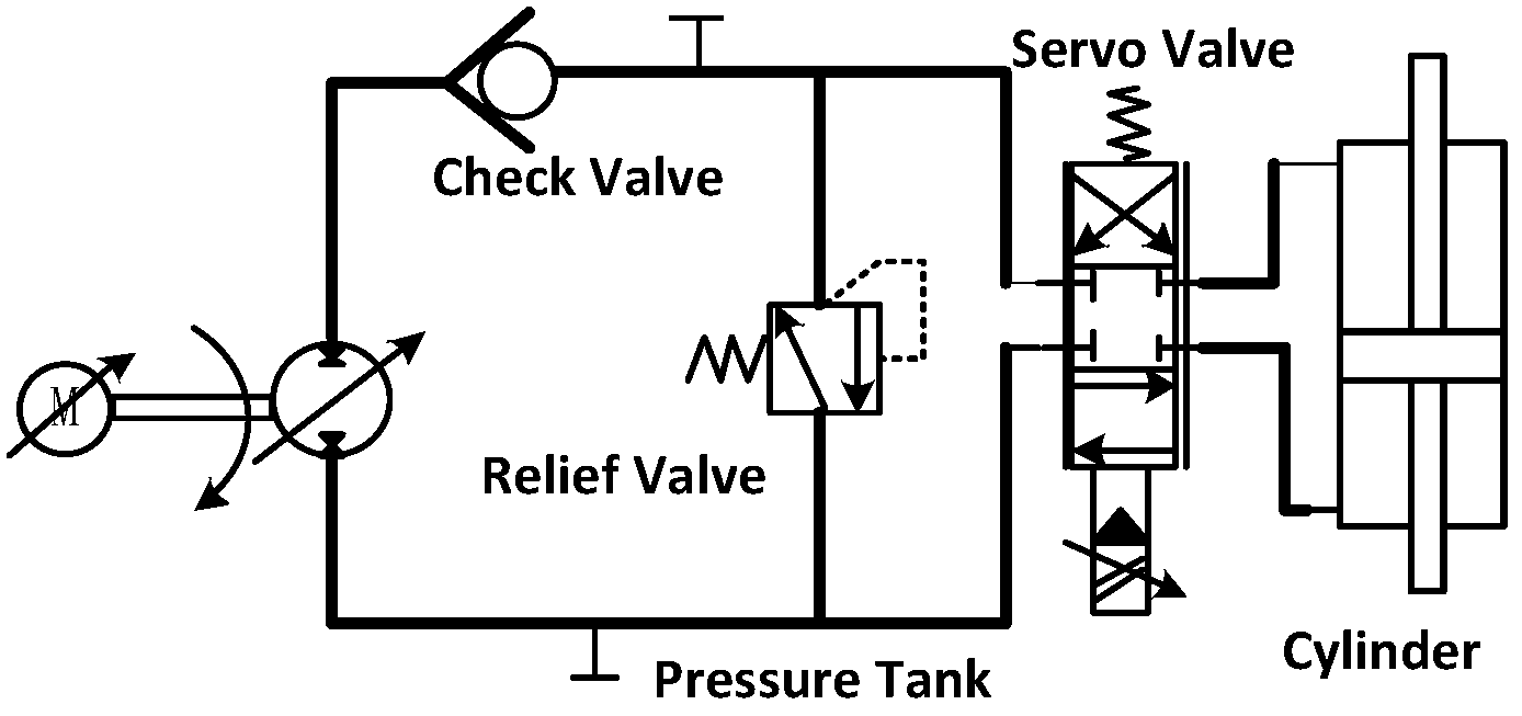
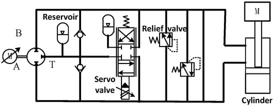
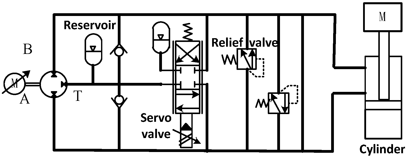
There have been many studies on the hydraulic circuit system throughout the world. Most of them improved the circuit structure, deigning new components with the combination of different control strategies; thus system accuracy, efficiency, and performance are improved [5]. In the light of the problem that the valve-controlled circuit has low efficiency, researchers tried to resolve this issue by using the valve control system of the variable-speed pump or independent metering valve technology. To resolve the energy saving and noise reduction issues in variable electro-hydraulic supply systems, Ali et al. [6] proposed the valve-controlled hydraulic cylinder circuit with variable speed pump. The proposed circuit structure is shown in Figure 1. Compared with the traditional valve control system, the relief valve is omitted, the relief loss is reduced, and the efficiency of the valve-controlled circuit is improved. Regarding the problems of energy waste and low efficiency in the valve-controlled circuit, Xu et al. [7] came up with an independent metering valve technology to replace the traditional valve-controlled circuit. The structure of the circuit is shown in Figure 2. This structure can realize the motion control and energy-saving control of the system; thereby, the efficiency of the valve control circuit is boosted.
Figure 1.
Valve-controlled circuit with variable speed pump.
Figure 2.
Structure of independent metering valve (IMV).
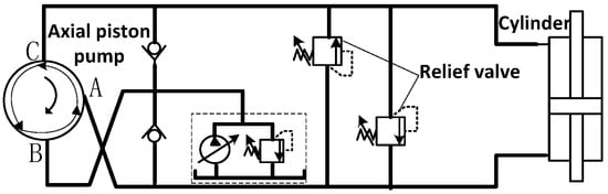
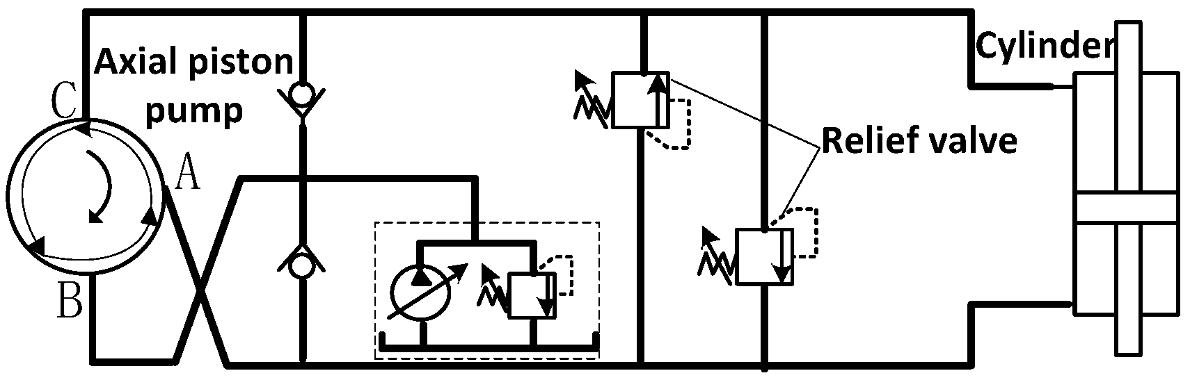
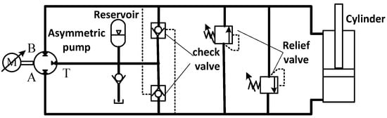
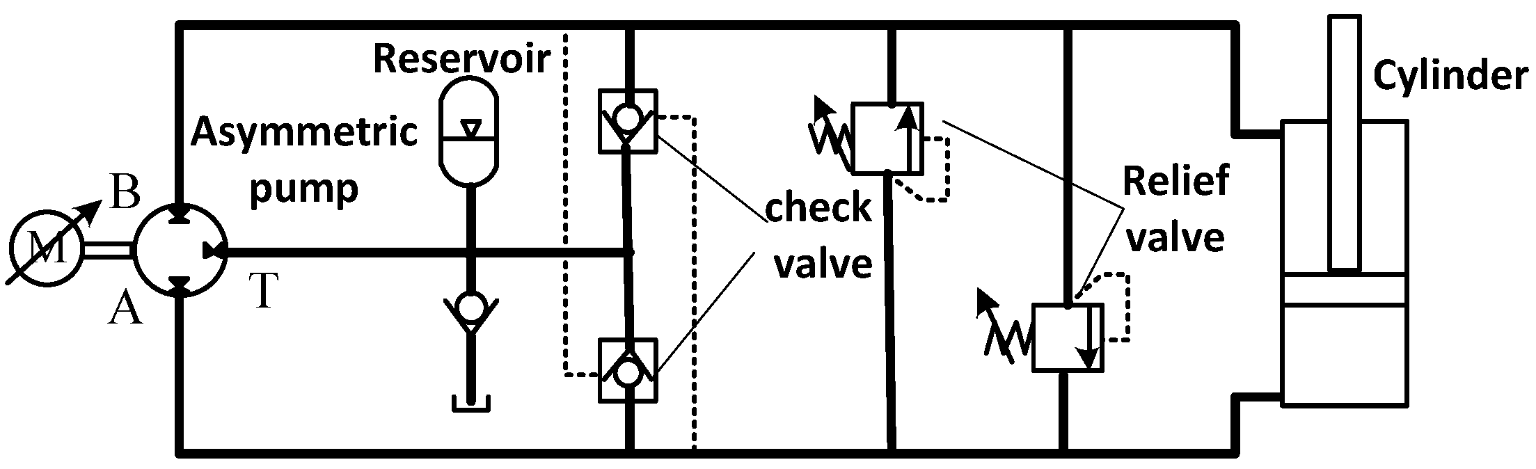
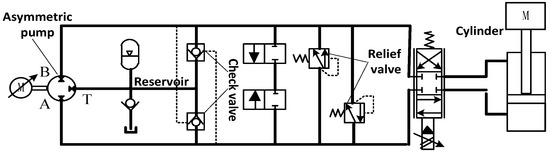
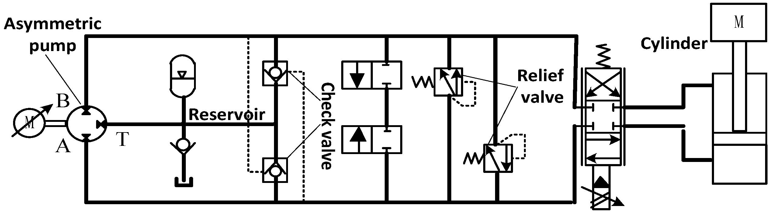
For the low performance of the pump control circuit, researchers developed the axial piston pump and variable speed pump system to improve the performance of the pump control circuit [8,9]. Owing to the problem of flow unbalance caused by the differential of the cylinders in the hydraulic circuit, Huang et al. [10] proposed a hydraulic circuit of a parallel three-port window axial piston pump to control the asymmetric cylinders. Figure 3 shows a scheme of transforming the oil suction window of the existing axial piston pump into two series windows, allowing the direct control of the differential cylinder by changing the displacement or speed of the pump. The area difference of the differential cylinder is compensated by the relief valve. This method can simplify the circuit structure and improve the performance of the pump control circuit. According to the requirement of high performance and high efficiency of the hydraulic injection molding machine, Quan et al. [11] proposed a pump-controlled hydraulic cylinder circuit with a variable speed pump. As shown in Figure 4, the two hydraulic operated check valves in the circuit are used to compensate the asymmetric flow of the asymmetric cylinder. The asymmetric cylinder system is driven by a variable speed motor. Therefore, it improves the performance of the pump control system. However, in the above literature, it was found that the structure of the single valve control circuit has throttling loss, which reduces the energy utilization rate. The proposed structure of the single pump control loop has the inherent shortcomings of insufficient dynamic response and poor positioning accuracy under heavy load.
Figure 3.
Asymmetric flow distribution mode and circuit principle to control differential cylinder.
Figure 4.
Pump-controlled circuit of variable speed pump.
Aiming to solve the problems of low efficiency of traditional valve control circuits and low performance of traditional pump control circuits, scholars adopted compound circuits, such as a series circuit of pump-valve and a parallel circuit of pump-valve. The pump-valve compound circuits reported in [12,13,14] have attempted to integrate the advantages of valve-controlled and pump-controlled circuits, but there are obvious limitations in topology design and functional synergy. Ketelsen et al. [12] proposed a series pump-valve compound circuit shown in Figure 5 for single-rod cylinders to improve energy efficiency and dynamic performance, yet its series structure leads to the mutual restriction of pump and valve flow, making it impossible to realize independent regulation of large-flow coarse control and small-flow fine control. Chen et al. [13] designed a series pump-valve electro-hydraulic actuation system for missiles in Figure 6, which achieves flow adjustment by coupling the pump and valve, but the series topology still has the defect of high throttling loss in the valve-controlled stage and fails to solve the problem of single-chamber preloading of hydraulic cylinders in the pump-controlled mode. Do et al. [14] put forward a parallel pump-valve electro-hydraulic actuator circuit based on an energy regulator shown in Figure 7, which realizes the joint drive of pump and valve, but its parallel structure only simply superposes the two circuits without rational matching of the oil supply pressure and pressure setting of the safety valves, resulting in serious pump-valve coupling interference and poor stability of system operation. While compound pump-valve circuits have been proposed to integrate the advantages of both configurations, existing series designs struggle to balance dynamic responsiveness and energy efficiency, while parallel designs lack optimized coordination mechanisms, leading to significant pump-valve coupling interference and unstable switching between control modes.
Figure 5.
Hydraulic circuit for a single rod cylinder.
Figure 6.
New missile electro-hydraulic actuation circuit.
Figure 7.
Electro-hydraulic actuator circuit based on energy regulator.
Despite numerous efforts to optimize hydraulic circuit control strategies, existing approaches still suffer from critical limitations that impede the simultaneous achievement of high dynamic performance and energy efficiency in demanding applications. For valve-controlled circuits, although advanced control methods such as proportional–integral–derivative (PID) control [15,16], neural network-fuzzy intelligent control [17,18], and adaptive back-stepping control [19,20] have been adopted to mitigate inefficiency, they primarily focus on algorithmic fine-tuning rather than addressing the inherent throttling loss of valve-based systems, resulting in limited energy-saving gains. For pump-controlled circuits, strategies including singular perturbation theory [21,22], adaptive sliding mode back-stepping control [23,24], robust control methods (LQR) [25], and model predictive control (MPC) [26,27] aim to enhance dynamic responsiveness, but they fail to resolve the core issue of single-chamber preloading in hydraulic cylinders, which leads to low natural frequency, insufficient load stiffness, and compromised dynamic performance. In recent years, intelligent control strategies represented by fuzzy control and adaptive control have been continuously innovated and applied in the field of fluid power and power electronic control, and a series of the latest research results have provided important reference for the control strategy design of pump-valve compound hydraulic circuits. For example, the research on harmonic and reactive power compensation of shunt active power filters based on adaptive fuzzy logic control (FLC) [28] has verified the excellent adaptability and anti-disturbance performance of adaptive fuzzy logic in handling the nonlinear and time-varying characteristics of parallel control systems, which provides a valuable reference for the coordination control of parallel pump-valve circuits with asymmetric dynamic response characteristics. Saad et al. [29] proposed a fuzzy logic controller for three-level shunt active power filters in harmonic and reactive power compensation and further optimized the fuzzy control algorithm for parallel multi-module control systems; its core idea of real-time fuzzy reasoning and parameter self-tuning for multi-branch flow power matching shows important refinement. However, current control strategies for compound pump-valve circuits lack optimized coordination mechanisms: existing designs either treat pump and valve control as independent modules without dynamic synergy or rely on simplistic switching logic that causes operational shocks and significant coupling interference between pump and valve flows. Additionally, most control frameworks are tailored to specific circuit topologies, lacking adaptability to multi-mode operation and failing to dynamically adjust control priorities across different working phases. This disconnects between control strategies and the integrated advantages of hybrid circuit designs, leaving a gap in achieving both high precision and energy efficiency for complex hydraulic systems.
On this basis, this study selected PID control as the core regulator combined with the self-designed adaptive three-stage control strategy, which takes into account the engineering applicability of traditional mature control algorithms and the adaptive optimization of intelligent control ideas. It is a reasonable control strategy design based on the comprehensive analysis of existing control methods and the latest research results.
In this paper, a new parallel circuit of valve-controlled open circuit and pump-controlled closed circuit is proposed, and the corresponding control method is demonstrated. The feasibility of the new circuit is verified by simulation. The corresponding contributions of this paper are as follows:
- (1)
- A novel parallel hydraulic circuit topology is proposed, integrating a valve-controlled open circuit and a pump-controlled closed circuit. This design synergizes the high dynamic performance of fast response, high precision, and load stiffness of valve-controlled circuits with the energy efficiency of pump-controlled circuits, addressing the inherent trade-off between performance and efficiency in traditional single-circuit systems.
- (2)
- An adaptive three-stage control strategy is developed for the new circuit: parallel pump-valve operation for accelerated dynamic response, pump-dominated control for energy-saving steady-speed operation, and valve-dominated control for high-precision positioning. Complemented by a smooth switching mechanism using first-order inertial link delay signals, this strategy eliminates operational shocks during pump-valve mode transitions and ensures stable system performance across different working phases.
2. Compound Hydraulic Principle
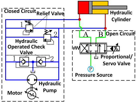
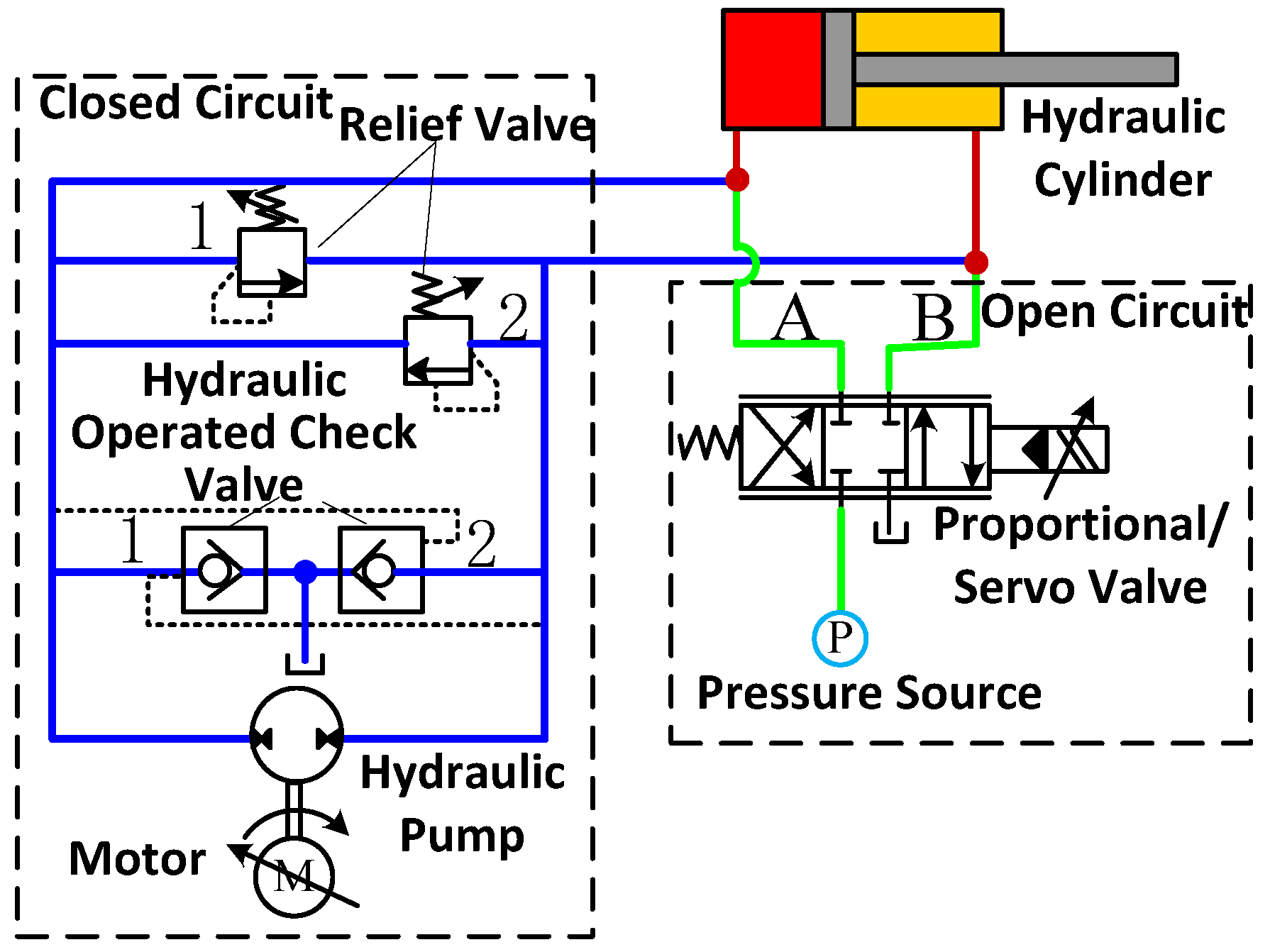
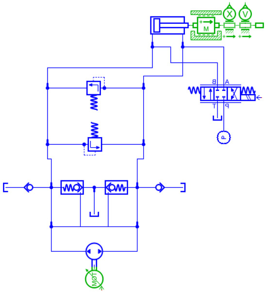
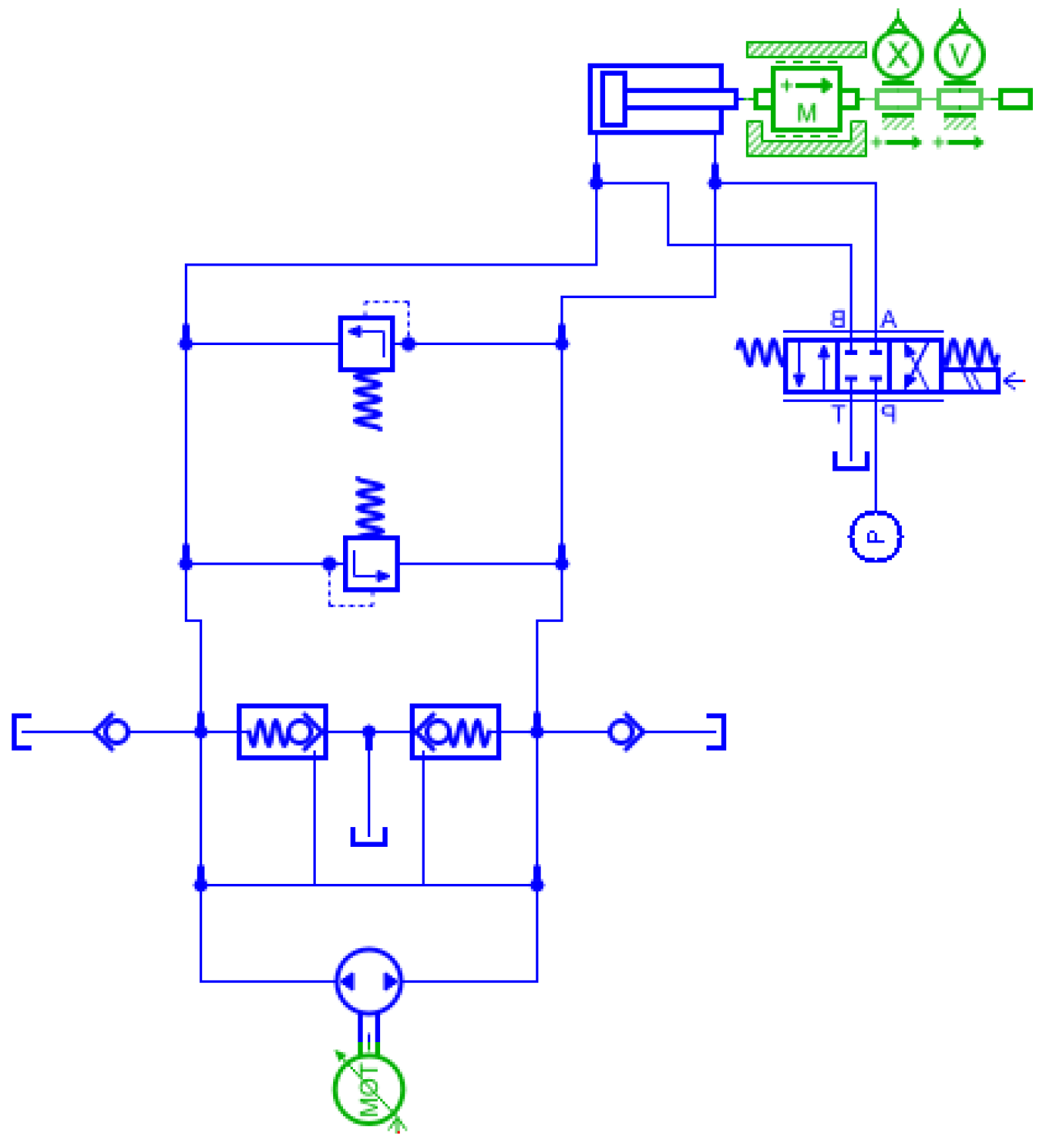
Combined with the high performance of the valve control circuit and the high efficiency characteristics of the pump control circuit, this paper proposes a compound parallel circuit of the valve control open circuit and the pump control closed circuit, shown in Figure 8.
Figure 8.
New circuit.
The proposed circuit consists of a valve-controlled open circuit and a pump-controlled closed circuit in parallel as shown in Figure 8. The pump control closed circuit is composed of a safety valve, a hydraulic operated check valve, a ration pump, and a motor, shown in Figure 8. In this circuit, two check valves, valve 1 and valve 2, are used to balance the difference in volume between two cavities of the asymmetric cylinder and to compensate the leakage flow. Two relief valves (relief valve 1 and relief valve 2) are also set by this circuit to prevent excessive pressure in the two chambers of the pump. The valve-controlled open circuit consists of a proportional/servo valve, an oil tank, and a pressure source, shown in Figure 8. The pressure of the circuit is supplied by the pressure source, which regulates the pressure at both ends of the valve.
In the process of hydraulic cylinder movement, the pump-controlled closed circuit plays a major role, while the valve-controlled open circuit plays a subsidiary role. Large flow is provided by the pump control circuit to complete coarse control. Small flow is given by the valve control circuit to achieve accuracy control. In Figure 8, symmetrical pumps are used in the closed circuit. To drive the hydraulic cylinder by the superposition of the pump-controlled flow and the valve-controlled flow, the oil supply pressure of the valve-controlled circuit should be greater than the setting pressure of the safety valve in the pump-controlled circuit. Otherwise, the pressure of the two chambers of the hydraulic cylinder may be greater than that of the oil source of the servo valve.
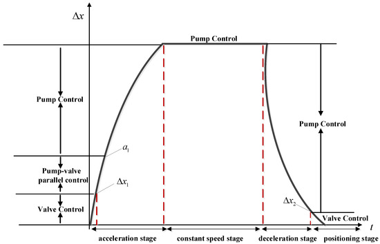
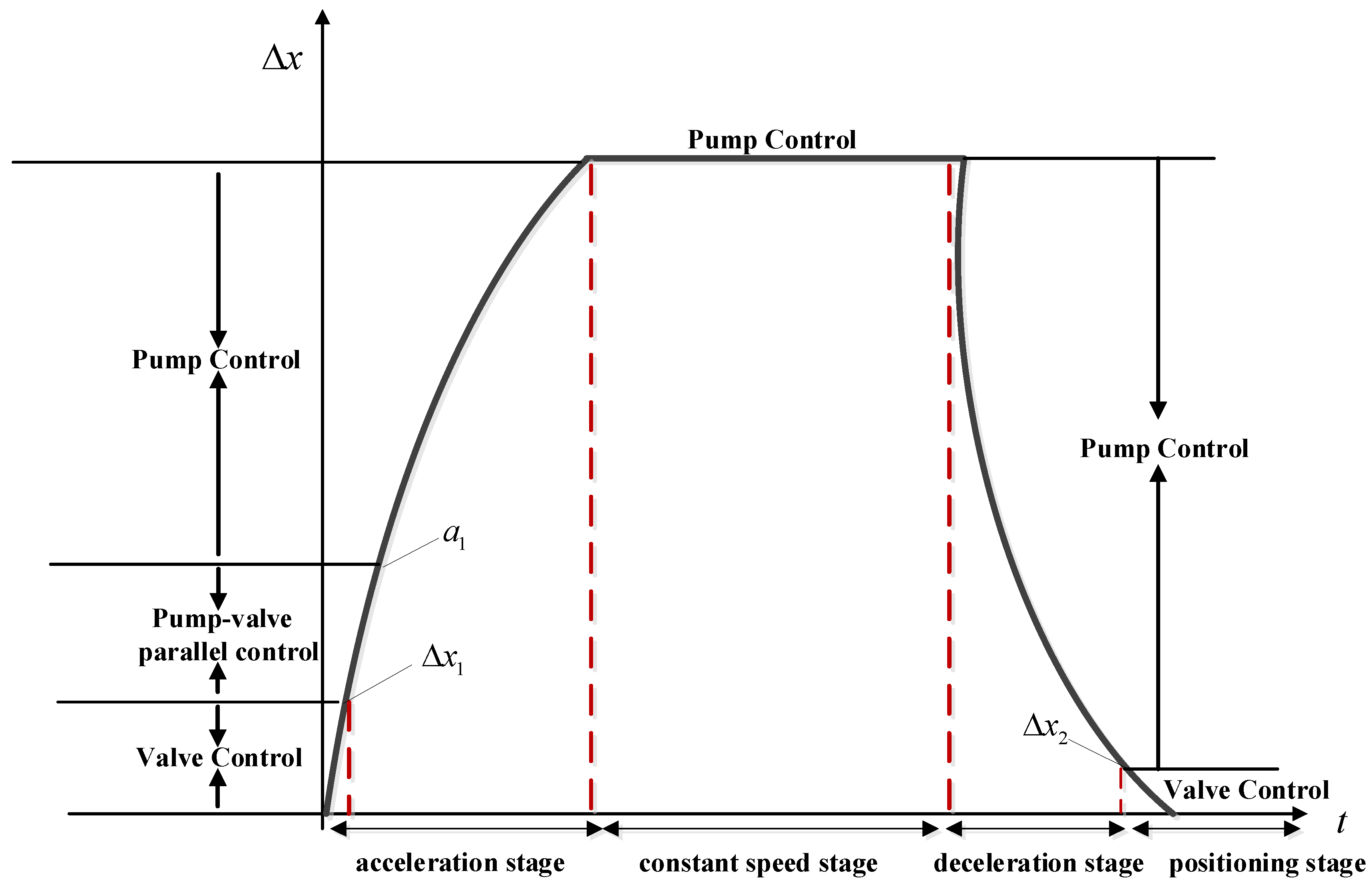
The proposed circuit can realize many flexible circuit control modes, such as pump-controlled closed circuits, valve-controlled open circuits, open-closed parallel circuits, etc. This circuit can acquire high efficiency and high performance by the following control method. The method is divided into three stages: (1) The parallel circuit of the pump and the valve is used in the dynamic operation process to speed up the dynamic process. (2) The pump control circuit is used in a constant speed operation section to achieve energy-saving operations. (3) The valve-controlled circuit is used in the positioning control section to achieve accurate positioning.
As a summary, high efficiency and high performance can be achieved by the new circuit system during the working process.
3. Adaptive Control Scheme
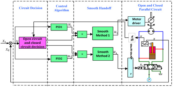
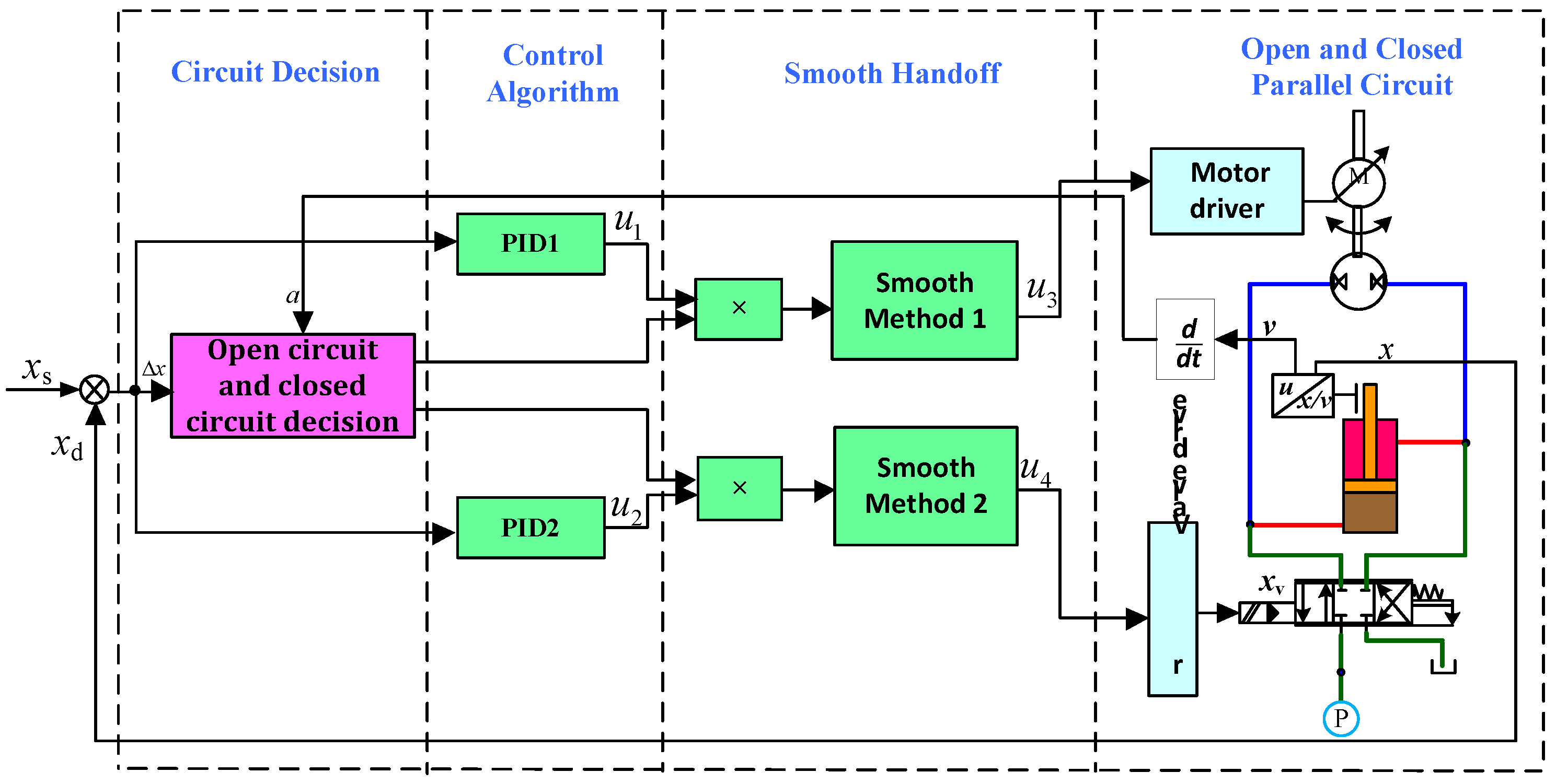
To make the control method of the new circuit become a reality, the following control scheme is proposed. As shown in Figure 9, the implementation of the control scheme requires the following three parts: (1) to make decisions on the new circuit according to the control method; (2) to adopt position feedback control according to the control method; (3) to achieve smooth switch of the new circuit according to the decision results. The PID position feedback control [15] is adopted in the new circuit. The PID position feedback calculation formulae are given by Equations (1) and (2):
where , are proportional coefficients of the position control.
Figure 9.
Control scheme block diagram.
The PID regulator forms a complementary synergy with the adaptive three-stage control strategy and smooth switching mechanism designed in this study—the adaptive circuit decision logic divides the system’s operation into different phases with distinct control demands, and the PID regulator’s parameters can be slightly adjusted for each phase to match the dynamic characteristics of pump-dominated or valve-dominated control, realizing a simple form of gain scheduling control without changing the core algorithm framework. This hybrid control mode combines the advantages of the PID regulator’s simplicity and the adaptive strategy’s flexibility, making the whole control system both easy to implement and capable of adapting to different operating phases of the system.
3.1. System Coordination Strategy
In the decision-making process of the new circuit, the major control is pump control, and valve control works in an auxiliary way. When the judge signal of the pump control circuit is 1 in the acceleration, constant speed, and deceleration stage, the pump control of the new circuit is decided. However, when the judging signal of the valve control circuit is 1 in the acceleration phase and the positioning process, the valve control of the new circuit is decided. The valve control circuit in the new circuit is judged by the acceleration and difference of the displacement target, and the pump control circuit is judged by the difference of the displacement target. The circuit decision is shown in Figure 10.
Figure 10.
Circuit decision.
is set as the minimum displacement difference that triggers the switch from pump-dominated control to valve-dominated control during the dynamic operation phase, taking the maximum allowable positioning error of the system under coarse control as the lower limit to ensure the timeliness of precision regulation; is defined as the critical displacement difference for high-precision positioning control, which is determined by the rated positioning accuracy of the servo valve and the static error of the hydraulic cylinder, to guarantee the final positioning precision of the system. The acceleration threshold is designed based on the maximum stable acceleration of the hydraulic cylinder driven by the pump-controlled closed circuit and the dynamic response limit of the quantitative pump, taking the minimum acceleration of the hydraulic cylinder during the dynamic start-up and acceleration phase as the judgment criterion, which can accurately identify the dynamic operation stage of the system and trigger the pump-valve parallel drive mode in a timely manner. The specific basis is given by Equations (3)–(5).
The acceleration threshold is designed based on the maximum stable output acceleration of the pump-controlled closed circuit and the minimum effective acceleration required for the dynamic start-up of the heavy-load hydraulic cylinder, with its quantitative design Formula (3) given as follows:
where is the rated output pressure of the quantitative pump, is the effective acting area of the hydraulic cylinder rodless cavity, is the viscous friction force of the hydraulic cylinder, is the minimum steady load of the system, is the equivalent load mass, and is the minimum acceleration that characterizes the start of the hydraulic cylinder’s dynamic operation phase, determined by the system’s dynamic response performance requirements.
The displacement difference threshold for dynamic operation phase switching is designed based on the maximum allowable positioning error of the pump-dominated coarse control and the response delay of the valve-controlled circuit, with the design Formula below (6):
where is the maximum static positioning error of the pump-controlled closed circuit under steady operation, is the rated operating speed of the hydraulic cylinder, and is the electro-hydraulic response delay of the servo/proportional valve, which ensures that the valve-controlled circuit is triggered in advance to compensate for its response delay and to avoid positioning error accumulation.
The displacement difference threshold for high-precision positioning is determined by the rated positioning accuracy of the valve-controlled circuit and the static error of the hydraulic cylinder system, with the Formula (6):
where is the rated positioning control error of the servo/proportional valve, and is the static leakage and friction-induced positioning error of the hydraulic cylinder, which is the critical threshold for switching to valve-dominated control to ensure the final positioning precision of the system. The circuit decision is given by Equations (6)–(8):
When is determined by the minimum acceleration of the hydraulic cylinder during dynamic operation process.
When is determined by the minimum displacement difference of the hydraulic cylinder during dynamic operation process.
When is determined by the maximum displacement difference of the hydraulic cylinder during positioning process.
3.2. Smooth Handoff
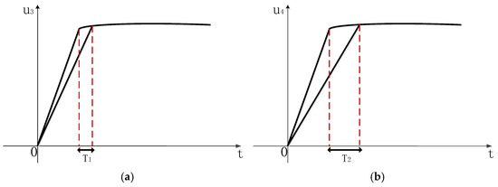
Smooth switching of the new circuit mainly includes smooth method 1 and smooth method 2. In the stage of acceleration, constant speed, and deceleration, position feedback and delay control are carried out by the pump control circuit to achieve a smooth switching from pump-controlled to valve-controlled of the new circuit. In the acceleration phase and positioning process, the position feedback and delay control are applied to the valve-controlled circuit to achieve smooth switching from valve-controlled to pump-controlled of the new circuit. The smooth method of the circuit is shown in Figure 11.
Figure 11.
Smooth method (a,b).
Smooth method 1 is shown in Figure 11a: when the circuit switches smoothly from the pump control circuit to the valve control circuit, a delay signal occurs that the first-order inertial link is added to the pump signal because of the fast response of the valve control. Smooth method 2 is shown in Figure 11b: when the valve control circuit is smoothly switched to the pump control circuit, because the pump control response is slow, a delay signal occurs that the first-order inertial link is added to the valve signal. The delay control calculation formulae [19] are given by Equation (9):
where T1, T2 are the time parameters of the one order inertial link. According to the response time of the valve, T1 is determined. According to the response time of the pump, T2 is determined.
Specifically, T1 is tailored for the fast electro-hydraulic response characteristic of the servo valve. When switching from pump control to valve control, T1 is set to be slightly larger than the servo valve’s response time to make the pump control signal decay smoothly through the first-order inertial link at a rate matching the rising rate of the valve control signal, which compensates for the slow response decay of the pump-controlled circuit caused by the motor and pump mechanical inertia and avoids system flow overshoot or operational shocks induced by the valve’s rapid response.
In contrast, T2 is designed to match the slow mechanical dynamic response characteristic of the pump-controlled closed circuit. The total mechanical response time of the quantitative pump and motor drive system is approximately 0.3~0.4 s due to large rotational inertia and hydraulic volume inertia. When switching from valve control to pump control, T2 is calibrated to the central value of the pump’s mechanical response time range, which enables the valve control signal to attenuate at a rate that adapts to the slow rising rate of the pump control signal, eliminating the flow gap and pressure fluctuation caused by the pump’s slow start-up and ensuring the smooth superposition of pump and valve flow during the mode conversion process. In summary, the values of T1 and T2 are directly derived from the intrinsic dynamic response parameters of the valve and pump components, and their rational calibration is the core to realize the coordinated matching of the asymmetric response characteristics between the valve and pump, thus ensuring shock-free and smooth switching of the pump-valve compound circuit.
4. Simulation Result
4.1. Simulation Modeling
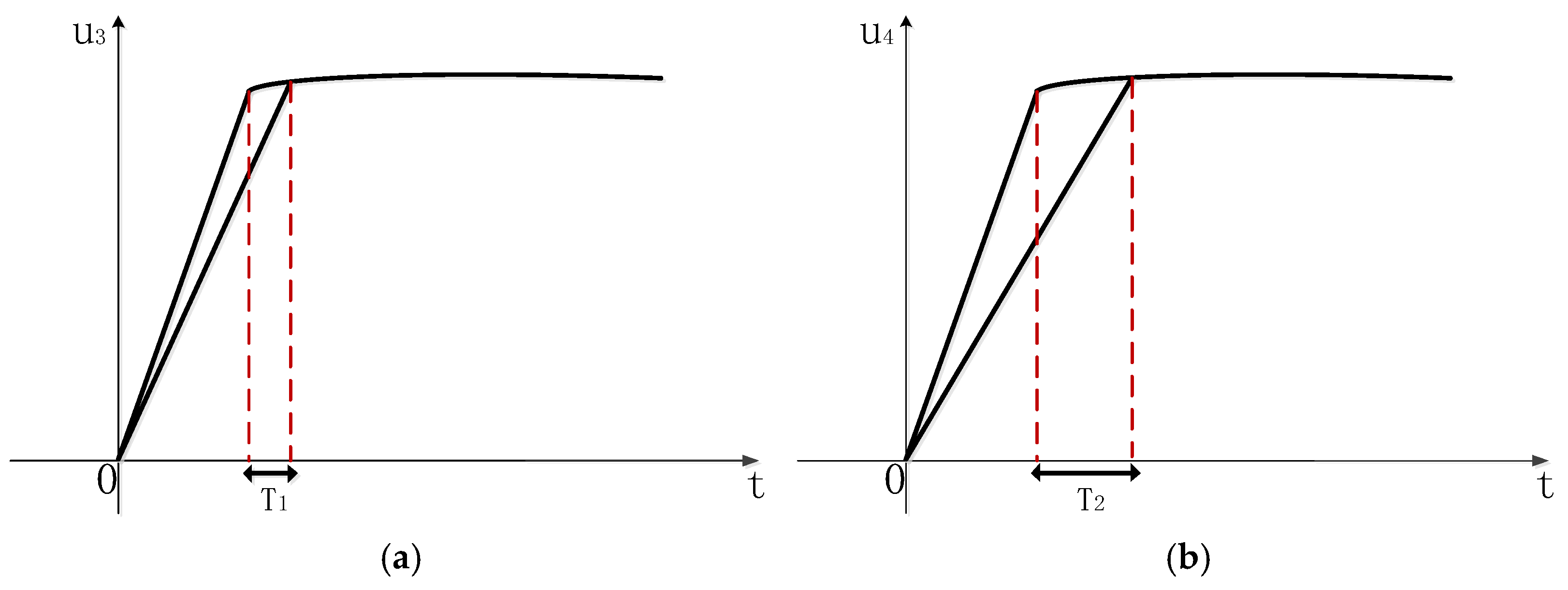
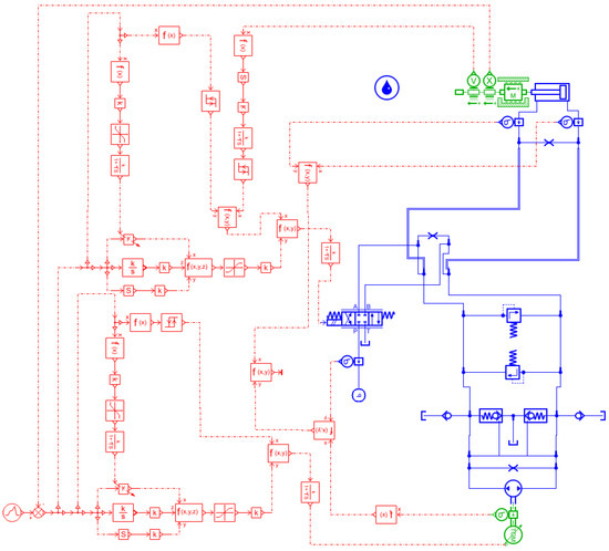
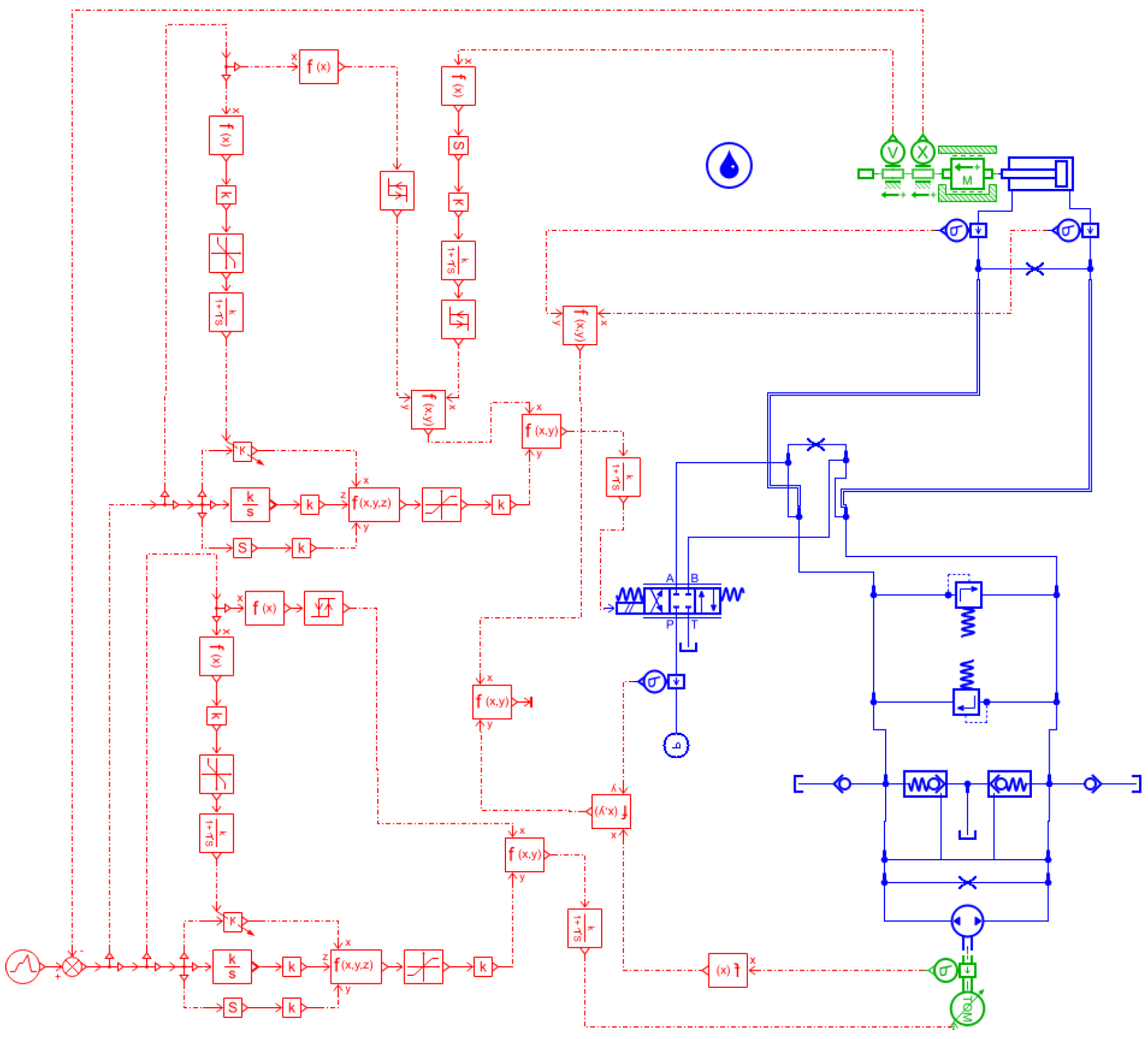
To verify the effectiveness of the new circuit control strategy proposed above, AMESim is used for simulation. The simulation built the model of the parallel system of pump and valve in the new circuit as shown in Figure 12. Then, the control strategy of the circuit shown in Figure 13 was implemented. To compare the dynamic characteristics and system efficiency of the new circuit system, the model of the direct pump control system and the traditional valve control system is first built, and then the rising time, system efficiency, and response speed of the new circuit system and these two systems are compared.
Figure 12.
New circuit model.
Figure 13.
Control strategy.
The setting-up parameters are shown in Table 1. There is a linear relationship between the valve orifice area (percentage) and the valve core displacement (percentage): from the pressure characteristic curve of the servo valve, the volume ratio of the pump is 0.8. The natural frequency and damping ratio of the valve are 80 Hz and 0.6 respectively.
Table 1.
Main parameters in AMESim model.
4.2. Double Circuit Operation Analysis
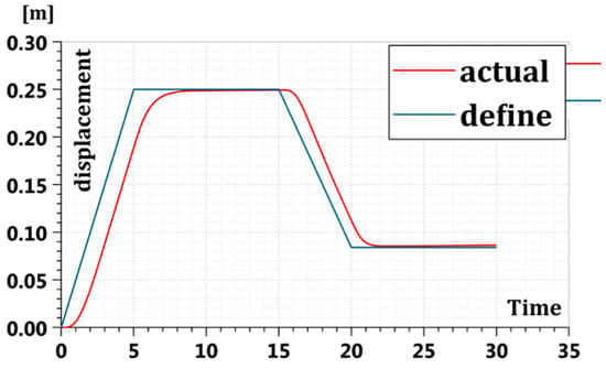
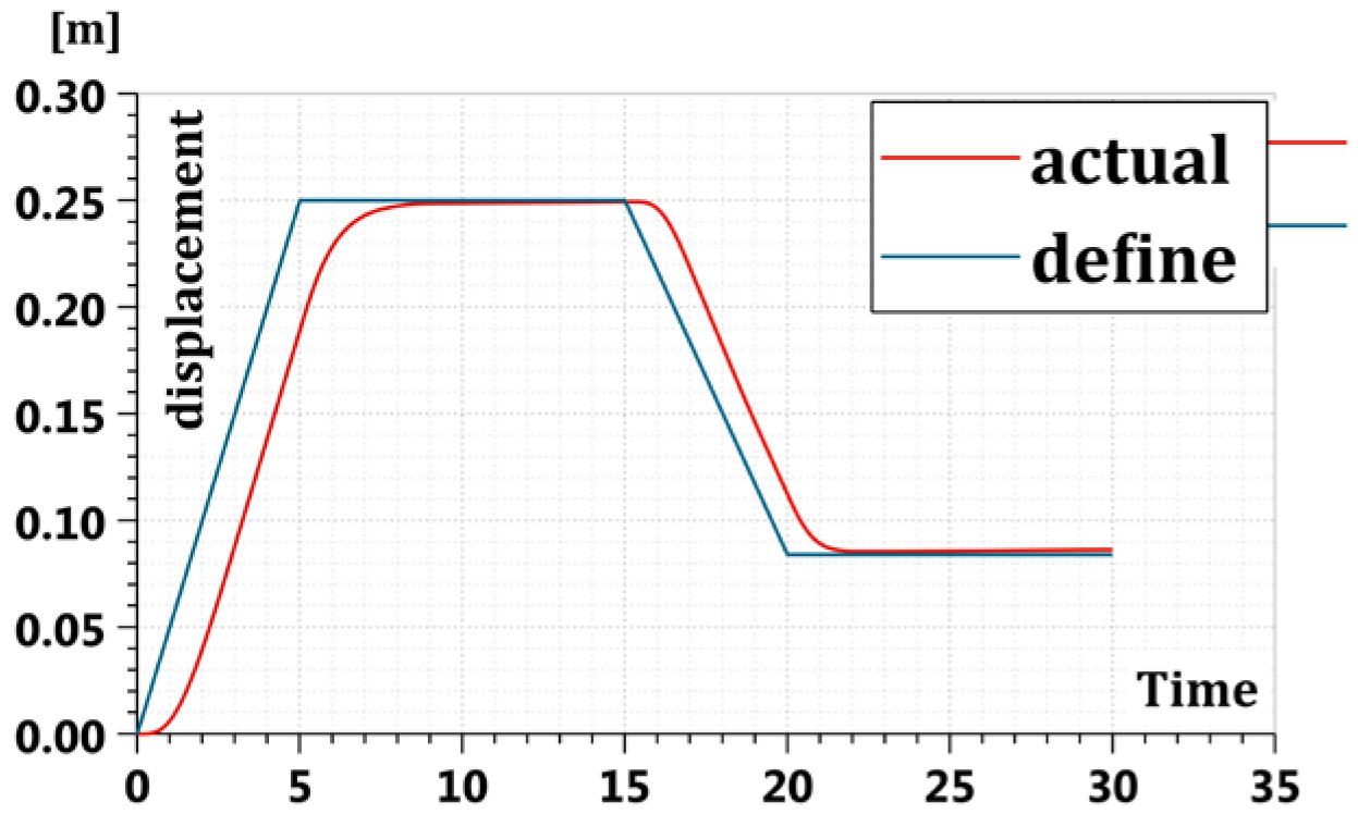
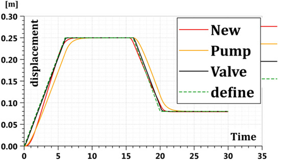
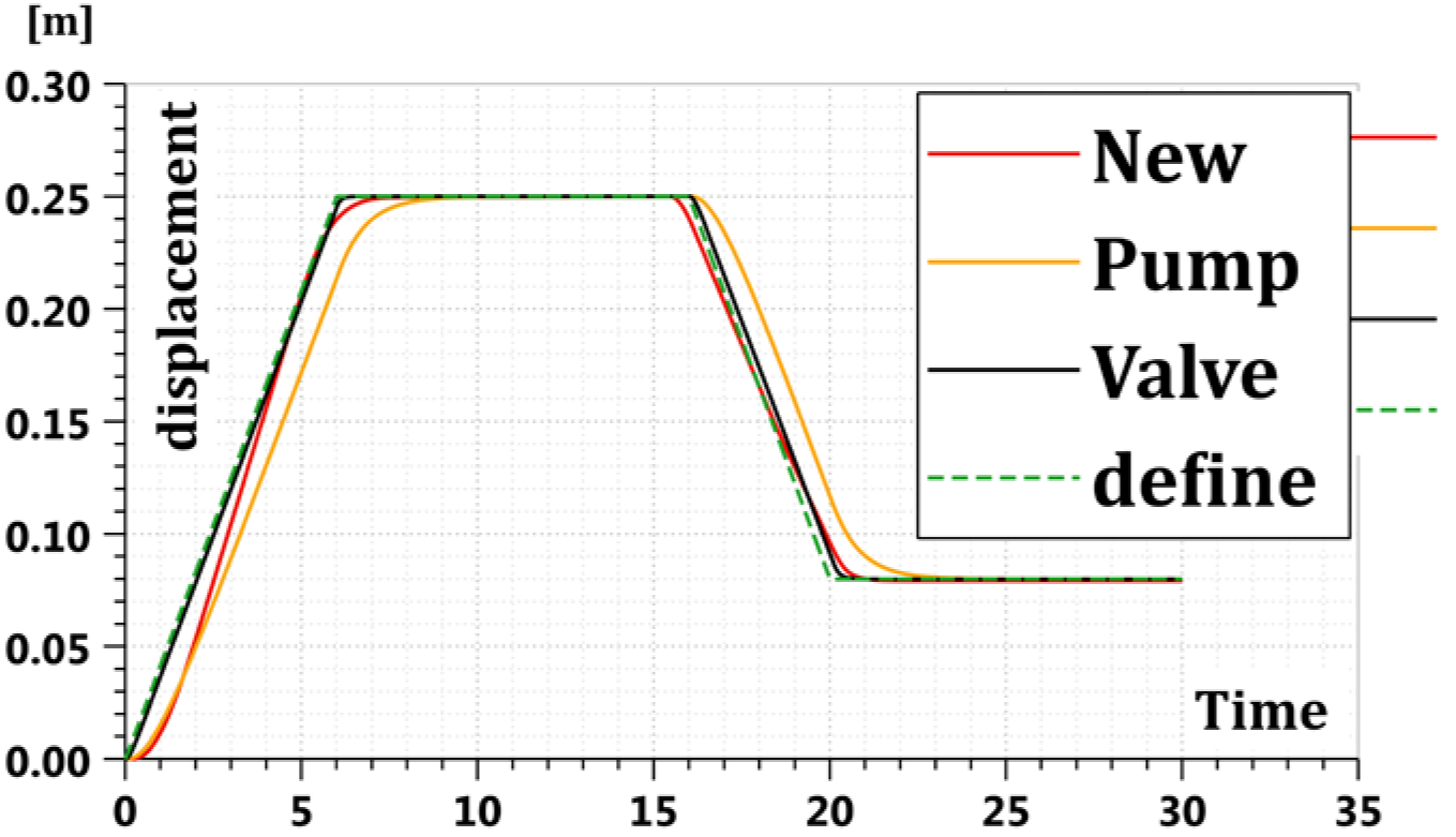
AMESim simulation technology was used to verify the operation of the new circuit. The given displacement is set as the curve rising 0.25 m and decreasing 0.08 m as shown in Figure 14. Figure 14 shows the position tracking curve of the new circuit. Figure 15 shows the flow curve of the overflow valve of the new circuit, and Figure 16 indicates the flow curve of the hydraulic operated check valve of the new circuit.
Figure 14.
Operation curve of the circuit.
Figure 15.
Flow curve of overflow valve.
Figure 16.
Flow curve of hydraulic operated check valve.
Through simulation, the curve in Figure 14 shows that the position tracking performance of the new circuit is good. The curve in Figure 15 verifies that the overflow valves 1 and 2 keep the outlet pressure of the pump constant. It can be seen that the hydraulic operated check valve 1 and 2 can balance the volume difference between the two cavities of the asymmetric cylinder and ensure constant oil in the two cavities of the pump in Figure 16. Thus, the new circuit is verified as running well.
4.3. Double Circuit Smooth Handoff Analysis
By using the AMESim simulation technology, the smooth handoff of the control scheme proposed by the new circuit is simulated and verified.
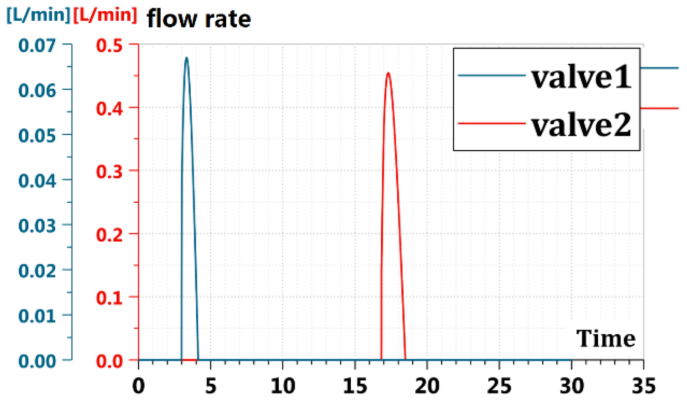
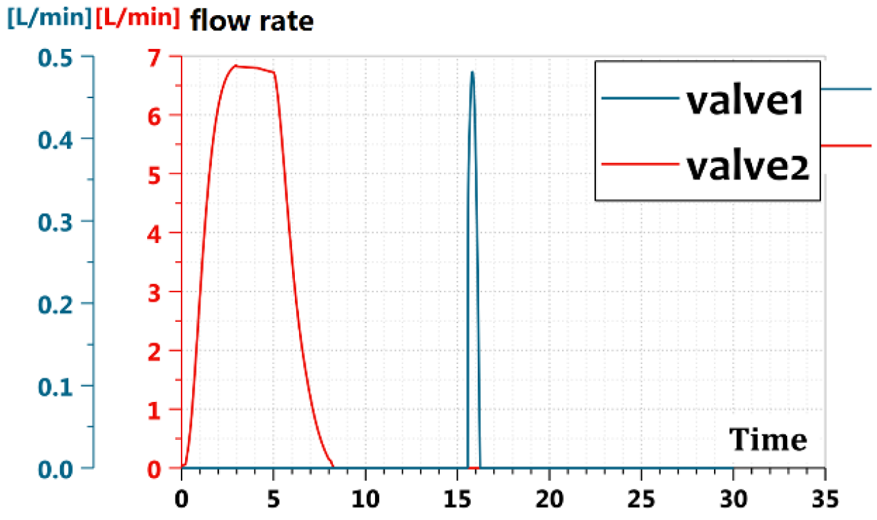
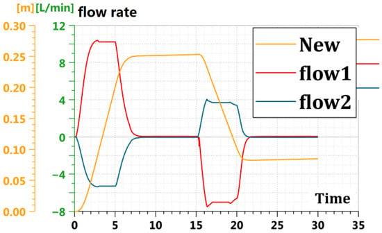
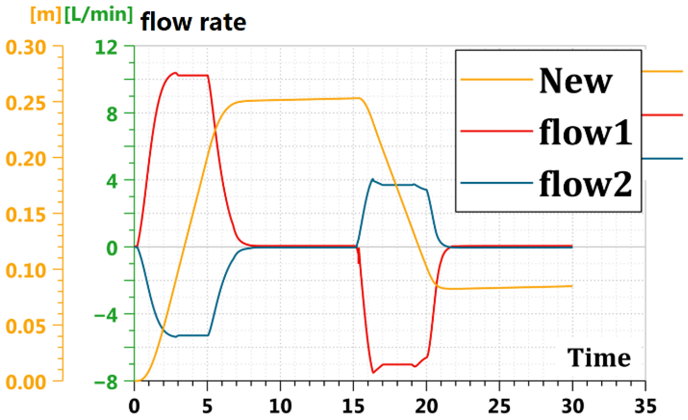
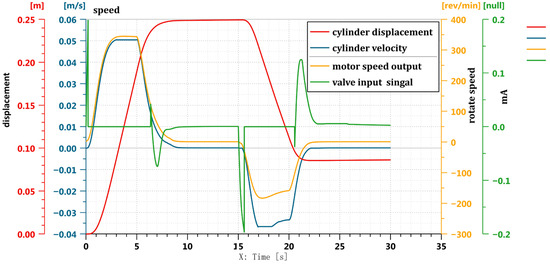
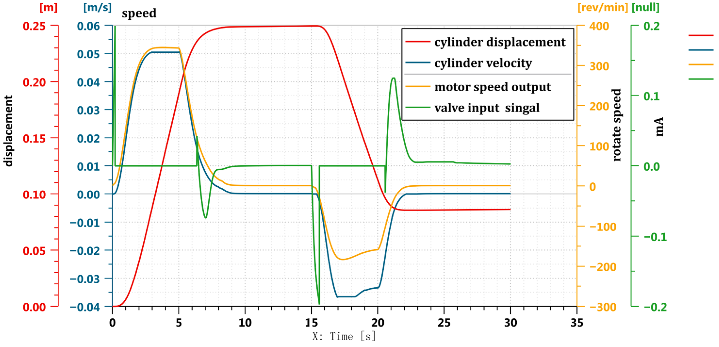
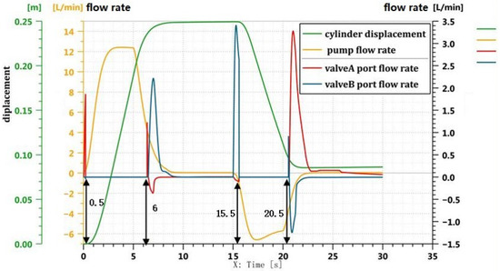
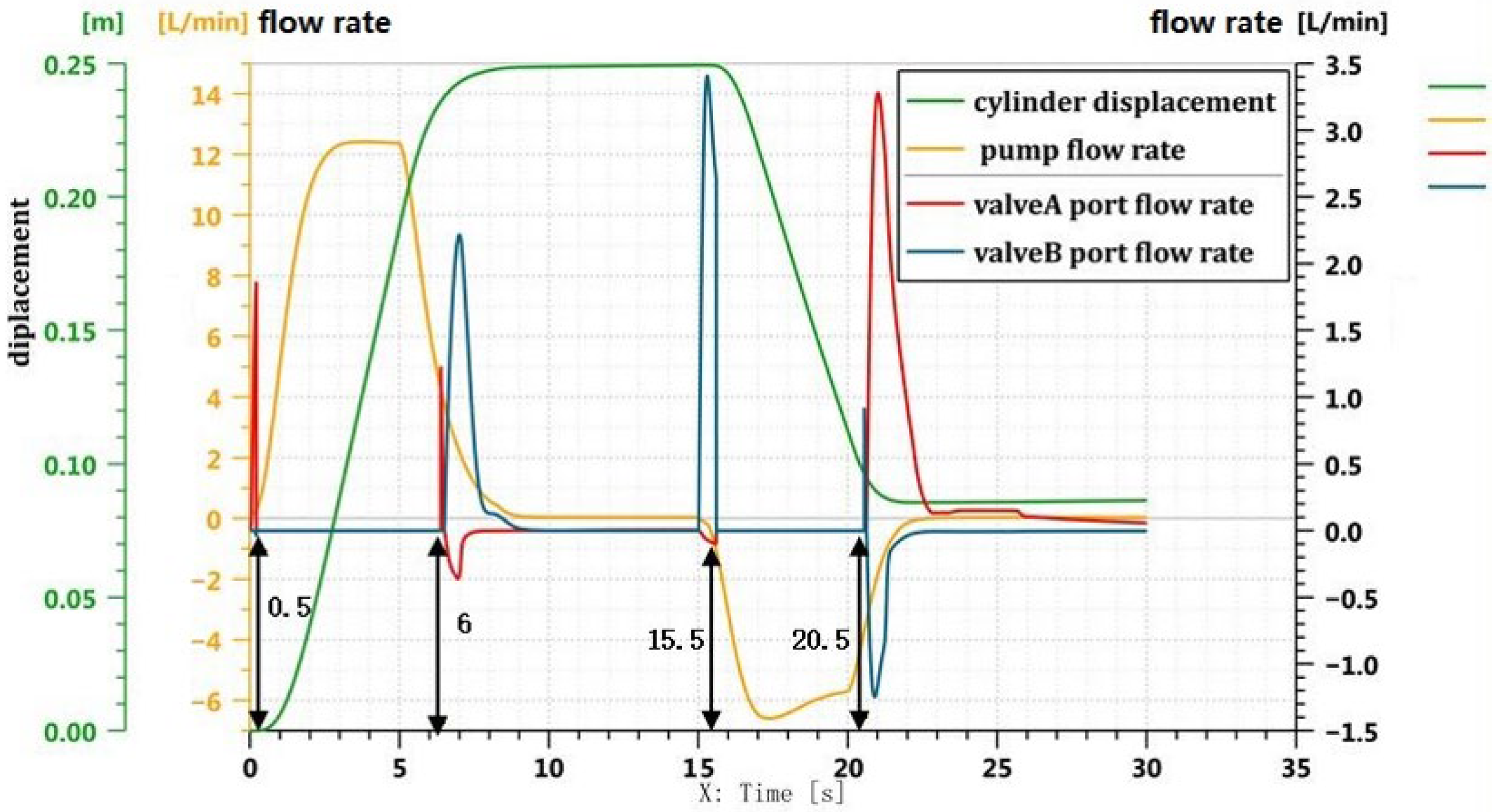
Figure 17 shows the curve of the system flow rate in the new circuit. Figure 18 shows the control strategy curve proposed for the new circuit. Figure 19 shows the smooth switching curve of the new circuit. (This valve is the servo valve.)
Figure 17.
Flow curve of system in new circuit.
Figure 18.
Circuit control strategy curve.
Figure 19.
Smooth switching curve of the new circuit.
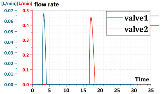
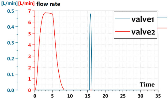
Through the simulation, it was found that the implementation control strategy of the new circuit (shown in Figure 18) is correct for the flow rate curve of the pump and valve in Figure 19. Figure 19 shows the flow switching from pump control to valve control in 0.5 or 15.5 s and the flow switching from valve control to pump control in 6 or 20.5 s. It verifies that the circuit handoff is smooth and that there is no impact between the pump-valve compound circuit in the process of circuit switching in Figure 19. According to the curve shown in Figure 17, it can also be seen that the flow rate curve of the system in the new circuit is smooth, which verifies that the circuit handoff is smooth.
4.4. Double Circuit Pressure Analysis
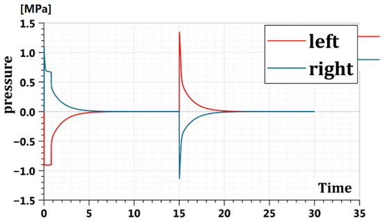
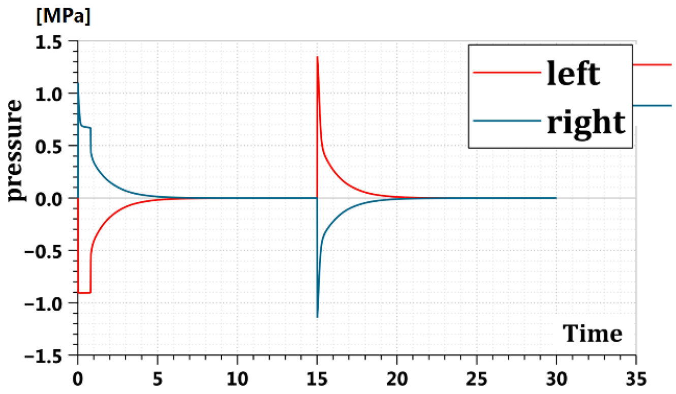
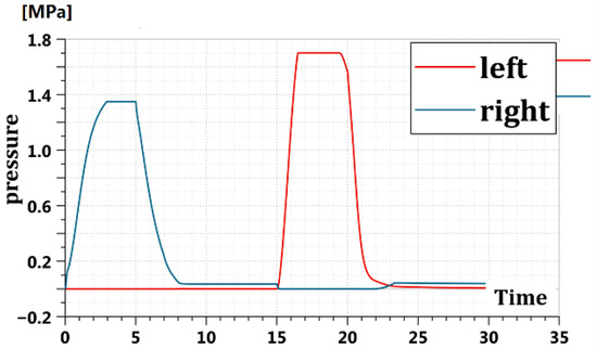
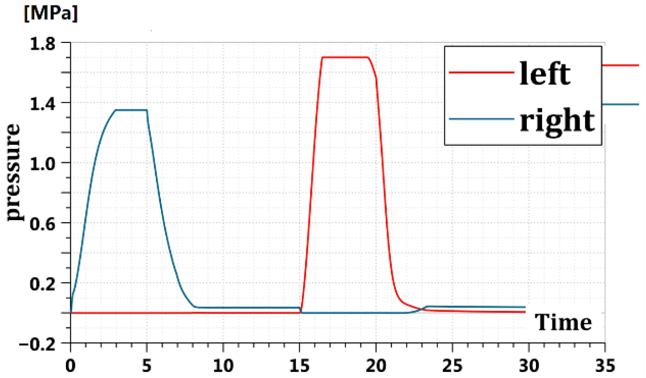
By using AMESim simulation technology, the new circuit pressure was simulated and verified. Figure 20 shows the pressure curve of the pump’s two cavities in the direct pump control circuit. Figure 21 shows the pressure curves of the two chambers of the pump in the new circuit.
Figure 20.
Pressure curve controlled by single pump.
Figure 21.
Pressure curve of the new circuit.
From the simulation, the comparison of the curves shown in Figure 20 and Figure 21 verify that the pressure of both chambers of the pump in the new circuit is preloaded. Thus, the hydraulic cylinder of the two cavities in a preloaded state can be verified. The new circuit solves the problem that only one chamber of the asymmetric hydraulic cylinder is preloaded in the direct pump control working process, resulting in the lower natural frequency of the system and affecting the dynamic characteristics of the system. Thus, the natural frequency and load rigidity of the circuit system are improved.
Based on the simulation parameters and structural design of the paper, the specific increase of the natural frequency can be calculated by the following steps. Using the hydraulic cylinder parameters (cylinder diameter, rod diameter, stroke), the oil elastic bulk modulus, the single chamber preload pressure and according to the classical formula of hydraulic stiffness , the hydraulic stiffness of the traditional single pump circuit is , and the equivalent mass is ; then, the corresponding natural frequency is calculated to be . Next, the total hydraulic stiffness of the pump-valve compound circuit is calculated by combining the pre-pressure of the double chamber and the throttling stiffness of the valve control circuit, including the flow coefficient and opening degree of the servo valve; the equivalent mass is , and then the corresponding natural frequency is calculated to be . Finally, according to the calculated and , the increase of the natural frequency of the system a is calculated in Equation (10) as follows (1,2):
The proposed pump-valve compound circuit increases the system’s inherent natural frequency by approximately 18.5% compared with the traditional single-pump circuit (rising from 22.3 Hz to 26.4 Hz) under the rated working condition, which clearly demonstrates the enhancement effect of the proposed topology on the system dynamic stiffness.
4.5. Double Circuit Performance Analysis
In the AMESim simulation model of this study, the servo valve is modeled based on the ideal electro-hydraulic conversion characteristic, where the input power is directly defined as the effective hydraulic power output by the servo valve after electro-hydraulic conversion excluding the power loss of the servo valve’s electrical control unit. The electrical signal input power of the servo valve is negligible compared with the hydraulic power of the system, so the direct participation of in the total input power calculation can simplify the efficiency analysis process without affecting the relative comparison of the efficiency of the three circuits of the proposed compound circuit, the direct pump-controlled circuit, and the traditional valve-controlled circuit. The system efficiency calculation Formulae (5) are given by Equation (11):
where is motor input power, is servo valve input power, is load output power, is cylinder output power.
For the transmission efficiency of the electric pump, the simulation model has incorporated the rated volumetric efficiency and mechanical efficiency of the quantitative pump into the motor-pump drive unit, and the motor input power in Equation (11) is the actual electrical power input to the motor after considering the pump’s transmission loss. This means the pump’s transmission efficiency has been implicitly reflected in the parameter setting of the simulation model and does not need to be additionally calculated in the efficiency formula. In terms of the power loss of auxiliary components such as safety valves and hydraulic operated check valves, the two types of valves in the proposed pump-valve compound circuit are in the normally closed or pressure-stabilized working state under the designed working conditions: the safety valve only works when the system pressure exceeds the set value, and the hydraulic operated check valve only compensates for the small flow of cavity volume difference and system leakage, so that their power loss is far less than the main power of the pump and valve circuits in the normal operation stage of the system. The neglect of such minor power loss in Equation (11) is a reasonable simplification for the overall efficiency analysis of the system, which can focus on the core power input and output characteristics of the main circuit and improve the clarity of the efficiency comparison between different circuits.
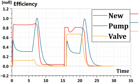
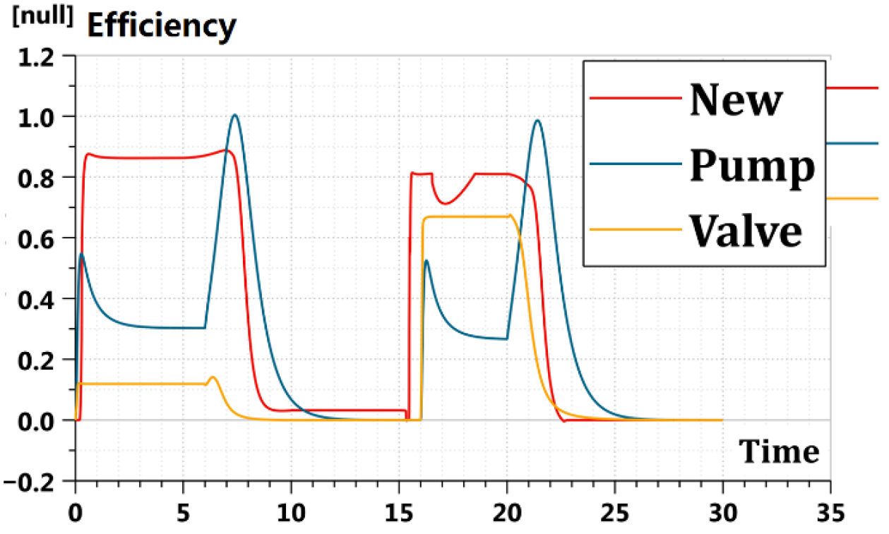
All three systems—the direct pump control system, traditional valve control system and the new circuit system—control the same hydraulic cylinder, and the control performance and efficiency of each system are obtained through AMESim simulation. Figure 22 and Figure 23 show the corresponding efficiency and control effect curves of the three circuits. Among them, the control strategy is adopted by the new circuit system in this paper, and PID control strategy is used by the direct pump control system and the traditional valve control system. The system efficiency of the three circuits is calculated according to Equation (6). (This valve is the servo valve.)
Figure 22.
Efficiency comparison curve.
Figure 23.
Rise time and response comparison curve.
According to the simulation results, it can be seen that the new circuit response and rise time are as fast as the traditional valve control circuit, and the new circuit efficiency is as high as the direct pump control circuit in Figure 22 and Figure 23. Thus, the compound strategy of the new circuit is verified as being correct, and the characteristics of high response, high precision, and high energy efficiency proposed by the new circuit are achieved.
In this paper, the new loop adopts a three-stage adaptive control strategy with the pump control as main and the valve control as auxiliary. In the rising stage of dynamic response, the pump-valve parallel working mode is adopted—the valve control loop provides fast small flow accurate adjustment, and the pump control loop provides large flow rough adjustment. The dynamic response characteristics of the system at this stage are mainly dominated by the valve control loop, and the efficiency characteristics of the pump control loop are mainly reflected in the constant speed operation stage, which is the pump-led energy-saving mode. Therefore, in the simulation analysis of the rise time and response speed, it is reasonable not to include the pump efficiency, because the performance of this stage is determined by the valve-controlled circuit, and the pump efficiency has no significant effect on the dynamic upward trend.
4.6. Double Circuit Coupling Analysis
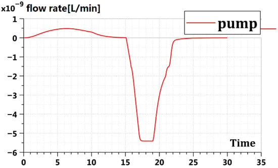
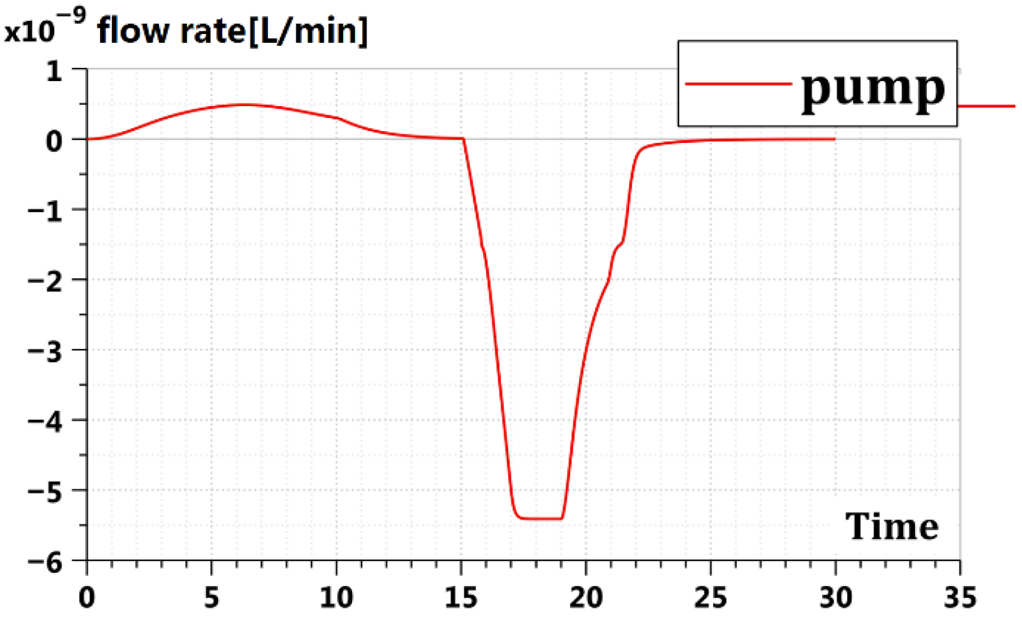
By using the AMESim simulation technology, the new circuit coupling was simulated and verified. Figure 24 shows the pump flow curve in circuit coupling. Figure 25 shows the valve flow curve in circuit coupling. (This valve is the servo valve.)
Figure 24.
Pump flow curve in circuit coupling.
Figure 25.
Valve flow curve in circuit coupling.
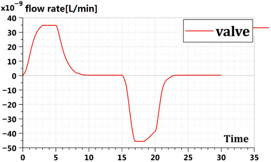
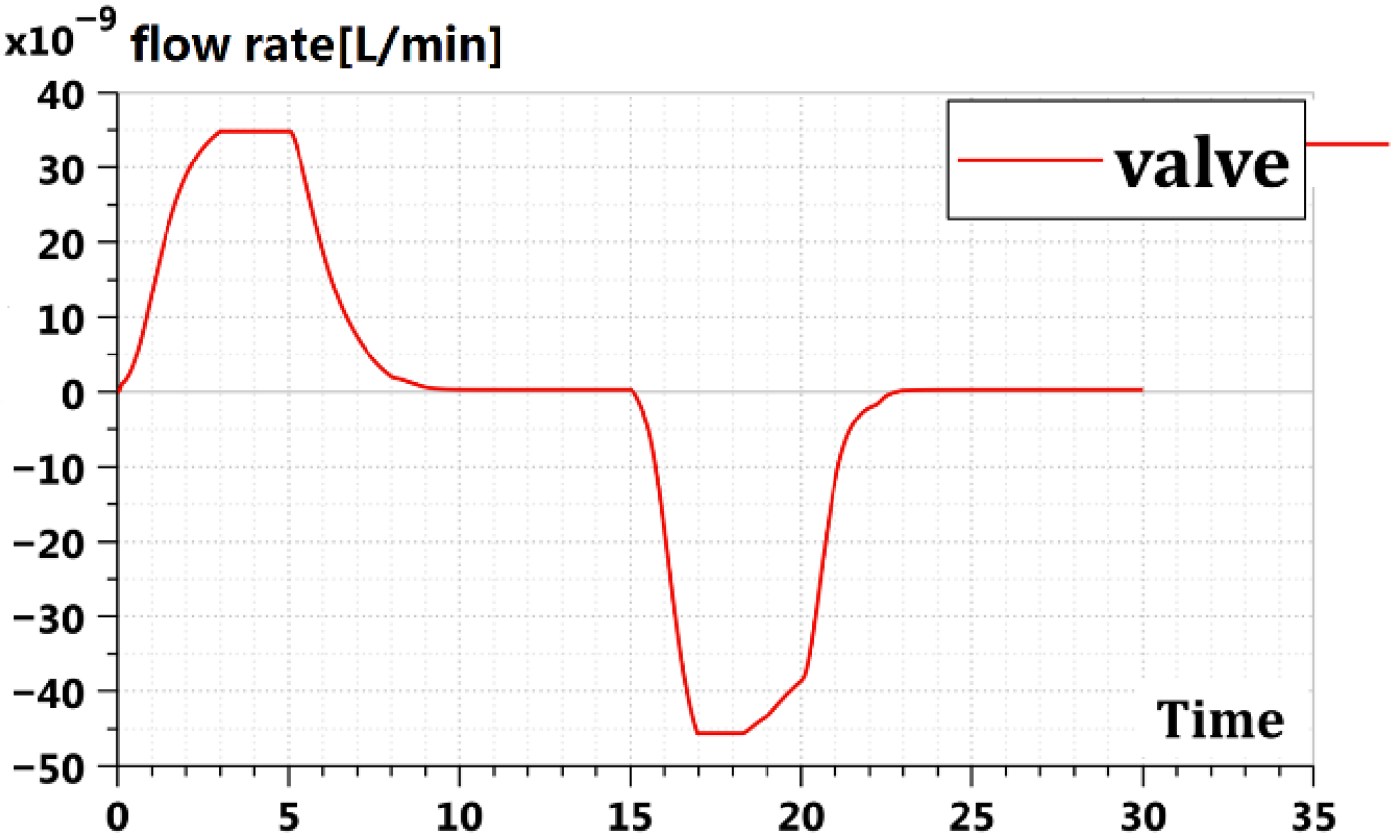
Through the simulation, as shown in the curves in Figure 24 and Figure 25, it was found that the coupling flow between the pump and the valve in the new circuit is small, which is less than 5% of the total flow. It verifies that the new circuit can better solve pump-valve coupling problems. In the new circuit, valve opening changes can perfectly control the pump flow in and out. Therefore, the coupling between the pump and the valve can be restrained. By contrast, the proposed compound circuit fundamentally suppresses the pressure-flow coupling mechanism through two core topological design measures.
First, the oil supply pressure of the valve-controlled open circuit is set to be slightly higher than the set pressure of the safety valve in the pump-controlled closed circuit, which forms a stable pressure gradient matching between the two circuits. This gradient ensures that the flow output by the pump and valve can be superposed smoothly to the hydraulic cylinder without reverse flow caused by excessive pressure difference; this avoids the shunt loss of the pump circuit flow to the valve circuit or the valve circuit flow to the pump circuit. Second, the hydraulic operated check valves and relief valves configured in the pump-controlled closed circuit form a passive flow balance mechanism: the hydraulic operated check valves automatically compensate for the volume difference of the asymmetric cylinder cavities and the system leakage flow in real time, maintaining the pressure stability of the two chambers of the pump; the relief valves limit the maximum output pressure of the pump circuit, avoiding pressure mutation in the pump circuit due to load change and thus preventing the sudden generation of coupling flow caused by instantaneous pressure difference between the two circuits. In addition, the adaptive three-stage control strategy further weakens the dynamic coupling mechanism: in different operation phases, the circuit reasonably distributes the flow output ratios of the pump and valve, and the smooth switching mechanism based on the first-order inertial link delay signals avoids the sudden change of pump/valve flow output during mode switching, which eliminates the dynamic coupling flow caused by the abrupt change of the flow field. It is the synergistic effect of the above pressure-flow matching topology design and dynamic control strategy optimization that blocks the core generation mechanism of pump-valve coupling interference, thus reducing the coupling flow to less than 5% of the total flow and realizing the effective suppression of pump-valve coupling in the parallel circuit.
4.7. Comparison of Control Strategies
To further clarify the technical advantages and innovation of the proposed pump-valve compound circuit and its adaptive control strategy, this subsection conducts a systematic comparative analysis with representative pump-valve compound control methods reported in the existing scientific literature.
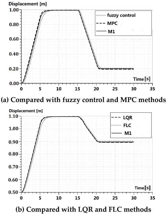
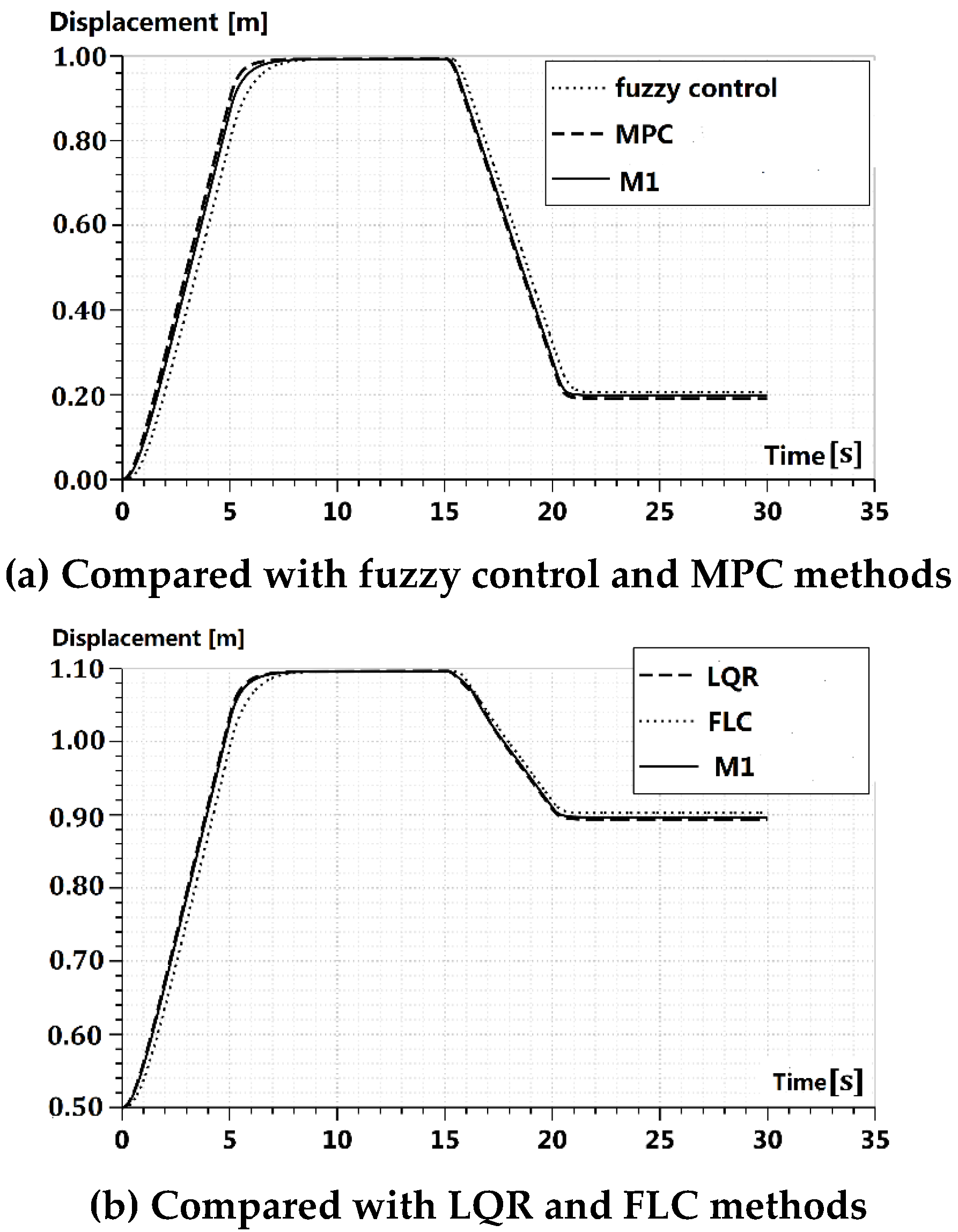
Different control strategies are used to simulate the pump-valve parallel system, and the corresponding position curve is shown in Figure 26. These comparative control methods include fuzzy control [17], MPC [26], LQR [25], FLC [27], etc. Here, for the convenience of comparison, the proposed method of this paper is recorded as M1.
Figure 26.
Comparison of different control strategies.
It can be seen from Figure 26 that when the system is disturbed by a different load, the displacement control effect of the proposed method is not affected by the change of the load force, which suppresses the influence of the load disturbance on the control accuracy. For load force changes, the adaptive three-stage control strategy can adjust the pump-valve flow output ratio in real time according to the actual load characteristics, and the smooth switching mechanism based on first-order inertial link delay signals can maintain the stability of mode conversion, resulting in only a slight change in the system’s rise time and positioning accuracy without obvious overshoot or operational shocks. For common external disturbances, such as hydraulic source pressure fluctuations and small load impacts, the PID position feedback control combined with the pressure-stabilizing effect of relief valves and the hydraulic operated check valves in the circuit can quickly suppress disturbance effects, with the displacement tracking error remaining within the allowable range of the system and with no sustained oscillation of the hydraulic cylinder.
In this paper, the error indicators of Root Mean Squared Error (RMSE), Mean Absolute Error (MAE), and Mean Relative Error (MRE) are used to compare the error between the position curve of different control methods and the given curve during the total operation process. The smaller the RMSE, MAE, and MRE values, the better the system control performance. The corresponding error results are shown in Table 2.
Table 2.
Comparison of different control methods.
From Table 2, it can be seen that compared with other control methods, the M1 error of the proposed method is the smallest in the whole operation process of the system. For the four control strategy architecture, the pump-valve compound control schemes in [17,25,26,28] only adopt fixed coupling control or simple on–off switching logic, without hierarchical division of the system’s operating phases (dynamic acceleration, steady-speed operation, precision positioning) and cannot adaptively adjust the control main body according to different performance requirements. This results in the loss of either dynamic performance or energy efficiency in the partial working phases. The proposed adaptive three-stage control strategy makes up for this defect: it reasonably allocates the working modes of pump-valve parallel drive, pump-dominated drive, and valve-dominated drive for different operating phases, fully exploiting the high dynamic performance of the valve-controlled circuit and the high energy efficiency of the pump-controlled circuit, and realizing the full-process optimization of system performance from dynamic start-up to precision positioning.
4.8. Sensitivity Analysis
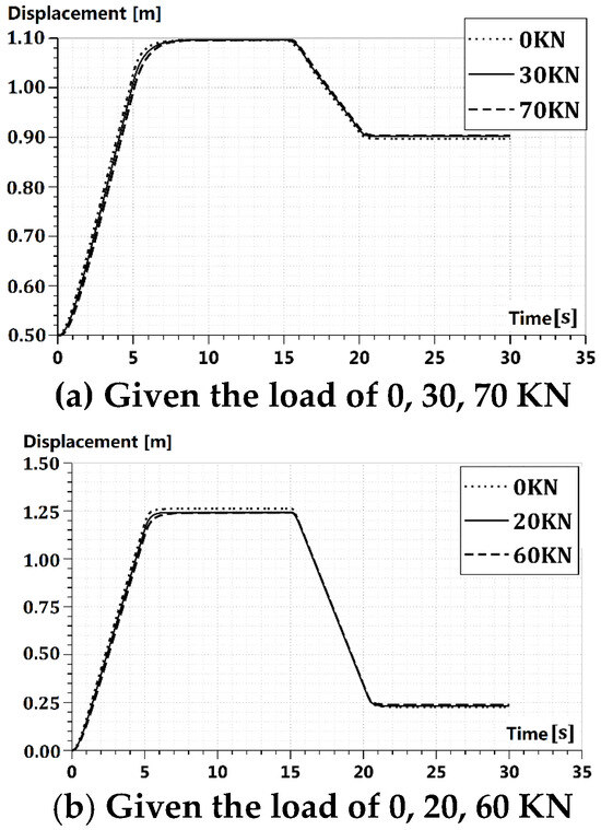
To verify the robustness of the proposed scheme to load quality changes or external disturbances, two different sets of loads such as 0 KN, 30 KN, and 70 KN and 0 KN, 20 kN, and 60 kN are given in this paper, and sensitivity analysis is performed as shown in Figure 27.
Figure 27.
Simulation results under different load disturbances.
It can be seen from Figure 27 that when the system is disturbed by the different load, the displacement control effect of the proposed method is not affected by the change of the load force, which suppresses the influence of the load disturbance on the control accuracy. For load force changes, the adaptive three-stage control strategy can adjust the pump-valve flow output ratio in real time according to the actual load characteristics, and the smooth switching mechanism based on first-order inertial link delay signals can maintain the stability of mode conversion, resulting in only a slight change in the system’s rise time and positioning accuracy without obvious overshoot or operational shocks. For common external disturbances such as hydraulic source pressure fluctuations and small load impacts, the PID position feedback control combined with the pressure-stabilizing effect of relief valves and hydraulic operated check valves in the circuit can quickly suppress disturbance effects, with the displacement tracking error remaining within the allowable range of the system and with no sustained oscillation of the hydraulic cylinder.
5. Conclusions
The paper proposes a novel parallel hydraulic architecture to simultaneously achieve high dynamic performance and high energy efficiency in applications such as ship lifts and multi-DOF platforms, overcoming the limitations of traditional valve-controlled or pump-controlled systems. The design integrates a valve-controlled open circuit for fast, high-precision positioning with a pump-controlled closed circuit for large-flow, energy-efficient coarse motion, eliminating the single-chamber pre-load issue of direct pump designs. An adaptive three-stage control strategy parallel operation during acceleration/deceleration, pump dominant control at constant speed, and valve-dominant control for precise positioning ensures smooth transitions via a first-order inertial delay mechanism. AMESim simulations confirm that the system matches the fast response of valve control while achieving the efficiency of pump control, maintaining chamber pre-load to enhance rigidity and natural frequency, and limiting pump valve coupling flow to under 5%, thereby providing a practical and robust solution for high-performance hydraulic systems. Compared with different control methods, the effectiveness of the proposed method was proved.
When evaluating the retrofitting cost and complexity compared with existing commercial hydraulic systems (mainly pump-controlled or valve-controlled independent systems), the proposed circuit features low retrofitting difficulty and controllable additional cost. Meanwhile, this study also has obvious inherent limitations that need to be pointed out: first, the impact of sensor latency and measurement errors on the real-time performance of circuit decision-making and mode switching under harsh industrial working conditions; second, the asynchronous dynamic response between the pump and valve caused by their inherent structural and performance differences as well as factors such as mechanical wear and oil compressibility in actual operation, which may affect the accuracy of flow superposition and system dynamic response. In addition, the authors could also explore other deployment-related issues, such as the decline of system performance due to the aging of key hydraulic components during long-term operation, the adaptability of the fixed-parameter control strategy to variable working conditions like load mutation and oil temperature change, and the integration and miniaturization difficulties of the circuit system in application scenarios with strict space constraints. This would make the research conclusions more comprehensive and provide clearer directions for the subsequent engineering application and optimization of the proposed method.
In the future, subsequent research will focus on making up for this limitation by carrying out two aspects of work: first, building a physical experiment platform of the pump-valve compound circuit, and conducting experimental verification under actual industrial working conditions with variable load mass and oil bulk modulus to calibrate and revise the simulation model; second, optimizing the existing adaptive control strategy by introducing online monitoring of load mass and oil bulk modulus, and designing a parameter self-tuning mechanism to make the control strategy adapt to the variation of key working condition parameters. This would improve the engineering robustness of the proposed circuit and control method in actual application.
At the same time, a pump valve composite hydraulic circuit hardware test bench will be built based on the simulation parameters of the paper, to confirm the simulation performance through experimental hardware testing.
Author Contributions
B.W.: Investigation, Methodology, Validation, Writing—original draft. Y.B.: Conceptualization, Data curation, Writing—review and editing, Funding acquisition. All authors have read and agreed to the published version of the manuscript.
Funding
This work is supported by the Taiyuan Institute of Technology Scientific Research Initial Funding (No. 2024KJ040); Excellent Doctor Award Fund for Working in Shanxi Province (No. 2025LJ023); Scientific and Technological Innovation Programs of Higher Education Institutions in Shanxi (No. 2025L122).
Data Availability Statement
Data will be made available on request.
Conflicts of Interest
The authors declare that they have no known conflicts—competing financial interests or personal relationships—that could have appeared to influence the work reported in this paper.
Abbreviations
The specific meaning of all the mathematical symbols in this paper is explained here.
| oil pressure | ||
| elastic bulk modulus of oil | ||
| servo valve rated current | ||
| servo valve rated differential pressure | ||
| servo valve rated flow | ||
| relief valve pressure | ||
| relief valve flow | ||
| hydraulic operated check valve pressure | ||
| hydraulic operated check valve flow | ||
| pump capacity | ||
| hydraulic cylinder diameter | ||
| diameter of piston rod | ||
| hydraulic cylinder stroke | ||
| dead zone volume of two cavities | ||
| coefficient of viscous friction | ||
| load quality | ||
| hydraulic cylinder acceleration | ||
| hydraulic cylinder displacement difference (m) | ||
| motor input power (w) | ||
| servo valve input power (w) | ||
| load output power (w) | ||
| cylinder output power (w) | ||
| given displacement (m) | ||
| actual displacement (m) | ||
| servo valve frequency | ||
| servo valve damping ratio | ||
| system efficiency | ||
References
- Yang, M.; Yan, G.; Zhang, Y.; Zhang, T.; Ai, C. Research on high efficiency and high dynamic optimal matching of the electro-hydraulic servo pump control system based on NSGA-II. Heliyon 2023, 9, e13805. [Google Scholar] [CrossRef] [Scilit] [PubMed]
- Qu, S.; Zappaterra, F.; Vacca, A.; Busquets, E. An electrified boom actuation system with energy regeneration capability driven by a novel electro-hydraulic unit. Energy Convers. Manag. 2023, 293, 117443. [Google Scholar] [CrossRef] [Scilit]
- Jia, X.; Zhou, D. Multi-variable anti-disturbance controller with state-dependent switching law for adaptive cycle engine. Energy 2024, 288, 129845. [Google Scholar] [CrossRef] [Scilit]
- Jin, R.; Huang, H.; Li, L.; Zuo, H.; Gan, L.; Ge, S.S.; Liu, Z. Artificial intelligence enabled energy-saving drive unit with speed and displacement variable pumps for electro-hydraulic systems. IEEE Trans. Autom. Sci. Eng. 2023, 21, 3193–3204. [Google Scholar] [CrossRef] [Scilit]
- Ranjan, P.; Wrat, G.; Bhola, M.; Mishra, S.K.; Das, J. A novel approach for the energy recovery and position control of a hybrid hydraulic excavator. ISA Trans. 2020, 99, 387–402. [Google Scholar] [CrossRef] [Scilit]
- Ali, H.H.; Mustafa, A.W.; Al-Bakri, F.F. A new control design and robustness analysis of a variable speed hydrostatic transmission used to control the velocity of a hydraulic cylinder. Int. J. Dyn. Control 2021, 9, 1078–1091. [Google Scholar] [CrossRef] [Scilit]
- Xu, B.; Ding, R.; Zhang, J.; Cheng, M.; Sun, T. Pump/valves coordinate control of the independent metering system for mobile machinery. Autom. Constr. 2015, 57, 98–111. [Google Scholar] [CrossRef] [Scilit]
- Ahn, K.K. Triad of three system: AI-driven hydraulics for autonomous electric excavators with sustainable energy savings. Autom. Constr. 2025, 180, 106543. [Google Scholar] [CrossRef] [Scilit]
- Wang, A.; Lv, Z.; Gao, Y.; Quan, L.; Huang, J. Potential energy recovery scheme with variable displacement asymmetric axial piston pump. Proc. Inst. Mech. Eng. Part I J. Syst. Control. Eng. 2020, 234, 875–887. [Google Scholar] [CrossRef] [Scilit]
- Zhang, X.; Quan, L.; Yang, Y.; Wang, C.; Yao, L. Output characteristics of a series three-port axial piston pump. Chin. J. Mech. Eng. 2012, 25, 498–505. [Google Scholar] [CrossRef] [Scilit]
- Quan, Z.; Quan, L.; Zhang, J. Review of energy efficient direct pump controlled cylinder electro-hydraulic technology. Renew. Sustain. Energy Rev. 2014, 35, 336–346. [Google Scholar] [CrossRef] [Scilit]
- Ketelsen, S.; Padovani, D.; Andersen, T.O.; Ebbesen, M.K. Classification and review of pump-controlled differential cylinder drives. Energies 2019, 12, 1293. [Google Scholar] [CrossRef] [Scilit]
- Chen, H.; Fu, Y.L.; Chen, J.; Liu, H.S. Research on the New Missile Actuation System with Dual Independent Closed-Loop. Appl. Mech. Mater. 2014, 551, 337–343. [Google Scholar] [CrossRef] [Scilit]
- Do, T.C.; Dang, T.D.; Dinh, T.Q.; Ahn, K.K. Developments in energy regeneration technologies for hydraulic excavators: A review. Renew. Sustain. Energy Rev. 2021, 145, 111076. [Google Scholar] [CrossRef] [Scilit]
- Li, J.; Li, W.; Liang, H.; Kong, L. Review of research on improved PID control in electro-hydraulic servo system. Recent Pat. Eng. 2024, 18, 54–68. [Google Scholar] [CrossRef] [Scilit]
- Modala, V.; Patra, S.; Ray, G. Observer-based Controller Design for Linear Time-varying Delay Systems using a New Lyapunov-Krasovskii Functional. Int. J. Autom. Control 2021, 15, 99–123. [Google Scholar] [CrossRef] [Scilit]
- Li, J.; Li, W.; Du, X. Research on the characteristics of electro-hydraulic position servo system of RBF neural network under fuzzy rules. Sci. Rep. 2024, 14, 15332. [Google Scholar] [CrossRef] [Scilit]
- Zheng, K.; Zhang, Q.; Hu, Y.; Wu, B. Design of fuzzy system-fuzzy neural network-backstepping control for complex robot system. Inf. Sci. 2021, 546, 1230–1255. [Google Scholar] [CrossRef] [Scilit]
- Zhang, B.; Enyan, M.; Junsen, R.; Xinxing, Z.; Hongyu, L. Position control of electro-hydraulic servo system based on repetitive control strategy. Recent Pat. Mech. Eng. 2024, 17, 260–280. [Google Scholar] [CrossRef] [Scilit]
- Yang, Y.; Shao, X.; Shi, Y.; Zhang, W. Back-stepping robust control for flexible air-breathing hypersonic vehicle via α-filter-based uncertainty and disturbance estimator. Int. J. Control Autom. Syst. 2021, 19, 753–766. [Google Scholar] [CrossRef] [Scilit]
- Nguyen, M.H.; Ahn, K.K. Output feedback robust tracking control for a variable-speed pump-controlled hydraulic system subject to mismatched uncertainties. Mathematics 2023, 11, 1783. [Google Scholar] [CrossRef] [Scilit]
- Mitsou, E.; Fanizza, G.; Grimm, N.; Yoo, J. Cutting out the cosmological middle man: General Relativity in the light-cone coordinates. Class. Quantum Gravity 2021, 38, 055011. [Google Scholar] [CrossRef] [Scilit]
- Xu, J.; Sui, Z.; Wei, X. Singular Perturbation Decoupling and Composite Control Scheme for Hydraulically Driven Flexible Robotic Arms. Processes 2025, 13, 1805. [Google Scholar] [CrossRef] [Scilit]
- Gao, Y.; Liu, C.; Jiang, S.; Zhang, S. Zero-sum differential games-based fast adaptive robust optimal sliding mode control design for uncertain missile autopilot with constrained input. Int. J. Control 2022, 95, 1789–1801. [Google Scholar] [CrossRef] [Scilit]
- Tu, T. Synergistic integration of LQR control and PSO optimization for advanced active suspension systems utilizing electro-hydraulic actuators and electro-servo valves. EMITTER. Int. J. Eng. Technol. 2025, 13, 56–72. [Google Scholar] [CrossRef] [Scilit]
- Tang, X.; Wu, C.; Xu, X. Learning-based nonlinear model predictive controller for hydraulic cylinder control of ship steering system. J. Mar. Sci. Eng. 2022, 10, 2033. [Google Scholar] [CrossRef] [Scilit]
- Zhang, M.; Lyu, F.; Li, C.; Li, X.; Wu, M. The roadheader auto-rectification dynamic analysis and control based on the roadway floor mechanic characteristics. Arab. J. Sci. Eng. 2021, 46, 2649–2661. [Google Scholar] [CrossRef] [Scilit]
- Chen, J.; Du, X.; Fei, Z.; Xia, W.; Sun, X.M. A fuzzy logic based approach to measure complex load dynamics for accurate motion control of hydraulic actuators. IEEE Trans. Instrum. Meas. 2024, 73, 7502612. [Google Scholar] [CrossRef] [Scilit]
- Saad, S.; Zellouma, L. Fuzzy logic controller for three-level shunt active filter compensating harmonics and reactive power. Electr. Power Syst. Res. 2009, 79, 1337–1341. [Google Scholar] [CrossRef] [Scilit]

Disclaimer/Publisher’s Note: The statements, opinions and data contained in all publications are solely those of the individual author(s) and contributor(s) and not of MDPI and/or the editor(s). MDPI and/or the editor(s) disclaim responsibility for any injury to people or property resulting from any ideas, methods, instructions or products referred to in the content. |
© 2026 by the authors. Licensee MDPI, Basel, Switzerland. This article is an open access article distributed under the terms and conditions of the Creative Commons Attribution (CC BY) license.