


Abstract
This paper presents an overview of fault-tolerance strategies in multilevel converters, with emphasis on fault diagnosis as a fundamental stage. Classical multilevel converter topologies and their main application areas, such as motor drives, renewable energy systems, and smart grids, are first introduced, along with the most common faults affecting power semiconductor devices. Fault diagnosis techniques reported in the literature are then reviewed and classified into model-based, signal-based, hardware-based, and hybrid approaches. The operating principles, measured variables, and implementation requirements of each category are analyzed, with particular attention to the fault detection times. A comparative analysis is provided, highlighting the fastest diagnostic strategies and their application to different multilevel converter topologies. This review consolidates recent advances and identifies current trends and challenges, providing a useful reference for the development of faster and more reliable fault-tolerant solutions in multilevel power converters.
1. Introduction
DC–AC converters are fundamental for converting DC voltage into AC power, and their reliability is crucial, particularly in critical applications where a failure can severely compromise the overall system performance. In sectors such as medicine and the automotive industry, it is essential that these converters operate continuously, even under fault conditions. For instance, in medical devices or electronic braking systems in vehicles, an interruption in the output voltage could have severe consequences [1,2,3]. A common strategy to improve reliability is the use of redundant systems, where multiple converters are connected in parallel to ensure backup in the event of a failure. However, this approach increases costs due to the addition of extra components [4,5]. Therefore, it is essential to implement fault diagnosis solutions and tolerance mechanisms that protect the most failure-prone components, such as power switches and capacitors, ensuring that the system can react appropriately before a major problem occurs [6].
In DC–AC converters, semiconductor devices and capacitors are key components and are frequently used. Failures in these elements account for a high percentage of breakdowns in such systems. Figure 1 illustrates the distribution of failure probabilities in multilevel converters. The data indicate that power devices are the most prone to failure, accounting for 31% of reported cases, followed by aluminum electrolytic capacitors at 18%, gate driver circuits at 15%, and connectors at 11%. Inductors and resistors contribute to 5% and 2% of failures, respectively, while the remaining faults are grouped under “others” [7,8]. These converters, like other power electronics energy conversion systems, are subjected to additional stress factors, including thermal, electrical, and mechanical stress. Therefore, understanding the distribution of these stressors and the susceptibility of the components is crucial for improving converter reliability [9].
Figure 1.
Percentage distribution of failures in electronic components of power converters.
Due to the occurrence of faults in converters, several authors have proposed diagnostic strategies aimed at mitigating them and maintaining normal system operation, or at least ensuring an acceptable degraded performance. The main objective of both fault diagnosis and fault tolerance is to detect and identify any anomaly at an early stage, in order to prevent unexpected shutdowns and proactively plan maintenance actions [10,11,12]. Developing a fault diagnosis system represents a fundamental step for DC–AC converters, as it helps prevent catastrophic failures in system semiconductors. Fault-tolerant strategies, on the other hand, enable the converter to continue operating without interruption, even when power switches are in a fault condition [13,14,15].
Multilevel converters (MLCs) have emerged as an effective solution to reduce the probability of failures due to their modular architecture, which enables the distribution of voltage stress among multiple power switches. This distribution decreases the electrical stress on each component, thereby extending its lifetime and improving reliability [16,17]. In addition, various studies have proposed modifications to optimize these topologies, such as reducing the number of components, which further lowers the likelihood of failures. These properties, combined with the ease of implementing fault diagnosis and tolerance strategies, allow multilevel converter-based systems to continue operating under degraded conditions while internal issues are resolved. Collectively, these advantages position multilevel converters as a superior alternative to classical topologies, standing out for their efficiency, flexibility, and resilience [18,19].
Unlike previous review studies addressing fault diagnosis and fault-tolerant operation in power converters, this paper focuses specifically on multilevel DC–AC converter topologies and their associated fault diagnosis strategies. Particular emphasis is placed on fault detection speed and system behavior under faulty conditions, highlighting the practical importance of rapid and reliable detection for maintaining operational continuity. Recent advances based on intelligent and data-driven techniques are also examined within the framework of multilevel converter applications.
While existing surveys generally provide descriptive summaries of diagnostic and tolerance methods, limited attention has been given to a performance-oriented comparison centered on reported fault detection times. The main contribution of this review lies in the systematic synthesis of detection time data across different converter topologies and fault categories, explicitly distinguishing between simulation-based analyses and experimentally validated results. By positioning detection speed as a central evaluation criterion, this work offers a structured perspective that supports a clearer assessment of practical feasibility and real-world applicability.
The remainder of this manuscript is organized as follows. Section 2 introduces the principal multilevel converter topologies, including CHB, FC, NPC, and MMC structures, outlining their operating principles and structural characteristics relevant to fault analysis. Section 3 describes the main industrial and energy-related applications in which multilevel converters are employed, with particular emphasis on reliability requirements. Section 4 presents a comprehensive review of fault diagnosis strategies, focusing on reported detection times and validation approaches. Section 5 provides a detailed discussion of the reviewed methods and their practical implications. Finally, Section 6 summarizes the main findings and outlines future research directions aimed at achieving faster and more robust fault detection in practical multilevel converter systems.
2. Multilevel Converter
Multilevel converters are advanced electronic devices that surpass the characteristics of traditional two-level converters by offering a greater number of voltage levels in the output signal. Their operation depends on the type of power supply employed, which determines whether they function as a voltage source converter (VSC) or a current source converter (CSC) [20,21]. MLCs are widely used in high-power applications, such as power transmission in electrical grids and electric motor control [22,23]. They have also proven effective in other areas, including energy storage systems and renewable energy generation [24,25]. Thanks to their ability to generate waveforms with lower harmonic distortion and to achieve high voltage levels with components of lower nominal ratings. MLCs have emerged as a strong alternative to two-level converters, especially in demanding industrial applications. These characteristics make them an ideal solution in environments where energy efficiency, signal quality, and reliability are critical.
The operating principle of multilevel converters is based on synthesizing multiple levels of direct current (DC) voltage, which are combined to generate a stepped waveform that approximates a sinusoidal signal. This is achieved by summing multiple input sources and applying an appropriate switching strategy. As a result, the generated waveforms exhibit lower harmonic distortion, reducing the need for passive filters or transformers [26,27,28]. Over the last decades, different MLC structures have been proposed. However, the literature highlights three main topologies: the cascaded H-bridge (CHB), the flying capacitor (FC), and the neutral-point clamped (NPC) converter. These configurations have been extensively studied and applied in various case studies [29,30]. In many studies, these topologies are further modified to enhance performance, reduce costs, optimize efficiency, or meet the specific requirements of each application [31,32].
Nevertheless, other topologies have also been developed, such as modular multilevel converters (MMC), which are widely employed in medium- and high-voltage applications. These converters stand out for their ability to handle high voltage levels with low harmonic distortion, in addition to offering a modular and flexible design architecture [23,33,34]. Within this category, hybrid modular multilevel converters (HMMC) have been introduced to overcome some of the limitations of conventional MMCs by integrating different technologies and architectures. This configuration combines various semiconductor devices, such as IGBTs and MOSFETs, enabling higher efficiency and improved operational performance [35]. An overview of the main multilevel converter topologies is presented in Figure 2.
Figure 2.
Classification of multilevel converters.
2.1. Cascaded H-Bridge Multilevel Converter (CHB)
The cascaded H-bridge (CHB) multilevel converter topology is based on the series connection of several three-level converters, commonly implemented through H-bridges. Each of these converters generates three voltage levels: , 0, and , and they are powered by independent DC sources [36,37]. The main advantage of this configuration is the elimination or reduction of clamping diodes, which simplifies the overall system design and improves efficiency [38,39]. Figure 3 illustrates the structure of cascaded H-bridge multilevel inverters. The figure shows both three- and five-level configurations, supplied by symmetric sources. These configurations provide output voltage waveforms that closely resemble sinusoidal signals, making them suitable for power systems applications where high power quality is required.
Figure 3.
CHB Multilevel Converter: (A) Three-level configuration with a single H-bridge cell; (B) Five-level configuration with two H-bridge cells and symmetric sources.
To calculate the number of output levels in a cascaded multilevel converter with symmetrical DC sources, the following Equation (1) is used:
where:
m: represents the number of independent DC voltage sources.
These converters are notable for their ability to generate output waveforms with multiple voltage levels, resulting in improved waveform quality and a significant reduction in harmonic content. However, their implementation also presents certain challenges related to control complexity, the increased number of required components, and the efficient management of modules and power sources [40,41]. The main advantages that have driven the adoption of cascaded multilevel converters, as well as the disadvantages to consider in their design and practical implementation, are described below:
Main Advantages
- Improved waveform quality: By increasing the number of voltage levels, a waveform closer to a pure sinusoid is achieved, reducing harmonic content and improving performance in sensitive applications.
- Modularity: The cascaded structure allows a modular design, facilitating scalability and maintenance.
- Reduced component stress: Voltage is shared among multiple semiconductor devices, extending their lifespan.
- Design flexibility: This topology is suitable for both low- and high-power applications, making it versatile in diverse industrial and energy environments.
Main Disadvantages
- Control complexity: A higher number of levels demands more sophisticated modulation strategies and precise switching synchronization, requiring advanced algorithms and high-performance digital controllers.
- Higher probability of failure: The increased number of components raises the likelihood of faults, especially in harsh environments.
- Implementation cost: Achieving a higher number of voltage levels requires more electronic devices and power sources.
Within the classification of cascaded H-bridge (CHB) converters, two fundamental configurations can be distinguished according to the type of DC sources employed: symmetric and asymmetric topologies [42,43].
- Symmetric CHB MLCs require sources of equal magnitude, which simplifies the design but limits the number of achievable levels.
- Asymmetric CHB MLCs allow the use of sources with different values, and through strategic selection, the number of levels can be maximized without proportionally increasing the number of modules.
This classification directly affects the resulting waveform and the complexity of control. Figure 3 illustrates the distinction between symmetric and asymmetric configurations. Proper implementation of this topology optimizes system performance in industrial applications, motor drives, and power generation. Additionally, an appropriate switching strategy reduces switching losses and improves the system’s energy efficiency [44,45]. Accordingly, Table 1 presents the switching sequence used to obtain the five output voltage levels in the CHB converter.
Table 1.
Switching sequence to obtain 5 output voltage levels in the CHB converter.
2.2. Neutral-Point Clamped (NPC) Multilevel Converter
The neutral-point clamped (NPC) multilevel converter topology is characterized by dividing the supply voltage among the levels through the use of series-connected clamping diodes [46,47]. In this configuration, the DC bus voltage is distributed across four capacitors, so that both the voltage across each capacitor and the blocking voltage of the switches correspond to Vdc/4. The clamping diodes provide specific current paths during the switching states, which allows the output voltage to be limited to defined levels and prevents overvoltages [48]. Figure 4 shows both symmetric and asymmetric NPC configurations. Subplot (A) illustrates a three-level symmetric configuration, while subplot (B) depicts a five-level configuration, which may be asymmetric depending on the DC voltage distribution.
Figure 4.
NPC Multilevel Converter: (A) Three-level; (B) Five-level.
Equation (2) is used to determine the number of output levels (n) in a neutral-point clamped (NPC) multilevel converter. Equation (3) allows calculating the number of required switching devices (S), while Equation (4) defines the number of clamping diodes (D) needed in the topology. (C) denotes the number of capacitors connected to the DC bus.
Table 2 below shows the switching sequence corresponding to the 5-level configuration of the multilevel converter with interlocked diodes. This information allows to visualize how the switches are managed to generate the different output voltage levels in each case.
Table 2.
Switching sequence to obtain 5 output voltage levels in the NPC converter.
Once the operating principle of the neutral-point clamped (NPC) multilevel converter, as well as its structure and switching states, are understood, it is essential to identify its main advantages and limitations to ensure proper selection according to the intended application. This analysis enables the evaluation of its feasibility based on factors such as control complexity, efficiency, component requirements, and the characteristics of the final application. The most relevant points of this topology are detailed below:
Main Advantages
- Requires a reduced number of capacitors to generate the different voltage levels.
- No transformers are required, simplifying the design and minimizing costs.
Main Disadvantages
- Capacitor voltages must be maintained in balance, which complicates the control system.
- Diodes capable of conducting the converter’s nominal current are necessary.
- Fast-recovery clamping diodes are essential.
2.3. Floating Capacitor (FC) Multilevel Converter
The floating capacitor (FC) multilevel converter topology is characterized by the use of capacitors that are not directly connected to a ground reference (Figure 5). These floating capacitors allow the creation of different voltage levels by combining the switching states of the power devices. This type of converter has been implemented in various applications, especially in photovoltaic systems, where DC energy must be converted to AC for injection into the electrical grid. The use of floating capacitors contributes to voltage balancing among the different levels, resulting in a smoother output waveform with reduced harmonic distortion [49,50,51].
Thanks to these characteristics, this topology emerges as an excellent alternative for renewable energy systems, providing higher power quality and a more efficient response to load variations or environmental conditions.
Figure 5.
FC Multilevel Converter: (A) Three-level; (B) Five-level.
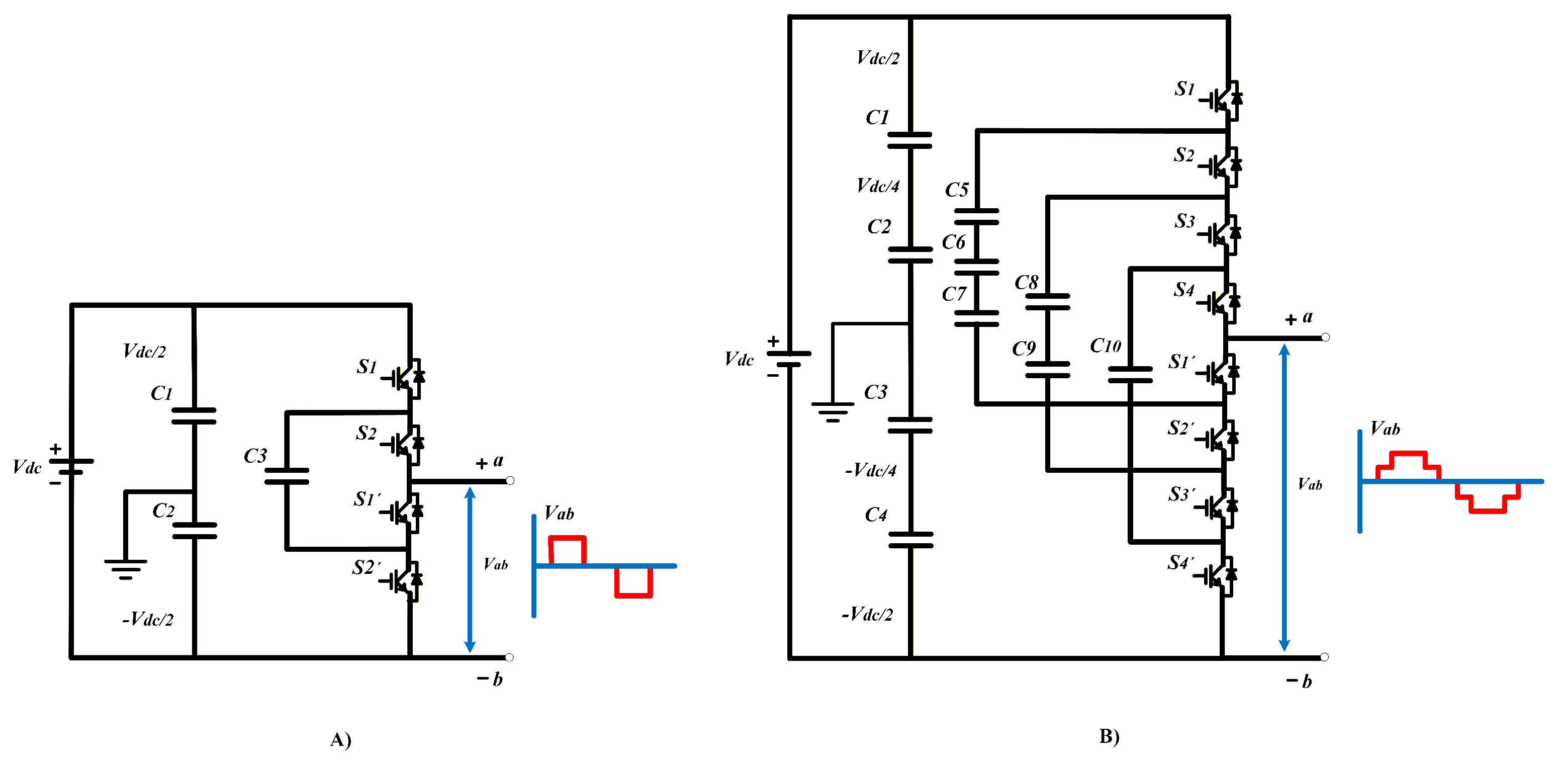
After presenting the topology, it is important to establish how the number of capacitors required for this architecture is determined. In particular, the number of floating capacitors needed (F) depends on the desired number of voltage levels (n) and is calculated using the following equation:
In this configuration, multiple redundant switching states are associated with each output voltage level. These redundant states are an inherent feature of the flying capacitor (FC) topology and play a crucial role in the regulation and balancing of the capacitor voltages. By properly selecting among the available redundant switching combinations, it is possible to actively control the charging and discharging processes of the flying capacitors, thereby ensuring stable converter operation and a uniform voltage distribution across the energy storage elements.
Table 3 summarizes the switching states used to generate the five output voltage levels of the FC converter, explicitly including the redundant combinations employed for balancing the flying capacitor voltages.
Table 3.
Switching sequence to obtain 5 levels of output voltage in the FC converter.
Once the floating capacitor (FC) converter topology has been analyzed, its main advantages and disadvantages can be identified as follows:
Main Advantages
- Elimination of clamping diodes: This topology does not require clamping diodes, reducing the possibility of faults associated with these devices and simplifying the circuit design.
- Efficient voltage regulation: Voltage control of the floating capacitors is achieved through the proper management of the converter’s redundant states, resulting in stable and efficient operation.
- Independent voltage balancing: The voltage of the floating capacitors can be balanced individually in each branch of the converter, thereby facilitating control and enhancing the system’s dynamic performance.
Main Disadvantages
- High number of capacitors: This configuration requires a considerable number of floating capacitors, increasing system complexity, volume, and total implementation cost.
- Conduction capability requirements: Floating capacitors must be capable of continuously conducting the load current, which imposes stricter technical requirements on component selection and sizing.
- Resonance risk: The presence of multiple capacitors in the structure can induce resonance conditions, potentially affecting the stability and performance of the converter if not properly mitigated.
After a detailed analysis of the characteristics and operation of the three main multilevel converter topologies, it is pertinent to perform a direct comparison of their primary attributes. Table 4 presents a comparative summary that highlights the key differences in terms of the number of switches, complexity, voltage levels, and other relevant features. This overview provides a clearer understanding of the advantages and disadvantages of each configuration, as well as the applications in which they are commonly employed.
Table 4.
Technical Comparison of Multilevel Converter Topologies: CHB, NPC, and FC.
When selecting a multilevel converter topology, it is essential to consider not only the intended application, operating voltage, and power rating, but also the inherent trade-offs between system complexity, implementation cost, and control requirements. As illustrated in Table 4, although the CHB, NPC, and FC topologies utilize a comparable number of power switches, they differ considerably in the type and quantity of passive components, which directly affects complexity, cost, and energy efficiency. For instance, the CHB topology allows for simpler modular control but requires multiple isolated DC sources; the NPC reduces semiconductor stress with fewer capacitors yet necessitates active voltage balancing; and the FC topology provides improved voltage balancing at the expense of a higher component count and cost. These distinctions emphasize the importance of aligning the converter topology with specific operational requirements. While all three topologies exhibit robust performance across a range of applications, the growing demand for higher power, greater efficiency, and enhanced flexibility has driven the development of advanced architectures, such as the modular multilevel converter (MMC), which addresses several limitations inherent to conventional designs.
2.4. Modular Multilevel Converter (MMC)
Modular multilevel converters represent one of the most recent and versatile topologies in the field of power conversion for medium- and high-voltage applications. Their design is based on a highly scalable and modular structure that not only allows efficient operation at high voltages but also provides superior waveform quality with low harmonic distortion. These characteristics have contributed to their increasing adoption in power transmission systems, high-capacity industrial motor drives, and environments where high operational reliability is required.
In an MMC, the power stage is composed of multiple submodules (SMs) connected in series to form the upper and lower arms of each phase, as illustrated in Figure 6, each submodule typically implements a half-bridge cell, or in specific configurations, a full-bridge cell accompanied by a capacitor, whose function is to contribute to the stepped generation of the output voltage. In this manner, the output voltage is obtained as the sum of the voltages of the capacitors in the activated submodules at a given instant. Additionally, each arm incorporates a series inductor, known as the “arm inductor,” which limits the rate of change of current (di/dt) and reduces harmonic content, thereby improving the system’s dynamic performance and stability.
Figure 6.
Configuration and waveform of a modular multilevel inverter: (A) Five-level; (B) Seven-level.
Main Advantages:
- Modularity: The structure allows increasing the number of voltage levels by adding additional submodules, without significant modifications to the main design.
- Reduced switching stress: In these topologies, the IGBTs switch at lower frequencies, which decreases the electrical stress on the semiconductor devices.
- High efficiency: This topology can achieve efficiencies of up to 98
- Active capacitor balancing facilitates the implementation of advanced control strategies to dynamically regulate capacitor voltages.
The MMC is widely used due to its high scalability, efficiency, and fault resilience, making it particularly suitable for high-voltage applications (above 100 kV). In contrast, conventional topologies such as CHB, NPC, and FC require more complex insulation and protection systems to operate at similar voltage levels. The modular design of the MMC inherently allows for redundancy, enabling the rapid disconnection of faulty submodules (SMs). However, this advantage comes with increased control complexity and a larger component count, which may raise implementation effort and computational demands.
Table 5 provides a comparative summary of classical and modular multilevel topologies, highlighting the trade-offs in modularity, control requirements, fault tolerance, and harmonic performance.
Table 5.
Comparison of features between classical multilevel converter topologies (CHB, NPC, and FC) and the modular multilevel converter (MMC).
As shown in Table 5, the MMC is distinguished by its high modularity and excellent scalability, enabling the rapid isolation of faulty submodules without interrupting system operation. This capability is particularly critical in high-voltage or large-scale applications, where continuous operation is essential. In comparison, CHB offers moderate fault tolerance with partial redundancy, while NPC and FC provide lower fault tolerance, often requiring complete shutdowns or external backup schemes. Although the MMC delivers these advantages, it comes with increased control complexity and a higher component count, raising both computational and implementation demands. CHB achieves relatively low total harmonic distortion (THD) with simpler control, whereas NPC and FC exhibit moderate THD (5–8%) but with less modularity, highlighting the trade-offs between fault tolerance, harmonic performance, and system complexity. Table 6 further details these trade-offs by comparing fault-tolerance strategies across multilevel converters, emphasizing isolation capabilities, post-fault reconfiguration, and the ease of implementing diagnostic mechanisms.
Table 6.
Comparison of fault-tolerance capabilities among different multilevel converter topologies.
In conclusion, the MMC demonstrates superior robustness and flexibility against potential faults compared to CHB, NPC, and FC topologies, primarily due to its modularity and high fault tolerance. Conventional topologies show limitations in fault isolation, operational continuity, and maintenance, often requiring full shutdowns or manual intervention.
The MMC supports advanced diagnostic strategies that detect faults rapidly and enables reconfiguration approaches that maintain operation with minimal performance loss. Although this comes with increased control complexity and higher implementation costs, the overall balance between performance, reliability, and flexibility makes MMC the optimal choice for large-scale, critical applications.
By providing both quantitative and qualitative comparisons of THD, fault-tolerance capabilities, and control requirements, this analysis highlights the inherent trade-offs in selecting multilevel converter topologies, offering practical guidance for implementations across various industrial and power electronics sectors.
3. Applications of Multilevel Converters
Currently, multilevel converters (MLCs) are employed in various sectors that demand high levels of efficiency, reliability, and precise voltage and current control. In recent years, the most relevant applications have been in high-voltage direct current (HVDC) transmission systems, particularly for long-distance transmission [52,53], medium-voltage distribution networks integrating energy storage systems [54,55,56], and renewable energy systems [57,58,59], such as photovoltaic (PV) panels [60,61,62] and wind turbines Generator (WTG) [63,64].
MLCs enable efficient DC-AC energy conversion, optimizing the power quality injected into the grid, facilitating the integration of hybrid systems, and enhancing the performance of electric motor drives [65,66]. Additionally, they provide precise control of charge and discharge in energy storage systems, particularly in battery-based systems (ESS) [67,68] and supercapacitors [69], improving voltage and current fluctuations and ensuring optimal energy management [70,71].
Another key application of MLCs is in the drive of induction and DC motors. In these cases, the converters enable more precise control of torque and speed, thereby reducing switching losses and harmonic distortion, minimizing motor heating, and extending the equipment’s operational lifespan [72].
Table 7 provides an overview of key applications for multilevel converters (MLCs). Examining the details highlights the compromises involved in choosing a topology. Modular types, such as MMC and HMMC, are commonly used in high-power motor drives and industrial systems, where precise control and scalability are crucial, but they require more sophisticated control strategies and a larger number of components, adding to system complexity. On the other hand, traditional topologies like CHB, NPC, and MCHB are favored in renewable energy and storage solutions, as they offer simpler designs and lower hardware needs, though with some limits in scalability and slightly higher harmonic distortion. Metrics like THD and the number of voltage levels help to assess the trade-off between performance, efficiency, and design complexity.
Table 7.
Applications of multilevel converters in different sectors and their main characteristics.
When compared to the highest reported THD, it becomes clear that topologies such as MCHB (17 levels) and MMC produce lower harmonic distortion in high-power systems, but they require more switching devices and more advanced control strategies. In contrast, simpler topologies like NPC (9 levels) show higher THD in photovoltaic applications, yet they are easier to implement and demand less computational effort. This comparison provides a clear view of the trade-offs between control complexity, diagnostiC.A.-C.racy, and implementation costs across various applications.
In summary, Table 7 shows that modular topologies (MMC and HMMC) dominate in high-power applications and motor control, while classical configurations such as CHB, NPC, and MCHB are more common in renewable energy systems (PV and WT) and energy storage systems. This comparison indicates that the selection of a topology directly depends on the power, control, and efficiency requirements of the specific case study, consolidating MLCs as versatile and essential technologies for the modernization of electrical grids and industrial power systems.
4. Fault Diagnosis Strategies in Multilevel Converters
The use of multilevel converters has proven advantageous in various applications, especially those requiring medium- and high-voltage operation. However, their configuration involves a larger number of semiconductor devices, which increases the probability of faults. Among the most common faults in these converters are open-circuit and short-circuit failures [11,85].
Open-circuit faults occur when a gate signal is applied to a power semiconductor device, but the device fails to conduct as expected under normal conditions, preventing current flow through the corresponding branch [86]. Short-circuit faults, on the other hand, occur when a semiconductor device conducts without receiving a gate signal, allowing uncontrolled current flow and generating a current crossover between branches, which can cause significant damage to the converter [87].
These faults not only affect system continuity but can also generate additional stress on other system components (resistors, capacitors, etc.), increase THD levels, and compromise the stability of the converter’s output voltage. Therefore, rapid identification and the implementation of reliable diagnostic strategies are crucial for minimizing damage and ensuring system safety. Figure 7 illustrates these types of faults, providing a clearer visualization of the concepts described above.
Figure 7.
Types of faults in power semiconductor devices: (A) short-circuit and (B) open-circuit.
4.1. Fault Diagnosis
To detect and mitigate failures in multilevel converters, it is necessary to implement a fault diagnosis system. This system is responsible for identifying the presence of faults, locating their origin, determining the type, and assessing their severity. According to [88], fault diagnosis methodologies can be classified into four main categories: hardware-based diagnosis, model-based diagnosis, signal processing-based diagnosis, and hybrid algorithm-based diagnosis. Figure 8 presents a general scheme of these aforementioned strategies.
Figure 8.
Classification of fault diagnosis strategies applied to MLCs.
The following sections provide a more detailed description of each of these strategies, focusing on their operating principles, advantages, and disadvantages, as well as specific schemes for each one. This classification enables designers to select an appropriate technique that meets the specific requirements of the case study.
4.1.1. Hardware-Based Fault Diagnosis
The hardware-based approach represents the first line of defense in fault diagnosis for multilevel converters, enabling rapid and direct detection of abnormal behaviors. In this method, sensors measure physical quantities such as current, voltage, or semiconductor states, or the converter’s input and output signals are used to identify potential faults [89]. Power semiconductor devices are particularly vulnerable, with faults appearing either as open-circuit (interruption of conduction) or short-circuit (undesired conduction). To address these issues, voltage and current sensors monitor abnormal conditions, while gate signal analysis ensures proper transistor operation [90]. Although these components provide clear benefits, their selection involves trade-offs between diagnostic speed, computational load, and hardware complexity, which are critically evaluated below.
Table 8 summarizes studies that use different hardware components for fault diagnosis in multilevel converters. Beyond describing their primary functions, key trade-offs are evident: current sensors provide fast fault detection but increase system complexity, voltage sensors are simple to implement but may fail to capture rapid transients, and optocouplers offer isolation and effective monitoring while introducing moderate latency. This assessment helps identify the most suitable solutions based on system constraints and diagnostic objectives.
Table 8.
Hardware elements and sensing devices used for fault detection and localization in MLCs.
To better illustrate the practical integration of these elements to hardware-based fault diagnosis, Figure 9 shows a general scheme applied to a MLC, where the voltage and current sensors, together with the optocouplers (isolators), send information to the control stage, which is responsible for identifying faults and subsequently for reconfiguration through decision making.
Figure 9.
Step-by-step representation of the hardware-based fault diagnosis strategy in MLCs.
4.1.2. Model-Based Fault Diagnosis
The use of small electronic devices in multilevel converter modules has led to significant changes in fault detection strategies. Classical hardware-based techniques, which relied on sensors and actuators for measurement and monitoring, have given way to diagnostic methods based on analytical redundancy. This approach relies on mathematical models that describe the physical and dynamic behavior of the system. Predefined models of the converter are combined with advanced techniques, such as neural networks or fuzzy logic, to provide more accurate and robust diagnostics, particularly in complex systems [94,95].
Table 9 summarizes the main elements that comprise this strategy, along with several case studies that illustrate key characteristics of the work and the strategy employe. Subsequently, Figure 10 shows schematically how these fault diagnosis strategies are implemented.
Table 9.
Model-based diagnostic strategies for fault detection in MLCs.
Figure 10.
Flow diagram of the model-based fault diagnosis strategy for MLCs.
Model-based diagnosis is conducted in two primary stages. In the first, the actual system output is compared to the output predicted by the model, generating a signal known as a residual. These residuals remain small under normal conditions, but increase significantly when a fault occurs, allowing their identification. Depending on the method implemented, the residuals can be scalar values (indicating the presence of a fault) or vectors (providing detailed information about multiple faults).
In the second stage, the residuals are transmitted to the decision-making units, which are responsible for identifying and isolating faults. These units may employ simple comparison thresholds to complex statistical or artificial intelligence methods [4]. Model-based fault diagnosis strategies have gained popularity due to their ability to operate without additional sensors, making them a more economical and practical solution in modern applications. Their implementation has proven effective in detecting and identifying faults in complex systems, thereby increasing the reliability and efficiency of multilevel converters [99].
4.1.3. Fault Diagnosis Based on Signal Processing
Fault detection using a signal-based approach is the preferred diagnostic technique for nonlinear systems, as it does not require detailed knowledge of the system’s mathematical model. Instead, a model is derived from experimental data and measured signals. This approach establishes a direct correspondence between the system’s inputs and outputs, allowing validity to be generated even in the presence of unknown inputs. Signal-based diagnostics has gained relevance due to its ability to model complex and nonlinear systems without the need to describe the dynamic behavior of multilevel converters in detail. Additionally, it is particularly useful when the system is not well-modeled or cannot be represented mathematically. In these cases, a fuzzy model can be created based on empirical or experimental knowledge of the system behavior.
The methods presented in Table 10 allow a better understanding of the most commonly used diagnostic strategies for fault detection under the signal processing approach. Each approach offers specific advantages, depending on the type of signal, the presence of noise, and the need to detect faults in real-time. Figure 11 illustrates schematically the principle of operation of signal-based diagnostics, showing how signals are captured, processed, and analyzed to identify possible faults in an MLC.
Table 10.
Diagnostic strategies based on the signal approach in MLCs.
Figure 11.
Methodology of the Signal-Based Fault Diagnosis Strategy for MLCs.
4.1.4. Fault Diagnosis Based on Hybrid Algorithms
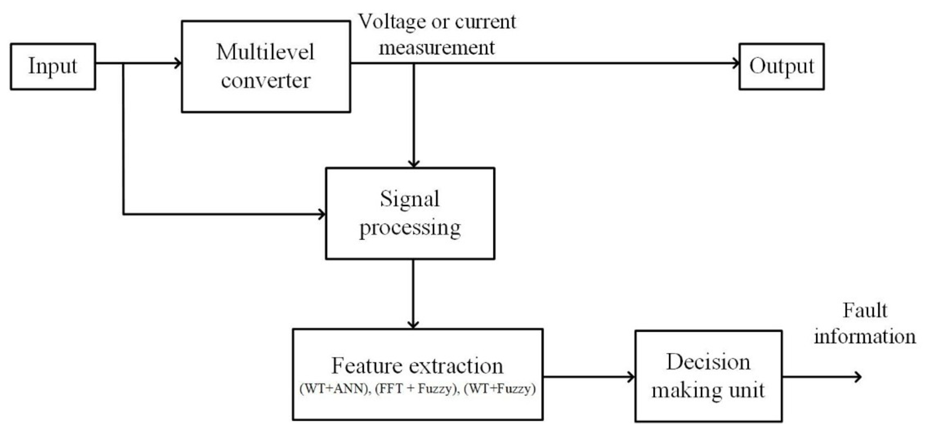
Hybrid diagnosis leverages the best of signal processing and intelligent models, proving particularly useful in case studies where rapid response and robustness to noise are crucial. On the other hand, it is also widely applied in contexts where systems are nonlinear. For example, it can use signal processing for preliminary detection and then activate a model-based algorithm to confirm and isolate the fault [102,103]. It also optimizes the use of computational resources by applying only the level of processing required for each specific situation. This approach is scalable, allowing it to be implemented in a wide variety of converters and applications, from simple systems to more complex structures.
Hybrid diagnostic techniques combine the strengths of different approaches to enhance accuracy and robustness in detecting faults in MLC. As shown in Table 11, the most common combinations are: Wavelet Transform with Artificial Neural Networks, Fast Fourier Transform with Fuzzy Logic, and Wavelet Transform with Fuzzy Logic. However, there are still not so many works focused on multilevel converters. These strategies have demonstrated great potential for capturing information in the frequency domain, including intelligent classification capability, and offer a promising framework for future research.
Figure 12 illustrates the general approach for implementing hybrid diagnostic strategies in multilevel converters. It can be seen that the measured signals of the converter (voltage or current) are processed to extract relevant information using one of the techniques (WT + ANN, FFT + Fuzzy, WT + Fuzzy). Afterwards, these extracted characteristics are analyzed in a decision unit that determines if a fault is present and of what type, providing key information to ensure the safe operation of the system.
Table 11.
Comparison of hybrid diagnostic strategies in MLCs.
Figure 12.
Flow diagram of hybrid fault diagnosis strategies in MLCs.
4.2. Comparison of Diagnostic Strategies
Once the main diagnostic strategies have been analyzed, it becomes clear that each of them has advantages and disadvantages, depending on the context in which they are implemented. Hardware-based diagnostics are characterized by being simple and fast to detect faults; however, they depend on additional sensors, which increases the cost of implementation and makes control more difficult [110]. In contrast, the signal-based strategy offers a faster response speed compared to the others, and it does not depend on the mathematical model. This leads to a more limited accuracy.
On the other hand, the model-based diagnostic strategy stands out for being more accurate, as it utilizes mathematical models that accurately represent the system’s behavior, enabling the detection of incipient faults and small variations. However, this type of strategy requires an exhaustive knowledge of the converter and a greater computational effort, which can complicate a real-time implementation. Finally, hybrid strategies emerge as a robust alternative, combining speed and simplicity in signal processing with enhanced accuracy and adaptability across various models. However, these techniques are complex in design and have a significant computational burden, which may limit their application in certain scenarios [111].
Table 12 presents a comparative overview of the main fault diagnosis strategies. Rather than merely summarizing the previous sections, the table highlights the trade-offs between diagnostic speed, computational load, sensor requirements, and implementation complexity. This structured comparison allows for a more critical evaluation of each approach.
Table 12.
Practical comparison of diagnostic strategies: time, noise, and applicability.
No single fault diagnosis strategy is universally optimal, as each approach involves trade-offs between diagnostic speed, computational load, sensitivity, and implementation complexity. Hardware-based strategies offer very fast detection and low computational requirements but rely on a larger number of sensors and have limited capability for detecting incipient faults. Signal-based methods balance speed and sensitivity, albeit with higher computational demand. Model-based strategies improve the detection of incipient faults but are slower and more resource-intensive. Hybrid strategies aim to integrate the advantages of different approaches, balancing speed, accuracy, and complexity, although their implementation can be more challenging and costly. This critical evaluation highlights the strengths and limitations of each method, supporting the selection of the most appropriate strategy according to priorities such as diagnostic speed, precision, and operational constraints.
4.3. Fault Detection Times and Diagnostic Techniques Reported in the Literature
One of the critical factors in fault diagnosis is time. It is essential to detect the fault immediately after its occurrence to avoid prolonged system downtime. Rapid detection not only increases system safety and reliability but also ensures operational continuity. Rapid diagnosis allows faults to be isolated before they cause major damage to the power semiconductor devices, leading to reduced output signal quality or interruptions in operation when the converter is operating with the load connected [112,113]. In real cases operating at high voltage, a delay of a few milliseconds may be enough to cause damage to the converter due to overcurrents or even trigger cascading faults that compromise the quality of the output signal.
This section presents works from various authors reporting diverse fault diagnosis techniques and detection times. However, comparisons in multilevel converters should be addressed distinctly: simulation-based validation and experimental validation. Studies with experimental validation reflect real operating conditions, accounting for delays, noise, and hardware non-idealities. In contrast, works based solely on simulation often assume idealized scenarios that may underestimate detection times. Therefore, analyzing both approaches separately allows for a more realistic assessment of technique performance and practical feasibility.
Table 13 presents some fault diagnosis studies that detect short-circuit and open-circuit faults in multilevel converters in a fast manner. In the table, you can see the times reported in the literature.
Table 13.
Fault diagnosis strategies and detection times reported in the literature with experimental validation.
The studies summarized in Table 13 demonstrate significant progress in fault diagnosis techniques for multilevel converters, particularly in terms of diagnostiC.A.-C.racy, robustness, and experimental validation. Most of the proposed approaches rely on advanced signal processing strategies and data-driven methods, which enable fast and reliable fault detection under a wide range of operating conditions. Notably, the reported diagnostic times consistently lie within the millisecond range, underscoring the suitability of these techniques for real-time applications and safety-critical systems. However, the inherent trade-off between computational complexity and detection speed remains a key challenge, especially for hybrid and machine learning-based techniques, which often demand high-quality measurements, large training datasets, and careful parameter tuning. Despite these limitations, the experimental validation provided in all studies confirms the practical feasibility of the proposed methods and further emphasizes their relevance for industrial applications.
Likewise, studies validated exclusively through simulation, while useful for analyzing trends, comparing strategies, and assessing the theoretical performance of fault diagnosis techniques, should be interpreted with caution. The lack of experimental validation implies that relevant practical aspects, such as measurement noise, acquisition and processing delays, hardware non-idealities, and computational constraints, are not fully considered, which may lead to an overestimation of actual performance. In this context, although the reported detection times are often highly competitive, their reproducibility in physical environments cannot be guaranteed. Table 14 summarizes studies based solely on simulation, enabling the identification of relevant advances while also highlighting the need for rigorous experimental validation to support their applicability in real-world systems.
Table 14.
Fault diagnosis strategies and detection times reported in the literature based solely on simulation validation.
Finally, the joint analysis of techniques with and without experimental validation reveals that approaches supported by experimental results provide a more realistic and reliable assessment of fault diagnosis performance in multilevel converters, thereby constituting a stronger foundation for their adoption in practical applications. In contrast, methods validated solely through simulation, although valuable for conceptual exploration and the initial development of new strategies, exhibit inherent limitations due to their inability to fully capture real operating conditions. In this regard, experimental validation emerges as a key factor in ensuring the robustness, reproducibility, and industrial feasibility of the proposed techniques.
5. Discussion
The comparative review of fault diagnosis and fault-tolerant strategies in multilevel converters confirms the strong dependence between diagnostic performance and the selected approach. Hardware-based techniques remain suitable for fast protection tasks; however, their limited flexibility and sensor dependency restrict their applicability in complex multilevel structures. In contrast, signal-based and hybrid strategies demonstrate a more balanced trade-off between detection speed, implementation complexity, and diagnostic capability.
The analysis of reported detection times indicates that signal-based and hybrid methods achieve the fastest responses, typically within the microsecond to millisecond range, making them particularly attractive for applications with strict continuity and reliability requirements. This performance is largely influenced by the choice of measured signals and the use of advanced processing techniques, such as spectral or time–frequency analysis, which enhance fault sensitivity without significantly increasing computational burden.
Furthermore, a clear evolution toward hybrid diagnostic schemes is observed in recent literature. The integration of artificial intelligence with classical observers and signal processing methods enables improved robustness against noise, higher fault classification accuracy, and better adaptability to different operating conditions. These characteristics are especially relevant for high-power and high-voltage multilevel converters, where conventional single-technique approaches often fall short.
Despite these advances, important research gaps remain. There is no unified benchmarking framework for reporting and comparing fault detection times, leading to inconsistencies across studies and limiting objective performance evaluation. Moreover, a substantial portion of the reported results relies on simulation-based validation, while comparatively fewer works demonstrate real-time experimental implementation in full-scale multilevel converter prototypes. Scalability considerations—particularly in high-level-count or high-power configurations—are also insufficiently addressed in many diagnostic approaches. In addition, although artificial intelligence techniques show promising results, detailed discussions regarding hardware constraints, latency, and practical deployment on embedded platforms are often lacking. Addressing these gaps through standardized evaluation criteria and experimentally validated real-time solutions is essential to advance the practical adoption of fault diagnosis strategies in multilevel converters.
6. Conclusions
The comparative analysis of fault diagnosis and fault-tolerant strategies in multilevel converters demonstrates that diagnostic performance is strongly dependent on the selected methodology. Hardware-based techniques offer very fast response times, making them suitable for protection purposes; however, their limited flexibility constrains their use in complex multilevel structures. In contrast, signal-based and hybrid approaches provide a more balanced compromise between detection speed, implementation complexity, and robustness, particularly in applications requiring high reliability and operational continuity.
Recent developments reveal a clear transition toward hybrid frameworks that integrate artificial intelligence with classical signal processing and observer-based techniques. These approaches enhance fault classification accuracy and resilience to noise, especially in high-power and high-voltage multilevel systems where conventional single-method strategies may be insufficient.
Despite these advances, several critical challenges remain. The absence of standardized benchmarking criteria for reporting fault detection times hinders objective comparison across studies. Additionally, many reported results are still limited to simulation-based validation, with relatively few works demonstrating real-time experimental implementation in full-scale prototypes. Scalability and hardware deployment constraints, particularly in high-level-count configurations and embedded platforms, also require further attention. Addressing these issues through unified evaluation frameworks and experimentally validated, real-time solutions is essential to promote the industrial adoption of advanced fault diagnosis strategies in multilevel converters.
Author Contributions
Conceptualization, J.A.G.-F., R.A.V.-M. and A.R.L.; methodology, R.A.V.-M. and A.R.L.; investigation, J.A.G.-F., M.d.C.T.-P. and O.R.-B.; resources, G.L.O.-G. and C.A.-C.; writing—original draft preparation, J.A.G.-F.; writing—review and editing, R.A.V.-M., A.R.L. and G.L.O.-G.; visualization, J.A.G.-F. and O.R.-B.; supervision, R.A.V.-M., A.R.L., G.L.O.-G. and C.A.-C. All authors have read and agreed to the published version of the manuscript.
Funding
The authors would like to thank the funding from Tecnológico Nacional de México (through the project 23120).
Data Availability Statement
No new data were created in this study. Data sharing is not applicable to this article.
Acknowledgments
The authors would like to thank Tecnológico Nacional de México/CENIDET, and the Mexican SECIHTI.
Conflicts of Interest
The authors declare no conflicts of interest.
Abbreviations
The following abbreviations are used in this manuscript:
| DC | Direct Current |
| AC | Alternating Current |
| MLC | Multilevel Converter |
| MMC | Modular Multilevel Converters |
| HMMC | Hybrid Modular Multilevel Converters |
| VSC | Voltage Source Converter |
| CSC | Current Source Converter |
| CHB | cascaded H-Bridge |
| FC | Flying Capacitor |
| NPC | Neutral-Point Clamped |
| SM | Submodule |
| IGBT | Insulated Gate Bipolar Transistor |
| OC | Open Circuit |
| SC | Short Circuit |
| HVDC | High-Voltage Direct Current |
| PV | Photovoltaic Panel |
| WTG | Wind Turbine Generator |
| ESS | Energy Storage System |
| THD | Total Harmonic Distortion |
| MPPT | Maximum Power Point Tracker |
| P&O | Perturb and Observe |
| EKF | Extended Kalman Filter |
| FFT | Fast Fourier Transform |
| DWT | Discrete Wavelet Transform |
| ANN | Artificial Neural Network |
| WT | Wavelet Transform |
References
- Xiao, Q.; Jin, Y.; Jia, H.; Tang, Y.; Cupertino, A.F.; Mu, Y.; Teodorescu, R.; Blaabjerg, F.; Pou, J. Review of fault diagnosis and fault-tolerant control methods of the modular multilevel converter under submodule failure. IEEE Trans. Power Electron. 2023, 38, 12059–12077. [Google Scholar] [CrossRef] [Scilit]
- He, J.; Yang, Q.; Wang, Z. On-line fault diagnosis and fault-tolerant operation of modular multilevel converters—A comprehensive review. CES Trans. Electr. Mach. Syst. 2020, 4, 360–372. [Google Scholar] [CrossRef] [Scilit]
- Ahmad, F.; Adnan, M.; Amin, A.A.; Khan, M.G. A comprehensive review of fault diagnosis and fault-tolerant control techniques for modular multi-level converters. Sci. Prog. 2022, 105, 00368504221118965. [Google Scholar] [CrossRef] [Scilit] [PubMed]
- Gautam, S.P.; Jalhotra, M.; Sahu, L.K.; Kumar, M.R.; Gupta, K.K. A survey on fault tolerant and diagnostic techniques of multilevel inverter. IEEE Access 2023, 11, 60866–60888. [Google Scholar] [CrossRef] [Scilit]
- Aviña-Corral, V.; de Jesus Rangel-Magdaleno, J.; Barron-Zambrano, J.H.; Rosales-Nuñez, S. Review of fault detection techniques in power converters: Fault analysis and diagnostic methodologies. Measurement 2024, 234, 114864. [Google Scholar] [CrossRef] [Scilit]
- Jin, Y.; Xiao, Q.; Jia, H.; Ji, Y.; Dragičević, T.; Teodorescu, R.; Blaabjerg, F. A novel detection and localization approach of open-circuit switch fault for the grid-connected modular multilevel converter. IEEE Trans. Ind. Electron. 2022, 70, 112–124. [Google Scholar] [CrossRef] [Scilit]
- Deng, F.; Lü, Y.; Liu, C.; Heng, Q.; Yu, Q.; Zhao, J. Overview on submodule topologies, modeling, modulation, control schemes, fault diagnosis, and tolerant control strategies of modular multilevel converters. Chin. J. Electr. Eng. 2020, 6, 1–21. [Google Scholar] [CrossRef] [Scilit]
- Flores, J.A.G.; Méndez, R.A.V.; Núnez, A.R.L.; Gordillo, G.L.O.; Pérez, M.d.C.T. Fault diagnosis strategies in multilevel converters. A General Review. Mem. Congr. Nac. Control Autom. 2024, 7, 214–219. [Google Scholar]
- Tian, Y.; Konstantinou, G. Reliability analysis of modular multilevel converters in mvdc applications. e-Prime—Adv. Electr. Eng. Electron. Energy 2024, 9, 100671. [Google Scholar] [CrossRef] [Scilit]
- Ke, L.; Liu, Y.; Yang, Y. Compound fault diagnosis method of modular multilevel converter based on improved capsule network. IEEE Access 2022, 10, 41201–41214. [Google Scholar] [CrossRef] [Scilit]
- An, Y.; Sun, X.; Ren, B.; Zhang, X. Open-Circuit fault diagnosis for a modular multilevel converter based on hybrid machine learning. IEEE Access 2024, 12, 61529–61541. [Google Scholar] [CrossRef] [Scilit]
- Ke, L.; Hu, G.; Yang, Y.; Liu, Y. Fault diagnosis for modular multilevel converter switching devices via multimodal attention fusion. IEEE Access 2023, 11, 135035–135048. [Google Scholar] [CrossRef] [Scilit]
- Pires, V.F.; Cordeiro, A.; Foito, D.; Pires, A.J. Fault-tolerant multilevel converter to feed a switched reluC.A.-C. machine. Machines 2022, 10, 35. [Google Scholar] [CrossRef] [Scilit]
- Jiang, Y.; Shu, H.; Liao, M. Fault-tolerant control strategy for sub-modules open-circuit fault of modular multilevel converter. Electronics 2023, 12, 1080. [Google Scholar] [CrossRef] [Scilit]
- Ahmadi, S.; Poure, P.; Khaburi, D.A.; Saadate, S. A Real-Time Fault-Tolerant Control Approach to Ensure the Resiliency of a Self-Healing Multilevel Converter. Energies 2022, 15, 4721. [Google Scholar] [CrossRef] [Scilit]
- Alqarni, Z.A. Design of active fault-tolerant control system for multilevel inverters to achieve greater reliability with improved power quality. IEEE Access 2022, 10, 77791–77801. [Google Scholar] [CrossRef] [Scilit]
- Nyamathulla, S.; Chittathuru, D.; Muyeen, S. An overview of multilevel inverters lifetime assessment for grid-connected solar photovoltaic applications. Electronics 2023, 12, 1944. [Google Scholar] [CrossRef] [Scilit]
- Li, G.; Liang, J. Modular multilevel converters: Recent applications [history]. IEEE Electrif. Mag. 2022, 10, 85–92. [Google Scholar] [CrossRef] [Scilit]
- Rauf, A.M.; Abdel-Monem, M.; Geury, T.; Hegazy, O. A Review on Multilevel Converters for Efficient Integration of Battery Systems in Stationary Applications. Energies 2023, 16, 4133. [Google Scholar] [CrossRef] [Scilit]
- Barresi, M.; Piegari, L.; Scalabrin, R. Comprehensive assessment of voltage and current source PV-based modular multilevel converters. IET Renew. Power Gener. 2024, 18, 4360–4376. [Google Scholar] [CrossRef] [Scilit]
- Santos, N.I.L.; Vitorino, M.A.; de Rossiter Corrêa, M.B. Novel multilevel current source converter with asymmetric configuration: Analysis, comparison, modulation, and fpga implementation. IEEE J. Emerg. Sel. Top. Power Electron. 2024, 12, 2481–2499. [Google Scholar] [CrossRef] [Scilit]
- Harbi, I.; Rodriguez, J.; Poorfakhraei, A.; Vahedi, H.; Guse, M.; Trabelsi, M.; Abdelrahem, M.; Ahmed, M.; Fahad, M.; Lin, C.H.; et al. Common DC-link multilevel converters: Topologies, control and industrial applications. IEEE Open J. Power Electron. 2023, 4, 512–538. [Google Scholar] [CrossRef] [Scilit]
- Nguyen, V.T.; Kim, J.W.; Lee, J.W.; Park, B.G. Optimal design of a submodule capacitor in a modular multilevel converter for medium voltage motor drives. Energies 2024, 17, 471. [Google Scholar] [CrossRef] [Scilit]
- Das, A.; Kar, A.K.; Kumar, C.; Kumar, U.; Verma, A.; Pal, S.; Joseph, A.; Das, B.; Kasari, P.R.; Chakrabarti, A.; et al. TSBC converter with BESS for DFIG-based wind energy conversion system. IEEE Trans. Ind. Appl. 2020, 56, 6158–6173. [Google Scholar] [CrossRef] [Scilit]
- Liang, G.; Farivar, G.G.; Yadav, G.N.B.; Rodriguez, E.; Pou, J. Battery fault tolerance of modular multilevel converter-based battery energy storage systems with redundant submodules. In Proceedings of the IECON 2021–47th Annual Conference of the IEEE Industrial Electronics Society; IEEE: Piscataway, NJ, USA, 2021; pp. 1–6. [Google Scholar]
- Barros, L.A.; Martins, A.P.; Pinto, J.G. A comprehensive review on modular multilevel converters, submodule topologies, and modulation techniques. Energies 2022, 15, 1078. [Google Scholar] [CrossRef] [Scilit]
- Sun, P.; Tian, Y.; Pou, J.; Konstantinou, G. Beyond the MMC: Extended modular multilevel converter topologies and applications. IEEE Open J. Power Electron. 2022, 3, 317–333. [Google Scholar] [CrossRef] [Scilit]
- Sakib, M.N.; Azad, S.P.; Kazerani, M. A critical review of modular multilevel converter configurations and submodule topologies from DC fault blocking and ride-through capabilities viewpoints for HVDC applications. Energies 2022, 15, 4176. [Google Scholar] [CrossRef] [Scilit]
- Prasad, P.A.V.; Dhanamjayulu, C. An overview on multi-level inverter topologies for grid-tied PV system. Int. Trans. Electr. Energy Syst. 2023, 2023, 9690344. [Google Scholar]
- Rojas, F.; Cardenas, R.; Burgos-Mellado, C.; Espina, E.; Pereda, J.; Pineda, C.; Arancibia, D.; Diaz, M. An overview of four-leg converters: Topologies, modulations, control and applications. IEEE Access 2022, 10, 61277–61325. [Google Scholar] [CrossRef] [Scilit]
- Augustin, A.; Annamalai, T.; Karthikeyan, R. PV Based Modified Cascaded Inverter For Drives Application. In Proceedings of the 2023 9th International Conference on Electrical Energy Systems (ICEES); IEEE: Piscataway, NJ, USA, 2023; pp. 461–466. [Google Scholar]
- Magadum, P.; Sakri, S.G. Five level modified CHB D-STATCOM for harmonic mitigation of EV charging station. J. Integr. Sci. Technol. 2024, 12, 738. [Google Scholar]
- Yin, J.; Dai, N.; Leon, J.I.; Perez, M.A.; Vazquez, S.; Franquelo, L.G. Common-mode-voltage regulation of modular multilevel converters through model predictive control. IEEE Trans. Power Electron. 2024, 39, 7167–7180. [Google Scholar] [CrossRef] [Scilit]
- Liu, Q.; Chen, P.; Liu, S.; Wang, C.; Liu, J. A topology and control method for operational testing of ±800 kV/8 GW flexible DC transmission modular multilevel converter valve. IEEE Access 2024, 12, 55669–55681. [Google Scholar] [CrossRef] [Scilit]
- Motwani, J.K.; Liu, J.; Boroyevich, D.; Burgos, R.; Zhou, Z.; Dong, D. Modeling and control of a hybrid modular multilevel converter for high-AC/low-DC medium-voltage applications. IEEE Trans. Power Electron. 2024, 39, 5371–5385. [Google Scholar] [CrossRef] [Scilit]
- Eroğlu, F.; Kurtoğlu, M.; Eren, A.; Vural, A.M. A novel adaptive state-of-charge balancing control scheme for cascaded H-bridge multilevel converter based battery storage systems. ISA Trans. 2023, 135, 339–354. [Google Scholar] [CrossRef] [Scilit]
- Bernet, D.; Hiller, M. A cascaded H-bridge-based multilevel converter with low energy pulsation for high-power grid applications. IEEE Trans. Power Electron. 2023, 39, 2305–2321. [Google Scholar] [CrossRef] [Scilit]
- Lin, H.; Lin, C.; Xie, D.; Acuna, P.; Liu, W. A counter-based open-circuit switch fault diagnostic method for a single-phase cascaded H-bridge multilevel converter. IEEE Trans. Power Electron. 2023, 39, 814–825. [Google Scholar] [CrossRef] [Scilit]
- Bettoni, S.d.S.; Ramos, H.d.O.; Matos, F.F.; Mendes, V.F. Cascaded h-bridge multilevel converter applied to a wind energy conversion system with open-end winding. Wind 2023, 3, 232–252. [Google Scholar] [CrossRef] [Scilit]
- Benevieri, A.; Cosso, S.; Formentini, A.; Marchesoni, M.; Passalacqua, M.; Vaccaro, L. Advances and Perspectives in Multilevel Converters: A Comprehensive Review. Electronics 2024, 13, 4736. [Google Scholar] [CrossRef] [Scilit]
- Gultekin, B.; Ermis, M. Cascaded multilevel converter-based transmission STATCOM: System design methodology and development of a 12 kV±12 MVAr power stage. IEEE Trans. Power Electron. 2013, 28, 4930–4950. [Google Scholar] [CrossRef] [Scilit]
- Thiyagarajan, V. A new symmetric and asymmetric multilevel inverter circuit with reduced number of components. Mater. Proc. 2022, 10, 5. [Google Scholar]
- Agrawal, N.; Agarwal, A.; Kanumuri, T. Performance analysis of 7-level cascade H-bridge multilevel inverter with symmetrical & asymmetrical configuration. In Proceedings of the 2022 IEEE 10th Power India International Conference (PIICON); IEEE: Piscataway, NJ, USA, 2022; pp. 1–6. [Google Scholar]
- Bashir, S.B.; Ismail, A.A.A.; Elnady, A.; Farag, M.M.; Hamid, A.K.; Bansal, R.C.; Abo-Khalil, A.G. Modular multilevel converter-based microgrid: A critical review. IEEE Access 2023, 11, 65569–65589. [Google Scholar] [CrossRef] [Scilit]
- Chamarthi, P.K.; Muduli, U.R.; El Moursi, M.S.; Al-Durra, A.; Al-Sumaiti, A.S.; Al Hosani, K. Improved pwm approach for cascaded five-level npc h-bridge configurations in multilevel inverter. IEEE Trans. Ind. Appl. 2024, 60, 7048–7060. [Google Scholar] [CrossRef] [Scilit]
- Alatai, S.; Salem, M.; Ishak, D.; Das, H.S.; Alhuyi Nazari, M.; Bughneda, A.; Kamarol, M. A review on state-of-the-art power converters: Bidirectional, resonant, multilevel converters and their derivatives. Appl. Sci. 2021, 11, 10172. [Google Scholar] [CrossRef] [Scilit]
- Munawar, S.; Iqbal, M.S.; Adnan, M.; Akbar, M.A.; Bermak, A. Multilevel inverters design, topologies, and applications: Research issues, current, and future directions. IEEE Access 2024, 12, 149320–149350. [Google Scholar] [CrossRef] [Scilit]
- Hoon, Y.; Mohd Radzi, M.A.; Hassan, M.K.; Mailah, N.F. Control algorithms of shunt active power filter for harmonics mitigation: A review. Energies 2017, 10, 2038. [Google Scholar] [CrossRef] [Scilit]
- Rocha, F.V.; Jacobina, C.B.; Rocha, N.; Queiroz, A.d.P.D. Multilevel converter based on series and parallel connections using floating capacitor. IEEE Trans. Ind. Appl. 2023, 59, 6068–6081. [Google Scholar] [CrossRef] [Scilit]
- Elrais, M.T.; Safayatullah, M.; Batarseh, I. Generalized architecture of a gan-based modular multiport multilevel flying capacitor converter. IEEE Trans. Power Electron. 2023, 38, 9818–9838. [Google Scholar] [CrossRef] [Scilit]
- Kim, J.H.; Park, S.H.; Lee, J.; Cho, J.H.; Cho, G.H.; Kim, H.S. A Floating Voltage Source-Based Turn-Off Snubber for a Nonisolated Multilevel SiC DC-DC Converter. IEEE Trans. Ind. Electron. 2024, 72, 390–400. [Google Scholar] [CrossRef] [Scilit]
- Tian, Y.; Wickramasinghe, H.R.; Li, Z.; Pou, J.; Konstantinou, G. Review, classification and loss comparison of modular multilevel converter submodules for HVDC applications. Energies 2022, 15, 1985. [Google Scholar] [CrossRef] [Scilit]
- Luo, Y.; Liu, C.; He, Z.; Jiang, Y.; Chen, Q. Power Flow Calculation for AC/DC Power Systems with Line-Commutated Converter–Modular Multilevel Converter (LCC-MMC) Hybrid High-Voltage Direct Current (HVDC) Based on the Holomorphic Embedding Method. Electronics 2024, 13, 1877. [Google Scholar] [CrossRef] [Scilit]
- Shahane, R.; Rao, K.N.; Shukla, A. A review on hybrid modular multilevel converters for medium voltage applications. In Proceedings of the 2022 IEEE Energy Conversion Congress and Exposition (ECCE); IEEE: Piscataway, NJ, USA, 2022; pp. 1–8. [Google Scholar]
- Motwani, J.K.; Liu, J.; Burgos, R.; Zhou, Z.; Dong, D. Hybrid modular multilevel converters for high-AC/low-DC medium-voltage applications. IEEE Open J. Power Electron. 2023, 4, 265–282. [Google Scholar] [CrossRef] [Scilit]
- Saha, J.; Panda, S.K. Overview and comparative analysis of bidirectional cascaded modular isolated medium-voltage AC–low-voltage DC (MVAC-LVDC) power conversion for renewable energy rich microgrids. Renew. Sustain. Energy Rev. 2023, 174, 113118. [Google Scholar] [CrossRef] [Scilit]
- Mohammed, M.F.; Qasim, M.A. Single phase T-type multilevel inverters for renewable energy systems, topology, modulation, and control techniques: A review. Energies 2022, 15, 8720. [Google Scholar] [CrossRef] [Scilit]
- Khemili, F.Z.; Bouhali, O.; Lefouili, M.; Chaib, L.; El-Fergany, A.A.; Agwa, A.M. Design of cascaded multilevel inverter and enhanced MPPT method for large-scale photovoltaic system integration. Sustainability 2023, 15, 9633. [Google Scholar] [CrossRef] [Scilit]
- Norambuena, M.; Mora, A.; Garcia, C.; Rodriguez, J.; Aly, M.; Carnielutti, F.; Pereda, J.; Castillo, C.; Zhang, Z.; Yaramasu, V.; et al. Model Predictive Control in Multi-Level Inverters Part II: Renewable Energies and Grid Applications. IEEE Open J. Ind. Appl. 2024, 5, 414–427. [Google Scholar] [CrossRef] [Scilit]
- Bughneda, A.; Salem, M.; Richelli, A.; Ishak, D.; Alatai, S. Review of multilevel inverters for PV energy system applications. Energies 2021, 14, 1585. [Google Scholar] [CrossRef] [Scilit]
- Bana, P.R.; Panda, K.P.; Naayagi, R.; Siano, P.; Panda, G. Recently developed reduced switch multilevel inverter for renewable energy integration and drives application: Topologies, comprehensive analysis and comparative evaluation. IEEE Access 2019, 7, 54888–54909. [Google Scholar] [CrossRef] [Scilit]
- Singh, A.; Jately, V.; Kala, P.; Yang, Y.; Azzopardi, B. Advancements in multilevel inverters for efficient Harnessing of renewable energy: A comprehensive review and application analysis. IEEE Access 2024, 12, 156939–156964. [Google Scholar] [CrossRef] [Scilit]
- Waqas, M.; Jamil, M. Power Quality Improvement Using Nine-Level Cascaded H-Bridge Voltage Source Inverter for PV Applications. In Proceedings of the 2024 12th International Conference on Smart Grid (icSmartGrid); IEEE: Piscataway, NJ, USA, 2024; pp. 429–434. [Google Scholar]
- Barnawi, A.B.; Alfifi, A.R.A.; Elbarbary, Z.; Alqahtani, S.F.; Shaik, I.M. Review of multilevel inverter for high-power applications. Front. Eng. Built Environ. 2024, 4, 77–89. [Google Scholar] [CrossRef] [Scilit]
- Kumar, R.; Singh, B.; Kant, P. Design and analysis of a 54-pulse converter and 7-level hybrid inverter for medium voltage induction motor drive. IEEE Trans. Ind. Appl. 2023, 60, 560–572. [Google Scholar] [CrossRef] [Scilit]
- Pires, V.F.; Foito, D.; Cordeiro, A.; Amaral, T.G.; Chen, H.; Pires, A.; Martins, J.F. Water pumping system supplied by a PV generator and with a switched reluC.A.-C. motor using a drive based on a multilevel converter with reduced switches. Designs 2023, 7, 39. [Google Scholar] [CrossRef] [Scilit]
- Ma, Z.; Jia, M.; Koltermann, L.; Blömeke, A.; De Doncker, R.W.; Li, W.; Sauer, D.U. Review on grid-tied modular battery energy storage systems: Configuration classifications, control advances, and performance evaluations. J. Energy Storage 2023, 74, 109272. [Google Scholar] [CrossRef] [Scilit]
- Xavier, L.S.; De Sousa, C.V.; Pereira, H.A.; Mendes, V.F. Design and performance comparisons of power converters for battery energy storage systems. Int. J. Circuit Theory Appl. 2023, 51, 3146–3166. [Google Scholar] [CrossRef] [Scilit]
- Hernandez, F.D.; Parsegov, S.; Rosas-Caro, J.C.; Bhatnagar, P.; Ibanez, F.M. Optimal number of supercapacitors per submodule in the energy storage system based on a modular multilevel converter with embedded balance control. Int. J. Electr. Power Energy Syst. 2024, 159, 110030. [Google Scholar] [CrossRef] [Scilit]
- Srilakshmi, K.; Kumar, A.; Kondreddi, K.; Krishna, T.M.; Balachandran, P.K.; Gatto, G. Design of solar and energy storage systems fed reduced switch multilevel converter with flower pollination optimization. J. Energy Storage 2024, 99, 113324. [Google Scholar] [CrossRef] [Scilit]
- Lashab, A.; Sera, D.; Hahn, F.; Camurca, L.J.; Liserre, M.; Guerrero, J.M. A reduced power switches count multilevel converter-based photovoltaic system with integrated energy storage. IEEE Trans. Ind. Electron. 2020, 68, 8231–8240. [Google Scholar] [CrossRef] [Scilit]
- Kumara, R.; Singh, B. Performance improvements of power converters for high power induction motor drive. e-Prime—Adv. Electr. Eng. Electron. Energy 2023, 5, 100214. [Google Scholar] [CrossRef] [Scilit]
- Yadav, S.K.; Mishra, N.; Singh, B. Multilevel converter with nearest level control for integrating solar photovoltaic system. IEEE Trans. Ind. Appl. 2022, 58, 5117–5126. [Google Scholar] [CrossRef] [Scilit]
- Sandhu, M.; Thakur, T. Modified cascaded H-bridge multilevel inverter for hybrid renewable energy applications. IETE J. Res. 2022, 68, 3971–3983. [Google Scholar] [CrossRef] [Scilit]
- Zhou, S.; Li, B.; Guan, M.; Zhang, X.; Xu, Z.; Xu, D. Capacitance reduction of the hybrid modular multilevel converter by decreasing average capacitor voltage in variable-speed drives. IEEE Trans. Power Electron. 2018, 34, 1580–1594. [Google Scholar] [CrossRef] [Scilit]
- Mahfuz-Ur-Rahman, A.; Islam, M.R.; Muttaqi, K.M.; Sutanto, D. Model predictive control for a new magnetic linked multilevel inverter to integrate solar photovoltaic systems with the power grids. IEEE Trans. Ind. Appl. 2020, 56, 7145–7155. [Google Scholar] [CrossRef] [Scilit]
- Madhav, G.V.; Kumar, A. Performance Analysis of 9, 11, 13, and 15–Level Back-to-Back Connected Modular Multilevel Converters fed Doubly Fed Induction Machine. Eur. J. Electr. Eng. Comput. Sci. 2023, 7, 35–44. [Google Scholar] [CrossRef] [Scilit]
- Tayari, M.; Guermazi, A.; Ghariani, M. Cascaded Multilevel Inverter for PV-Active Power Filter Combination into the Grid-Tied Solar System. Int. J. Renew. Energy Res. 2020, 10, 1810–1819. [Google Scholar]
- Chen, D.; Xiao, L.; Song, W. Novel hybrid modulation method for modular multilevel converter based energy storage system. IEEE Access 2023, 11, 23420–23432. [Google Scholar] [CrossRef] [Scilit]
- Palani, A.; Mahendran, V.; Vengadakrishnan, K.; Muthusamy, S.; Mishra, O.P.; Ramamoorthi, P.; Maurya, M.R.; Sadasivuni, K.K. A novel design and development of multilevel inverters for parallel operated PMSG-based standalone wind energy conversion systems. Iran. J. Sci. Technol. Trans. Electr. Eng. 2024, 48, 277–287. [Google Scholar] [CrossRef] [Scilit]
- Wang, P.; Xu, H.; Yuan, L. Research on cascaded multilevel converters for dual motor drive systems based on a nine-switch converter. IET Electr. Power Appl. 2024, 18, 849–858. [Google Scholar] [CrossRef] [Scilit]
- Bravo, P.; Pereda, J.; Merlin, M.M.; Neira, S.; Green, T.C.; Rojas, F. Modular multilevel matrix converter as solid state transformer for medium and high voltage AC substations. IEEE Trans. Power Deliv. 2022, 37, 5033–5043. [Google Scholar] [CrossRef] [Scilit]
- Figueroa, F.; Lizana Fuentes, R.; Goetz, S.M.; Rivera, S. Operation of a hybrid energy storage system based on a cascaded multi-output multilevel converter with a carrier-based modulation scheme. Energies 2023, 16, 7150. [Google Scholar] [CrossRef] [Scilit]
- Lee, J.W.; Kim, J.W.; Lee, C.W.; Park, B.G. Common-Mode Voltage Reduction of Modular Multilevel Converter Using Adaptive High-Frequency Injection Method for Medium-Voltage Motor Drives. Energies 2024, 17, 1367. [Google Scholar] [CrossRef] [Scilit]
- Fu, Y.; Meng, Z.; Yang, X.; Ji, L. Open-circuit faults localization with error elimination for modular multilevel converters under various control modes. IEEE J. Emerg. Sel. Top. Power Electron. 2024, 12, 2041–2051. [Google Scholar] [CrossRef] [Scilit]
- Zhou, D.; Qiu, H.; Yang, S.; Tang, Y. Submodule voltage similarity-based open-circuit fault diagnosis for modular multilevel converters. IEEE Trans. Power Electron. 2018, 34, 8008–8016. [Google Scholar] [CrossRef] [Scilit]
- Taul, M.G.; Pallo, N.; Stillwell, A.; Pilawa-Podgurski, R.C. Theoretical analysis and experimental validation of flying-capacitor multilevel converters under short-circuit fault conditions. IEEE Trans. Power Electron. 2021, 36, 12292–12308. [Google Scholar] [CrossRef] [Scilit]
- Mouzakitis, A. Classification of fault diagnosis methods for control systems. Meas. Control 2013, 46, 303–308. [Google Scholar] [CrossRef] [Scilit]
- Ashourloo, M.; Namburi, V.R.; Piqué, G.V.; Pigott, J.; Bergveld, H.J.; El Sherif, A.; Trescases, O. Fault detection in a hybrid Dickson DC–DC converter for 48-V automotive applications. IEEE Trans. Power Electron. 2020, 36, 4254–4268. [Google Scholar] [CrossRef] [Scilit]
- Ashourloo, M.; Namburi, V.R.; Pique, G.V.; Pigott, J.; Bergveld, H.J.; El Sherif, A.; Trescases, O. Robust fault detection of hybrid switched-capacitor dickson converter for fault-tolerant automotive applications. In Proceedings of the 2019 21st European Conference on Power Electronics and Applications (EPE’19 ECCE Europe); IEEE: Piscataway, NJ, USA, 2019; pp. P.1–P.10. [Google Scholar]
- Le, D.D.; Hong, S.; Lee, D.C. Fault detection and tolerant control for flying-capacitor modular multilevel converters feeding induction motor drives. J. Power Electron. 2022, 22, 947–958. [Google Scholar] [CrossRef] [Scilit]
- Khan, F.A.; Shees, M.M.; Alsharekh, M.F.; Alyahya, S.; Saleem, F.; Baghel, V.; Sarwar, A.; Islam, M.; Khan, S. Open-circuit fault detection in a multilevel inverter using sub-band wavelet energy. Electronics 2021, 11, 123. [Google Scholar] [CrossRef] [Scilit]
- Yu, Z.; Yang, W.; Zhang, P.; Zhu, W.; Liu, B.; Hu, C.; Cao, W. Open-Circuit Fault Detection Method for Full-Bridge Modular Multilevel Converter Sub-Modules. In Proceedings of the International Joint Conference on Energy, Electrical and Power Engineering; Springer: Berlin/Heidelberg, Germany, 2023; pp. 206–214. [Google Scholar]
- Liao, Y.; Zhang, Y. Rethinking Model-based fault detection: Uncertainties, risks, and optimization based on a multilevel converter case study. IEEE Trans. Power Electron. 2024, 39, 14229–14239. [Google Scholar] [CrossRef] [Scilit]
- Parimalasundar, E.; Kumar, R.S.; Chandrika, V.S.; Suresh, K. Fault diagnosis in a five-level multilevel inverter using an artificial neural network approach. Electr. Eng. Electromech. 2023, 31–39. [Google Scholar] [CrossRef] [Scilit]
- Song, S.; Lei, J.; Ma, W.; Wang, Y. State Observation-based AC Voltage Measurement Fault Detection for Modular Multilevel Converters. IEEE J. Emerg. Sel. Top. Power Electron. 2025, 13, 3643–3658. [Google Scholar] [CrossRef] [Scilit]
- Pizarro, G.; Poblete, P.; Droguett, G.; Pereda, J.; Núñez, F. Extended Kalman filtering for full-state estimation and sensor reduction in modular multilevel converters. IEEE Trans. Ind. Electron. 2022, 70, 1927–1938. [Google Scholar] [CrossRef] [Scilit]
- Kavitha, N.; Bhavani, N. Fuzzy logic controller based fault tolerant control of multi-level inverters. In Proceedings of the 2024 10th International Conference on Electrical Energy Systems (ICEES); IEEE: Piscataway, NJ, USA, 2024; pp. 1–5. [Google Scholar]
- Khan, S.S.; Wen, H. A comprehensive review of fault diagnosis and tolerant control in DC-DC converters for DC microgrids. IEEE Access 2021, 9, 80100–80127. [Google Scholar] [CrossRef] [Scilit]
- Tang, S.; Wang, J.; Zhang, C.; Wang, D.; Yin, X.; Shuai, Z.; Shen, Z.J. Detection and identification of power device failures using discrete fourier transform for fault-tolerant operation of flying capacitor multilevel converters. IEEE J. Emerg. Sel. Top. Power Electron. 2021, 10, 5081–5091. [Google Scholar] [CrossRef] [Scilit]
- Singh, V.; Yadav, A.; Gupta, S. Combined wavelet and ann-based open-switch fault detection and classification in PV-fed multilevel inverter. J. Inst. Eng. Ser. B 2024, 105, 217–228. [Google Scholar] [CrossRef] [Scilit]
- Wu, H.; Wang, Y.; Liu, Y.; Liu, Y.; Li, Y. An improved switching method-based diagnostic strategy for IGBT open-circuit faults in hybrid modular multilevel converters. IEEE Trans. Power Electron. 2024, 40, 3578–3599. [Google Scholar] [CrossRef] [Scilit]
- Luo, W.; Xie, Z.; Li, Y.; Chen, M.; He, R.; Peng, Y.; Zhang, X. Enhanced 1-D Convolutional Neural Network Based Open-Circuit Fault Diagnosis and Hybrid Fault-Tolerant Control for Three-level NPC Converters. IEEE Trans. Instrum. Meas. 2025, 74, 3545714. [Google Scholar] [CrossRef] [Scilit]
- Parimalasundar, E.; Jayakumar, S.; Dukkipati, S.; Sudha, S.; Sivarajan, S.; Kumar, B.H. A novel approach to fault recognition in multi-level inverters through artificial neural networks. SSRG Int. J. Electr. Electron. Eng. 2024, 11, 161–174. [Google Scholar]
- Zhai, Z.; Wang, N.; Lu, S.; Zhou, B.; Guo, L. A Novel Open Circuit Fault Diagnosis for a Modular Multilevel Converter with Modal Time-Frequency Diagram and FFT-CNN-BIGRU Attention. Machines 2025, 13, 533. [Google Scholar] [CrossRef] [Scilit]
- Gatla, R.K.; Kumar, D.G.; Shashavali, P.; Dsnm, R.; Kotb, H.; Alkuhayli, A.; Ghadi, Y.Y.; Mbasso, W.F. Comprehensive analysis of faults and diagnosis techniques in cascaded multi-level inverters. Heliyon 2024, 10, e39901. [Google Scholar] [CrossRef] [Scilit]
- Ali, M.; Din, Z.; Solomin, E.; Cheema, K.M.; Milyani, A.H.; Che, Z. Open switch fault diagnosis of cascade H-bridge multi-level inverter in distributed power generators by machine learning algorithms. Energy Rep. 2021, 7, 8929–8942. [Google Scholar] [CrossRef] [Scilit]
- Touati, K.O.M.; Merzouk, I.; Kheireddine, M.; Boudiaf, M.; Hafaifa, A. Fuzzy logic based open circuit fault detection and localization in modular multi-level converter (MMC). Soft Comput. 2025, 29, 5591–5612. [Google Scholar] [CrossRef] [Scilit]
- Kheireddine, M.; Merzouk, I.; Hafaifa, A.; Rezk, H.; Mohamed, A.F. A novel fault diagnosis methodology in modular multilevel converters to enhance reliability and resilience. Results Eng. 2025, 27, 105682. [Google Scholar] [CrossRef] [Scilit]
- Naqvi, A.M.; Tripathi, P.; Singh, S. A Topology of Multilevel Inverter for Tolerance against Single and Multiple Faults. J. Sci. Ind. Res. 2025, 84, 219–230. [Google Scholar] [CrossRef] [Scilit]
- Satyanarayana, D.K.; Raghunath, K.; Bharath, K.; Teja, M.; Ramesh, G.; Manikanta, M. Fault Detection and Mitigation in Multilevel Converter by Using Active Fault–Tolerent Control System. Int. J. Mech. Eng. Res. Technol. 2024, 16, 1–12. [Google Scholar]
- Guerrero, J.M.; Blázquez-Campanón, A.; D’Arco, S.; Carrizosa, M.J.; Mahtani, K.; Platero, C.A. A Ground Fault Location and Severity Estimation Method for Modular Multilevel Converters. IEEE Trans. Ind. Appl. 2025, 61, 3944–3957. [Google Scholar] [CrossRef] [Scilit]
- Zhao, S.; Chen, J.; Zhang, C.; He, Y. An online open circuit faults diagnosis method for converter using the lightweight two-channel deep network. Measurement 2025, 243, 116213. [Google Scholar] [CrossRef] [Scilit]
- Amaral, T.G.; Pires, V.F.; Foito, D.; Cordeiro, A.; Rocha, J.I.; Chaves, M.; Pires, A.; Martins, J. A fault detection and diagnosis method based on the currents entropy indexes for the SRM drive with a fault tolerant multilevel converter. IEEE Trans. Ind. Appl. 2023, 60, 520–531. [Google Scholar] [CrossRef] [Scilit]
- Xie, D.; Lin, C.; Zhang, Y.; Sangwongwanich, A.; Ge, X.; Feng, X.; Wang, H. Diagnosis and resilient control for multiple sensor faults in cascaded H-bridge multilevel converters. IEEE Trans. Power Electron. 2023, 38, 11435–11450. [Google Scholar] [CrossRef] [Scilit]
- Guo, K.; Lu, Z.; Liu, P.; Mo, Z. Fault Diagnosis Method for Sub-Module Open-Circuit Faults in Photovoltaic DC Collection Systems Based on CNN-LSTM. Electronics 2025, 14, 1205. [Google Scholar] [CrossRef] [Scilit]
- Yan, Y.; Wu, J.; Cao, Y.; Liu, B.; Li, C.; Shi, T. An Open-Circuit Fault Diagnosis Method for Three-Level Neutral Point Clamped Inverters Based on Multi-Scale Shuffled Convolutional Neural Network. Sensors 2024, 24, 1745. [Google Scholar] [CrossRef] [Scilit]
- Zhang, G.; Li, M.; Gu, X.; Chen, W. Fault diagnosis method for open-circuit faults in NPC three-level inverter based on WKCNN. CES Trans. Electr. Mach. Syst. 2025, 9, 234–245. [Google Scholar] [CrossRef] [Scilit]
- de la Rosa-Mendoza, S.; Alvarez-Salas, R.; Gonzalez-Garcia, M.; Espinosa-Perez, G. Open-circuit switch fault diagnosis of an NPC converter in a DFIG-based WECS. Electric Power Syst. Res. 2026, 252, 112410. [Google Scholar] [CrossRef] [Scilit]
- Liu, Y.; Guo, Z.; Liu, F.; Guo, F.; Wang, K.; Zhu, Y.; Hou, F.; Wang, X. A Real-Time Diagnosis Method of Open-Circuit Faults in Cascaded H-Bridge Rectifiers Based on Voltage Threshold and Current Coefficient of Variation. Electronics 2025, 14, 986. [Google Scholar] [CrossRef] [Scilit]
- Sivapriya, A.; Kalaiarasi, N.; Vishnuram, P.; Abou Houran, M.; Bajaj, M.; Pushkarna, M.; Kamel, S. Real-time hardware-in-loop based open circuit fault diagnosis and fault tolerant control approach for cascaded multilevel inverter using artificial neural network. Front. Energy Res. 2023, 10, 1083662. [Google Scholar] [CrossRef] [Scilit]
- León-Ruiz, Y.; González-García, M.; Alvarez-Salas, R.; Cárdenas, V.; Viera-Diaz, R.I. Fault diagnosis in a photovoltaic grid-tied CHB multilevel inverter based on a hybrid machine learning and signal processing technique. IEEE Access 2024, 12, 128909–128928. [Google Scholar] [CrossRef] [Scilit]
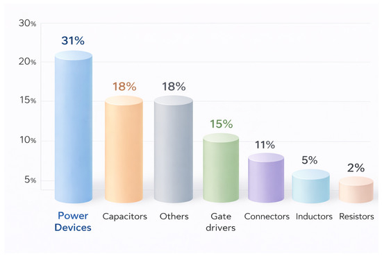
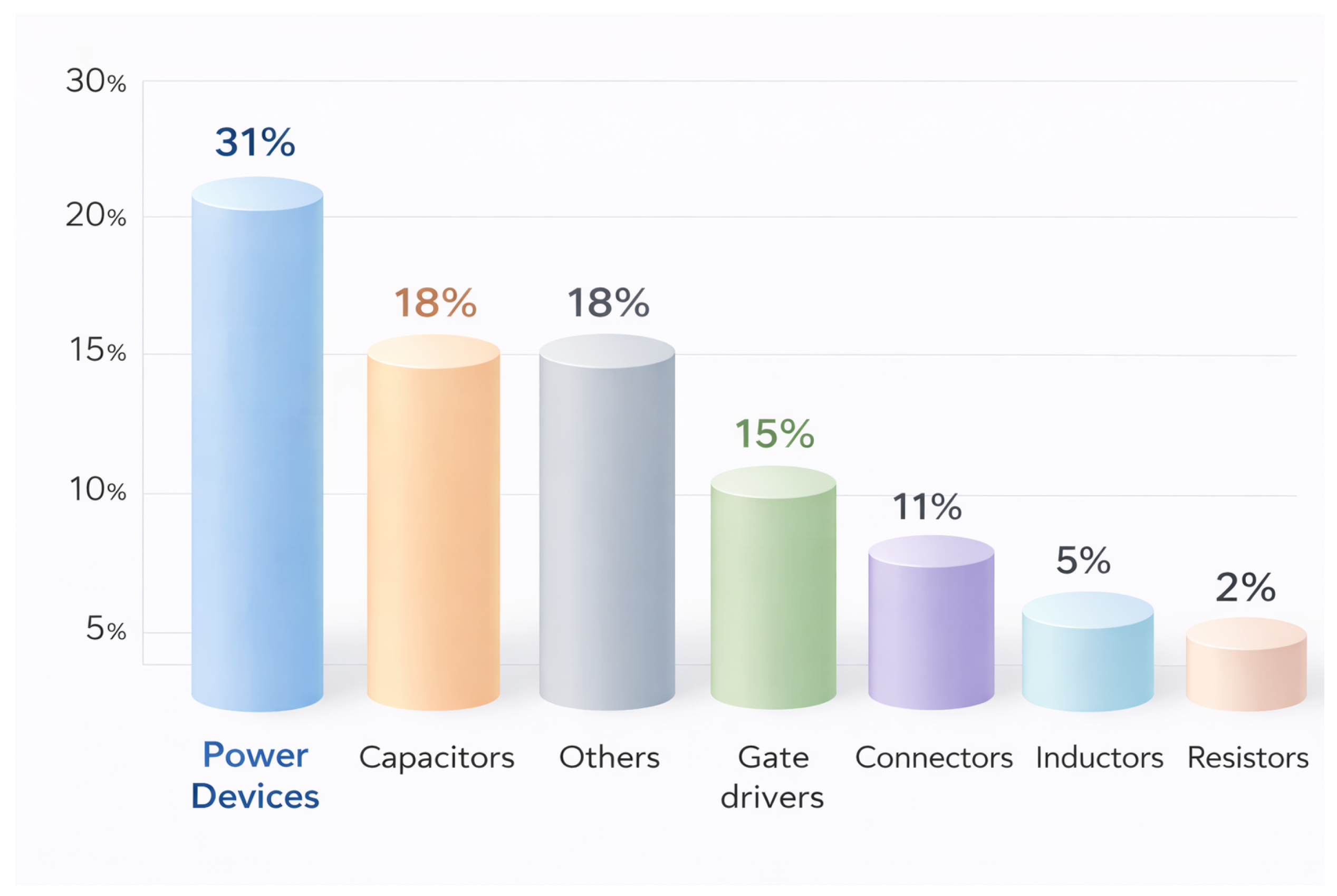
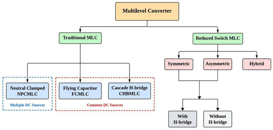
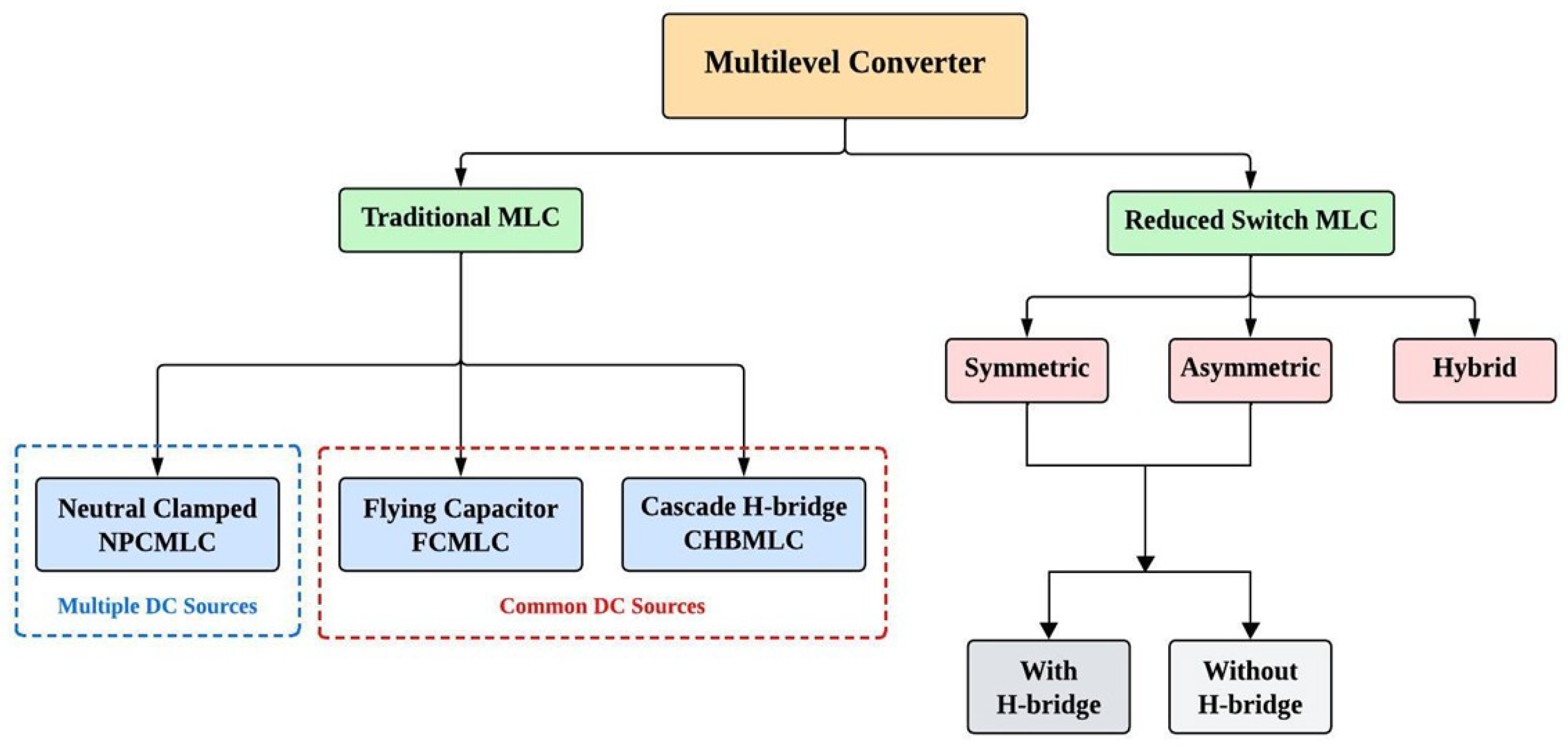
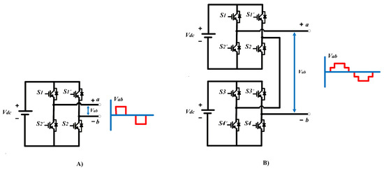
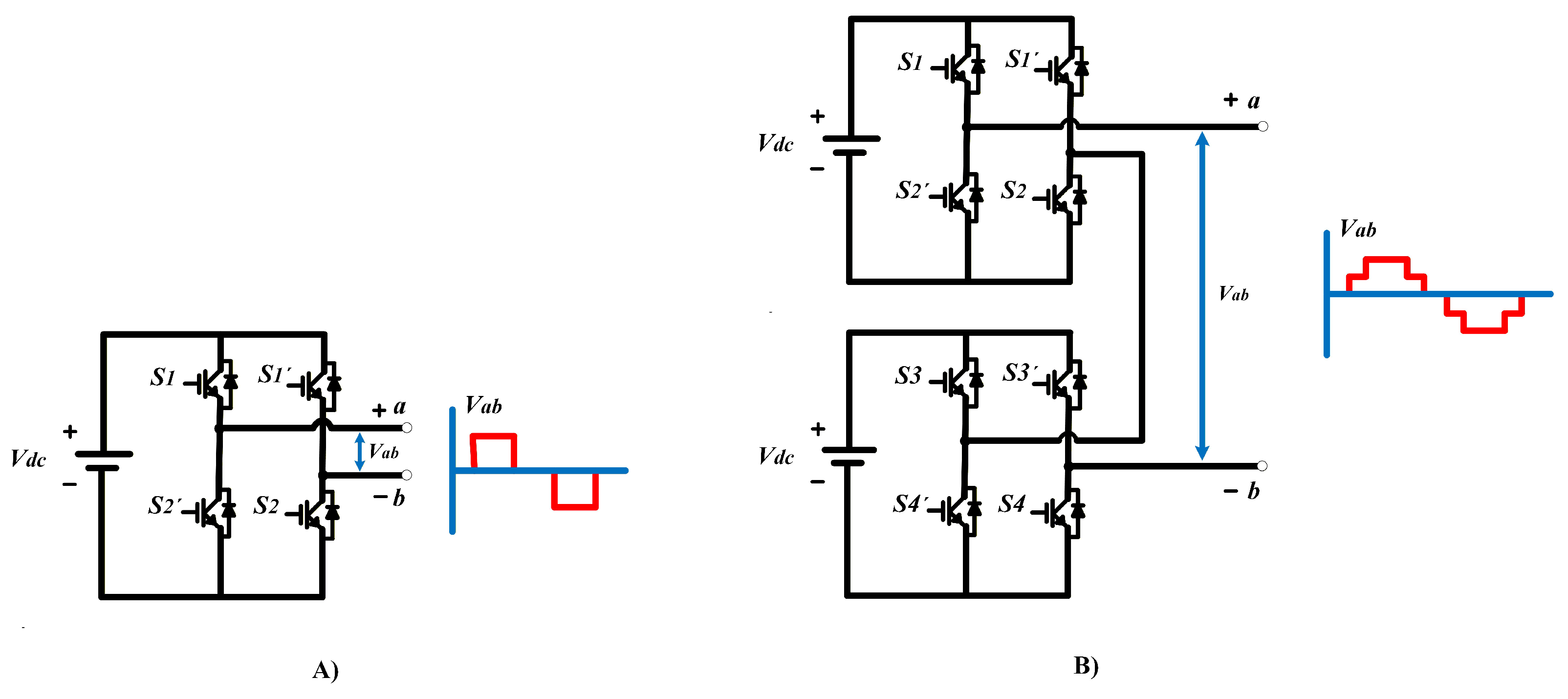
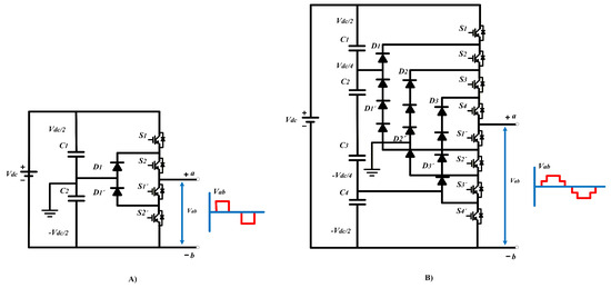
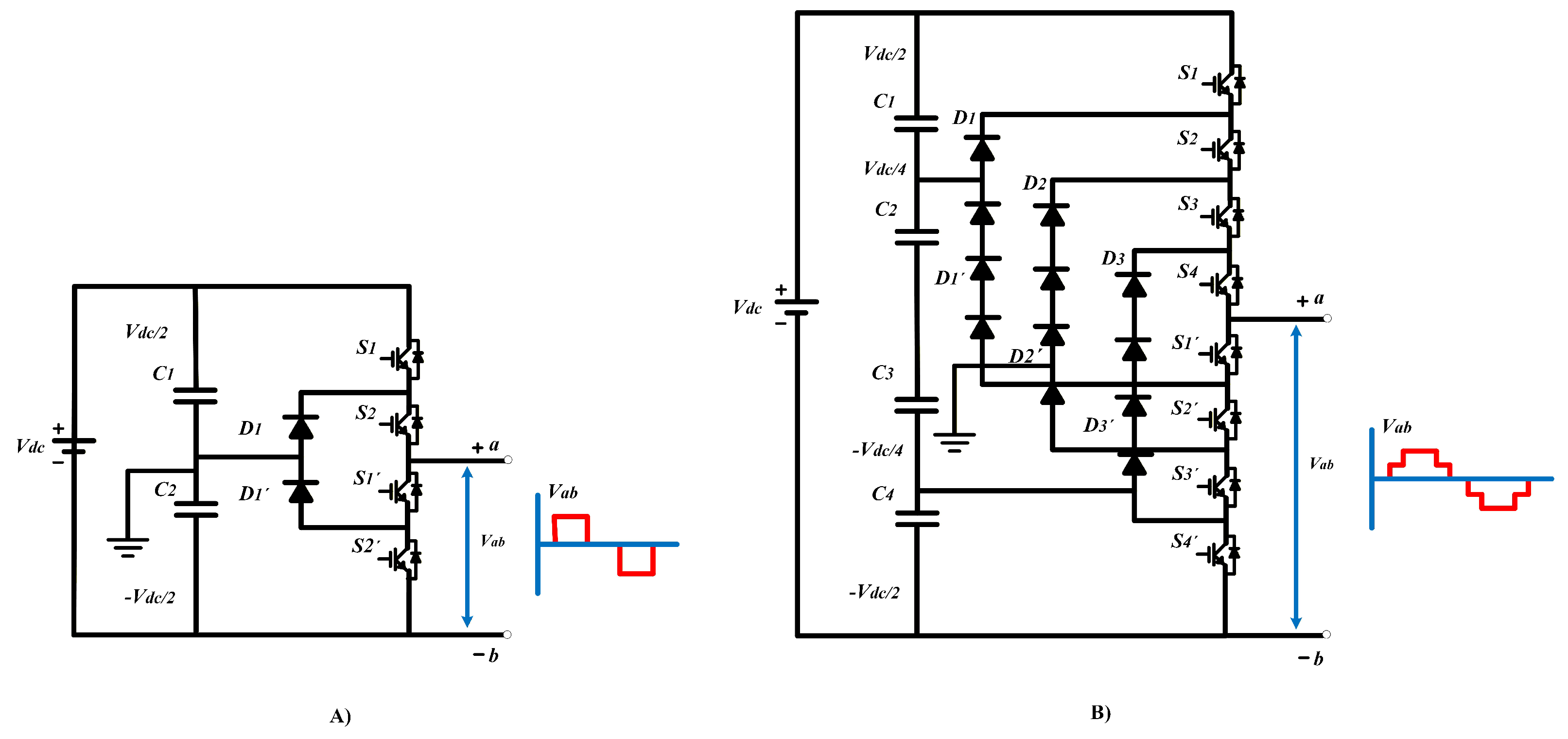
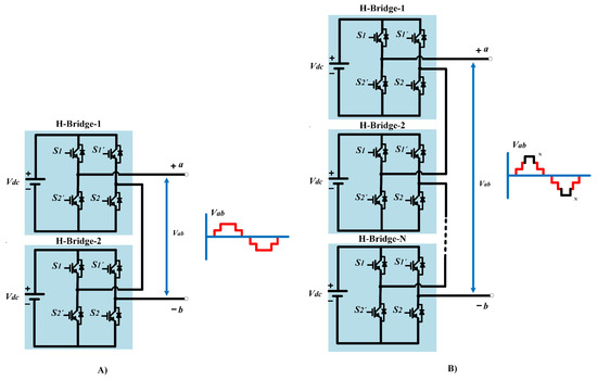
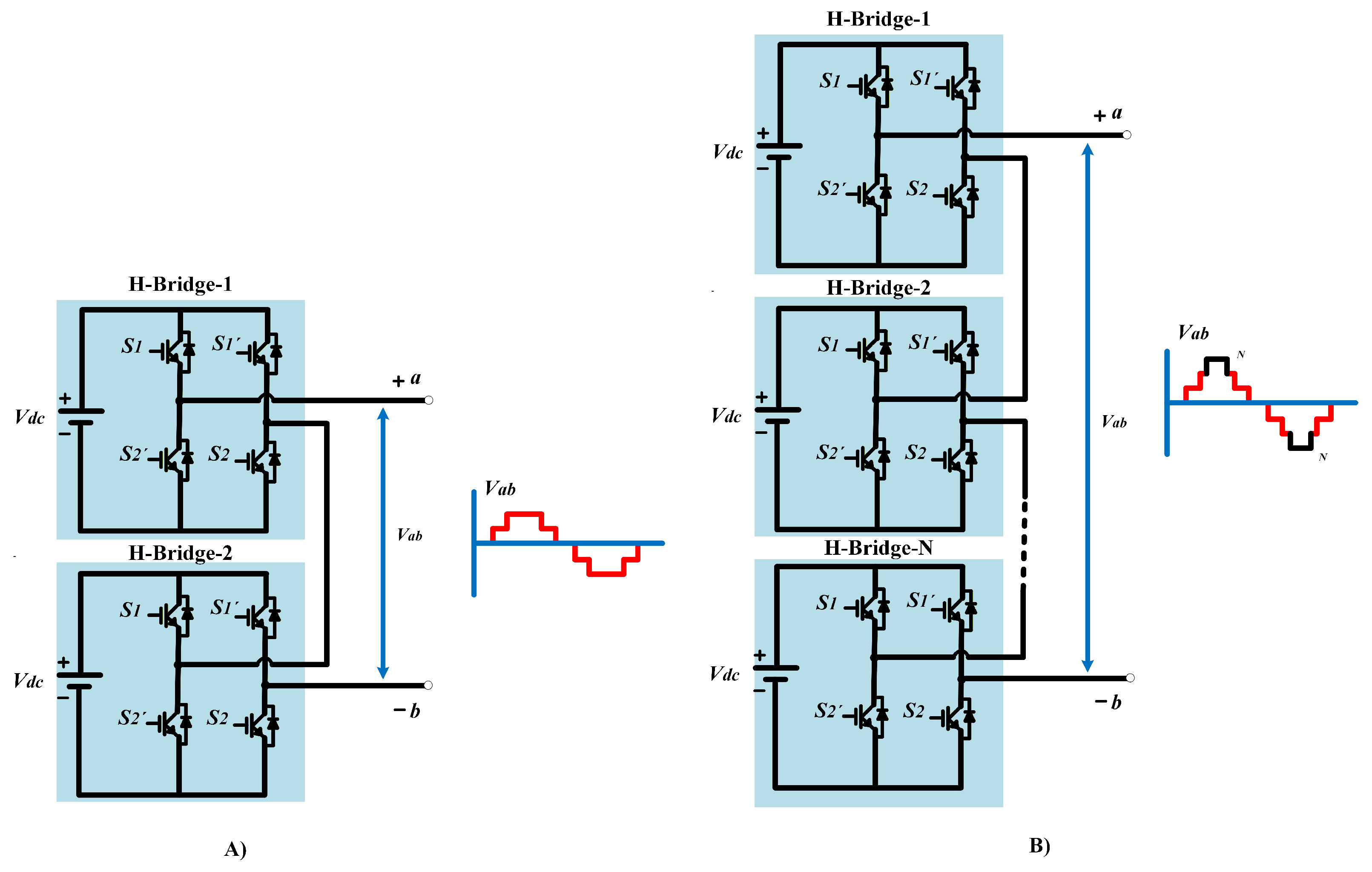
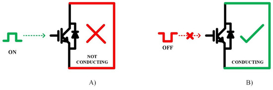
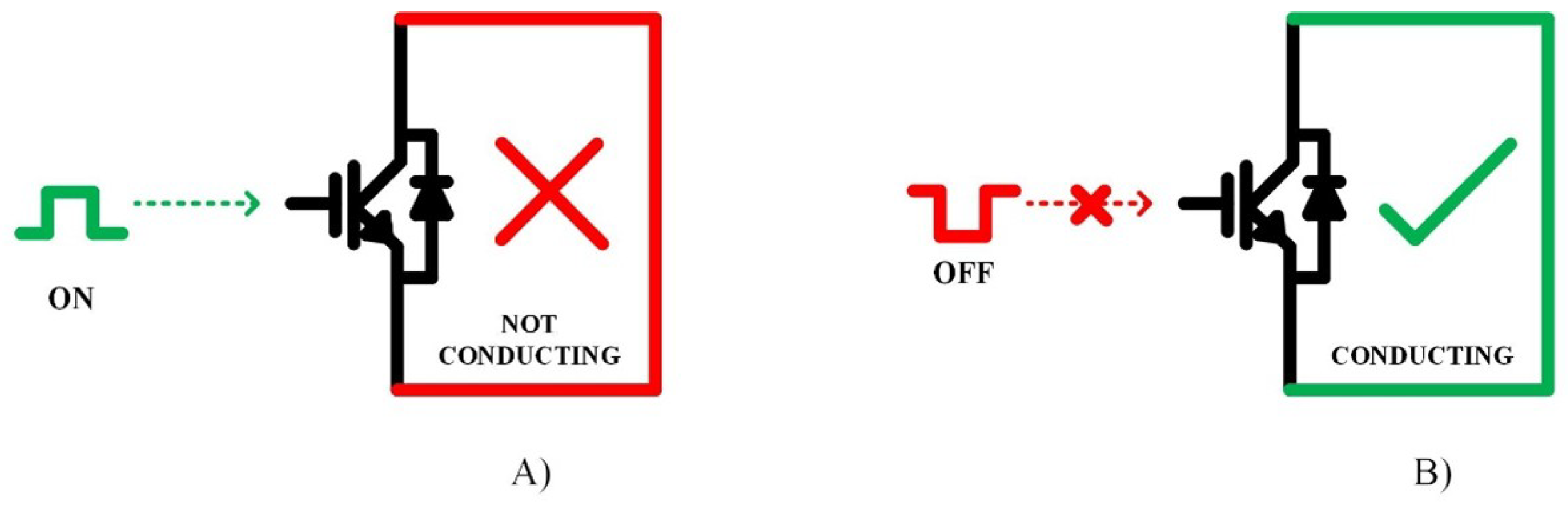
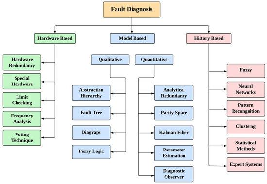
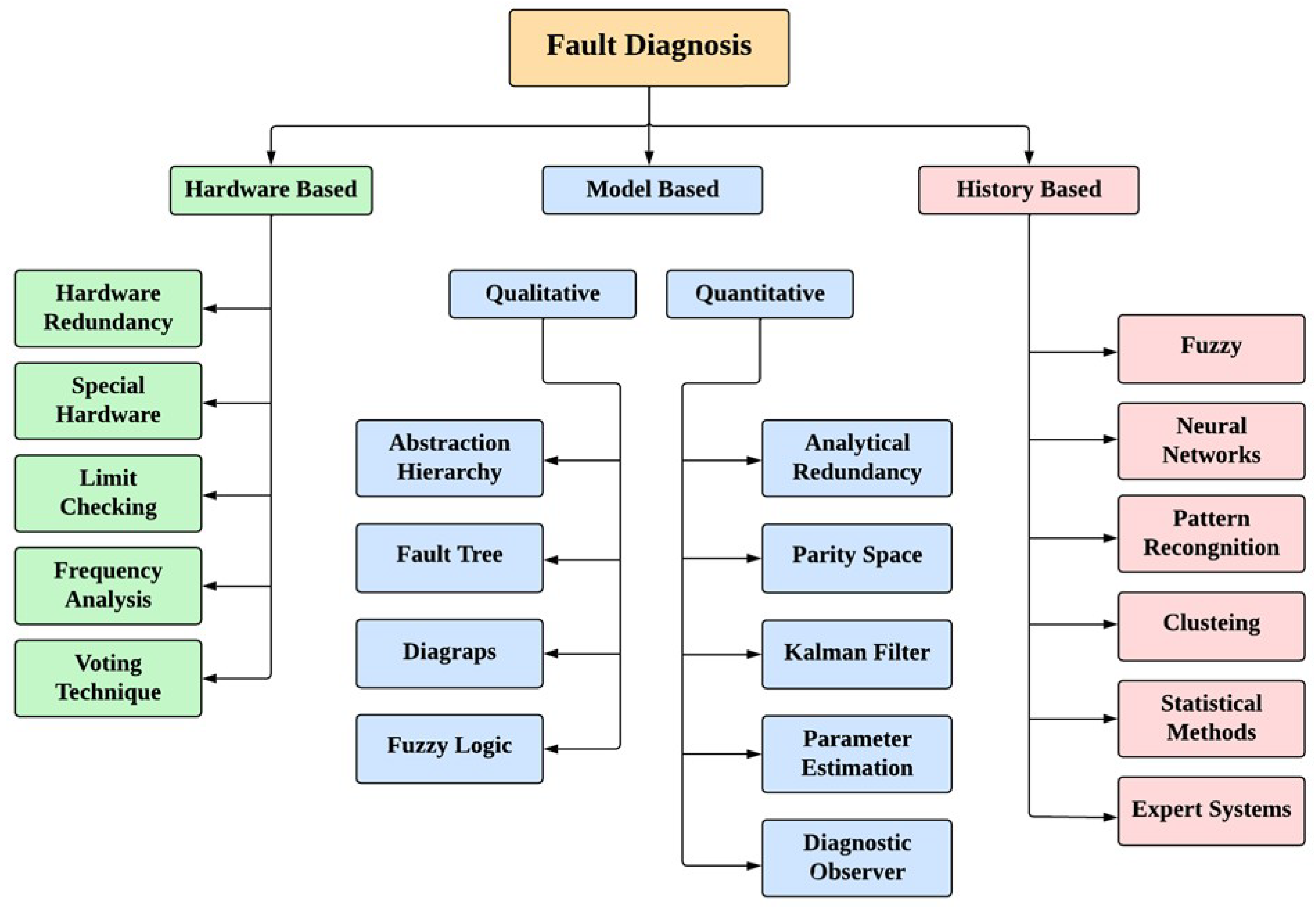
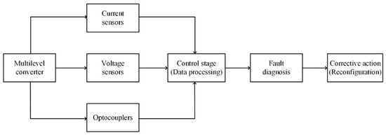
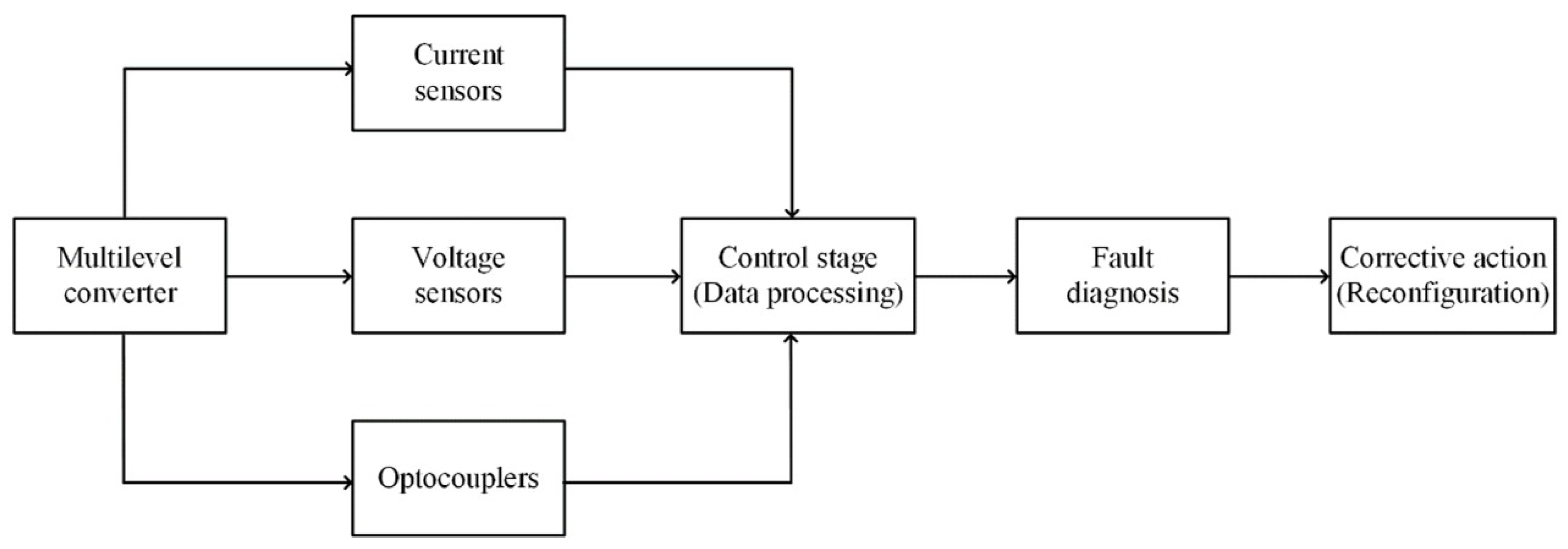
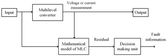
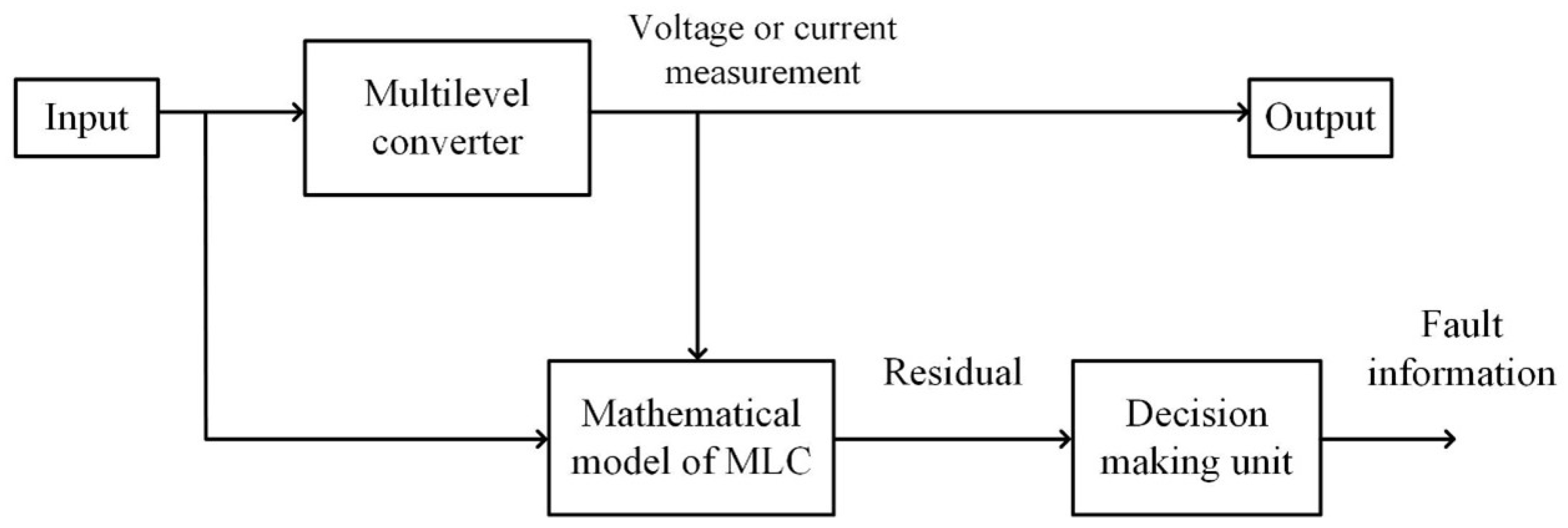
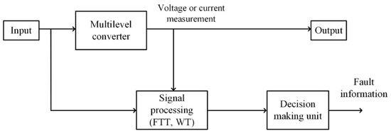
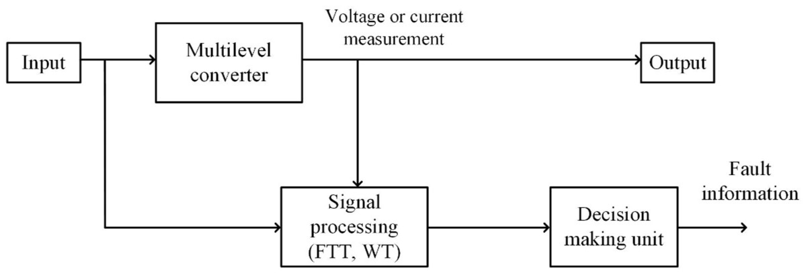

Disclaimer/Publisher’s Note: The statements, opinions and data contained in all publications are solely those of the individual author(s) and contributor(s) and not of MDPI and/or the editor(s). MDPI and/or the editor(s) disclaim responsibility for any injury to people or property resulting from any ideas, methods, instructions or products referred to in the content. |
© 2026 by the authors. Licensee MDPI, Basel, Switzerland. This article is an open access article distributed under the terms and conditions of the Creative Commons Attribution (CC BY) license.