


Abstract
This study proposes a design method based on adjoint shape optimization to enhance the heat transfer efficiency of shell-and-tube heat exchangers in oil and gas transportation systems. The primary focus of this work is the design optimization of shell-and-tube heat exchangers through geometric optimization. By simplifying the complex three-dimensional shell-and-tube heat exchanger into a pseudo-three-dimensional reduced-order model, two-dimensional adjoint shape optimization analyses were conducted under unidirectional symmetry about the x-axis and bidirectional symmetry in the x- and y-axes, respectively. The optimized two-dimensional models exhibited a significant increase in the average outlet temperature. Furthermore, the optimized two-dimensional shapes were extruded and reconstructed into three-dimensional models for validation. The results demonstrate that the average air outlet temperature of the three-dimensional models increased by 5.35 K and 3.07 K compared to the original design. Flow field analysis revealed that the heat transfer was improved, since the optimized pipeline layout enhances flow separation and turbulent mixing, leading to a more uniform temperature distribution. This study validates the effectiveness of the adjoint shape optimization method in improving the performance of shell-and-tube heat exchangers.
1. Introduction
The high pour point and viscosity of petroleum, coupled with the stringent temperature and pressure requirements for natural gas transportation, have driven the industrial sector to adopt shell-and-tube heat exchangers. These exchangers provide high reliability and adaptability, ensuring the safe, stable, and efficient long-distance transportation of petroleum and natural gas. To enhance the economic efficiency and reliability of the entire oil and gas transportation system while reducing carbon emissions, researchers have focused on optimizing the heat transfer efficiency of shell-and-tube heat exchangers. These studies are primarily conducted from an optimization design perspective.
Current research on the optimization design of heat exchangers mainly focuses on three core dimensions: heat transfer tube surface optimization, tube insert optimization, and baffle structure optimization. In terms of heat transfer tube surface optimization, Pethkool et al. [1] conducted an in-depth experimental study on helically corrugated tubes under turbulent conditions. They focused on the effects of pitch ratio and rib height ratio on performance. The results showed that the corrugated structure could significantly enhance fluid disturbance. The heat transfer coefficient increased with the increase in rib height, reaching up to 2.5 times that of smooth tubes, but this was also accompanied by a significant increase in the friction factor. Córcoles-Tendero et al. [2] established a three-dimensional numerical model. Their analysis pointed out that the high-intensity near-wall turbulence induced by corrugation is the core driving force for heat transfer enhancement, and they verified the high consistency between simulation results and experimental data. Gao et al. [3] broke through the limitations of periodic boundary conditions and conducted a full-scale numerical analysis of multi-pass heat exchangers. Based on the field synergy principle, their study quantified that helically corrugated tubes improved the synergy angle between the velocity vector and temperature gradient. This increased the Nusselt number by about 125%, but the pressure drop along the full-scale flow path also increased by about 134%. Besides corrugated tubes, finned tubes, as a classic form of extended surfaces, have also seen refined development. Yang et al. [4] improved the square fin structure and proved that appropriate downward eccentricity design could significantly improve the heat storage rate. Simulations by Amini et al. [5] showed that compared with segmented fins, integral helical fins with small pitch and large height measurements were more significant in improving thermal efficiency. Alimoradi et al. [6] extended the research object to helically coiled tubes. They pointed out that when installing external fins, the multi-parameter collaborative design of the coil diameter, the fin height, and spacing via statistical methods are necessary to minimize system entropy generation. Maghsoudali et al. [7] indicated that simply stacking fins on the shell side would occupy space and hinder fluid flow. This leads to severe channel blockage and fluid bypass effects, which conversely reduces total efficiency. Only a fin layout undergoing system-level topology optimization can overcome blockage while leveraging the advantage of heat transfer enhancement.
Different from tube surface optimization, tube insert optimization utilizes strong swirl flow or secondary flow in the central flow region to enhance heat and mass transfer between the core flow and the wall, thereby improving heat transfer performance. Khoshvaght-Aliabadi et al. [8] proposed a compound enhancement scheme of inserting twisted tapes into elliptical cross-section twisted tubes. Numerical simulations confirmed that the swirl flow generated by the twisted tape superimposed with the rotating flow field induced by the twisted tube wall. This formed a unique double swirl mechanism, which could more thoroughly destroy the thermal boundary layer under laminar conditions. Al-Mosallam et al. [9] extended the research to complex curvature pipes and analyzed flow field characteristics after inserting twisted tapes into spiral coils. They found a complex interaction between the secondary flow induced by the twisted tape and the Dean vortices generated by the centrifugal force of the spiral pipe itself. They pointed out that flow field synergy effects can be maximized only when the swirl direction of the insert precisely matches the helical curvature of the pipe. Additionally, Ayub et al. [10] and Yang et al. [11] innovatively placed twisted tapes, usually used inside tubes, as interstitial fillers between the tubes in the shell side. Experiments confirmed that when processing high-viscosity fluids, this structure reduced shell-side pressure drop by several times by guiding longitudinal flow, although it sacrificed some heat transfer coefficient. Moreover, the intensity of shell-side longitudinal vortices could be precisely controlled by adjusting the tape width and twist ratio.
Baffles are the core heat transfer components of shell-and-tube heat exchangers and not only support the tube bundles but also change the fluid flow path, effectively enhance turbulence, and reduce the thickness of the thermal boundary layer, thereby improving heat transfer efficiency [12]. Baffle structure optimization presents a diversified development trend. According to different fluid-guiding methods, it can be subdivided into three optimization dimensions: transverse flow, helical flow, and longitudinal flow. In the field of transverse flow optimization, traditional segmental baffles have the problem of easily generating dead zones. Mohammadzadeh et al. [13] determined the optimal inclination angle of a baffle to be 25–30° through CFD simulation. The curved baffle design proposed by El-Said et al. [14] utilizes convex/concave streamlined surfaces to guide fluid to flush tube bundles more smoothly transversely, which alleviates the dead zone problem to a certain extent. To further solve the dead zone problem and reduce pressure drop, helical flow optimization has become a mainstream research direction. Studies by Salahuddin et al. [15] and Yang et al. [16] showed that continuous helical baffles could transform shell-side fluid from “Z”-shaped zigzag flow into continuous advancing helical plug flow. This not only eliminated triangular leakage zones but also effectively inhibited fouling risks. The unilateral ladder-type design by Chen et al. [17], the improved fold baffle by Wen et al. [18], and the double-layer continuous helical structure by Yang et al. [19] all improved the Performance Evaluation Criteria (PEC) by constructing more complex helical flow fields. Experiments by Khan et al. [20] on gravitational water vortex heat exchangers also confirmed from a macroscopic perspective that constructing a stable helical flow field is one of the efficient ways to improve heat exchanger effectiveness. Longitudinal flow optimization strengthens mixing by constructing low-resistance flow paths and utilizing local disturbances. Yu et al. [21] introduced longitudinal vortex generators (LVGs) into parallel flow heat exchangers and verified their ability to induce streamwise vortices using the Response Surface Methodology. Yu et al. [22] further proposed polyhedral longitudinal vortex generators (PLVGs). By optimizing parameters such as attack angle through the Taguchi method, they achieved high-efficiency heat transfer with extremely low pressure drop increment. Shaped baffles targeting specific needs have also emerged endlessly. Ambekar et al. [23] found that flower baffles performed best in reducing shell-side pressure drop. Comparative research by El Maakoula et al. [24] showed that trefoil-hole baffles possessed significant advantages in heat transfer enhancement by generating multi-jet flushing against tube walls. Meanwhile, the porous medium baffles introduced by Mohammadi et al. [25] effectively eliminated local hot spots by optimizing porosity through genetic algorithms.
The aforementioned optimization designs often rely on the experience and intuition of designers, which, although capable of improving heat transfer performance to a certain extent, makes it difficult to obtain a global optimal solution. To pursue the maximization of performance and benefits, modern shell-and-tube heat exchanger optimization design often introduces numerical optimization algorithms, guided by an objective function, to inversely derive design variables through multiple iterations, thereby determining the optimal solution. The genetic algorithm (GA) is the most mature method applied in this field. Selbaş et al. [26] and Özçelik [27] utilized genetic algorithms relatively early to conduct economic and thermodynamic optimization of shell-and-tube heat exchangers with the objectives of minimizing heat transfer area and minimizing cost, respectively. Sadeghzadeh et al. [28] further compared the genetic algorithm (GA) to Particle Swarm Optimization (PSO), and the results showed that the GA’s convergence accuracy was slightly better than PSO when seeking the minimum total annual cost. Based on genetic algorithm research, some scholars have introduced novel algorithms with lower cost and better efficiency. Şahin et al. [29] adopted the Artificial Bee Colony (ABC) algorithm to optimize heat exchanger design, proving it had more advantages than the GA and PSO in reducing total cost. Tharakeshwar et al. [30] introduced the Bat Algorithm (BA), which not only obtained a better Pareto front in multi-objective optimization but also required a computation time of only 56% of that of GA. Multi-objective optimization algorithms are often applied to solve the balance problem between heat transfer and pressure drop. Sanaye and Hajabdollahi [31] utilized the NSGA-II algorithm to simultaneously optimize efficiency and total cost, revealing the complex coupling relationship among seven design variables. In addition, Mirzaei et al. [32] combined Constructal Theory with genetic algorithms, and Wang et al. [33] developed an intelligent optimization framework integrating mesh generation for helical coiled tube heat exchangers, both achieving significant improvements in comprehensive performance.
Although the above studies have achieved significant results in determining optimal solutions, the computational cost of traditional gradient algorithms often scales linearly with increases in design variables, making it difficult to deal with complex shape optimization problems. In contrast, the adjoint shape optimization method evaluates the sensitivity of the objective function by solving a set of adjoint equations while solving the primal flow equations. This method can obtain the gradient information of the objective function through a single analysis calculation without considering the number of design parameters. Therefore, a key advantage of the adjoint shape optimization method is that the cost of computing gradients is essentially independent of the number of design variables [34,35,36,37]. Leveraging these advantages, this study integrated a fluid-based adjoint optimization framework into the shape design of shell-and-tube heat exchangers, aiming to improve heat transfer performance. The research idea structure of this paper is as follows: Section 2 introduces the numerical simulation method, focusing on the verification of numerical simulation results against experimental results and grid independence analysis. Section 3 draws on ideas from the literature to simplify the geometric structure of the three-dimensional complex shell-and-tube heat exchanger, converting it into a more manageable two-dimensional planar model to conduct detailed analysis of fluid flow and heat transfer, then extends the two-dimensional optimization problem to three-dimensional space, executing comprehensive three-dimensional adjoint optimization on the real shell-and-tube heat exchanger model.
2. Numerical Simulation Methods
2.1. Governing Equations
Referring to the studies of Song et al. [38] and Patankar et al. [39], fluid flow and heat transfer can be described by the unified partial differential Equation (1):
In this equation, denotes the fluid density (kg/m3), t represents time (s), and indicates the velocity vector (m/s). The symbol serves as a general dependent variable, representing physical quantities such as velocity, concentration, temperature, turbulent kinetic energy, and turbulent dissipation rate in this simulation. Additionally, (m/s2) and are, respectively, defined as the effective diffusion coefficient and the source term corresponding to the variable .
2.2. Model Verification
To verify the reliability of the numerical method employed in this study, the experimental data from Liu et al. [40] were selected as a benchmark for validation, with specific geometric parameters adopted directly from the original literature.
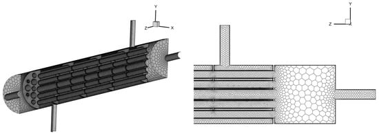
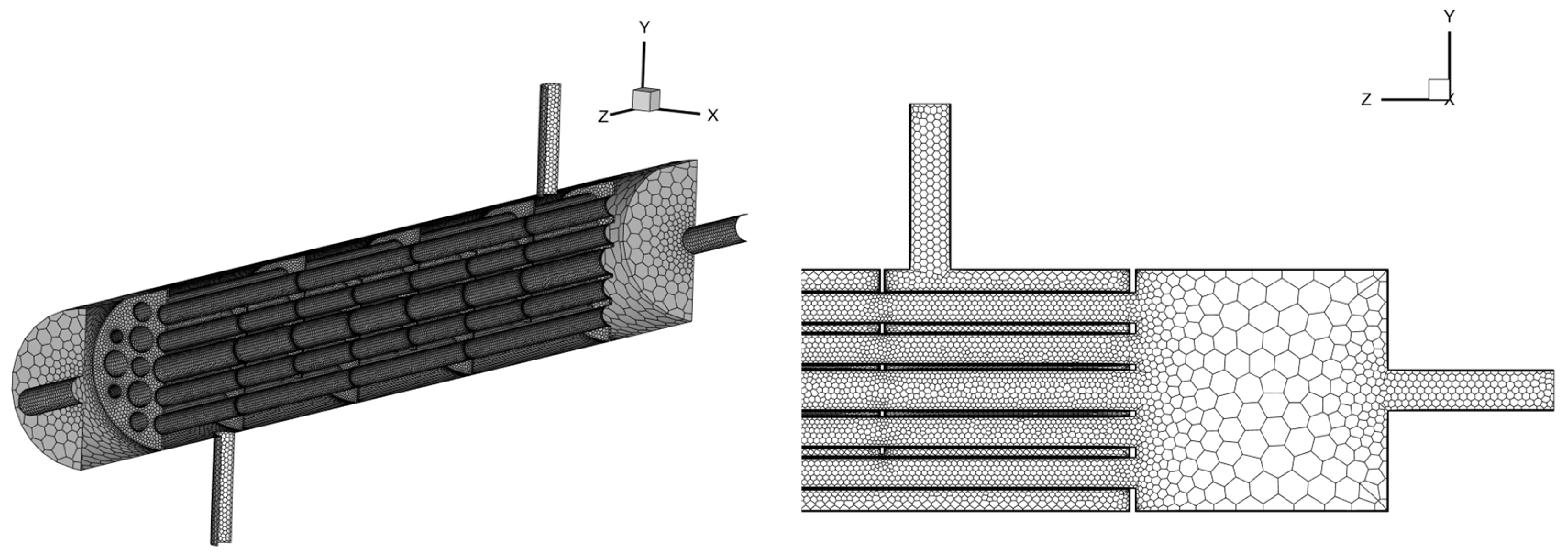
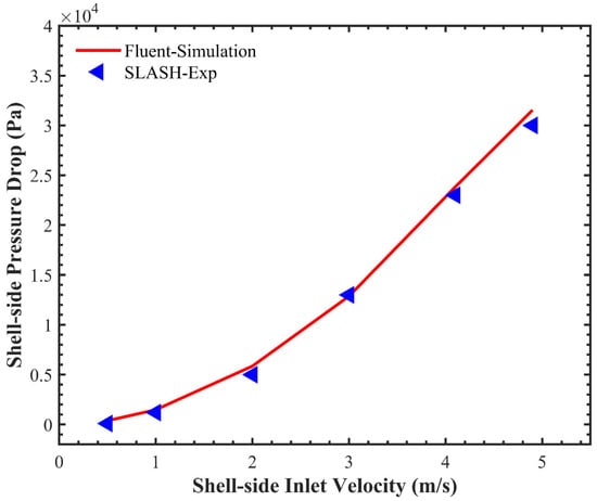
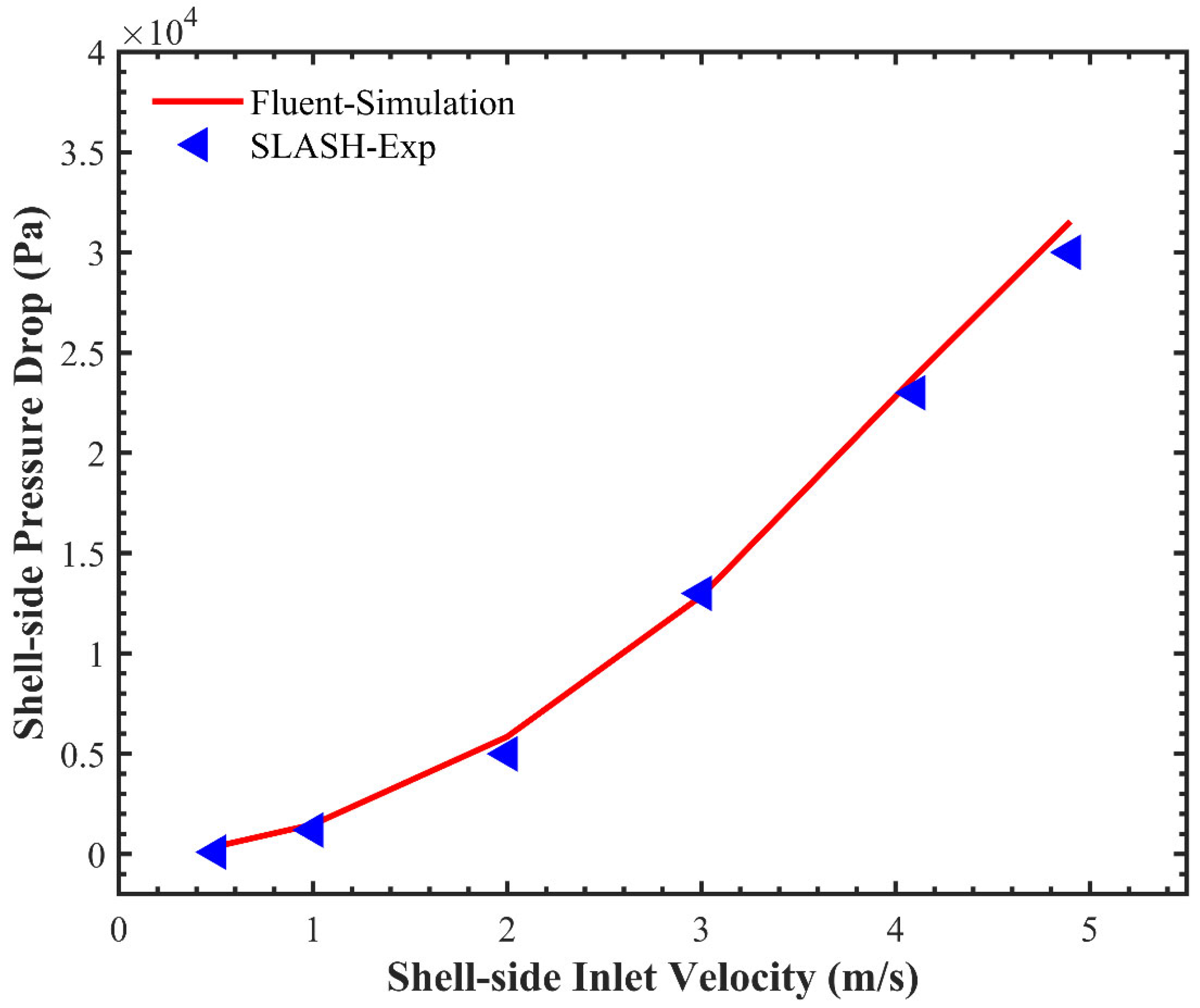
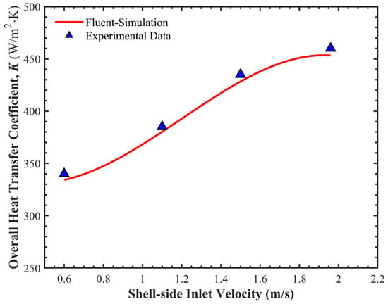
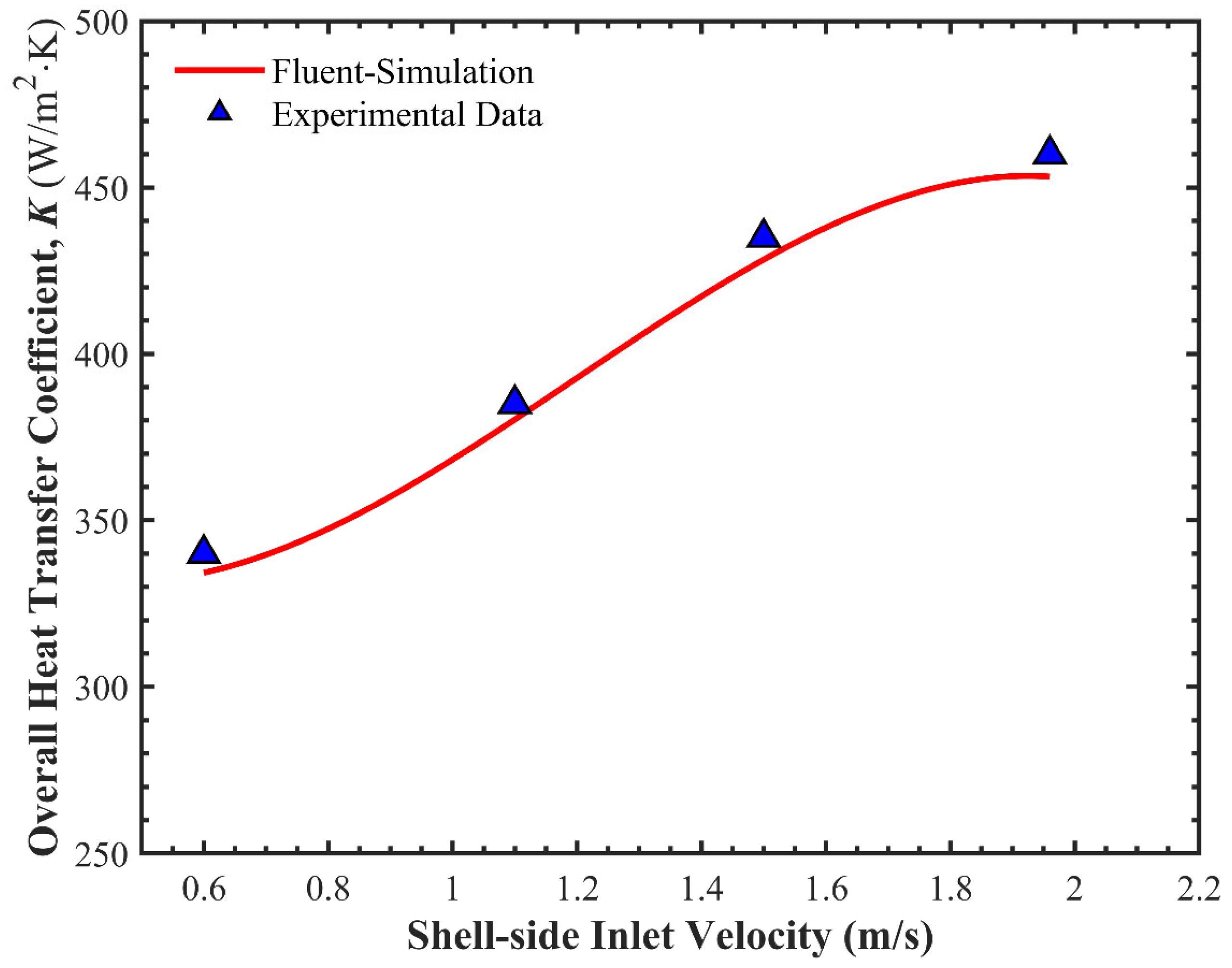
A numerical model with the exact same geometry as the experiment was established using the computational fluid dynamics software ANSYS Fluent 2024 R1. Figure 1 illustrates the polyhedral mesh model generated based on the experimental geometry, consisting of 1,623,532 cells. In this validation case, the standard model was employed, which is consistent with the subsequent simulations in this study. Figure 2 and Figure 3 present a comparison between the present numerical results and the experimental measurements.
Figure 1.
Schematic of the computational mesh used for experimental validation.
Figure 2.
Comparison of shell-side pressure drop between Fluent simulation results and experimental data.
Figure 3.
Comparison of overall heat transfer coefficient between Fluent simulation results and experimental data.
As illustrated, the simulation results for both shell-side pressure drop and heat transfer efficiency show good agreement with the experimental data in terms of both trend and magnitude. Based on these results, it can be concluded that the established numerical model is capable of accurately predicting heat transfer and pressure drop characteristics.
2.3. Geometric Model
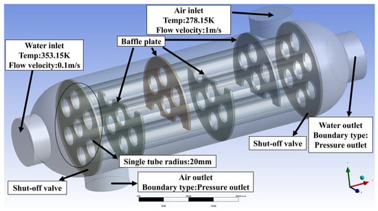
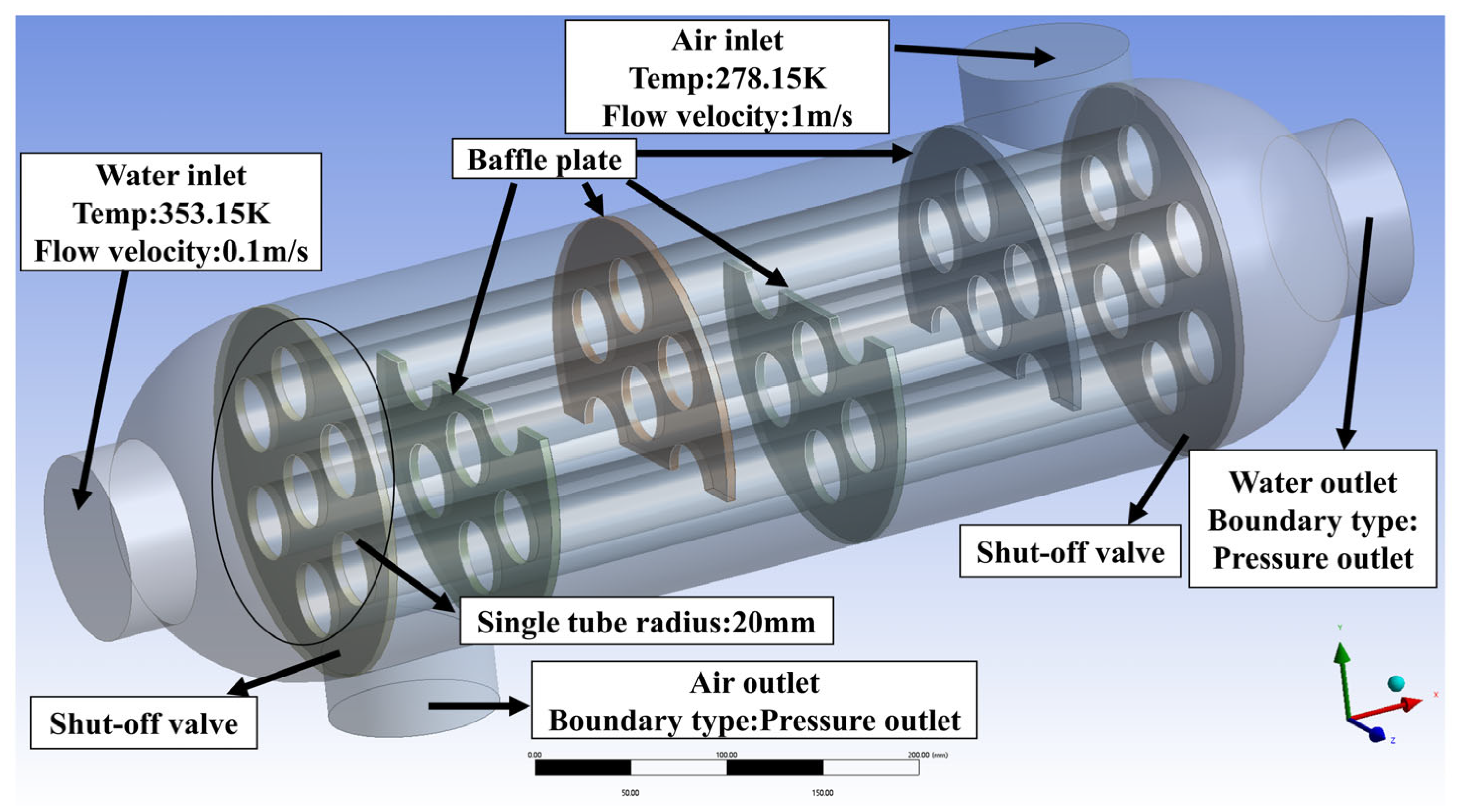
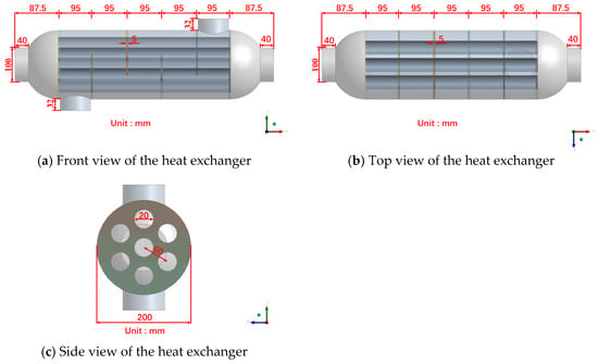
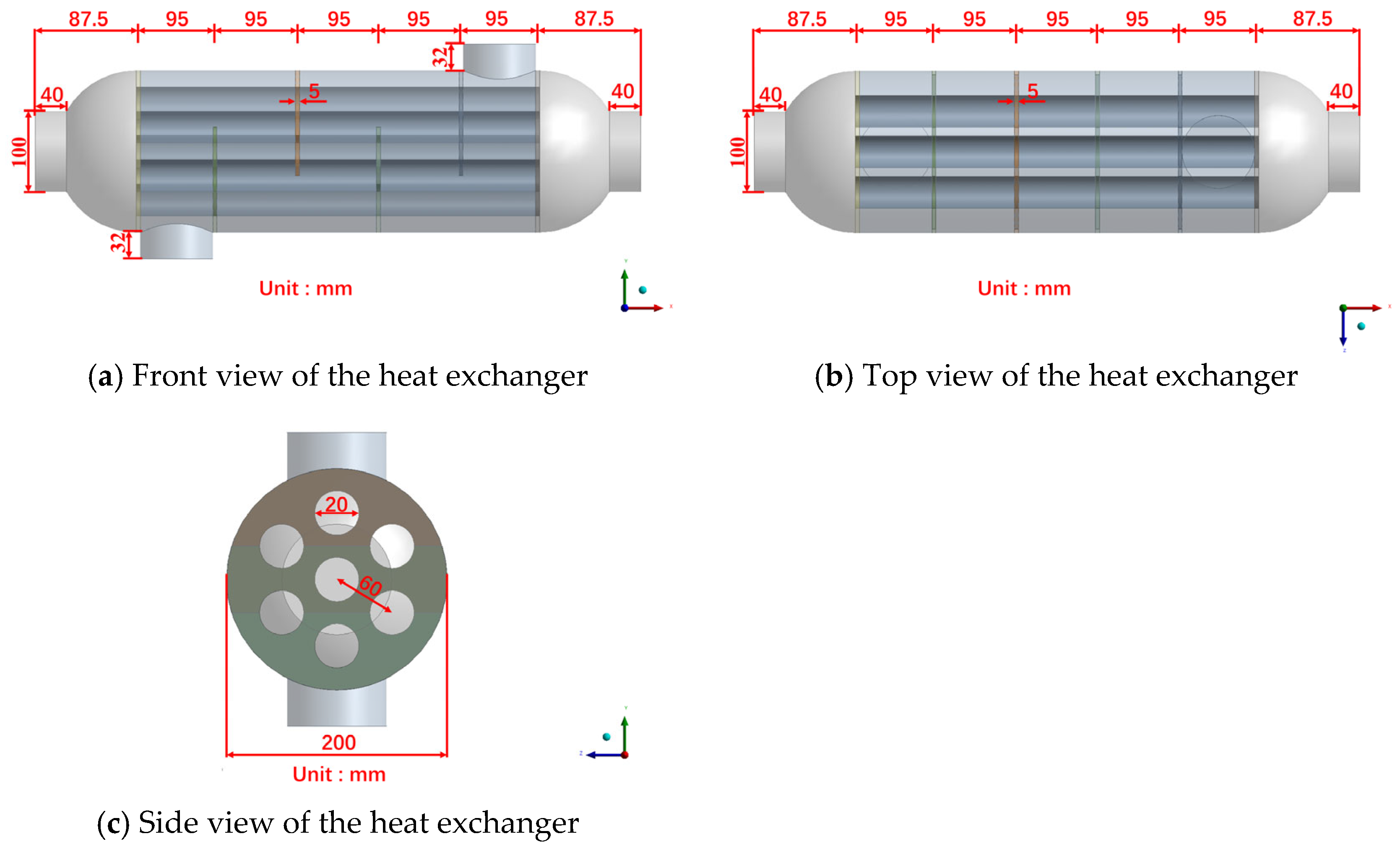
Figure 4 and Figure 5 illustrates the three-dimensional geometric model of the shell-and-tube heat exchanger, highlighting the fluid inlets and outlets, velocity vectors, and structural details. The flow paths of the two working fluids are depicted, with one fluid flowing inside the tubes (tube-side) and the other flowing within the shell (shell-side), exchanging heat through the tube walls.
Figure 4.
Geometric model and boundary conditions.
Figure 5.
Geometric dimensions of the geometric model.
To maximize heat transfer efficiency, a typical counter-current flow configuration is adopted. The boundary conditions are assigned as follows: at the tube-side inlet, the water temperature is set to 353.15 K with a velocity of 0.1 m/s, and at the shell-side inlet, the air temperature is set to 278.15 K with a velocity of 1 m/s. Geometrically, the heat exchanger consists of 7 parallel tubes with a radius of 20 mm, enclosed by a shell with an inner diameter of 100 mm. This configuration facilitates efficient thermal energy transfer between the two fluids under the specified temperature and velocity conditions.
2.4. Grid Independence Verification
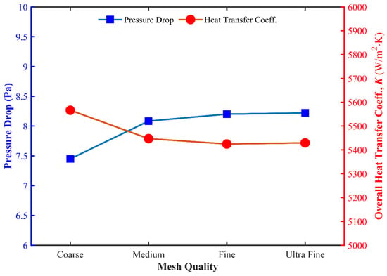
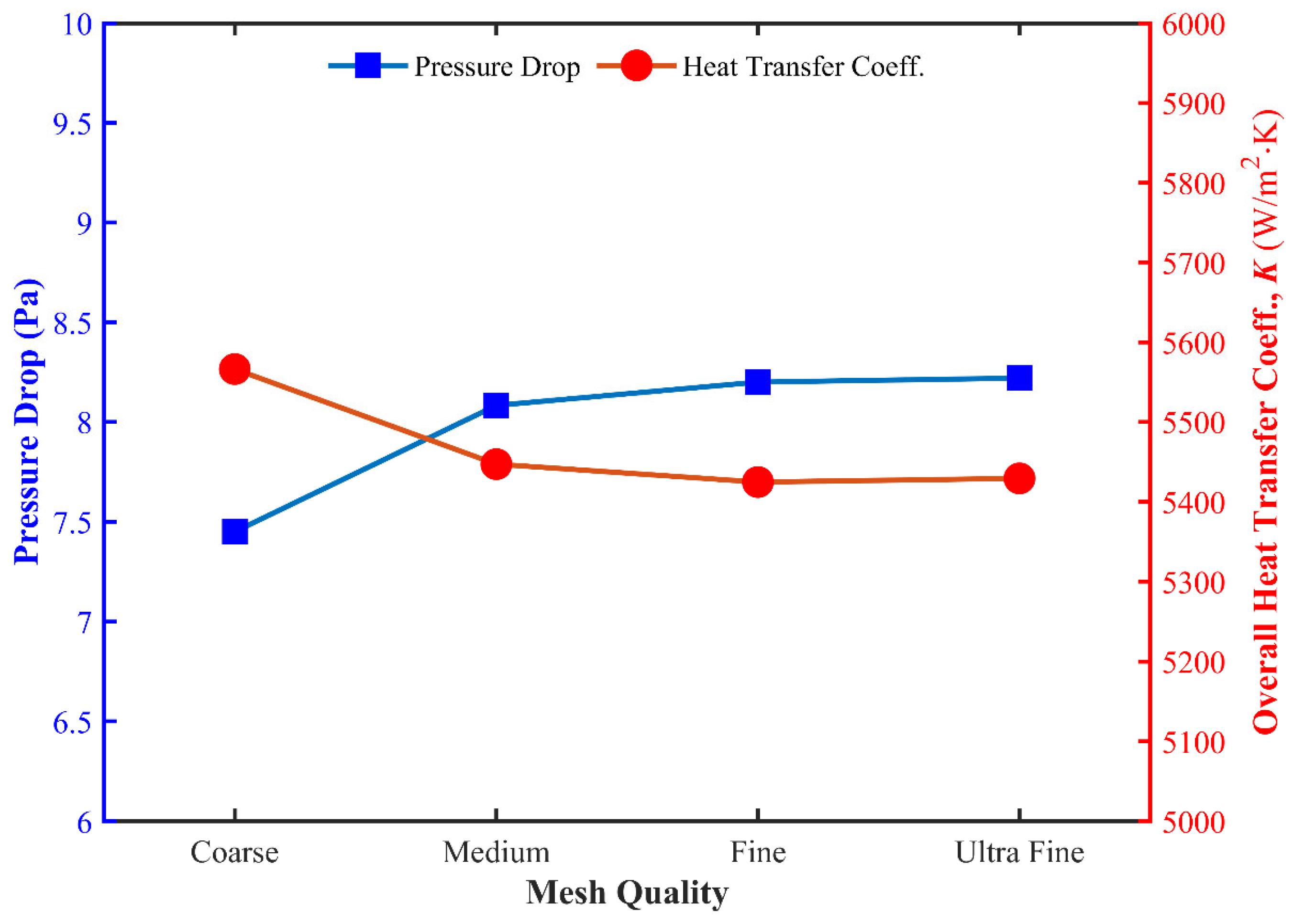
To eliminate the influence of grid number on the numerical calculation results, for this paper, we constructed four sets of grids with different densities to conduct a convergence analysis. The total numbers of cells for these four sets of grids were 112,286 (Coarse), 180,016 (Medium), 256,398 (Fine), and 434,626 (Ultra-fine), respectively. Figure 6 illustrates the variation curves of the air domain pressure drop and the overall heat transfer coefficient of the heat exchanger with respect to the grid number.
Figure 6.
Variation in air-side pressure drop and overall heat transfer coefficient with grid number.
The results indicate that under the Coarse grid, the calculation results show significant deviations from other groups, suggesting that the low-density grid is difficult to use to capture the detailed characteristics of the flow field, whereas when the grid is refined to the Fine level, the calculation results tend to be stable. The values obtained from the Fine grid and the Ultra-fine grid are in high agreement with extremely small relative errors, satisfying the requirements of grid independence. Considering both computational accuracy and the consumption of computational resources, for this paper, we finally selected the Fine grid (256,398) as the computational model for subsequent research.
2.5. Analysis of Heat Exchange Results Before Optimization
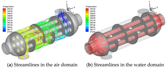
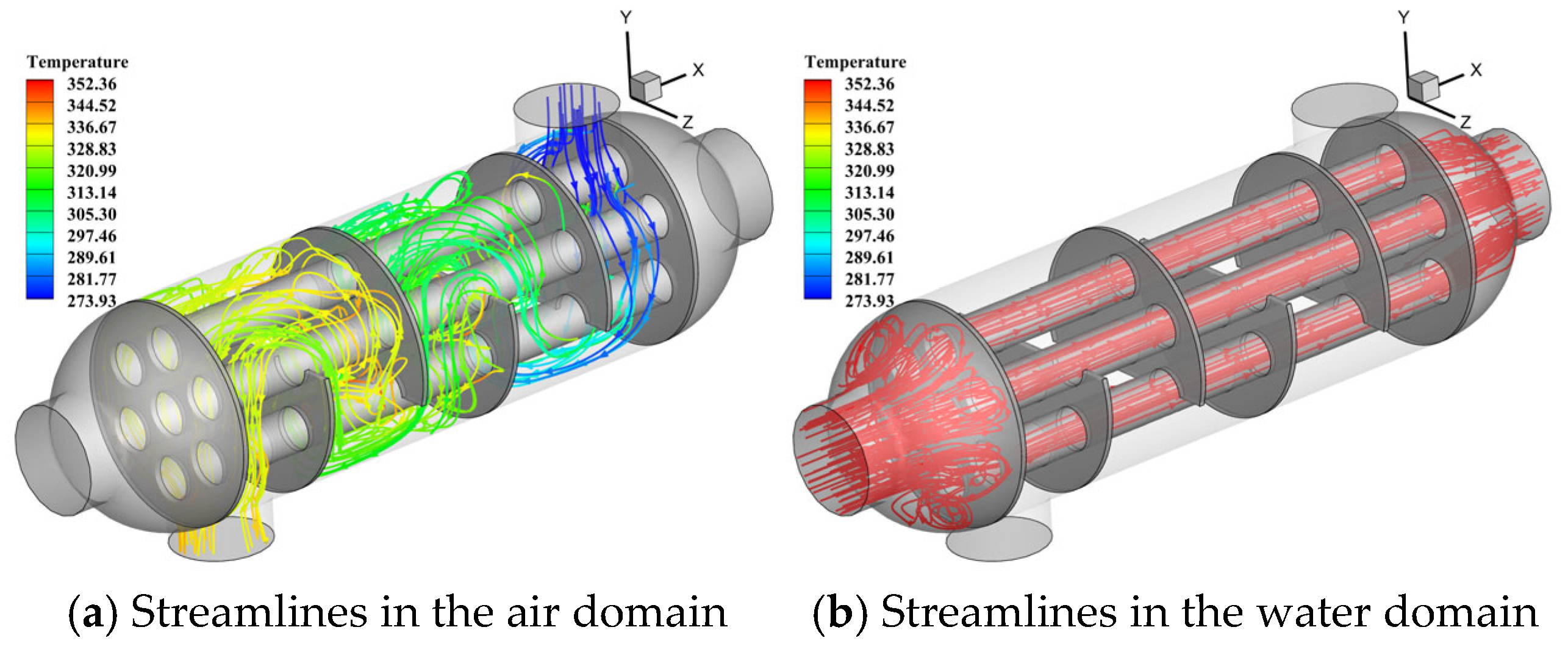
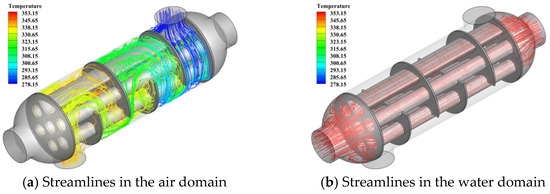
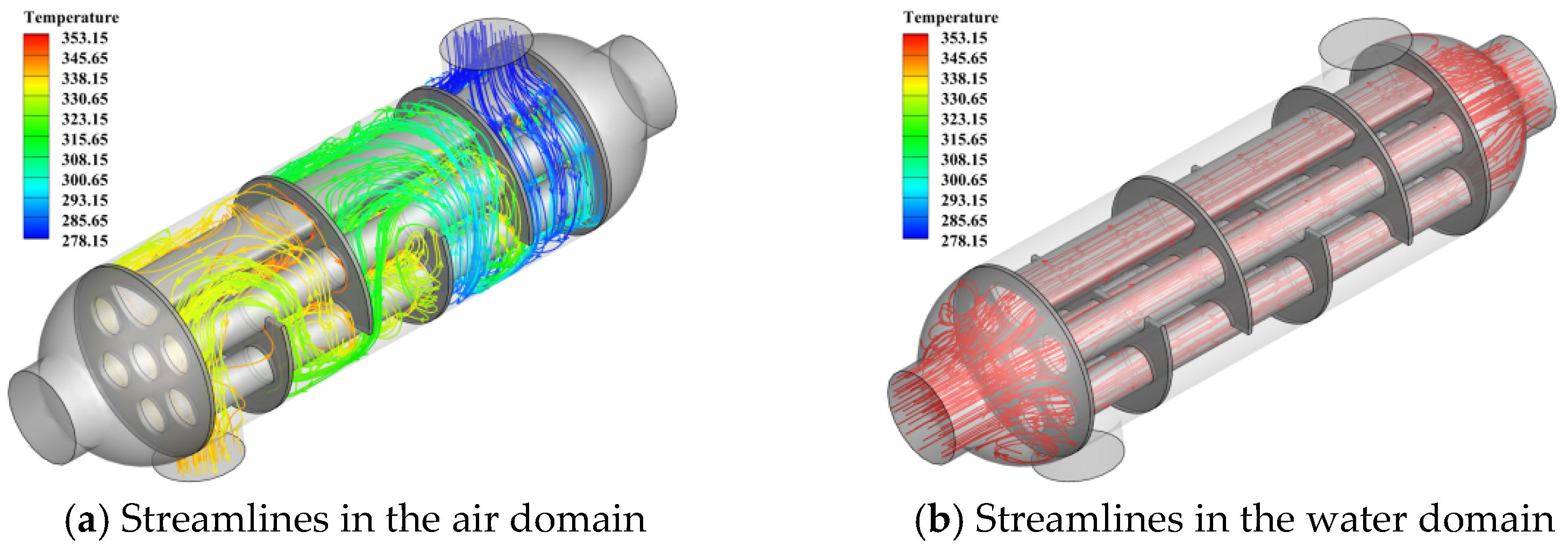
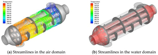
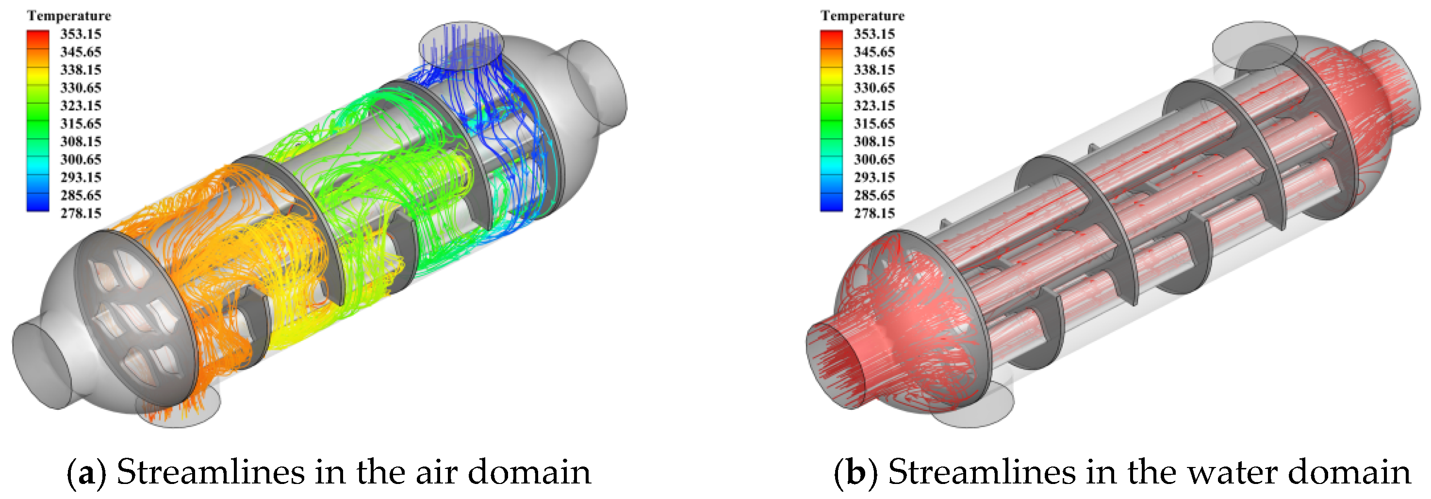
Figure 7 illustrates the spatial temperature streamline distributions within the air and water domains. The colors of the streamlines correspond to the temperature gradient, ranging from low (blue) to high (red). Specifically Figure 7a depicts the airflow path through the tube bundle region. It can be observed that the air temperature undergoes significant changes as it flows past the baffles.
Figure 7.
Spatial temperature streamline distribution of the air and water domains in the original flow field.
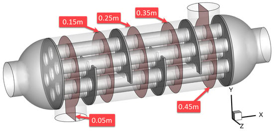
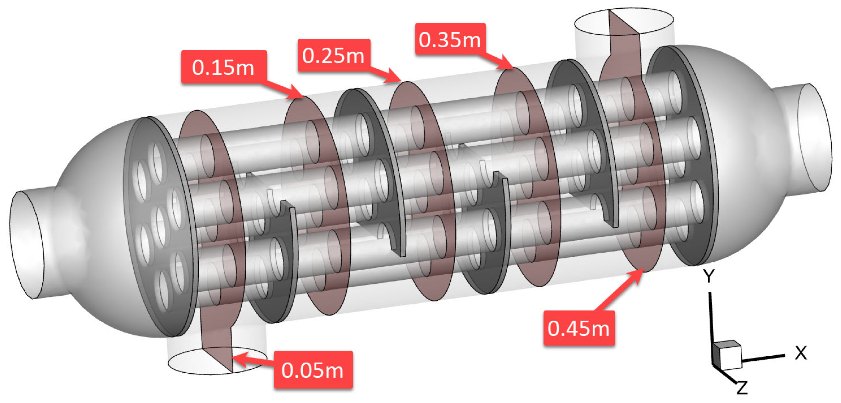
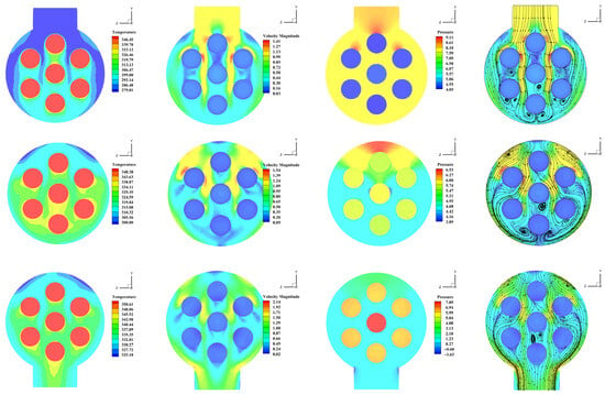
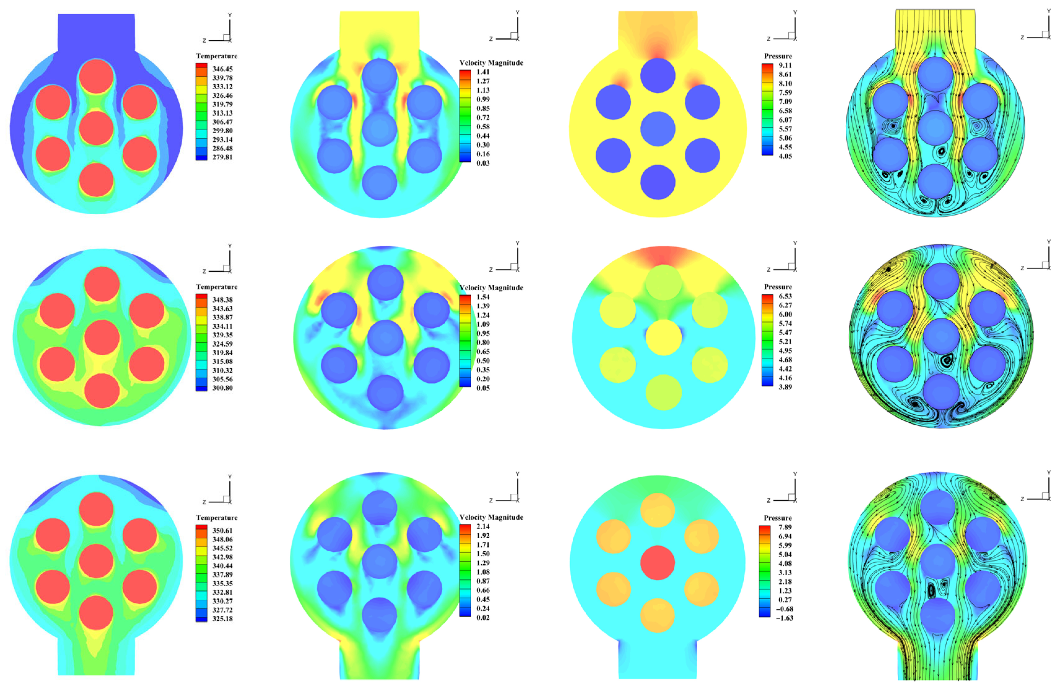
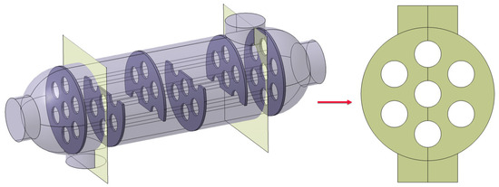
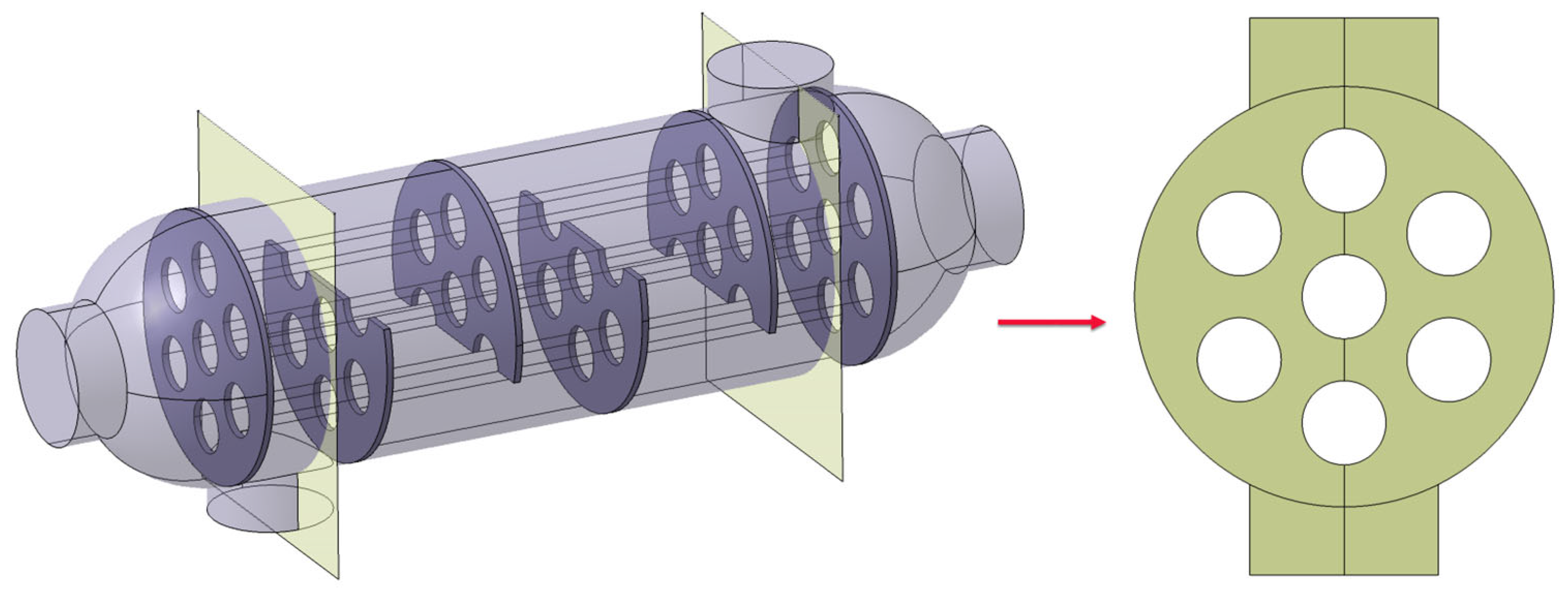
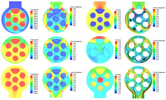
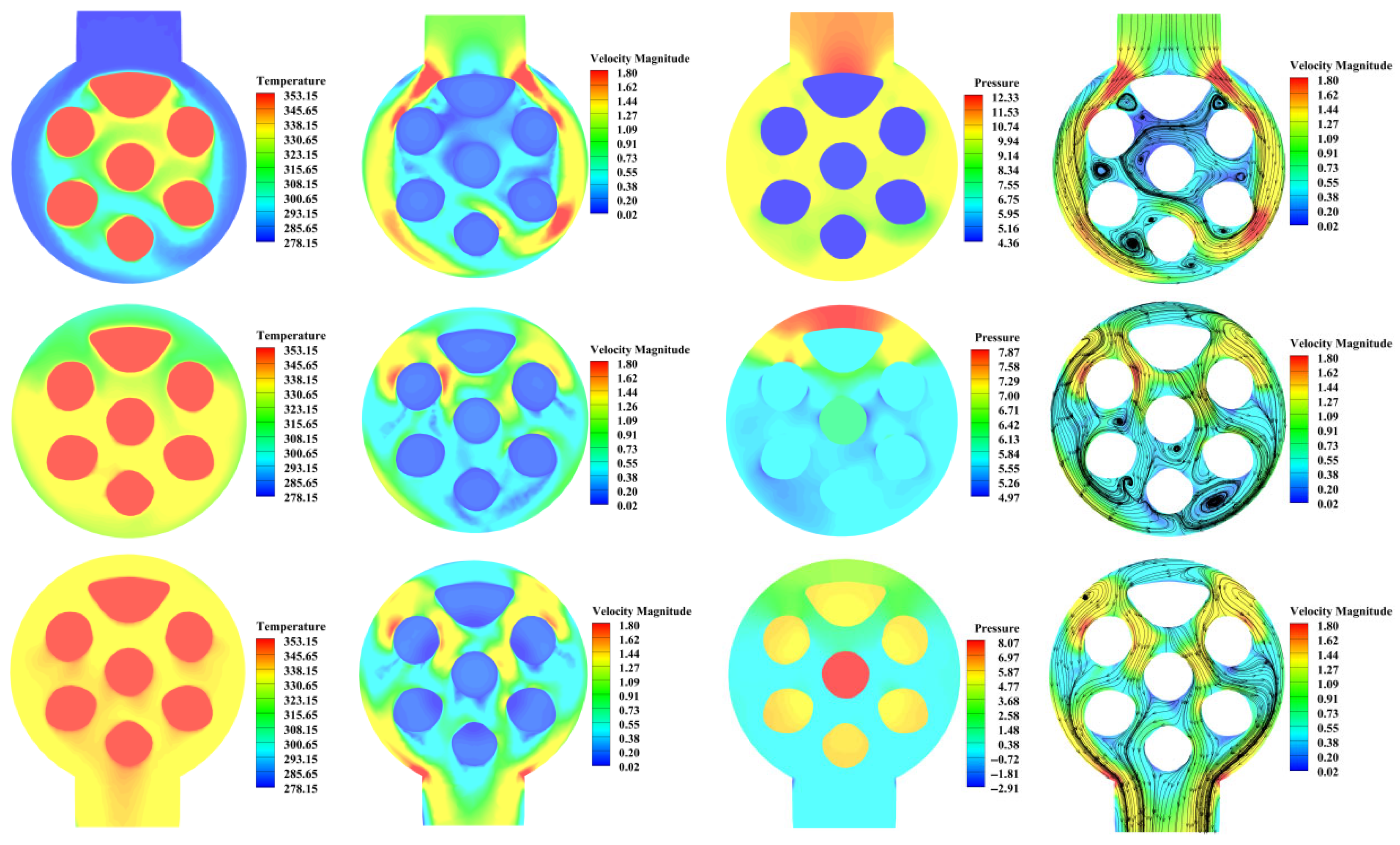
Figure 8 shows the cross-sectional position of the selected shell-and-tube heat exchanger. As shown in Figure 9, cross-sectional analysis at the inlet, midspan, and outlet reveals that air temperature rises along the flow path, reaching an average of 335.65 K at the outlet. While the inlet exhibits significant non-uniformity, baffle-induced disturbances effectively homogenize both temperature and velocity distributions downstream. Pressure decreases due to hydraulic resistance, while peak velocity positions shift continuously. Streamlines indicate complex vortex structures and flow reversals, highlighting the significant impact of the tube bundle geometry on flow and heat transfer characteristics.
Figure 8.
Cross-sectional position of the shell-and-tube heat exchanger.
Figure 9.
Contours of temperature, velocity, pressure, and streamlines at inlet, midspan, and outlet cross-sections for the initial design.
3. Results
3.1. Theory of Adjoint Optimization Method
The discrete adjoint equations, which form the theoretical basis for the adjoint method, were derived by differentiating the discrete flow equations. The gradient vector of the objective function was given by
The term in parentheses in Equation (2) represents the gradient of the fitness function with respect to the entire mesh point set, X; i.e., the gradient when ; is a purely geometric sensitivity term, indicating the mesh disturbance rate once the design parameters are moved from their original positions. In practice, during the design process, the parameter set, , should undergo displacement iteration based on the given search direction (i.e., the gradient), and the resulting geometric changes, in turn, affect the topology of the mesh.
To clearly illustrate the physical quantities during optimization, we converted the matrix notation into a component-wise variational form for detailed derivation. The discrete adjoint equation after eliminating the disturbance of the perturbations can be written as
To ensure the accuracy and stability of gradient calculations, the Green–Gauss Cell-Based scheme was employed for the gradient reconstruction of the adjoint equations. For the present implementation, a preconditioned iterative scheme, based on pseudo-time marching, was adopted to solve the adjoint system. The equations that define the advancement process can be written as
where is a local time-step size based on the local flow conditions and is a user-specified CFL number. The matrix, , is a simplified form of the Jacobian system that is amenable to solution using the AMG linear solver, which is the workhorse of the conventional flow solver. The preconditioning matrix, , is a diagonal matrix. Artificial compressibility was introduced on the adjoint continuity equation to aid in the relaxation of the adjoint pressure field.
The correction, , was under-relaxed and added to the adjoint solution, , and the process repeated until the right-hand side was adequately small.
Adjoint sensitivity data can be used to guide how to modify a system in order to improve the performance. Denote the sensitivity of the cost with respect to shape by
where is the coordinate of the node in the mesh. Here, is a notation for the subset of the control variables, , for the system that correspond to mesh node positions. Then an adjustment,
will provide the maximum adjustment to for the given norm of , where is an arbitrary scaling factor. Note that can be picked to be positive or negative depending upon whether is to be increased or decreased, respectively. This is essentially a statement of the method of steepest descent.
Furthermore, the change is estimated to the first order to be
Surface Representation:
The NURBS curve (vector ) enables the representation of geometric surfaces through a synthesized algebraic relation expressed as
u, w, and P represent the node sequence, weights, and control points of the parameter curve, respectively. In this work, only the control points are considered as design parameters, i.e., ; additionally, it is assumed that the remaining parameters would remain unchanged throughout the optimization process, so Equation (8) was significantly simplified, and the sensitivity can be directly derived.
Mesh Deformation:
The mesh deformation method based on radial basis functions (RBFs) allows for the independent displacement of each mesh node without needing the mesh connectivity. RBFs approximate the displacement of a mesh point, sss, through a weighted sum of basis functions:
Here, is the surface point with known displacement, p is a linear polynomial that ensures the uniqueness of the solution, is the total number of surface points, and is a given basis function dependent on the Euclidean distance, .
3.2. Simplified Two-Dimensional Model
Researchers investigating the optimization of the shell-and-tube heat exchanger tube layout have found that the process requires substantial computational resources and time. To address this, this study adopts the simplification method proposed by Haertel et al. [41]. A pseudo-three-dimensional, dimensionally reduced model was constructed, preserving the air inlet and outlet while simplifying the water tubes to circular apertures, as shown in Figure 10.
Figure 10.
Simplification of the three-dimensional heat exchanger into a two-dimensional shape optimization problem.
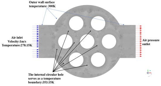
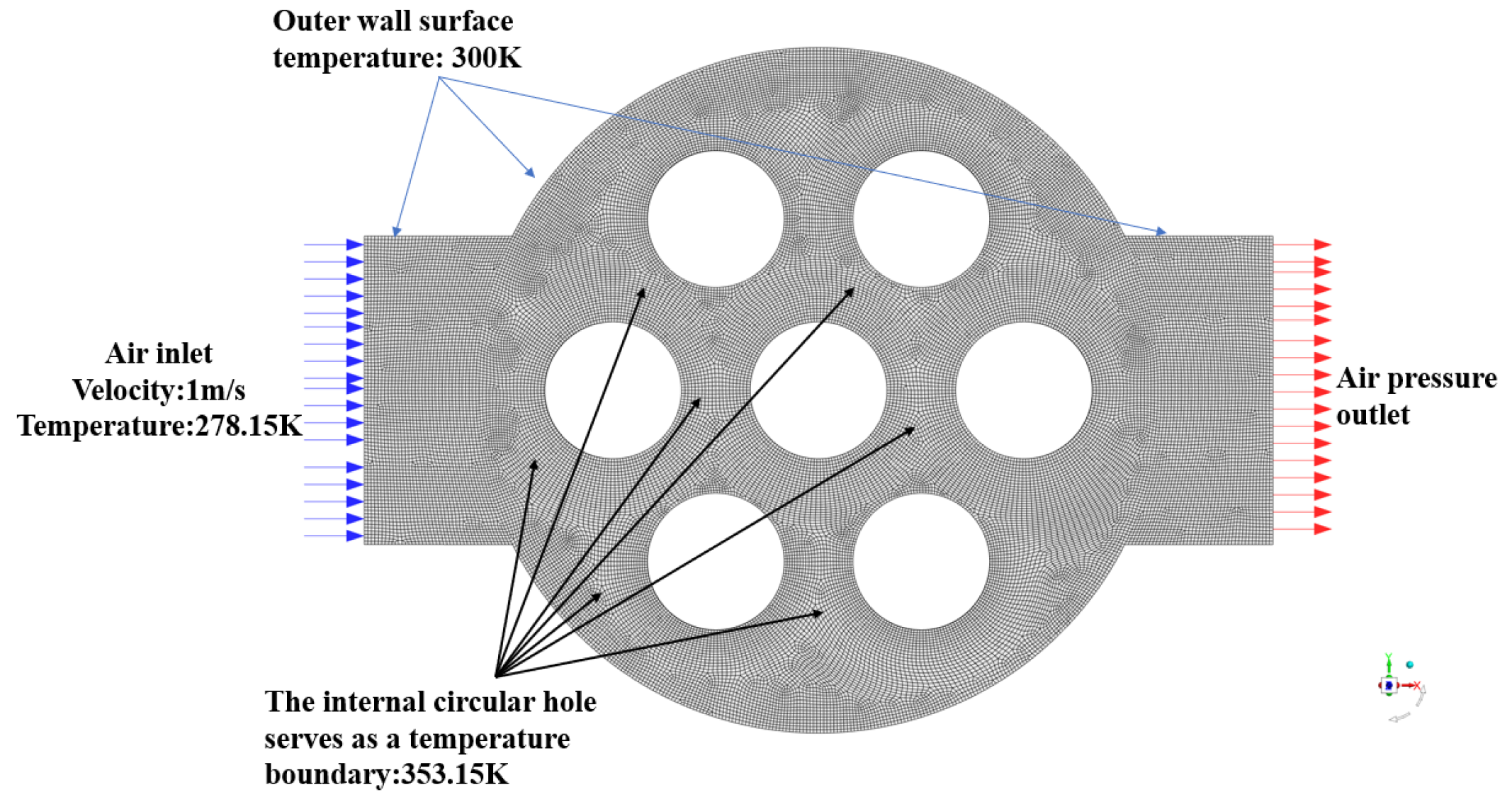
The simplified two-dimensional heat exchanger model was meshed using Hypermesh software, as shown in Figure 11. The model consisted of 30,075 quadrilateral mesh elements, with the air inlet velocity and temperature set to 1 m/s and 278.15 K, respectively, to match the boundary conditions of the three-dimensional prototype. The initial temperature of the outer wall was set to 300 K, and the internal circular holes simulated the water domain of the original three-dimensional model, with a constant boundary temperature of 353.15 K. A pressure boundary condition was applied at the outlet to simulate the fluid exit environment.
Figure 11.
Mesh generation for the simplified two-dimensional heat exchanger.
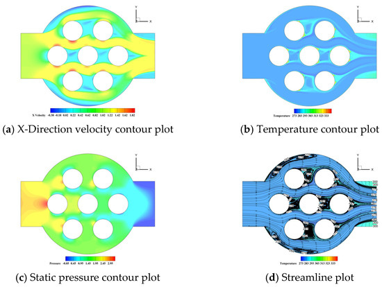
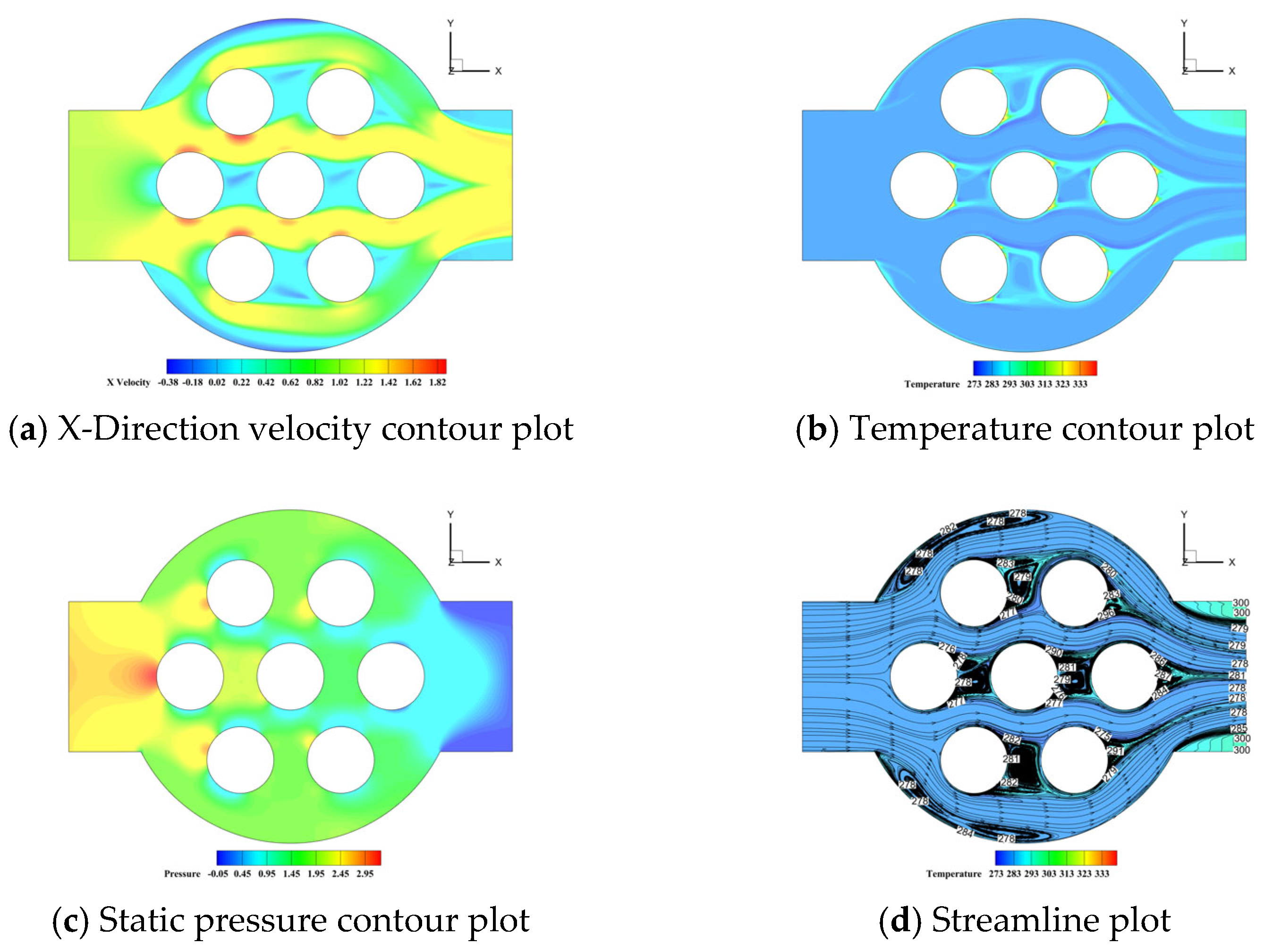
Figure 12 presents the distribution of the X-direction velocity, temperature, static pressure, and streamline diagram for the original flow field. The streamline diagram shows that air forms localized separation vortices after passing through the circular hole. The interactions between these vortices induce turbulent flow, enhancing the exchange efficiency of temperature and velocity in the fluid. The vortices disturb the fluid, disrupting the thermal boundary layer and mixing the warmer fluid near the heat source with the cooler surrounding fluid. Heat transfer occurs not only in the flow direction (X-direction) but also significantly in the vertical direction (Y-direction), thereby improving heat transfer efficiency. This mixing effect improves the overall heat transfer coefficient, enhancing heat transfer efficiency. Additionally, the averaged outlet temperature is approximately 284.76 K.
Figure 12.
Distributions of velocity, temperature, static pressure, and streamlines in the baseline flow field.
3.3. Two-Dimensional Optimization with Respect to the X-Axis Symmetry
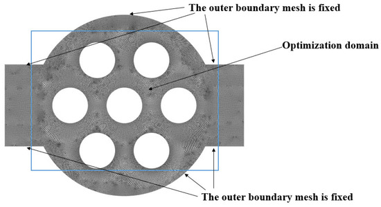
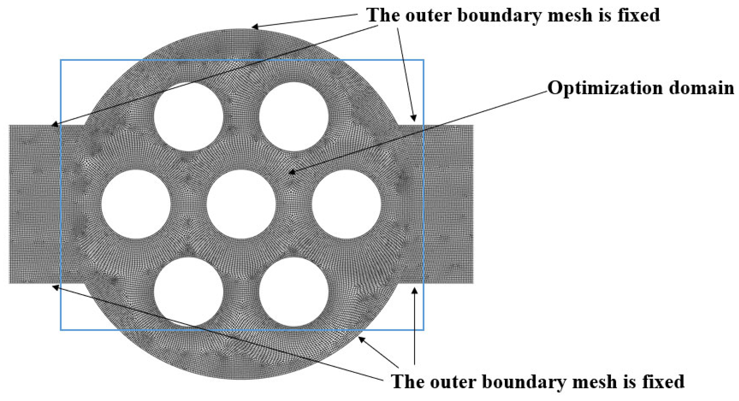
Before adjoint optimization, the forward solution of the flow field was obtained by solving the N-S equations to derive relevant flow parameters such as velocity, pressure, and temperature. The core of the adjoint problem was to construct an adjoint equation linked to the original flow field. The optimization objective of this study was to minimize the average outlet temperature. The adjoint gradient was solved using the Green–Gauss Cell-Based method, and the mesh deformation was handled using radial basis functions, enabling mesh deformation in the regions shown in Figure 13. To simplify the optimization, this study optimized only the internal circular hole boundary while keeping the mesh fixed on the outer wall surface.
Figure 13.
Mesh deformation region for adjoint optimization.
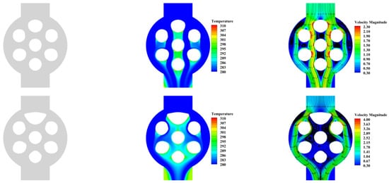
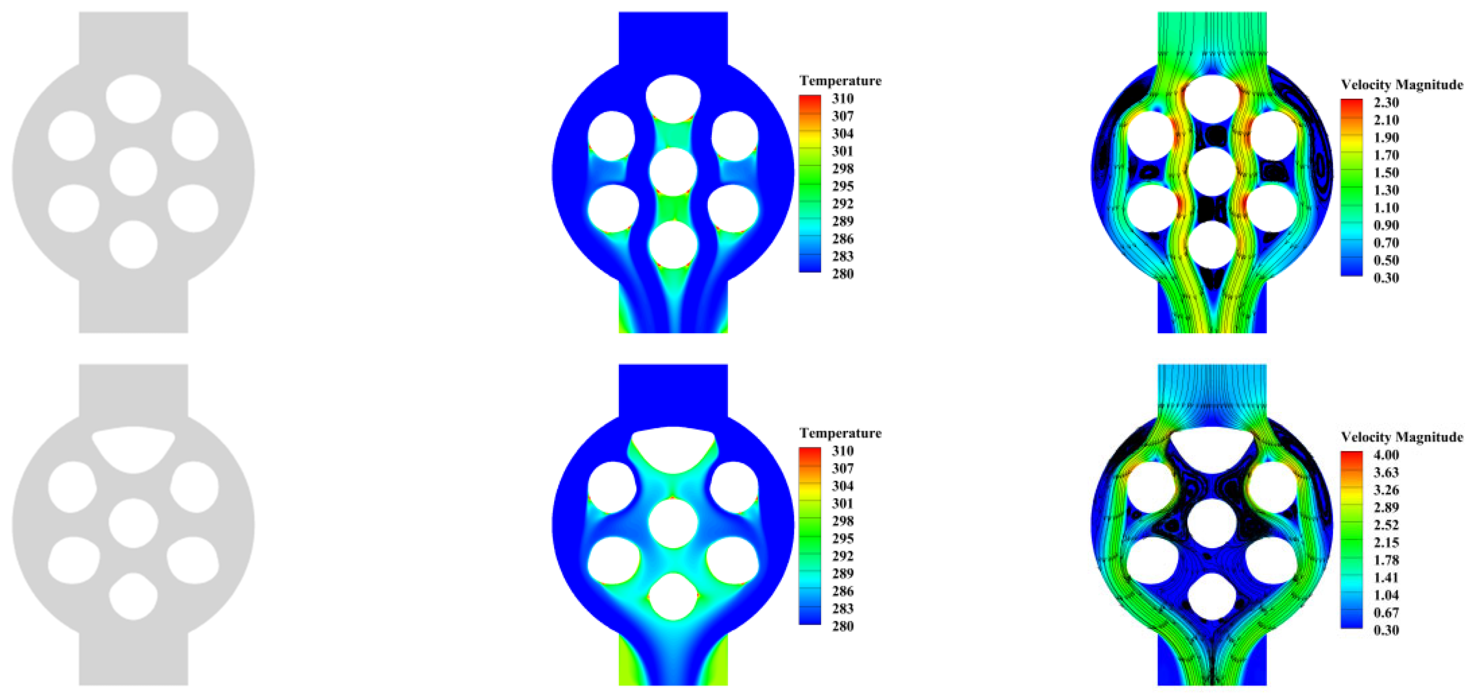
Assuming symmetry of the optimization result with respect to the x-axis, Figure 14 shows the geometry, velocity, temperature, and streamline diagrams after four optimization iterations. The geometric model optimization iteration shows that the upper circular tube gradually enlarges, with significant changes in the transverse dimension and smaller changes in the longitudinal dimension. The other tubes show minimal changes after optimization, transforming from circular to elliptical shapes with slight increases in area. Table 1 presents the original and optimized air outlet temperatures. The significant increase in the upper tube size causes noticeable changes in the flow path, leading to greater energy loss and a sharp decrease in velocity after the air flows around the wall. This provides more time for heat exchange between the air and the circular hole, enhancing heat transfer. As a result, the outlet temperature after optimization is significantly higher.
Figure 14.
Original and iterated geometry, temperature, and streamline diagrams with respect to the x-axis symmetry.
Table 1.
Exit temperature after shape optimization iteration with symmetry constraint.
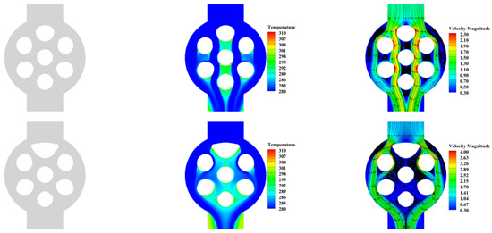
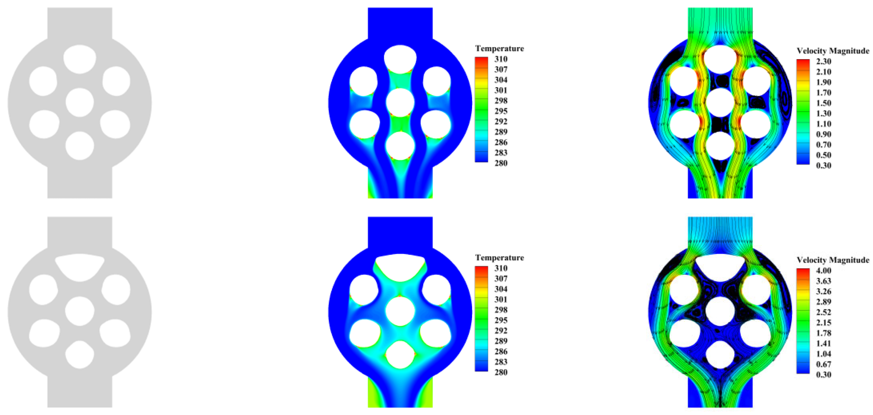
3.4. Two-Dimensional Optimization with Respect to X and Y Bi-Axial Symmetry
In the three-dimensional shell-and-tube heat exchanger, baffles cause the air flow direction to repeatedly reverse. Therefore, simultaneous shape optimization of both the co-current and counter-current flow directions results in more optimal performance. Table 2 presents the outlet temperature results from iterative shape optimization under the x- and y-axis symmetry constraint. The final temperature result from this optimization is higher than that from optimization based solely on x-axis symmetry. Figure 15 displays the geometry, velocity, temperature, and streamline plots after four optimization iterations. The geometric shape iteration shows significant lateral displacement in the upper and lower pipes, with the middle pipe undergoing the largest lateral deformation and the pipes on both sides experiencing twisted deformation. The velocity contour plot shows that, in the narrow flow path, flow speed increases with each iteration. The temperature contour plot shows that as iterations progress, the temperature in the flow field becomes more uniform. The streamline diagram shows that larger flow separation regions lead to higher and more uniform temperatures. Additionally, as the mesh of the pipes on both sides deforms, the flow lines decrease and more flow lines pass through the circular hole, increasing the effective heat exchange area.
Table 2.
Exit temperature after shape optimization iteration with x- and y-axis symmetry constraints.
Figure 15.
Original and optimized iteration geometry, temperature, and streamline diagrams with respect to x-and y-axis symmetry.
3.5. Verification of the Optimization Effect by Extending the Two-Dimensional Adjoint Optimization to Three-Dimensional Optimization
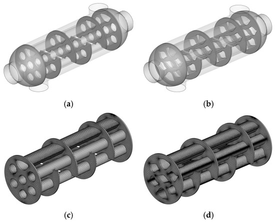
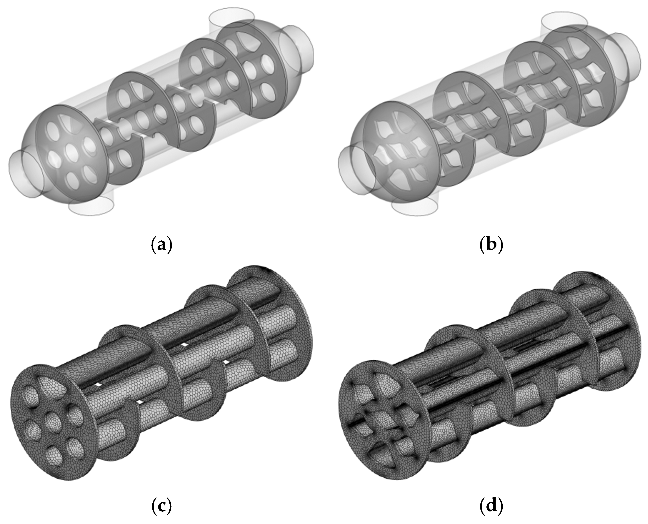
Due to the complexity of fluid motion in the three-dimensional flow field, this study validates the effectiveness of the reduced-dimensional model by stretching the two-dimensional geometry from the previous iteration (Figure 14 and Figure 15) and replacing the original pipe positions, resulting in the new shell-and-tube heat exchanger geometry shown in Figure 16. Figure 16a contains 572,328 polyhedral elements, and Figure 16b contains 1,850,997 polyhedral elements. The volume mesh parameters are maintained as in the original model to minimize mesh-related errors.
Figure 16.
New shell-and-tube heat exchanger geometry model and local mesh display after stretching the two-dimensional optimization result. (a) Two-dimensional optimization stretching result with respect to x-axis symmetry. (b) Two-dimensional optimization stretching result with respect to x- and y-axis symmetry. (c) Local mesh display of the two-dimensional optimization stretching result with respect to x-axis symmetry. (d) Local mesh display of the two-dimensional optimization stretching result with respect to x- and y-axis symmetry.
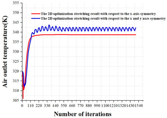
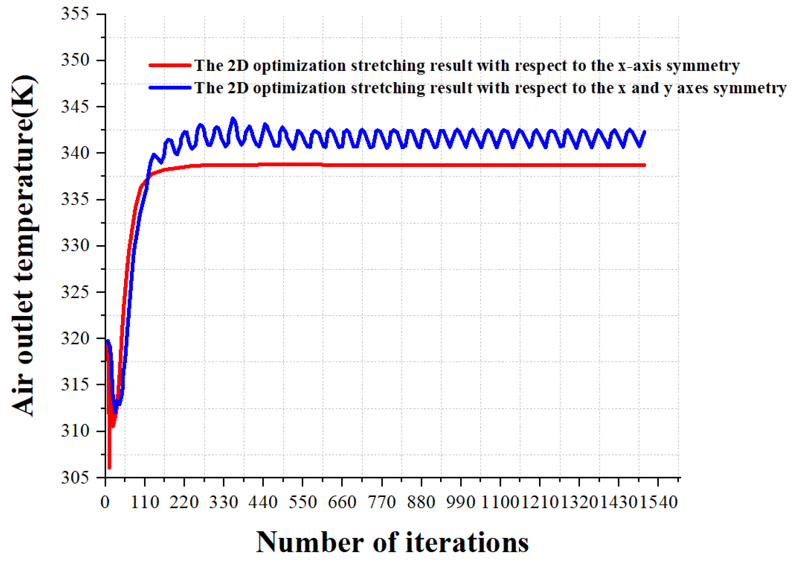
Figure 17 shows the convergence curve of the air outlet temperature after extending to three dimensions. The curve shows a rapid initial temperature rise followed by stabilization after 300 iterations. In this stable region, the blue temperature fluctuates slightly around 341 K due to inherent unsteady flow separation in the pipe. After reaching a certain state, the outlet temperature oscillates steadily, with small fluctuations relative to the mean value, indicating that the temperature curve has stabilized. The red curve remains nearly straight, with a final stable value of 338.72 K.
Figure 17.
Convergence curve of the air outlet temperature after extending the two-dimensional optimization result to three dimensions.
Figure 18 and Figure 19 show the three-dimensional streamline results after two-dimensional optimization stretching with respect to x-axis symmetry, along with temperature, velocity, pressure, and streamline contour plots for each cross-section. The cross-sectional temperature plot shows that, at the same cross-section, the temperature in the optimized flow field is more uniform than in the original flow field. The velocity field oscillations are more pronounced, and more vortices are observed in the streamline plot. The original velocity field is relatively symmetrical, while the optimized velocity field lacks clear symmetry. This indicates that the optimized pipe arrangement increases turbulence in the air domain. The intensified turbulence enhances mixing between different parts of the fluid, accelerating heat transfer, reducing the temperature gradient, and making the optimized temperature field more uniform.
Figure 18.
Spatial streamlines of the three-dimensional model extended from the two-dimensional optimization with respect to x-axis symmetry.
Figure 19.
Contours of temperature, velocity, pressure, and streamlines in inlet, midspan, and outlet cross-sections.
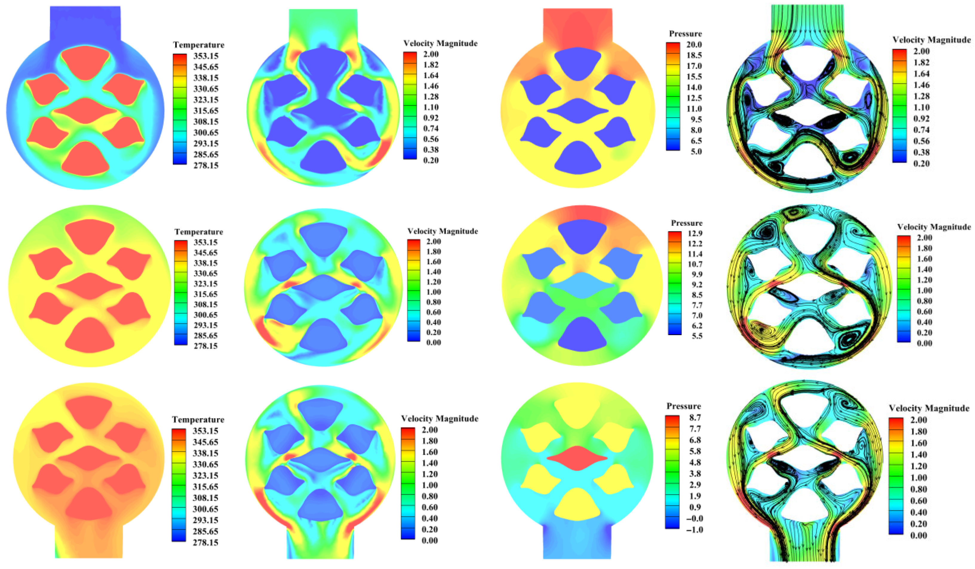
Figure 20 and Figure 21 show the three-dimensional streamline results after two-dimensional optimization stretching with respect to x- and y-axis symmetry, along with temperature, velocity, pressure, and streamline contour plots for each cross-section. In observing the temperature contour plots at different cross-sections, the optimized flow field not only exhibits a more uniform temperature distribution but also shows a significant increase in the overall temperature compared with Figure 19. Additionally, the increased flow oscillations in the velocity field lead to a more complex vortex structure in the streamline plot, further confirming the effectiveness of the optimized design in promoting heat transfer and fluid mixing. This optimization also results in a more symmetric pipe arrangement, optimizing fluid dynamics performance and simplifying the processing and manufacturing processes, thus offering significant practical value in engineering.
Figure 20.
Spatial streamlines of the three-dimensional model extended from the two-dimensional optimization with respect to x- and y-axis symmetry.
Figure 21.
Contours of temperature, velocity, pressure, and streamlines at inlet, midspan, and outlet cross-sections for the optimized design.
A detailed analysis of Figure 19 and Figure 21 reveals that the temperature, velocity, pressure, and streamline contour plots exhibit significant asymmetry, indicating distinct spatial flow characteristics. Conventional simplification methods, such as reducing the complex structure of the shell-and-tube heat exchanger to a symmetric half-model, overlook these key asymmetric features despite being computationally convenient. This simplification may lead to misunderstandings of flow mechanisms, causing significant deviations in both scientific research and industrial production. Given these factors, this study constructs and analyzes a full-size three-dimensional model. Although it requires significantly more computational resources, it provides a complete fluid dynamics perspective, accurately capturing detailed variations within the flow field and ensuring that the design and analysis are closer to real-world conditions.
4. Conclusions
In this study, the complex three-dimensional shell-and-tube heat exchanger is simplified into a pseudo-three-dimensional reduced model through adjoint geometric optimization, and two-dimensional adjoint shape optimization is performed based on x-axis and x- and y-axis double symmetry. This significantly improves heat transfer efficiency and model symmetrical characteristics, making it easier to install during construction. Given that geometric discrepancies between the 2D and 3D models may alter flow and heat transfer characteristics and thus impact performance, for this paper, we developed three-dimensional models from the 2D optimization outcomes with the aim of verifying the effectiveness of the planar optimization. Detailed analysis was performed using the flow characteristics, temperature, velocity, pressure, and streamline contour plots of the cross-sections of each three-dimensional model. The results show that the optimized design increased the average air outlet temperature of the three-dimensional shell-and-tube heat exchanger by 5.35 K and 3.07 K, respectively, compared with the original design. Analysis of the flow field and cross-sections shows that the optimized pipe layout caused more flow separation, generating stronger turbulence. Through enhanced fluid mixing, the intense turbulence promoted heat transfer and diminished the temperature gradient, resulting in a more uniform temperature field. The three-dimensional pipe model presented in this paper can be easily fabricated using mature molding processes. Compared to techniques for complex-shaped pipes, this approach reduces manufacturing costs and facilitates broader application.
In scenarios with higher heat transfer efficiency requirements and less stringent cost constraints, future work could explore three-dimensional shape optimization, supported by advanced additive manufacturing technologies such as 3D printing, to meet complex geometric design requirements.
Author Contributions
Conceptualization, X.Y. and H.D.; methodology, X.Y., M.L. and H.D.; software, X.Y. and M.L.; validation, M.L. and P.L.; formal analysis, X.Y. and M.L.; investigation, X.Y., M.L. and Z.D.; resources, P.L. and H.D.; data curation, P.L.; writing—original draft, X.Y., Z.D. and Y.C.; writing—review and editing, X.Y., Z.D., P.L., H.D. and Y.C.; visualization, Z.D. and Y.C.; supervision, H.D. and Y.C.; project administration, H.D. and Y.C.; funding acquisition, Y.C. All authors have read and agreed to the published version of the manuscript.
Funding
This research was supported by the Natural Science Foundation of Shaanxi Province (No. 2025JC-YBQN-671), the China Postdoctoral Science Foundation (No. 2025M770580), and the Postdoctoral Research Project Funding of Shaanxi Province (2025BSHSDZZ257).
Data Availability Statement
The original contributions presented in this study are included in the article. Further inquiries can be directed to the corresponding authors.
Conflicts of Interest
The author Pengfeng Li is employed by the Power China Northwest Engineering Corporation Limited. The remaining authors declare that this research was conducted in the absence of any commercial or financial relationships that could be construed as potential conflicts of interest.
References
- Pethkool, S.; Eiamsa-Ard, S.; Kwankaomeng, S.; Promvonge, P. Turbulent heat transfer enhancement in a heat exchanger using helically corrugated tube. Int. Commun. Heat Mass Transf. 2011, 38, 340–347. [Google Scholar] [CrossRef] [Scilit]
- Córcoles-Tendero, J.; Belmonte, J.; Molina, A.; Almendros-Ibáñez, J. Numerical simulation of the heat transfer process in a corrugated tube. Int. J. Therm. Sci. 2018, 126, 125–136. [Google Scholar] [CrossRef] [Scilit]
- Gao, G.; Feng, Z.; Cai, Y.; Luo, T.; Song, M.; Zhu, X. Numerical analysis of full-scale multi-path shell-and-tube heat exchangers with corrugated tubes. Int. Commun. Heat Mass Transf. 2025, 161, 108402. [Google Scholar] [CrossRef] [Scilit]
- Yang, B.; Yu, X.; Zheng, Y.; Yang, S.; Yang, Q.; Qiao, D.; Sun, Y.; Li, Y. Numerical analysis of fin optimization for a shell-and-tube phase change energy storage heat exchanger. Energy Storage Sci. Technol. 2025, 14, 1394. [Google Scholar]
- Amini, R.; Amini, M.; Jafarinia, A.; Kashfi, M. Numerical investigation on effects of using segmented and helical tube fins on thermal performance and efficiency of a shell and tube heat exchanger. Appl. Therm. Eng. 2018, 138, 750–760. [Google Scholar] [CrossRef] [Scilit]
- Alimoradi, A.; Olfati, M.; Maghareh, M. Numerical investigation of heat transfer intensification in shell and helically coiled finned tube heat exchangers and design optimization. Chem. Eng. Process. Process Intensif. 2017, 121, 125–143. [Google Scholar] [CrossRef] [Scilit]
- Maghsoudali, Y.; Rastegarkoutenaei, A.; Sahami, M.; Bandpy, M.G. Investigation of the effect of using the finned tubes on the performance of shell and tube heat exchanger by 3D modeling. J. Energy Storage 2022, 56, 106031. [Google Scholar] [CrossRef] [Scilit]
- Khoshvaght-Aliabadi, M.; Feizabadi, A. Performance intensification of tubular heat exchangers using compound twisted-tape and twisted-tube. Chem. Eng. Process.-Process Intensif. 2020, 148, 107799. [Google Scholar] [CrossRef] [Scilit]
- Al-Mosallam, M.; Ali, A.B.; Shrama, S.M.; Fares, M.N.; Karouei, S.H.H.; Jasim, D.J.; Alinia-kolaei, M. Numerical study of the heat transfer characteristics of two distinct spiral coil configurations with the insertion of twisted tape in a shell and tube heat exchanger. Case Stud. Therm. Eng. 2025, 74, 106672. [Google Scholar] [CrossRef] [Scilit]
- Ayub, Z.H.; Yang, D.; Khan, T.S.; Al-Hajri, E.; Ayub, A.H. Performance characteristics of a novel shell and tube heat exchanger with shell side interstitial twisted tapes for viscous fluids application. Appl. Therm. Eng. 2018, 134, 248–255. [Google Scholar] [CrossRef] [Scilit]
- Yang, D.; Khan, T.S.; Al-Hajri, E.; Ayub, Z.H.; Ayub, A.H. Geometric optimization of shell and tube heat exchanger with interstitial twisted tapes outside the tubes applying CFD techniques. Appl. Therm. Eng. 2019, 152, 559–572. [Google Scholar] [CrossRef] [Scilit]
- Jia, B.; Song, Z.; Li, X.; Hu, Z.; Li, Q. Enhancing thermal performance: The evolution and future of solar air heaters with baffles. Case Stud. Therm. Eng. 2025, 75, 107163. [Google Scholar] [CrossRef] [Scilit]
- Mohammadzadeh, A.; Jafari, B.; Hosseinzadeh, K.; Paikar, E. Numerical investigation of segmental baffle design in shell and tube heat exchangers with varying inclination angles and spacing. Sci. Rep. 2025, 15, 4683. [Google Scholar] [CrossRef] [Scilit] [PubMed]
- El-Said, E.M.; Elsheikh, A.H.; El-Tahan, H.R. Effect of curved segmental baffle on a shell and tube heat exchanger thermohydraulic performance: Numerical investigation. Int. J. Therm. Sci. 2021, 165, 106922. [Google Scholar] [CrossRef] [Scilit]
- Salahuddin, U.; Bilal, M.; Ejaz, H. A review of the advancements made in helical baffles used in shell and tube heat exchangers. Int. Commun. Heat Mass Transf. 2015, 67, 104–108. [Google Scholar] [CrossRef] [Scilit]
- Yang, J.-F.; Lin, Y.-S.; Ke, H.-B.; Zeng, M.; Wang, Q.-W. Investigation on combined multiple shell-pass shell-and-tube heat exchanger with continuous helical baffles. Energy 2016, 115, 1572–1579. [Google Scholar] [CrossRef] [Scilit]
- Chen, J.; Lu, X.; Wang, Q.; Zeng, M. Experimental investigation on thermal-hydraulic performance of a novel shell-and-tube heat exchanger with unilateral ladder type helical baffles. Appl. Therm. Eng. 2019, 161, 114099. [Google Scholar] [CrossRef] [Scilit]
- Wen, J.; Yang, H.; Wang, S.; Xue, Y.; Tong, X. Experimental investigation on performance comparison for shell-and-tube heat exchangers with different baffles. Int. J. Heat Mass Transf. 2015, 84, 990–997. [Google Scholar] [CrossRef] [Scilit]
- Yang, J.-F.; Zeng, M.; Wang, Q.-W. Numerical investigation on combined single shell-pass shell-and-tube heat exchanger with two-layer continuous helical baffles. Int. J. Heat Mass Transf. 2015, 84, 103–113. [Google Scholar] [CrossRef] [Scilit]
- Khan, A.U.A.; Cheema, T.A.; Rizwan, H.M.; Ullah, R.; Tayyab, M.; Park, C.W. Shell and tube heat exchange comparison with gravitational water vortex flow configuration. Appl. Therm. Eng. 2024, 238, 122000. [Google Scholar] [CrossRef] [Scilit]
- Yu, C.; Zhang, H.; Zeng, M.; Wang, R.; Gao, B. Numerical study on turbulent heat transfer performance of a new compound parallel flow shell and tube heat exchanger with longitudinal vortex generator. Appl. Therm. Eng. 2020, 164, 114449. [Google Scholar] [CrossRef] [Scilit]
- Yu, C.; Wang, Y.; Zhang, H.; Zeng, M.; Gao, B.; Fang, Z. Numerical investigation on turbulent thermal performance of parallel flow heat exchanger with a novel polyhedral longitudinal vortex generator in shell side. Int. J. Therm. Sci. 2021, 166, 106962. [Google Scholar] [CrossRef] [Scilit]
- Ambekar, A.S.; Sivakumar, R.; Anantharaman, N.; Vivekenandan, M. CFD simulation study of shell and tube heat exchangers with different baffle segment configurations. Appl. Therm. Eng. 2016, 108, 999–1007. [Google Scholar] [CrossRef] [Scilit]
- El Maakoul, A.; Laknizi, A.; Saadeddine, S.; El Metoui, M.; Zaite, A.; Meziane, M.; Abdellah, A.B. Numerical comparison of shell-side performance for shell and tube heat exchangers with trefoil-hole, helical and segmental baffles. Appl. Therm. Eng. 2016, 109, 175–185. [Google Scholar] [CrossRef] [Scilit]
- Mohammadi, M.H.; Abbasi, H.R.; Yavarinasab, A.; Pourrahmani, H. Thermal optimization of shell and tube heat exchanger using porous baffles. Appl. Therm. Eng. 2020, 170, 115005. [Google Scholar] [CrossRef] [Scilit]
- Selbaş, R.; Kızılkan, Ö.; Reppich, M. A new design approach for shell-and-tube heat exchangers using genetic algorithms from economic point of view. Chem. Eng. Process. Process Intensif. 2006, 45, 268–275. [Google Scholar] [CrossRef] [Scilit]
- Özçelik, Y. Exergetic optimization of shell and tube heat exchangers using a genetic based algorithm. Appl. Therm. Eng. 2007, 27, 1849–1856. [Google Scholar] [CrossRef] [Scilit]
- Sadeghzadeh, H.; Ehyaei, M.; Rosen, M. Techno-economic optimization of a shell and tube heat exchanger by genetic and particle swarm algorithms. Energy Convers. Manag. 2015, 93, 84–91. [Google Scholar] [CrossRef] [Scilit]
- Şahin, A.Ş.; Kılıç, B.; Kılıç, U. Design and economic optimization of shell and tube heat exchangers using Artificial Bee Colony (ABC) algorithm. Energy Convers. Manag. 2011, 52, 3356–3362. [Google Scholar] [CrossRef] [Scilit]
- Tharakeshwar, T.; Seetharamu, K.; Prasad, B.D. Multi-objective optimization using bat algorithm for shell and tube heat exchangers. Appl. Therm. Eng. 2017, 110, 1029–1038. [Google Scholar] [CrossRef] [Scilit]
- Sanaye, S.; Hajabdollahi, H. Multi-objective optimization of shell and tube heat exchangers. Appl. Therm. Eng. 2010, 30, 1937–1945. [Google Scholar] [CrossRef] [Scilit]
- Mirzaei, M.; Hajabdollahi, H.; Fadakar, H. Multi-objective optimization of shell-and-tube heat exchanger by constructal theory. Appl. Therm. Eng. 2017, 125, 9–19. [Google Scholar] [CrossRef] [Scilit]
- Wang, C.; Cui, Z.; Yu, H.; Chen, K.; Wang, J. Intelligent optimization design of shell and helically coiled tube heat exchanger based on genetic algorithm. Int. J. Heat Mass Transf. 2020, 159, 120140. [Google Scholar] [CrossRef] [Scilit]
- Luo, J.; Xiong, J.; Liu, F. Aerodynamic design optimization by using a continuous adjoint method. Sci. China Phys. Mech. Astron. 2014, 57, 1363–1375. [Google Scholar] [CrossRef] [Scilit]
- Jameson, A. Aerodynamic design via control theory. J. Sci. Comput. 1988, 3, 233–260. [Google Scholar] [CrossRef] [Scilit]
- Papoutsis-Kiachagias, E.M.; Giannakoglou, K.C. Continuous adjoint methods for turbulent flows, applied to shape and topology optimization: Industrial applications. Arch. Comput. Methods Eng. 2016, 23, 255–299. [Google Scholar] [CrossRef] [Scilit]
- Georgieva, N.K.; Glavic, S.; Bakr, M.H.; Bandler, J.W. Feasible adjoint sensitivity technique for EM design optimization. IEEE Trans. Microw. Theory Tech. 2002, 50, 2751–2758. [Google Scholar] [CrossRef] [Scilit]
- Song, J.; Chen, C.; Guo, Z.; Geng, M.; Rong, Z.; Wang, T.; Wang, J.; Fan, J.; Sun, Y. Analysis of Flow Field, Temperature, and Inclusion Evolution in a 12-Strand Tundish During Ladle Changeover Process. Metall. Mater. Trans. B 2025, 56, 2700–2714. [Google Scholar] [CrossRef] [Scilit]
- Patankar, S.V. Numerical Heat Transfer and Fluid Flow; Hemisphere Publ. Corp.: New York, NY, USA, 1980; Volume 58, p. 288. [Google Scholar]
- Liu, J.; Qian, C. Comparison of the fluid flow and heat transfer in shell-and-tube heat exchangers with different baffles and tubes: Simulation and experimental studies. Asia-Pac. J. Chem. Eng. 2016, 11, 1051–1059. [Google Scholar] [CrossRef] [Scilit]
- Haertel, J.H.; Engelbrecht, K.; Lazarov, B.S.; Sigmund, O. Topology optimization of a pseudo 3D thermofluid heat sink model. Int. J. Heat Mass Transf. 2018, 121, 1073–1088. [Google Scholar] [CrossRef] [Scilit]

Disclaimer/Publisher’s Note: The statements, opinions and data contained in all publications are solely those of the individual author(s) and contributor(s) and not of MDPI and/or the editor(s). MDPI and/or the editor(s) disclaim responsibility for any injury to people or property resulting from any ideas, methods, instructions or products referred to in the content. |
© 2026 by the authors. Licensee MDPI, Basel, Switzerland. This article is an open access article distributed under the terms and conditions of the Creative Commons Attribution (CC BY) license.