


Abstract
Clayey-silt gas hydrate reservoirs in the northern South China Sea are characterized by weak consolidation, fine-grained sediments, and high clay contents, making sand-control screens (SCSs) susceptible to progressive plugging during long-term production. This study investigates the plugging mechanisms of SCSs and evaluates a physical–chemical composite plug-removal method for clayey-silt gas hydrate reservoirs. X-ray diffraction (XRD), hydrate dissociation, long-term plugging, mineral dissolution, chemical plug-removal, and high-pressure water-jet experiments were conducted, together with computational fluid dynamics–discrete element method (CFD–DEM) simulations revealing the progressive transition from particle migration and deposition to pore-throat blockage under coupled fluid–particle interactions. The results show that the clay-mineral content increased from approximately 36.4% in the original sediment to 41.5% in the plugging layer, accompanied by enrichment of montmorillonite and ordered illite/smectite mixed-layer minerals. Screen plugging developed progressively from initial particle bridging to fine-particle invasion and pore-throat locking, followed by progressive compaction and structural stabilization. A mud-acid system containing 10% HCl and 2% HF was selected as the core chemical treatment for weakening the carbonate–silicate composite plugging structure, while dispersing, chelating, and hydrate-inhibiting agents were used as auxiliary components. High-pressure water jetting achieved plug-removal efficiencies of 12.4–46.2% depending on the plugging stage and operating conditions. After chemical pretreatment followed by water-jet stripping, the composite method achieved pressure-drop reduction ratios of 74.1–78.0%, 64.6–69.6%, and 85.1–85.6% at the initial, middle, and late plugging stages, respectively. These results demonstrate that chemical weakening followed by mechanical stripping provides an effective approach for restoring the flow capacity of plugged SCSs in clayey-silt gas hydrate reservoirs.
1. Introduction
Natural gas hydrates (NGHs) are crystalline inclusion compounds formed by water molecules and gas molecules, predominantly methane, under low-temperature and high-pressure conditions. They are widely distributed in permafrost regions and deep-sea sediments and have attracted considerable attention as a potential unconventional natural gas resource [1,2,3]. In China, large-scale hydrate accumulations have been identified in the northern South China Sea, where offshore production trials in the Shenhu area (2017 and 2020) demonstrated the technical feasibility of gas hydrate exploitation [4,5]. However, hydrate-bearing sediments in this region are predominantly clayey-silt deposits characterized by fine particle sizes, weak consolidation, high clay contents, and low permeability. These properties make the reservoir highly susceptible to particle migration, structural weakening, and sand production during hydrate exploitation, posing significant challenges to long-term and stable gas production.
Sand production is one of the major engineering challenges affecting the safe and stable exploitation of gas hydrate reservoirs [6,7,8]. Accordingly, effective sand control is essential for maintaining long-term well productivity. Various sand-control methods, including mechanical screens, gravel packing, and composite sand-control systems, have been developed for hydrate-bearing sediments; however, this study specifically focuses on pre-packed composite sand-control screens (SCSs), consisting of an outer slotted screen, a ceramic-proppant packing layer, an inner slotted screen, and a perforated base pipe. Plugging may therefore develop not only at the screen openings but also within the internal packing medium during long-term production [8,9]. However, the fine-grained and weakly consolidated nature of clayey-silt reservoirs poses a particular challenge: although sand-control structures can retain formation particles, continuously migrating fine silt and clay particles may accumulate at screen openings, invade the internal packing medium, and progressively reduce pore connectivity [9,10,11,12,13,14]. Under the low-temperature and high-pressure conditions of hydrate reservoirs, hydrate phase changes and mineral cementation may further complicate the plugging process [15]. Consequently, the sand-control screen (SCS) itself can gradually evolve from a protective sand-retention structure into a major flow-resistance zone during long-term production. Understanding the time-dependent plugging mechanism of SCSs is therefore a prerequisite for developing effective plug-removal technologies.
Existing methods for hydrate blockage removal mainly include depressurization, thermal stimulation, mechanical removal, and chemical inhibition [16,17,18,19]. Depressurization and heating promote hydrate dissociation by shifting the local pressure–temperature conditions away from the hydrate stability region, whereas thermodynamic or kinetic inhibitors are used to suppress hydrate formation or growth. However, these approaches primarily target hydrate itself and are therefore insufficient for screen plugging involving accumulated fine particles, clay minerals, and mineral cementation. In conventional oil and gas wells, acid washing, sand washing, and water jetting have been widely used for screen cleaning and near-wellbore plug removal. Acid treatment can dissolve reactive mineral components and weaken the bonding within the plugging layer [20,21], but residual solid particles may remain attached to or trapped within the screen structure. Water jetting provides direct mechanical impact and shear for particle detachment [22,23]; however, its effectiveness decreases when the plugging layer becomes compacted or cemented, and rotating jetting tools may also be susceptible to blockage by entrained sand and mud. These limitations indicate that a single physical or chemical treatment may be inadequate for the multi-component and structurally complex plugging encountered in clayey-silt gas hydrate reservoirs.
Despite advances in sand-control design and conventional screen-cleaning technologies, the time-dependent plugging behavior of SCSs in clayey-silt gas hydrate reservoirs and its implications for plug removal remain insufficiently understood. In particular, screen plugging is not governed solely by surface particle deposition. Fine particles can progressively migrate into the internal packing medium, accumulate at pore throats, and form increasingly compact structures, while clay-mineral interactions, mineral cementation, and hydrate phase changes may further modify the strength and stability of the plugging layer. Consequently, neither chemical dissolution nor mechanical cleaning alone is expected to address all components and structural characteristics of the plug. Based on this consideration, this study develops a physical–chemical composite strategy in which chemical treatment first dissolves reactive mineral components, disperses fine particles, and weakens the plugging structure, followed by high-pressure water jetting to detach and transport the loosened plugging material.
Accordingly, this study aims to systematically investigate the plugging mechanisms of SCSs and develop an effective physical–chemical composite plug-removal technology for clayey-silt gas hydrate reservoirs. The specific objectives are to (1) characterize the mineralogical features of the reservoir sediment and plugging layer and identify the principal factors associated with screen plugging; (2) clarify the time-dependent migration, deposition, bridging, pore-throat locking, and compaction of fine particles through long-term plugging experiments and CFD–DEM simulations; (3) evaluate the mineral-selective dissolution behavior of different chemical agents and screen suitable acid, dispersing, chelating, and hydrate-inhibiting components; and (4) evaluate high-pressure water-jet removal and establish a composite procedure combining chemical pretreatment with subsequent mechanical stripping. The results provide an experimental basis for understanding progressive SCS plugging and for improving flow-capacity restoration in clayey-silt gas hydrate production wells.
2. Materials and Methods
2.1. Materials
Two types of sediment samples were used in this study: formulated reservoir sediment and deep-sea mud. The formulated sediment was prepared according to the reported mineral composition of hydrate-bearing sediments from borehole SH7B in the Shenhu area of the northern South China Sea. The major mineral fractions used for sample formulation were 18.68 wt.% muscovite, 27.27 wt.% quartz, 3.60 wt.% K-feldspar, 7.99 wt.% plagioclase, 7.24 wt.% illite, 6.84 wt.% montmorillonite, 1.78 wt.% kaolinite, 2.99 wt.% chlorite, and 19.93 wt.% calcite. The median particle size of hydrate-bearing sediments in this area is approximately 16.0–25.0 μm, reflecting the fine-grained characteristics of the clayey-silt reservoir. Deep-sea mud samples collected from the Shenhu area were additionally used to evaluate the response of field-collected sediment to different plug-removal agents.
High-purity quartz, K-feldspar, muscovite, plagioclase, montmorillonite, illite, chlorite, calcite, and kaolinite were used in the single-mineral dissolution tests and for preparation of the formulated sediment. Before use, the mineral powders were dried, gently ground, and sieved to obtain relatively uniform particle-size distributions, ensuring consistency during sediment preparation. The principal acid reagents included 36 wt.% HCl solution (Hubei Zhixing Technology Co., Ltd., Hubei Province, China), 50 wt.% HF solution (Liaoning Zhisheng Co., Ltd., Liaoning Province, China), and commercially available 65 wt.% HNO3 solution. These concentrated acid solutions were used as laboratory-scale chemical reagents to evaluate mineral dissolution and weakening behavior, rather than as direct field-scale treatment formulations. Additional acids used for comparative mineral-dissolution tests included acetic acid, sulfamic acid, and sulfuric acid. Functional chemical agents evaluated for plug removal included clay dispersants, chelating agents, and hydrate inhibitors. The screened agents included sodium lignosulfonate, sodium polyacrylate (PAAS), an amphoteric quaternary-ammonium dispersant, sodium hexametaphosphate, sodium dodecylbenzenesulfonate (SDBS), ethylenediaminetetraacetic acid (EDTA), diethylenetriaminepentaacetic acid (DTPA), glutamic acid diacetic acid (GLDA), sodium citrate, methanol (MeOH), monoethylene glycol (MEG), polyvinylpyrrolidone (PVP), and cetyltrimethylammonium bromide (CTAB). All functional agents were commercially available reagent-grade chemicals procured through the project procurement system.
2.2. Mineralogical Characterization and Chemical-Removal Experiments
X-ray diffraction (XRD) analysis was conducted to characterize both the bulk-mineral and clay-mineral compositions associated with screen plugging. The measurements were performed using a D8 Advance X-ray diffractometer (Bruker AXS GmbH, Karlsruhe, Germany) equipped with Cu Kα radiation. Diffraction data were collected following conventional mineralogical analysis procedures, with a scanning range of 5–70° (2θ), a step size of 0.02°, and a scanning speed of 2°/min. The mineral phases were identified by comparing the diffraction peaks with reference databases. For bulk-mineral characterization, ten original sediment samples and ten plugging-layer samples were analyzed to determine the relative contents of quartz, feldspars, calcite, halite, and total clay minerals. Clay-mineral assemblages were separately quantified for ten hydrate-bearing sediment samples and ten plugging-layer samples to determine the distributions of montmorillonite, illite, illite/smectite mixed-layer minerals (I/S), kaolinite, and chlorite. The clay fractions were prepared following conventional clay-mineral characterization procedures, with fine clay particles separated before mineral identification and semi-quantitative analysis. Relative mineral contents were estimated based on characteristic diffraction peak intensities using semi-quantitative analysis methods. The two datasets were subsequently compared to identify mineralogical changes associated with screen plugging.
Chemical-removal experiments were conducted using both formulated reservoir sediment and deep-sea mud. For each test, 10.00 g of sample was mixed with 100 mL of the designated chemical solution at a solid-to-liquid ratio of 1:10 and reacted at room temperature for 2 h. After reaction, the solid and liquid phases were separated by filtration. The residual solid was washed with deionized water, dried at 60 °C, and weighed. The solid-mass loss rate, RA, was calculated as
where m0 and m1 are the dry sample masses before and after treatment, respectively. Single-mineral dissolution tests were conducted using quartz, feldspars, calcite, and representative clay minerals to evaluate the mineral selectivity of different acid systems. The sample mass was adjusted according to mineral type, while the general dissolution procedure remained consistent with that used for the formulated sediment and deep-sea mud.
2.3. Hydrate Synthesis and Dissociation Experiments
Methane hydrate-bearing sediment samples were synthesized in situ using a custom-built high-pressure hydrate kinetics evaluation system developed for this project. The formulated reservoir sediment was packed into the high-pressure reactor in layers and compacted to obtain the prescribed initial packing condition. The aqueous phase was added during specimen preparation and kept consistent among the comparative hydrate-synthesis tests. No independent salinity adjustment was recorded in the available experimental documentation. The comparative tests followed the same specimen-preparation and hydrate-formation procedure; however, the initial hydrate inventory and hydrate saturation were not independently quantified. Therefore, the released-gas volume was used as a comparative response parameter rather than as an absolute measure of hydrate conversion. The reactor was subsequently evacuated to remove residual gas and then charged with high-purity methane. A low-temperature circulating bath was used to reduce the system temperature to 2–6 °C. Hydrate formation was monitored continuously through changes in system pressure, temperature, and gas consumption. Hydrate formation was considered substantially complete when the system pressure became stable and no pronounced variation was observed.
The initial hydrate saturation and absolute hydrate inventory were not independently quantified. Therefore, the subsequent dissociation experiments were designed as comparative tests under a consistent specimen-preparation and hydrate-formation procedure, and the measured gas-release volume was used to evaluate the relative response of hydrate stability to different operating conditions.
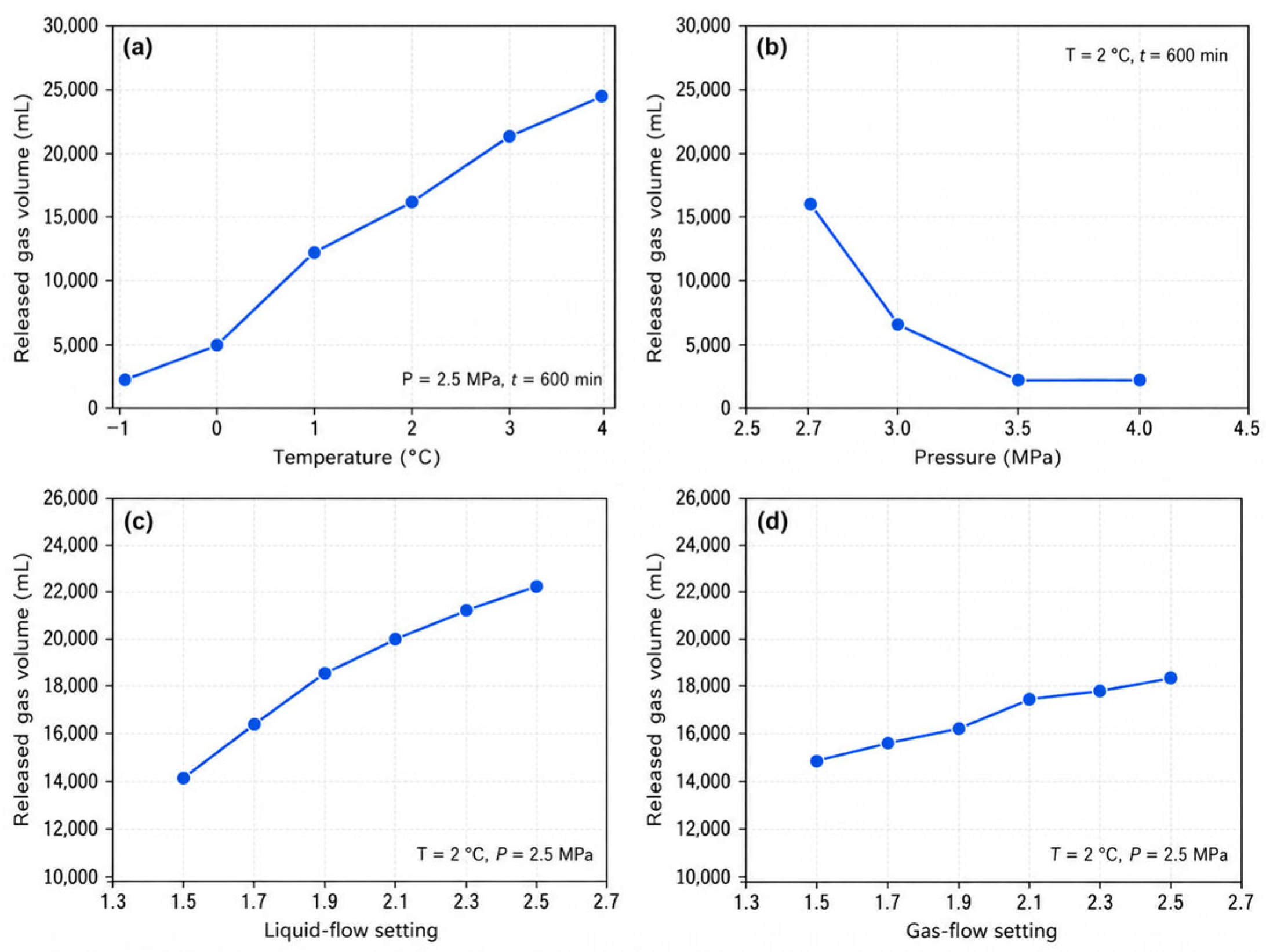
Hydrate dissociation experiments were subsequently performed to investigate the effects of temperature, pressure, and fluid-flow conditions on hydrate stability. The dissociation process was initiated by adjusting the system pressure and introducing flow disturbance rather than by directly increasing the temperature or adding chemical inhibitors. For the temperature tests, the dissociation pressure was maintained at 2.5 MPa and the dissociation time was 600 min, while the temperature was varied from −1 to 4 °C. For the pressure tests, the temperature was maintained at 2 °C, while the system pressure was gradually adjusted within the range of 2.7–4.0 MPa to evaluate hydrate response under different pressure conditions. Additional flow-disturbance tests were performed at 2 °C and 2.5 MPa for 600 min. For the liquid-flow tests, the gas flow rate was fixed at 1.8 m3/h, while the liquid flow rate was varied from 1.5 to 2.5 m3/h at 0.2 m3/h intervals. For the gas-flow tests, the liquid flow rate was fixed at 2.0 m3/h, while the gas flow rate was varied from 1.5 to 2.5 m3/h at 0.2 m3/h intervals. During each experiment, released gas volume and the corresponding temperature and pressure responses were continuously recorded to characterize the hydrate dissociation behavior. The reported gas-release volumes correspond to the directly recorded experimental values; no additional correction for dissolved methane or conversion to an absolute hydrate-conversion fraction was applied in the comparative analysis.
2.4. Screen-Plugging Apparatus, Long-Term Experiments, and CFD–DEM Simulation
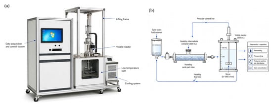
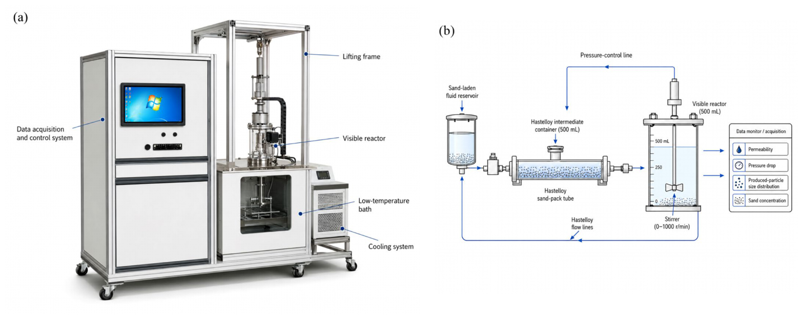
An SCS plugging simulation and evaluation system was developed by modifying an existing deep-water hydrate dynamic circulation apparatus to enable hydrate formation/dissociation, particle migration, and plugging experiments under controlled high-pressure and low-temperature conditions. The system has a maximum operating pressure of 25 MPa and an operating temperature range of −10 to 80 °C, with a temperature-control accuracy of ±0.05 °C and a pressure-measurement accuracy of 0.1% F.S. The high-pressure reactor has a volume of 500 mL, and the stirring speed can be adjusted from 0 to 1000 r/min. A Hastelloy sand-pack tube with a diameter of 25 mm, a length of 300 mm, and a pressure rating of 32 MPa was incorporated into the system. A 500 mL Hastelloy intermediate vessel and corrosion-resistant high-pressure flow lines were also employed to accommodate saline and acidic fluids. The system was operated using PLC-based control and data-acquisition software custom-developed for this experimental apparatus; therefore, no commercial software version number or website is applicable. The improved experimental apparatus and the simplified plugging-test flow loop are shown in Figure 1a,b, respectively.
Figure 1.
Experimental system used for SCS plugging evaluation: (a) schematic rendering of the improved high-pressure, low-temperature experimental apparatus; (b) simplified schematic of the SCS plugging-test flow loop and monitored parameters.
Long-term plugging experiments were conducted by continuously introducing particle-laden fluid through the screen system. To minimize particle settling before entering the screen, the particle-laden suspension was maintained under continuous agitation in the feed vessel and transported through the connecting lines under continuous-flow conditions. The intermediate vessel was used to stabilize the delivery of the sand-laden fluid. Prolonged high-speed recirculation was avoided to reduce the excessive attrition and grinding of soft clay particles during extended tests. Permeability, pressure drop across the screen, produced-particle size distribution, and produced-sand concentration were monitored throughout the plugging process, as summarized in Figure 1b. The temporal evolution of these parameters was used to characterize the progressive deterioration of screen flow capacity and to distinguish different stages of plugging.
In parallel, a CFD–DEM coupled model was implemented by coupling Altair EDEM 2022 (Altair Engineering Inc., Troy, MI, USA) with ANSYS Fluent 2022 R1 (ANSYS, Inc., Canonsburg, PA, USA) to investigate the migration and deposition behavior of fine particles within the SCS. The modeled SCS consisted of a 0.25 mm outer slotted screen, a 40–70 mesh lightweight ceramic-proppant pack, a 0.20 mm inner slotted screen, and a perforated base pipe with an open-area ratio of approximately 3–5%. The packing-layer thickness was 25 mm, and the pre-packing compactness was approximately 98%. The numerical analysis focused on the progressive outside-to-inside plugging process, including initial particle bridging at the outer screen, fine-particle invasion and retention within the packing medium, and subsequent accumulation toward the inner flow channel. The simulation results were interpreted together with the long-term experimental observations to characterize the progressive evolution of screen plugging [12,13,14].
2.5. Physical and Physical–Chemical Composite Plug-Removal Experiments
High-pressure water jetting (HPWJ) was selected as the physical plug-removal method. The jetting tool was equipped with self-excited oscillation (SEO) nozzles arranged helically along the tool body, with the nozzle outlets oriented toward the inner surface of the SCS. The minimum nozzle diameter was 4 mm. In the physical plug-removal tests, different combinations of pump rate and tool rotation speed were evaluated to determine their effects on plug-removal performance. Pump rates of 1.0 and 1.5 m3/min and rotation speeds ranging from 100 to 400 r/min were investigated. The corresponding maximum nozzle-exit velocities were 55.2 and 82.9 m/s at pump rates of 1.0 and 1.5 m3/min, respectively. Because the jet pressure was not independently prescribed as a separate control variable, the hydraulic loading in these tests was characterized by the pump rate and nozzle-exit velocity. Screen pressure drop was monitored before and after jetting to quantify the restoration of flow capacity.
For the physical−chemical composite tests, plugging layers corresponding to three representative stages were prepared at approximately 1, 5, and 9 h of deposition, representing the initial, middle, and late plugging stages, respectively. Before treatment, the pressure drop across the SCS was recorded as the baseline value. A 10 wt.% HCl + 2 wt.% HF solution was then slowly injected from the top of the screen section to promote penetration into the plugging-layer pores and allowed to soak for 15−20 min to promote penetration, mineral dissolution, and structural weakening. After the soaking period, the spent acid solution was displaced out of the test section before the HPWJ treatment was initiated.
Following chemical pretreatment, HPWJ was applied using an SEO nozzle with a rotation speed of 350 r/min and a pump rate of 2 m3/h. The jetting tool was positioned inside the SCS with the helically arranged nozzle outlets directed toward the inner screen surface, allowing pulsed impingement and circumferential sweeping of the chemically weakened plugging layer. The 2 m3/h setting was used as a separate operating condition for the composite-treatment tests after chemical pretreatment and was not intended to reproduce the high-flow HPWJ parameter-screening conditions of 1.0–1.5 m3/min. Therefore, the two flow-rate ranges represent different experimental protocols and should not be directly compared as equivalent jetting conditions. The loosened plugging material was subjected to pulsed impingement and circumferential sweeping. The treatment duration was adjusted according to plugging stage, with longer jetting periods applied to the more compact middle- and late-stage plugs. Separate physical-only, chemical-only, and physical−chemical composite treatments were performed for comparison. Pressure drop and flow response were monitored throughout the tests. The discharged fluid and detached solid particles were collected during treatment, and the recovered solids were quantified to support evaluation of the cleaning response. Three repeated composite-removal test groups were conducted at each representative plugging stage.
2.6. Data Processing and Evaluation Metrics
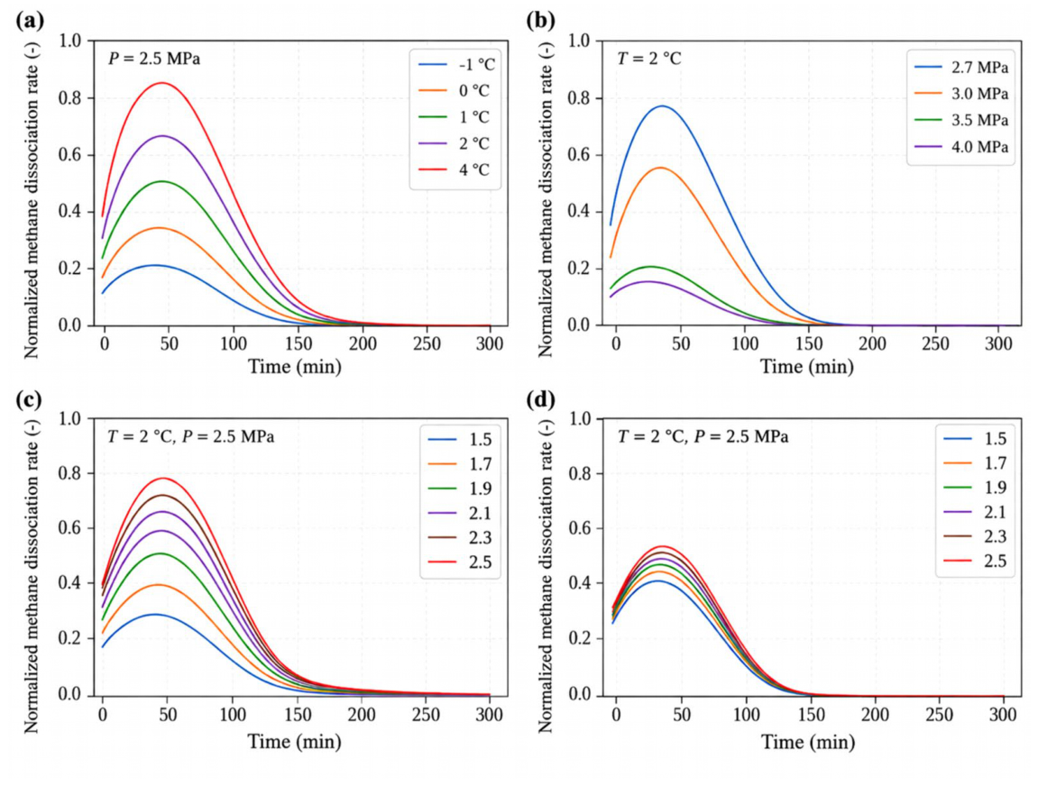
Experimental data were processed using the measured solid-mass loss, pressure drop, permeability, released gas volume, and other recorded parameters. Chemical-removal performance was quantified using the solid-mass loss rate, RA, defined in Section 2.2. For the hydrate-dissociation experiments, the liquid- and gas-flow settings correspond to volumetric flow rates in m3/h. For the hydrate-dissociation experiments, the cumulative gas-release volumes reported in Figure 2 were used for quantitative comparison among the different operating conditions. The dissociation-rate curves presented in Figure 3 were normalized using the common reference basis adopted during the original experimental data processing to facilitate comparison of their relative temporal evolution under different operating conditions. Because the explicit normalization denominator was not retained in the available experimental records, the normalized values are used only to compare the relative magnitude and temporal characteristics of the dissociation response and are not interpreted as absolute dissociation rates.
Figure 2.
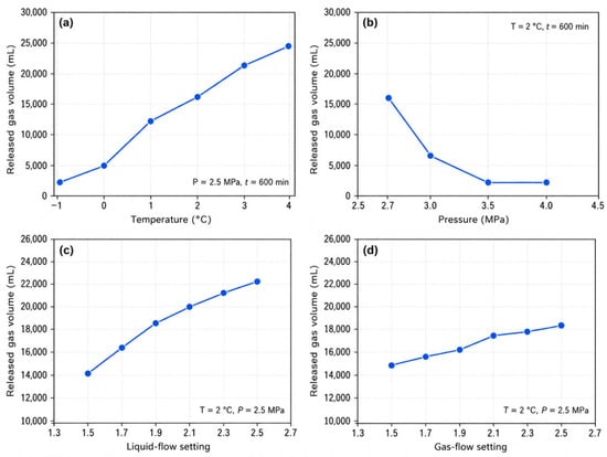
Effects of operating conditions on cumulative methane release during hydrate dissociation: (a) temperature at 2.5 MPa; (b) pressure at 2 °C; (c) liquid-flow rate at 2 °C and 2.5 MPa; and (d) gas-flow rate at 2 °C and 2.5 MPa.
For the comparison of flow-capacity restoration before and after treatment, the pressure-drop reduction ratio, R∆p, was calculated as
where ∆P0 and ∆Pt are the pressure drops across the SCS before and after treatment, respectively. This metric was used for the comparison of physical-only, chemical-only, and physical–chemical composite treatments. The plug-removal efficiencies reported for the standalone HPWJ parameter-screening experiments were retained according to the original experimental evaluation records and were not recalculated from the pressure-drop reduction ratio. Therefore, the HPWJ plug-removal efficiency obtained from the standalone parameter-screening experiments and the pressure-drop reduction ratio, R∆p, reported for the comparative treatment tests represent two distinct evaluation indices.
Figure 3.
Temporal evolution of the normalized methane hydrate dissociation rate under different operating conditions: (a) temperature; (b) pressure; (c) liquid-flow rate; and (d) gas-flow rate.
3. Results
3.1. Mineralogical Characteristics of the Reservoir and Plugging Layer
Bulk-mineral XRD analysis revealed clear compositional differences between the original sediment and the plugging layer retained at the SCS (Table 1). The original sediment contained approximately 36.4 wt.% clay minerals, 25.6 wt.% quartz, 24.3 wt.% calcite, 8.1 wt.% Na-feldspar, 3.3 wt.% K-feldspar, and 2.3 wt.% halite. In comparison, the plugging layer contained approximately 41.5 wt.% clay minerals, representing an increase of about 5.1 percentage points relative to the original sediment. Meanwhile, the quartz content decreased to approximately 22.1 wt.% and the Na-feldspar content decreased to approximately 6.1 wt.%, whereas the average calcite and halite contents remained relatively stable. K-feldspar exhibited greater variability among the plugging-layer samples, with an average content of approximately 3.9 wt.%. These results indicate the preferential enrichment of clay-rich fine particles and redistribution of framework minerals during particle migration and retention near the SCS.
Table 1.
Average bulk-mineral compositions of the original sediment and SCS plugging layer determined by XRD (wt.%).
Clay-mineral analysis further demonstrated substantial differences between the hydrate-bearing sediment and the plugging layer (Table 2). The hydrate-bearing sediment was characterized by relatively low montmorillonite contents of 4–6% and comparatively high illite contents of 29–33%. The I/S mixed-layer minerals were predominantly characterized by a disordered structure, with the reported disordered I/S ratio ranging from 56% to 64%. In contrast, the plugging layer contained 8–11% montmorillonite and 22–25% illite, while the ordered I/S ratio increased to 55–60% and the disordered I/S ratio decreased to 40–45%. Kaolinite showed a slight increase from approximately 5–7% to 6–8%, whereas chlorite remained within a relatively narrow range of approximately 9–11%.
Table 2.
Clay-mineral characteristics of hydrate-bearing sediment and SCS plugging-layer samples (%).
The enrichment of montmorillonite together with the change in I/S structural characteristics indicates pronounced redistribution of clay minerals during the formation of the plugging layer. Compared with the original sediment, the plugging layer contained a larger proportion of clay-rich fine particles, which provides more material for pore filling, particle accumulation, and bridging within the screen structure. Meanwhile, calcite and other framework minerals remained present in the plugging material, indicating that the plug was compositionally heterogeneous rather than being formed by a single mineral component. These mineralogical characteristics provide an important basis for understanding the progressive development of SCS plugging and for the subsequent selection of mineral-responsive chemical plug-removal agents.
3.2. Hydrate Dissociation Behavior and Stability
Methane hydrate stability was evaluated by examining the effects of temperature, pressure, and fluid-flow conditions on cumulative gas release during dissociation. Figure 2 summarizes the released-gas volumes measured after 600 min under the different experimental conditions. At a constant pressure of 2.5 MPa, increasing the dissociation temperature from −1 to 4 °C resulted in a pronounced increase in cumulative gas release from 2305 to 24,452 mL (Figure 2a). The corresponding released-gas volumes at 0, 1, 2, and 3 °C were 4982, 12,351, 16,325, and 21,258 mL, respectively. The monotonic increase in gas release demonstrates that increasing temperature strongly promoted hydrate dissociation and reduced the apparent stability of methane hydrate under the tested pressure condition.
Pressure produced the opposite response. At a constant temperature of 2 °C, cumulative gas release decreased sharply as the dissociation pressure increased from 2.7 to 4.0 MPa (Figure 2b). The released-gas volume decreased from 15,820 mL at 2.7 MPa to 6561 mL at 3.0 MPa and further to 2342 and 2319 mL at 3.5 and 4.0 MPa, respectively. The substantial reduction between 2.7 and 3.5 MPa indicates the strong suppression of hydrate dissociation with increasing pressure, whereas the comparatively small difference between 3.5 and 4.0 MPa suggests that the stabilizing influence of further pressure increase became less pronounced within the higher-pressure range.
Fluid-flow disturbance also affected hydrate dissociation under otherwise identical temperature and pressure conditions. When the gas-flow rate was maintained at 1.8 m3/h, increasing the liquid-flow rate from 1.5 to 2.5 m3/h increased the cumulative released-gas volume from 14,201 to 22,297 mL (Figure 2c). The intermediate values at liquid-flow rates of 1.7, 1.9, 2.1, and 2.3 were 16,325, 18,625, 20,126, and 21,332 mL, respectively. Although gas release increased continuously, the incremental increase became smaller at the higher liquid-flow rates, indicating a diminishing enhancement of hydrate dissociation as liquid-flow disturbance was further increased.
A similar but weaker dependence was observed for the gas-flow rate (Figure 2d). At a constant liquid-flow rate of 2.0 m3/h, the cumulative released-gas volume increased from 15,022 mL at a gas-flow rate of 1.5 to 18,466 mL at 2.5. The corresponding released-gas volumes at settings of 1.7, 1.9, 2.1, and 2.3 were 15,789, 16,325, 17,632, and 17,891 mL, respectively. Over the same tested setting range, the variation induced by liquid flow was greater than that induced by gas flow, indicating a stronger response of hydrate dissociation to liquid-flow disturbance under the present experimental conditions.
Figure 2 characterizes the cumulative methane release over the full 600 min experimental period, whereas Figure 3 is used to compare the temporal evolution of the normalized dissociation-rate response. Although the normalized dissociation rate decreased to a relatively low level after approximately 150 min under most tested conditions, gas release did not necessarily cease completely. The experiments were therefore continued to 600 min to capture the subsequent low-rate gas release and to provide a common endpoint for comparing cumulative methane release among the different operating conditions.
In addition to the cumulative gas-release response, the normalized dissociation-rate curves exhibited a clear time-dependent evolution (Figure 3). Under different temperature conditions, the dissociation response increased rapidly during the early stage, reached a maximum, and then gradually decreased. Higher temperatures produced stronger normalized dissociation responses, consistent with the cumulative gas-release results shown in Figure 2a. Under different pressure conditions, lower pressures produced stronger early-stage responses, whereas increasing pressure suppressed the dissociation process (Figure 3b), consistent with the greater hydrate stability observed at elevated pressure.
Changes in fluid-flow conditions mainly affected the magnitude and duration of the normalized dissociation response. Increasing the liquid-flow rate enhanced the early-stage response and prolonged the effective gas-release process, while the differences became smaller at the higher settings (Figure 3c). Increasing the gas-flow rate produced the same general tendency, although the separation among the individual curves was smaller than that observed for liquid flow (Figure 3d). These trends are consistent with the cumulative gas-release results in Figure 2, indicating that fluid-flow disturbance promoted methane hydrate dissociation under the investigated conditions.
Overall, the hydrate dissociation experiments demonstrate that temperature, pressure, and fluid-flow disturbance jointly affect methane hydrate stability. Within the investigated ranges, increasing temperature promoted hydrate dissociation, whereas increasing pressure suppressed gas release and enhanced hydrate stability. Increasing liquid- and gas-flow disturbances also promoted methane release, although the response to liquid-flow variation was more pronounced under the tested conditions. These results provide an experimental basis for considering hydrate phase behavior in the subsequent interpretation of SCS plugging. Local variations in temperature, pressure, and flow conditions during production may alter hydrate stability in and around the plugging region; however, the present dissociation experiments alone do not directly quantify secondary-hydrate formation within the SCS plugging layer.
3.3. Long-Term Plugging Mechanism and Evolution
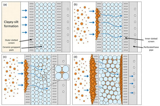
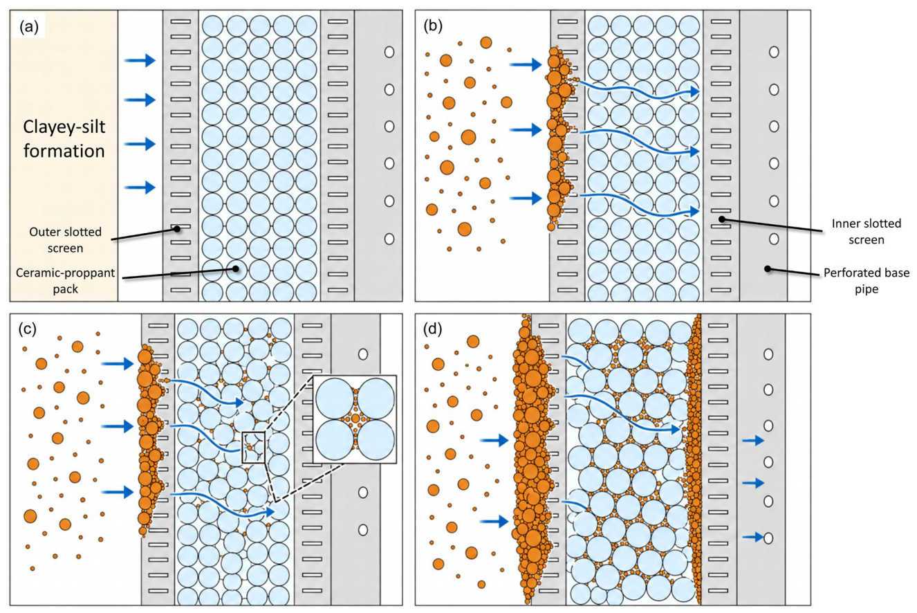
The plugging behavior of the pre-packed composite SCS was analyzed using CFD–DEM simulation together with long-period plugging experiments, and the progressive plugging process is schematically summarized in Figure 4. As shown schematically in Figure 4a, the screen system consisted of an outer slotted screen, a ceramic-proppant pack, an inner slotted screen, and a perforated base pipe, with particle migration occurring from the clayey-silt formation toward the inner flow channel. Under the imposed flow conditions, relatively coarse particles were first retained at the outer slotted screen and formed localized bridging structures (Figure 4b). Fine particles subsequently passed through the remaining openings, invaded the ceramic-proppant pack, and accumulated within the intergranular pore throats (Figure 4c). With continued particle loading, the retained particles extended further inward and gradually developed into a more continuous plugging structure spanning the outer screen, packing layer, and inner screen region (Figure 4d). These observations indicate that plugging followed a progressive outside-to-inside pathway rather than being restricted to surface deposition at the outer screen.
Figure 4.
Schematic representation of progressive particle migration and plugging development within the pre-packed composite SCS based on CFD–DEM analysis and long-period experimental observations: (a) configuration of the clayey-silt formation and pre-packed composite screen structure; (b) initial particle retention and bridging at the outer slotted screen; (c) fine-particle invasion and pore-throat retention within the ceramic-proppant pack; and (d) developed outside-to-inside composite plugging structure Blue arrows and lines indicate the fluid-flow and particle-migration directions; orange circles represent clayey-silt particles, light-blue circles represent ceramic proppant, and gray regions represent the screen and base-pipe components.
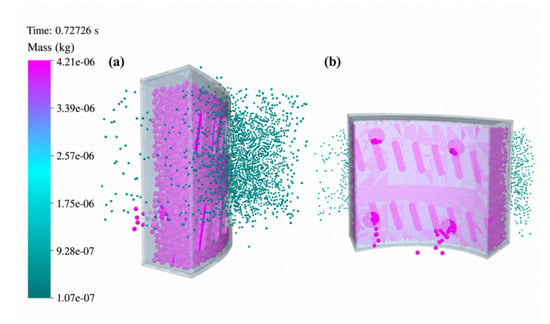
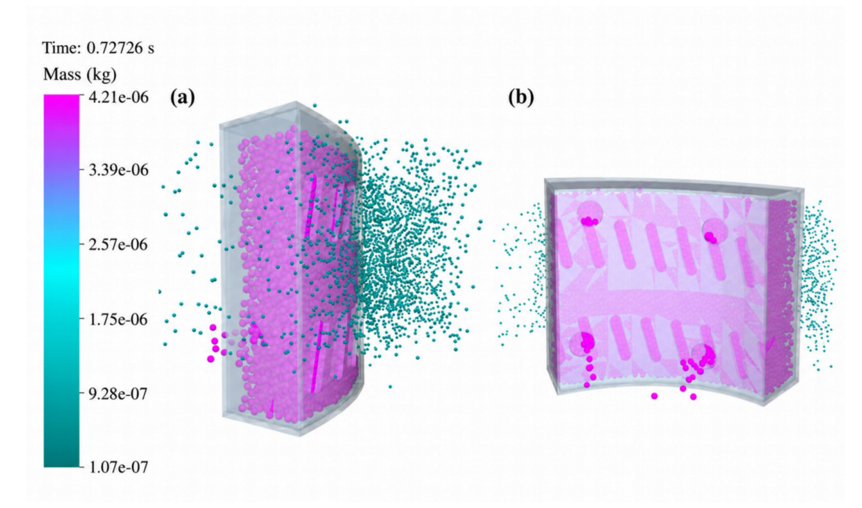
Representative CFD–DEM particle-distribution results are shown in Figure 5. The side-view simulation indicates that particles initially accumulate near the outer region of the SCS and progressively concentrate toward the outer slotted-screen openings. The localized particle enrichment near the slot entrances indicates preferential retention and the development of initial bridging structures. The corresponding front-view result further shows that particle retention is not restricted to the outer screen surface. A fraction of the finer particles penetrates into the ceramic-proppant pack through the remaining flow passages and forms discrete particle-rich zones near the internal openings and intergranular pore-throat regions. These numerical results provide direct visual evidence for the progressive redistribution of particles from the outer screen toward the internal packing layer and support the outside-to-inside plugging mechanism illustrated in Figure 4. To further quantify the particle-retention behavior, the particle distribution was evaluated according to the relative particle accumulation regions within the SCS structure. The highest particle concentration occurred near the outer slotted screen, while a lower but continuous particle population penetrated into the ceramic-proppant packing layer, confirming the gradual transition from surface bridging to internal pore-throat retention.
Figure 5.
Representative CFD–DEM particle-distribution results during SCS plugging: (a) side view showing particle migration and accumulation near the outer slotted screen; (b) front view showing particle penetration and localized retention within the internal screen structure.
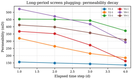
The long-period plugging experiments showed a corresponding deterioration in the hydraulic performance of the SCS. Representative experimental data are summarized in Table 3, and the temporal permeability evolution of selected test groups is plotted in Figure 6. In all selected tests, permeability decreased continuously with plugging time, although the degree of decline differed among the individual groups. For example, the permeability of Y2-1 decreased from 320 mD on Day 1 to 185 mD on Day 4, whereas Y8-1 decreased from 523 to 293 mD over the same period. Y4-1 exhibited a more pronounced reduction from 368 to 163 mD, while Y1-1 showed a relatively moderate decline from 156 to 135 mD. These results consistently demonstrate that continued particle accumulation progressively reduced the flow capacity of the SCS.
Table 3.
Representative permeability, pressure-drop, and sand-concentration data during long-period SCS plugging experiments.
Figure 6.
Evolution of permeability during selected long-period SCS plugging tests, showing progressive deterioration in screen flow capacity.
The measured pressure-drop data in Table 3 further support the plugging evolution inferred from the permeability results. As permeability decreased, the pressure drop across the SCS increased correspondingly. For example, the pressure drop of Y2-1 increased from 0.29 MPa on Day 1 to 0.71 MPa on Day 4, and that of Y4-1 increased from 0.23 to 0.59 MPa. Similar increasing trends were also observed in Y8-1 and Y9-1. The simultaneous decrease in permeability and increase in pressure drop indicate progressive hydraulic deterioration of the plugging screen under long-term particle loading.
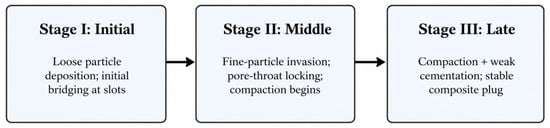
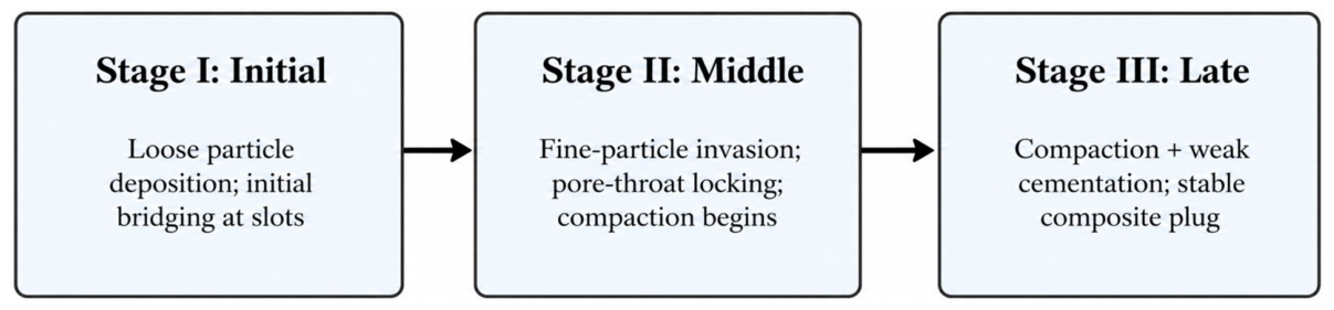
Based on the combined numerical and experimental results, the plugging evolution can be divided into three representative stages, as summarized in Figure 7. During Stage I (initial), plugging was dominated by loose particle deposition and localized bridging at the outer slotted screen. At this stage, the plugging structure remained relatively discontinuous and the internal pore space was only moderately affected. During Stage II (middle), fine particles continuously invaded the ceramic-proppant pack and accumulated in the pore throats, leading to pore-throat locking and the onset of compaction. Effective flow channels became progressively narrower, and the hydraulic resistance increased more noticeably. During Stage III (late), continued deposition and rearrangement caused the retained particles to form a more stable composite plugging structure. At this stage, compaction became more pronounced and local weak cementation was observed, further reducing pore connectivity and stabilizing the plug.
Figure 7.
Schematic three-stage evolution of SCS plugging: Stage I, loose particle deposition and initial bridging at the outer slots; Stage II, fine-particle invasion, pore-throat locking, and onset of compaction; and Stage III, compaction with weak cementation and formation of a stable composite plug.
Overall, the combined CFD–DEM and long-period plugging results demonstrate that SCS plugging is a progressive process involving particle retention, bridging, internal invasion, pore-throat locking, and compaction. The plugging structure evolves from an initially loose deposit into a more stable and compact composite plug, leading to continuous deterioration in screen flow capacity. This stage-wise understanding provides the physical basis for distinguishing representative plugging stages and for evaluating the subsequent plug-removal behavior.
3.4. Mineral-Selective Dissolution Characteristics of the Plugging Layer
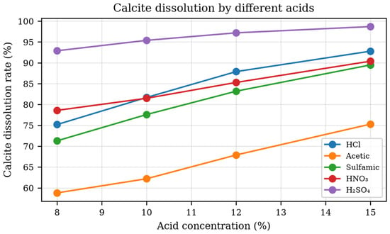
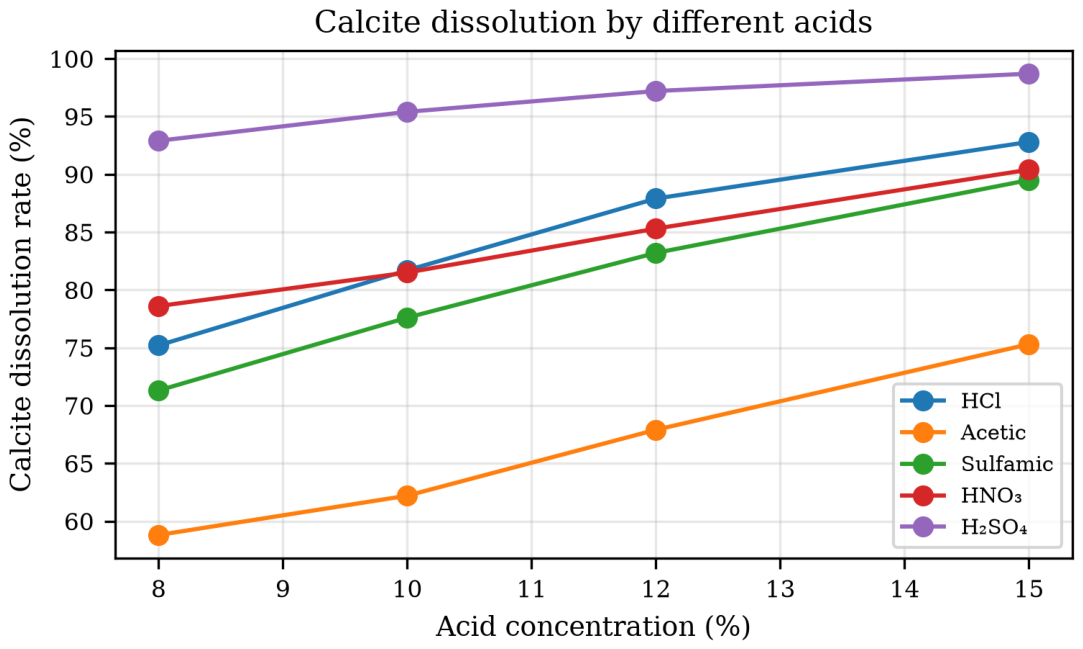
The mineralogical heterogeneity identified in Section 3.1 requires chemical treatments capable of targeting different components of the plugging structure. Calcite showed a strong response to acidic treatment, although the dissolution efficiency depended substantially on both acid type and concentration. As shown in Figure 8, calcite dissolution generally increased with acid concentration over the investigated range. At an acid concentration of 12%, the dissolution rates obtained with HCl, acetic acid, sulfamic acid, HNO3, and H2SO4 were 87.9%, 67.9%, 83.2%, 85.3%, and 97.2%, respectively. HCl therefore provided a high dissolution efficiency for the carbonate component, whereas acetic acid exhibited a distinctly weaker response under comparable conditions. Although H2SO4 produced the highest calcite dissolution, its use is unfavorable because the reaction can generate poorly soluble CaSO4 and thereby introduce a risk of secondary precipitation. These results indicate that dissolution efficiency alone is insufficient for selecting an acid system for SCS plug removal.
Figure 8.
Effect of acid type and concentration on calcite dissolution.
In contrast to the carbonate-selective response of conventional acids, HF exhibited substantially greater activity toward silicate and clay minerals. As summarized in Table 4, increasing the HF concentration from 2% to 4% increased the dissolution of all representative silicate minerals. At 4% HF, the dissolution rates of quartz, K-feldspar, plagioclase, montmorillonite, and kaolinite were 15.3%, 44.6%, 53.8%, 63.1%, and 84.2%, respectively. Kaolinite and montmorillonite therefore showed markedly higher responses than feldspars, whereas quartz remained the least reactive component. The experimental results demonstrate an overall mineral-selective tendency in which clay minerals were more susceptible to HF treatment than feldspars and quartz. This selectivity is particularly relevant to the plugging layer because the XRD results in Section 3.1 showed the enrichment of clay-rich fine particles within the SCS. This preferential reactivity toward clay minerals is particularly important for SCS cleaning because the plugging layer was enriched in clay-rich fines, which contributed directly to pore filling and pore-throat locking.
Table 4.
Dissolution of representative silicate and clay minerals by HF solutions.
The complementary responses of HCl and HF provide the basis for using an HCl–HF mud-acid system to treat the multi-mineral plugging layer. Single-mineral tests showed that the combined acid maintained strong calcite dissolution while extending the reactive range toward feldspar and clay minerals. For example, 12% HCl + 2% HF produced dissolution rates of 49.8% for plagioclase, 59.4% for montmorillonite, and 55.8% for chlorite, while increasing the HF concentration to 4% further enhanced the dissolution of plagioclase and montmorillonite. These results confirm the complementary roles of HCl and HF in attacking carbonate and silicate/clay components of the plugging material.
Tests using complete formulated sediment and field-collected deep-sea mud further showed that increasing HCl concentration did not continuously improve the overall removal performance of the mud-acid system. Among the tested formulations, 10% HCl + 2% HF achieved the highest solid-mass loss rates, reaching 65.4% for the formulated sediment and 63.8% for the deep-sea mud. The corresponding values decreased to 62.4% and 61.0% for 12% HCl + 2% HF and to 61.3% and 59.2% for 15% HCl + 2% HF. This non-monotonic response indicates that increasing HCl concentration beyond 10% did not proportionally improve removal of the heterogeneous plugging material because the overall treatment efficiency depended on the combined response of carbonate, silicate, and clay components rather than carbonate dissolution alone. Therefore, 10% HCl + 2% HF was selected as the core mud-acid formulation for the subsequent plug-removal experiments.
Overall, the dissolution experiments demonstrate that chemical removal of the plugging layer is governed by mineral-selective reactions rather than the complete dissolution of all solid components. HCl preferentially removes carbonate minerals, whereas HF extends the chemical action toward clay minerals and feldspars. Their combined action progressively weakens the heterogeneous mineral framework and converts the compact plugging material into a more dispersible and mechanically removable state. These results establish 10% HCl + 2% HF as the core acid system and provide the basis for evaluating dispersing, chelating, and hydrate-inhibiting agents in the following section.
3.5. Screening of Chemical Plug-Removal Agents
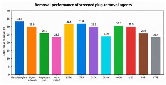
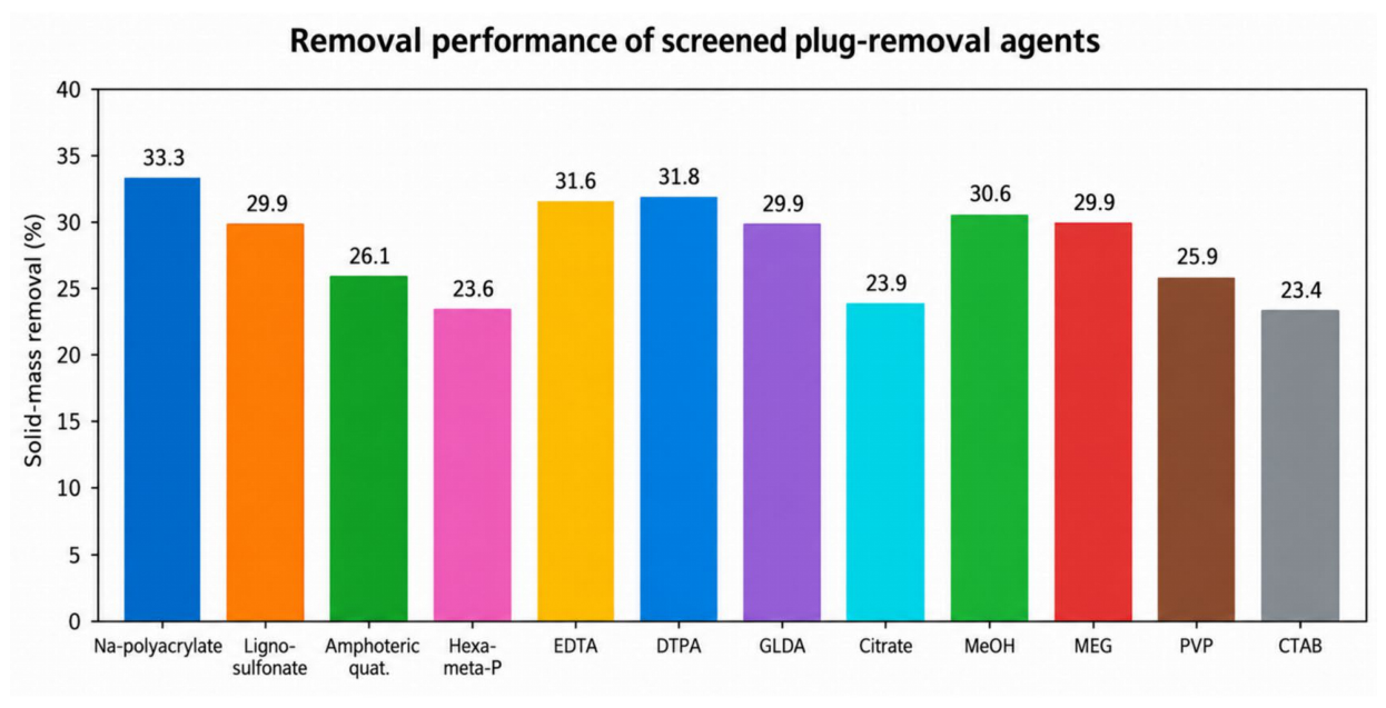
Following the selection of the HCl–HF mud-acid system, auxiliary agents with different functional roles were further screened using deep-sea mud. These agents were classified mainly as clay dispersants, chelating agents, and hydrate inhibitors. As summarized in Table 5 and Figure 9, PAAS and lignosulfonate exhibited relatively high removal among the dispersing agents, indicating their effectiveness in weakening clay-particle aggregation. Polyacrylate-based polymers are widely used to regulate clay-particle dispersion and suspension behavior in aqueous drilling-fluid systems [24]. Among the chelating agents, DTPA and EDTA showed stronger removal than GLDA and sodium citrate, consistent with their ability to weaken metal-ion-mediated bridging [25]. MeOH and MEG also produced appreciable solid-mass removal while providing an additional hydrate-inhibition function [18,19], whereas PVP and CTAB showed relatively milder responses. At the selected concentrations, sodium polyacrylate showed the highest solid-mass removal among the dispersants (33.3%), while DTPA and EDTA reached 31.8% and 31.6%, respectively. MeOH and MEG produced solid-mass removals of 30.6% and 29.9%, respectively. Overall, the single-agent tests demonstrate that different additives target different components or stabilization mechanisms of the heterogeneous plugging material.
Table 5.
Selected concentrations and solid-mass removal of chemical plug-removal agents on deep-sea mud.
Figure 9.
Solid-mass removal of all screened plug-removal agents at selected concentrations on deep-sea mud.
Based on the single-agent screening, representative functional components were subsequently incorporated into the acid system. As shown in Table 6, the 12% HCl + 2% HF reference system produced approximately 61.0% removal, whereas the incorporation of additional functional components increased the removal to 64.4% for the dispersant-containing system, 69.9% for the EDTA-containing system, and 68.1% for the MEG-containing system. The concentrations listed in Table 5 represent the selected conditions for the single-agent screening tests. In the composite acid systems, EDTA and MEG were instead introduced at 1 wt.% as auxiliary components rather than at their single-agent screening concentrations. These lower auxiliary dosages were used to evaluate their incremental effects within the HCl–HF acid matrix; therefore, the concentrations used in the single-agent and composite tests should not be interpreted as directly matched conditions. The EDTA-containing formulation exhibited the highest short-term removal, while the MEG-containing formulation maintained a similarly high removal capacity and simultaneously introduced hydrate-inhibition functionality. These results show that the performance of the chemical treatment can be improved by combining mineral dissolution with dispersion, chelation, or hydrate inhibition. The composite-agent screening was conducted as a separate formulation-comparison series using 12% HCl + 2% HF as a common acid reference condition.
Table 6.
Solid-mass removal of representative composite chemical systems on deep-sea mud.
Overall, the screening results indicate that an effective chemical plug-removal system for clayey-silt gas hydrate reservoirs should integrate multiple functions rather than rely on acid dissolution alone. The mud-acid system provides the primary mineral-removal capability, while dispersing and chelating agents weaken particle aggregation and mineral-ion bridging, and hydrate inhibitors help reduce the risk of hydrate re-formation after flow channels are reopened. The chemical treatment therefore primarily serves to weaken and loosen the compact plugging structure, providing a more favorable condition for the subsequent high-pressure water-jet removal process.
3.6. Physical Plug Removal by High-Pressure Water Jet
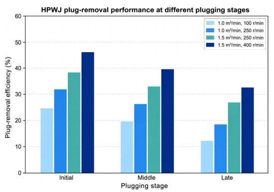
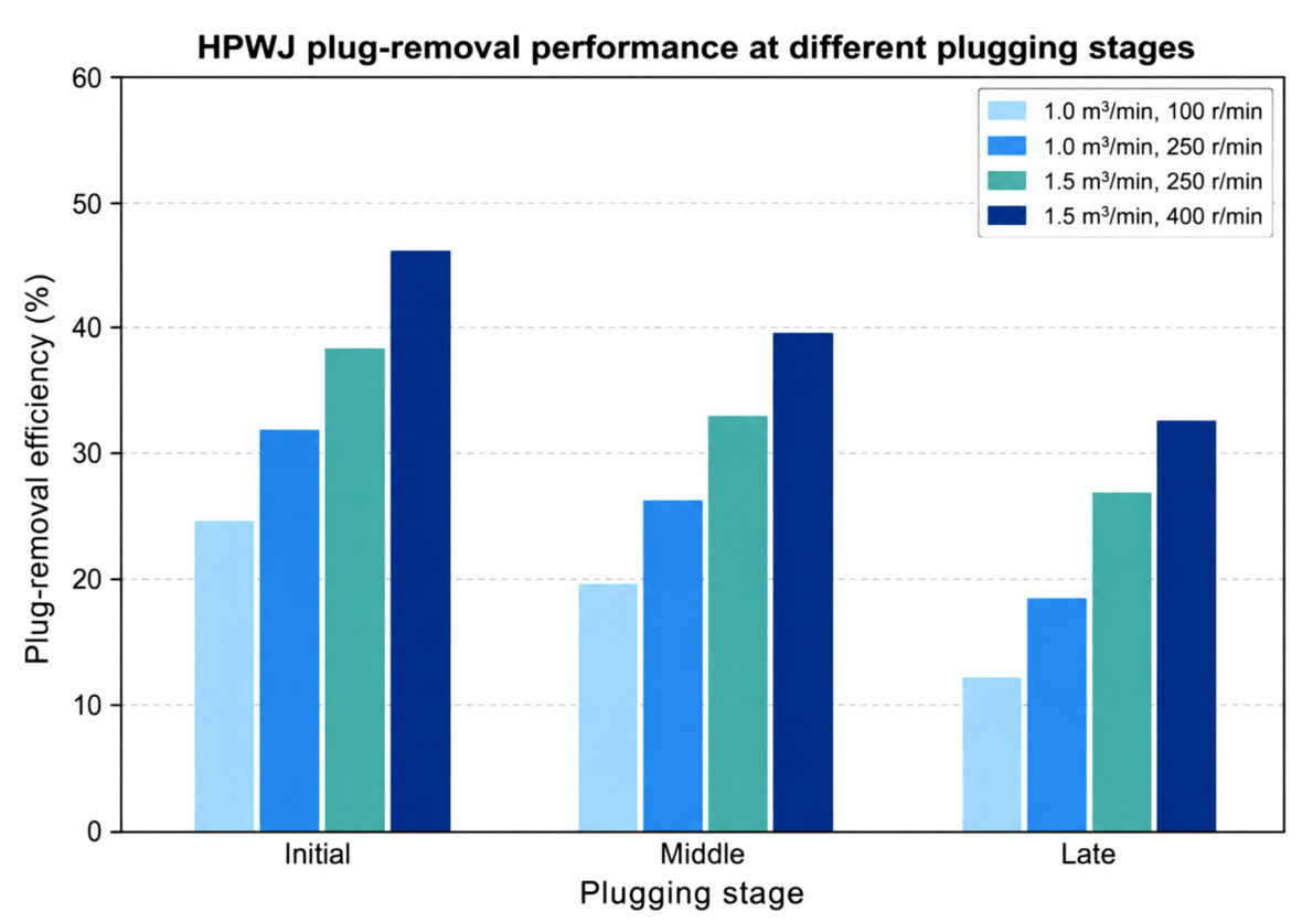
High-pressure water jetting (HPWJ) with a self-excited oscillation (SEO) nozzle assembly exhibited a clear dependence on both operating conditions and plugging stage. The jetting tool was equipped with 24 helically arranged SEO nozzles, each with a minimum outlet diameter of 4 mm and a discharge coefficient, Cd, of 0.90. As summarized in Table 7 and Figure 10, the plug-removal efficiency increased consistently with increasing pump rate and nozzle rotation speed. Under the lowest-energy condition of 1.0 m3/min and 100 r/min, the removal efficiencies were 24.6%, 19.8%, and 12.4% for the initial, middle, and late plugging stages, respectively. Increasing the rotation speed to 250 r/min increased the corresponding efficiencies to 31.7%, 26.3%, and 18.6%. When the pump rate was further increased to 1.5 m3/min at 250 r/min, the efficiencies reached 38.4%, 33.1%, and 26.8%, demonstrating that both flow rate and circumferential jet coverage contributed to improved physical removal.
Table 7.
Plug-removal efficiency of HPWJ under different operating conditions and plugging stages.
Figure 10.
Effect of HPWJ operating conditions on plug-removal efficiency at different SCS plugging stages.
The plug-removal efficiencies reported in Table 7 correspond to the stage-specific HPWJ evaluation index used in the original physical-removal experiments and are distinct from the pressure-drop reduction ratio R∆p defined in Section 2.6.
At the highest tested operating condition of 1.5 m3/min and 400 r/min, the removal efficiency increased to 46.2% for the initial stage, 39.6% for the middle stage, and 32.5% for the late stage. The increase in pump rate from 1.0 to 1.5 m3/min was accompanied by an increase in the reported maximum nozzle velocity from 55.2 to 82.9 m/s, while higher rotation speed increased the circumferential coverage of the jet. The enhanced hydraulic loading therefore improved the impact, shear, and stripping action on the plugging material. Nevertheless, under every operating condition, the removal efficiency followed the same order of initial > middle > late, indicating that the progressively compacted plugging structure became increasingly resistant to direct mechanical removal.
The solids discharged during HPWJ treatment were collected and quantified; however, the particle-size distribution of the stripped debris was not measured in the present test series. Therefore, the physical-removal mechanism discussed here is evaluated primarily from the hydraulic response and recovered solids rather than from direct fragment-size characterization. Despite the improved performance at higher jet energy, HPWJ alone removed only 32.5% of the late-stage plug under the highest tested condition. This result is consistent with the plugging evolution identified in Section 3.3: loose deposits formed during the initial stage can be readily detached by hydraulic impact, whereas pore-throat locking, compaction, and weak cementation developed during the middle and late stages increasingly restrict mechanical stripping. HPWJ is therefore effective as a physical removal method, particularly for early-stage maintenance, but its limited ability to remove compacted plugs provides the motivation for combining chemical weakening with subsequent mechanical stripping in the physical–chemical composite treatment discussed in Section 3.7.
3.7. Performance of Physical–Chemical Composite Plug Removal
The physical–chemical composite treatment, consisting of chemical pretreatment followed by HPWJ stripping, achieved substantially greater flow-capacity restoration than either treatment applied alone. For the composite tests, the HPWJ treatment durations were provisionally set at 5, 8, and 10 min for the initial, middle, and late plugging stages, respectively, with longer jetting applied to the more compact plugs. As summarized in Table 8, the pressure-drop reduction ratio ranged from 74.1% to 78.0% during the initial plugging stage and from 64.6% to 69.6% during the middle stage. The highest performance was obtained for the late-stage plug, for which the pressure-drop reduction ratio remained between 85.1% and 85.6% across the three repeated tests. The corresponding mean efficiencies were approximately 75.7%, 67.7%, and 85.3% for the initial, middle, and late stages, respectively.
Table 8.
Pressure-drop reduction ratio of the physical–chemical composite treatment at different SCS plugging stages.
The pressure-drop reduction ratio is used here as an indicator of hydraulic flow-capacity restoration and should not be interpreted as a direct measurement of the fraction of solid plugging material physically removed.
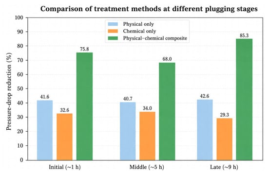
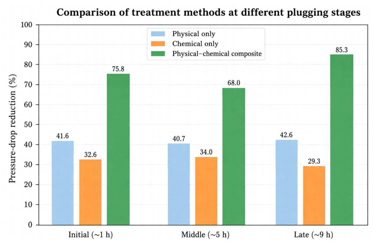
A consistent comparison based on the reduction in screen pressure drop further demonstrates the advantage of the composite treatment (Figure 11). Using the same pre- and post-treatment pressure-drop data, the average pressure-drop reductions for the physical-only, chemical-only, and composite treatments were approximately 41.6%, 32.6%, and 75.8% at the initial stage; 40.7%, 34.0%, and 68.0% at the middle stage; and 42.6%, 29.3%, and 85.3% at the late stage, respectively. Thus, the composite procedure produced the largest pressure-drop recovery at all three stages. In particular, its advantage became most pronounced for the late-stage plug, despite the greater degree of compaction and structural stabilization.
Figure 11.
Comparison of pressure-drop reduction achieved by physical-only, chemical-only, and physical–chemical composite treatments at different SCS plugging stages.
The non-monotonic stage dependence is interpreted in terms of the evolving plug structure. During the middle stage, fine-particle invasion and pore-throat locking produce a compact structure that restricts both chemical penetration and direct hydraulic stripping, resulting in the lowest composite response. At the late stage, although the plug is more compact, the development of continuous weakly cemented contacts provides chemically susceptible bonding sites. Chemical pretreatment can therefore produce a more pronounced loss of structural integrity before HPWJ stripping, which is consistent with the higher pressure-drop recovery observed at this stage.
The enhanced performance of the composite treatment is consistent with a sequential chemical weakening–mechanical stripping process. Chemical pretreatment first penetrates the plugging layer and weakens mineral bonding and particle contacts, thereby reducing the structural resistance of the compact plug. The subsequent HPWJ then applies pulsed impact and shear to detach, fragment, and transport the loosened material. This combined action is particularly effective for late-stage plugging, where compaction and weak cementation limit the effectiveness of either physical or chemical treatment alone. The results therefore demonstrate that chemical pretreatment primarily acts as a structural-weakening step, while HPWJ provides the mechanical removal required to reopen the blocked flow channels.
4. Discussion
4.1. Progressive Plugging Mechanism of the SCS
The results indicate that SCS plugging in clayey-silt gas hydrate reservoirs is a progressive process rather than simple surface deposition. Clay-rich fine particles were preferentially retained within the screen, while CFD–DEM and long-period experiments revealed an outside-to-inside evolution from outer-screen bridging to pore-throat retention and subsequent compaction. This structural development explains the continuous permeability decline and pressure-drop increase during prolonged particle loading. Hydrate phase behavior may further influence local plugging because hydrate stability is sensitive to temperature, pressure, and flow conditions; however, secondary hydrate formation within the plugging layer was not directly quantified in the present experiments. The CFD–DEM results should therefore be interpreted primarily as evidence of hydrodynamically driven particle migration, retention, bridging, and redistribution. The present numerical model does not explicitly resolve clay swelling and dispersion, mineral dissolution or cementation, or secondary hydrate nucleation and growth. These physicochemical processes were instead evaluated through the accompanying mineralogical, hydrate-dissociation, and long-period experimental results.
4.2. Implications of Mineral-Selective Chemical Removal
The heterogeneous plugging layer requires a chemical system capable of targeting different mineral components. HCl preferentially removed carbonate minerals, whereas HF showed greater activity toward clay minerals and feldspars. Their combination therefore weakened a broader range of plugging components than either acid alone. The preferential response of clay minerals to HF is particularly relevant because the plugging layer was enriched in clay-rich fines, which contributed to pore filling and pore-throat locking. HCl mainly removed carbonate components, whereas HF extended the chemical action toward clay minerals and feldspars, thereby broadening the range of weakened plugging components. The complete-sediment tests further showed that increasing acid concentration did not necessarily improve overall removal, with 10% HCl + 2% HF providing the best performance among the tested formulations. The superior overall performance of 10% HCl + 2% HF indicates that plug removal was governed by the response of the heterogeneous mineral assemblage rather than by HCl concentration alone; further increasing HCl concentration enhanced carbonate reactivity but did not proportionally improve removal of the silicate- and clay-rich fractions. Dispersing, chelating, and hydrate-inhibiting agents further enhanced the treatment by weakening particle aggregation, metal-ion bridging, and potential hydrate re-formation. These trends are consistent with recent studies showing that polymeric dispersants, chelating agents, and hydrate inhibitors can improve particle dispersion, metal-ion complexation, and hydrate control in wellbore-fluid systems.
4.3. Mechanism and Stage Dependence of the Physical–Chemical Composite Treatment
The higher pressure-drop recovery obtained by the composite treatment can be attributed to a sequential chemical weakening–mechanical stripping process. Chemical pretreatment reduces mineral bonding and loosens the compact plugging structure, after which HPWJ provides the impact and shear required to detach and transport the weakened material. This mechanism also explains the stage dependence of removal performance. Early-stage deposits can be partly removed by water jetting alone, whereas compact middle- and late-stage plugs benefit more strongly from prior chemical weakening. The stage dependence of the composite treatment can be related to the evolving plugging structure. During the middle stage, fine-particle invasion and pore-throat locking produced dispersed internal blockage, restricting both chemical penetration and hydraulic access and resulting in the lowest composite pressure-drop reduction (~68.0%). In the late stage, continued compaction and weak cementation produced a more continuous plug structure. Chemical pretreatment weakened these contacts before jetting, allowing the subsequent HPWJ to detach larger portions of the loosened plug and increasing the pressure-drop reduction to approximately 85.3%. This interpretation explains the non-monotonic recovery response without implying a mathematically proven synergistic effect.
4.4. Engineering Implications, Limitations, and Outlook
The results suggest that plug-removal strategies should be adjusted according to plugging severity: physical cleaning may be sufficient for early maintenance, whereas middle- and late-stage plugging requires chemical pretreatment followed by HPWJ. Nevertheless, the present experiments were conducted under controlled laboratory conditions, and further validation under realistic temperature, pressure, multiphase-flow, and particle-loading conditions is required. The corrosion compatibility of the HCl–HF system with actual SCS materials was not evaluated in this study. Because strong-acid formulations may cause the corrosion of metallic screen and downhole components, the present chemical system should be regarded as a bench-scale plug-weakening formulation rather than a field-ready treatment fluid. Before field application, representative screen materials should be tested under the actual acid concentration, temperature, pressure, and exposure time, with appropriate corrosion-control measures incorporated and the project corrosion-rate criterion of <0.076 mm/year experimentally verified.
The plugging-fluid chemistry was also not systematically varied. Residual drilling-fluid components, clay stabilizers, salinity, and hydrate inhibitors may alter clay dispersion, interparticle interactions, and hydrate stability and should therefore be evaluated in future work. Future studies should further optimize chemical dosage, soaking time, HPWJ operating parameters, and treatment duration and verify the proposed procedure using larger-scale SCS sections under representative temperature–pressure–multiphase-flow conditions.
5. Conclusions
This study investigated the progressive plugging behavior of pre-packed composite sand-control screens (SCSs) in clayey-silt gas hydrate reservoirs and evaluated a physical–chemical composite plug-removal strategy. The main conclusions are as follows:
- (1)
- SCS plugging develops progressively from the outside to the inside. Clay-rich fine particles are preferentially retained within the screen structure, and the plugging process evolves from outer-screen bridging to fine-particle invasion, pore-throat locking, and subsequent compaction. Representative CFD–DEM particle-distribution results further showed localized particle accumulation near the outer slotted screen and continued penetration of fine particles into the ceramic-proppant pack, providing direct numerical visualization of the progressive outside-to-inside retention process. This structural evolution is accompanied by decreasing permeability and increasing flow resistance.
- (2)
- Methane hydrate dissociation was strongly affected by temperature, pressure, and fluid-flow disturbance. At 2.5 MPa, increasing the temperature from −1 to 4 °C increased the 600 min cumulative gas release from 2305 to 24,452 mL, whereas at 2 °C, increasing the pressure from 2.7 to 4.0 MPa reduced the released gas volume from 15,820 to 2319 mL. Increasing liquid- and gas-flow disturbance also promoted dissociation, with the liquid-flow effect being more pronounced within the investigated range. These results confirm that local thermodynamic and flow conditions can substantially alter hydrate stability around the SCS.
- (3)
- Chemical removal is strongly mineral-selective. HCl primarily targets carbonate components, whereas HF extends the treatment toward clay minerals and feldspars. Among the tested mud-acid formulations, 10% HCl + 2% HF provided the best overall removal performance for both formulated sediment and deep-sea mud and was therefore selected as the core acid system.
- (4)
- HPWJ performance depends strongly on plugging stage and operating conditions. Increasing pump rate and rotation speed improved physical removal, whereas compact middle- and late-stage plugs were more resistant to direct hydraulic stripping. Under the highest tested HPWJ condition, removal efficiency reached 46.2%, 39.6%, and 32.5% for the initial, middle, and late stages, respectively.
- (5)
- Chemical pretreatment followed by HPWJ provided the greatest flow-capacity restoration. The composite treatment achieved mean pressure-drop reductions of approximately 75.7%, 67.7%, and 85.3% for the initial, middle, and late plugging stages, respectively. The non-monotonic stage dependence reflects differences in plug structure: middle-stage pore-throat locking restricts reagent penetration and hydraulic access, whereas chemical weakening of the more continuous late-stage plug enables more effective subsequent mechanical stripping.
Overall, the proposed composite approach provides a practical basis for restoring plugged SCSs in clayey-silt gas hydrate reservoirs. However, the present findings are based on controlled laboratory experiments, and corrosion compatibility, treatment-parameter optimization, and larger-scale validation remain necessary before field application.
Author Contributions
Conceptualization, M.L., B.W. and P.X.; methodology, B.W. and P.X.; validation, B.W., Y.Z., M.L., H.D., Q.H., X.S. and J.L.; formal analysis, B.W. and Y.Z.; investigation, B.W.; resources, M.L., H.D., Q.H., X.S., J.L. and P.X.; data curation, B.W. and Y.Z.; writing—original draft preparation, Y.Z.; writing—review and editing, M.L., H.D., Q.H., X.S., J.L., P.X. and Y.Z.; visualization, Y.Z.; supervision, P.X.; project administration, M.L. and P.X. All authors have read and agreed to the published version of the manuscript.
Funding
This research was funded by the National Key Research and Development Program of China, grant number 2023YFC2811004.
Data Availability Statement
The data supporting the findings of this study are available from the corresponding authors upon reasonable request. The raw experimental records and numerical input files are not publicly archived.
Acknowledgments
The authors gratefully acknowledge the technical assistance provided by the project team and laboratory staff during sample preparation, experimental testing, and data organization.
Conflicts of Interest
Authors Ming Luo, Huan Diao, Qing Huang, Xiangke Shi, and Jiawen Liu were employed by CNOOC Hainan Energy Co., Ltd. Author Bangzhe Wang was employed by China Oilfield Services Limited (COSL). The remaining authors declare that the research was conducted in the absence of any commercial or financial relationships that could be construed as a potential conflict of interest.
References
- Sloan, E.D., Jr.; Koh, C.A. Clathrate Hydrates of Natural Gases, 3rd ed.; CRC Press: Boca Raton, FL, USA, 2008. [Google Scholar]
- Boswell, R.; Collett, T.S. Current perspectives on gas hydrate resources. Energy Environ. Sci. 2011, 4, 1206–1215. [Google Scholar] [CrossRef] [Scilit]
- Koh, C.A.; Sloan, E.D.; Sum, A.K.; Wu, D.T. Fundamentals and applications of gas hydrates. Annu. Rev. Chem. Biomol. Eng. 2011, 2, 237–257. [Google Scholar] [CrossRef] [Scilit]
- Li, J.F.; Ye, J.L.; Qin, X.W.; Qiu, H.J.; Wu, N.Y.; Lu, H.L.; Xie, W.W.; Lu, J.A.; Peng, F.; Xu, Z.Q.; et al. The first offshore natural gas hydrate production test in the South China Sea. China Geol. 2018, 1, 5–16. [Google Scholar] [CrossRef] [Scilit]
- Ye, J.L.; Qin, X.W.; Xie, W.W.; Lu, H.L.; Ma, B.J.; Qiu, H.J.; Liang, J.Q.; Lu, J.A.; Kuang, Z.G.; Lu, C.; et al. The second natural gas hydrate production test in the South China Sea. China Geol. 2020, 3, 197–209. [Google Scholar] [CrossRef] [Scilit]
- Oyama, H.; Nagao, J.; Suzuki, K.; Narita, H. Experimental analysis of sand production from methane hydrate bearing sediments applying depressurization method. J. MMIJ 2010, 126, 497–502. [Google Scholar] [CrossRef] [Scilit]
- Fang, X.; Ning, F.; Wang, L.; Liu, Z.; Lu, H.; Yu, Y.; Li, Y.; Sun, J.; Shi, H.; Zhao, Y.; et al. Dynamic coupling responses and sand production behavior of gas hydrate-bearing sediments during depressurization: An experimental study. J. Pet. Sci. Eng. 2021, 201, 108506. [Google Scholar] [CrossRef] [Scilit]
- Deng, F.; Huang, B.; Li, X.; Liu, J.; Li, G.; Xu, Y.; Yin, B. Review of sand control and sand production in a gas hydrate reservoir. Energy Fuels 2022, 36, 11712–11723. [Google Scholar] [CrossRef] [Scilit]
- Li, Y.; Ning, F.; Wu, N.; Chen, Q.; Nouri, A.; Hu, G.; Sun, J.; Kuang, Z.; Meng, Q. Protocol for sand control screen design of production wells for clayey silt hydrate reservoirs: A case study. Energy Sci. Eng. 2020, 8, 1438–1449. [Google Scholar] [CrossRef] [Scilit]
- Li, X.Y.; Hu, H.Q.; Wang, Y.; Li, X.S. Experimental study of gas-liquid-sand production behaviors during gas hydrates dissociation with sand control screen. Energy 2022, 254, 124414. [Google Scholar] [CrossRef] [Scilit]
- Deng, F.; Shen, X.; Liang, Q.; Wang, L.; Wang, J.; Deng, Z.; Wei, J. The jamming mechanism of sand control screen for the montmorillonite inflation with the water. J. Pet. Explor. Prod. Technol. 2018, 8, 189–194. [Google Scholar] [CrossRef] [Scilit]
- Ismail, N.I.; Kuang, S.; Yu, A. CFD—DEM study of particle-fluid flow and retention performance of sand screen. Powder Technol. 2021, 378, 410–420. [Google Scholar] [CrossRef] [Scilit]
- Ma, C.; Deng, J.; Feng, Y.; Li, S.; Li, X. The influence of structural parameters on the plugging of prepacked gravel screens. Rock. Mech. Rock. Eng. 2021, 54, 6135–6153. [Google Scholar] [CrossRef] [Scilit]
- Ma, C.; Dou, Y.; Deng, J.; Hui, C.; Zhao, K.; Feng, Y.; Dou, L. Numerical simulations of sand-screen performance in unconsolidated prepacked gravel screen. Energy Sci. Eng. 2024, 12, 983–1003. [Google Scholar] [CrossRef] [Scilit]
- Sun, Y.; Ma, X.; Guo, W.; Jia, R.; Li, B. Numerical simulation of the short- and long-term production behavior of the first offshore gas hydrate production test in the South China Sea. J. Pet. Sci. Eng. 2019, 181, 106196. [Google Scholar] [CrossRef] [Scilit]
- Yousif, M.H.; Abass, H.H.; Selim, M.S.; Sloan, E.D. Experimental and theoretical investigation of methane-gas-hydrate dissociation in porous media. SPE Reserv. Eng. 1991, 6, 69–76. [Google Scholar] [CrossRef] [Scilit]
- Ivall, J.; Pasieka, J.; Posteraro, D.; Servio, P. Profiling the concentration of the kinetic inhibitor polyvinylpyrrolidone throughout the methane hydrate formation process. Energy Fuels 2015, 29, 2329–2335. [Google Scholar] [CrossRef] [Scilit]
- Mohammadi, A.H.; Richon, D. Phase equilibria of methane hydrates in the presence of methanol and/or ethylene glycol aqueous solutions. Ind. Eng. Chem. Res. 2010, 49, 925–928. [Google Scholar] [CrossRef] [Scilit]
- Semenov, A.P.; Gong, Y.; Medvedev, V.I.; Stoporev, A.S.; Istomin, V.A.; Vinokurov, V.A.; Li, T. New insights into methane hydrate inhibition with blends of vinyl lactam polymer and methanol, monoethylene glycol, or diethylene glycol as hybrid inhibitors. Chem. Eng. Sci. 2023, 268, 118387. [Google Scholar] [CrossRef] [Scilit]
- Hong, L.V.; Mahmud, H.B. A preliminary screening and characterization of suitable acids for sandstone matrix acidizing technique: A comprehensive review. J. Pet. Explor. Prod. Technol. 2019, 9, 753–778. [Google Scholar] [CrossRef] [Scilit]
- Shafiq, M.U.; Mahmud, H.B. Sandstone matrix acidizing knowledge and future development. J. Pet. Explor. Prod. Technol. 2017, 7, 1205–1216. [Google Scholar] [CrossRef] [Scilit]
- Dong, C.; Li, Y.; Long, J.; Zhang, Q.; Wang, D.; Wu, J. Operation optimization of plugged screen cleanup by rotary water jetting. Pet. Sci. 2014, 11, 122–130. [Google Scholar] [CrossRef] [Scilit]
- Zhou, Z.; Ge, Z.; Lu, Y.; Zhang, X. Experimental study on characteristics of self-excited oscillation pulsed water jet. J. Vibroeng. 2017, 19, 1345–1357. [Google Scholar] [CrossRef] [Scilit]
- Davoodi, S.; Al-Shargabi, M.; Wood, D.A.; Rukavishnikov, V.S.; Minaev, K.M. Synthetic polymers: A review of applications in drilling fluids. Pet. Sci. 2024, 21, 475–518. [Google Scholar] [CrossRef] [Scilit]
- Hassan, A.; Mahmoud, M.; Bageri, B.S.; Hussein, I.A. Applications of chelating agents in the upstream oil and gas industry: A review. Energy Fuels 2020, 34, 15593–15613. [Google Scholar] [CrossRef] [Scilit]

Disclaimer/Publisher’s Note: The statements, opinions and data contained in all publications are solely those of the individual author(s) and contributor(s) and not of MDPI and/or the editor(s). MDPI and/or the editor(s) disclaim responsibility for any injury to people or property resulting from any ideas, methods, instructions or products referred to in the content. |
© 2026 by the authors. Licensee MDPI, Basel, Switzerland. This article is an open access article distributed under the terms and conditions of the Creative Commons Attribution (CC BY) license.