


Abstract
Gas-assisted laser cutting is an effective approach for improving the processing quality of wood; however, the internal gas flow characteristics within the narrow kerf and their relationship with kerf formation remain insufficiently understood. In this study, a gas flow field model was established using COMSOL Multiphysics 5.6, and cutting experiments were conducted using an 80 W CO2 laser system to investigate the effects of auxiliary gas type, inlet pressure, and nozzle-to-workpiece distance. The simulation results showed that helium-assisted cutting exhibited higher velocity retention, stronger pressure variation, and a more continuous wall shear stress distribution than air-assisted cutting under the investigated conditions. Increasing helium inlet pressure from 0.10 to 0.30 MPa increased the maximum jet velocity from 448.6 to 684.9 m/s, whereas increasing nozzle-to-workpiece distance mainly affected the free-jet region. Experimentally, helium assistance significantly reduced kerf width and surface roughness compared with air assistance at 0.10 MPa. Under helium assistance, kerf width decreased from 0.352 to 0.314 mm as pressure increased from 0.10 to 0.30 MPa, while surface roughness reached a minimum of 2.426 μm at 0.20 MPa. Inlet pressure significantly affected kerf width (p = 0.042) and surface roughness (p = 0.003), whereas no statistically significant effect on cutting depth was detected (p = 0.148). These findings provide insight into auxiliary gas flow behavior and its relationship with kerf formation during wood laser cutting, offering a reference for optimizing gas-assisted laser cutting processes.
1. Introduction
Laser cutting has become an important advanced manufacturing technology because of its advantages of non-contact processing, high precision, flexible trajectory control, and adaptability to complex structures [1]. Compared with conventional mechanical cutting methods, laser cutting reduces tool wear and mechanical stress while improving processing flexibility and automation potential. Consequently, it has been increasingly applied in wood engraving, veneer processing, furniture manufacturing, and biomass material processing [2]. However, wood is a porous, anisotropic, and thermally sensitive biological material. Under high-energy laser irradiation, wood undergoes pyrolysis, carbonization, localized combustion, volatile release, and heat accumulation [3,4,5]. These phenomena may lead to kerf carbonization, thermal damage, enlarged heat-affected zones (HAZ), and unstable surface integrity, thereby limiting the processing accuracy and application reliability.
Auxiliary gases have been widely introduced into laser cutting processes to reduce these defects [6]. During machining, the auxiliary gas interacts directly with the processing region and the internal kerf. The gas jet influences momentum transfer, local heat transfer, and flow evolution within the kerf [7,8]. Therefore, the role of auxiliary gas is not limited to cooling or material removal effects but is closely related to the aerodynamic characteristics of the gas flow within the cutting kerf.
Previous studies on gas-assisted laser cutting have mainly focused on metallic materials, and considerable progress has been achieved in understanding the interaction between auxiliary gas flow and cutting performance [9]. Sundar et al. [10] investigated the influence of process parameters on gas-assisted laser cutting of low-carbon steel and established predictive models. Vicanek et al. [11] analyzed momentum and heat transfer between inert gas jets and molten materials. Nath et al. [12] explored laser-material interactions and thermal damage evolution during laser processing of wood tissues. Guo [13] optimized nozzle structures for high-pressure auxiliary gas systems. Ge et al. [14] evaluated the influence of different auxiliary gases on kerf formation quality. Zhang et al. [15] further analyzed the effects of gas pressure and nozzle offset distance on flow field characteristics during laser cutting.
Compared with metallic materials, wood exhibits more complex thermal decomposition characteristics and heterogeneous material behavior. Existing studies on gas-assisted laser cutting of wood have mainly evaluated macroscopic kerf morphology, carbonization degree, and surface quality [16,17]. Several studies have demonstrated that auxiliary gases can reduce oxidation reactions and mitigate thermal damage during wood laser cutting [18,19,20]. Recent studies have further advanced the quantitative evaluation and prediction of CO2 laser cutting quality in wood. Adamčík et al. [21] investigated the effects of CO2 laser power and feed speed on kerf width and surface roughness of wood and optimized the corresponding processing conditions. Ružiak et al. [22] applied artificial neural networks to predict the effects of laser power, cutting speed, and wood anatomical structure on kerf characteristics and the heat-affected zone of spruce wood. These studies demonstrate important advances in quantitative characterization, prediction, and optimization of wood laser processing.
Despite these advances, previous studies have primarily focused on the relationships between processing parameters and macroscopic cutting responses. The internal aerodynamic behavior of auxiliary gas after entering the narrow wood kerf remains comparatively less understood. In particular, the velocity distribution, pressure variation, and wall shear stress within the kerf have not been systematically clarified, and the extent to which variations in these internal flow characteristics are reflected in experimentally measured kerf responses remains insufficiently understood.
Therefore, this study investigated the internal flow characteristics and experimentally measured kerf responses during gas-assisted laser cutting of cherry wood. A numerical model was established using COMSOL Multiphysics to analyze the effects of auxiliary gas type, inlet pressure, and nozzle-to-workpiece distance on velocity distribution, pressure variation, and wall shear stress within the kerf. Based on the simulated flow characteristics, helium was selected as the auxiliary gas for further parameter investigation and experimental analysis. Experiments were subsequently conducted to compare air- and helium-assisted cutting at the same inlet pressure and to evaluate the effect of helium inlet pressure on kerf width, cutting depth, and surface roughness. In contrast to previous studies primarily focusing on process parameter-quality relationships, the present study characterizes the internal aerodynamic behavior of the auxiliary gas and relates the simulated flow field variations to experimentally measured kerf responses. This combined numerical-experimental approach provides additional insight into the influence of auxiliary gas conditions on kerf formation. The findings offer a basis for selecting auxiliary gas conditions and optimizing processing parameters in precision wood laser cutting.
2. Materials and Methods
2.1. Gas Flow Governing Equations
During gas-assisted laser cutting of wood, the auxiliary gas interacts with the narrow kerf and laser processing region. The internal flow characteristics affect jet propagation, momentum transfer, and local flow environment within the kerf [23]. Therefore, the governing equations of mass conservation, momentum conservation, and energy conservation were employed to describe the gas flow field [24].
According to the law of mass conservation, the net mass flow leaving a control volume per unit time is balanced by the rate of variation in mass within the control volume. The continuity equation can be expressed as follows:
where ρh represents gas density (kg/m3); vx, vy and vz denote the velocity components in the x-, y-, and z-directions, respectively (m/s).
The Navier–Stokes equations were adopted to describe momentum conservation within the gas flow field. According to Newton’s second law, the rate of momentum variation is equal to the sum of external forces acting on the fluid element [25]. The momentum conservation equations can be expressed as follows:
where PL represents fluid pressure (Pa); τx, τy, τz denote the viscous stress components (N/m2); Fx, Fy, Fz represent body force components acting on the fluid element (N/m3).
The energy conservation equation describes heat transfer within the gas flow system. According to the law of energy conservation, the variation in fluid energy is determined by heat transfer and external work [26]. The governing equation can be expressed as follows:
where Cp represents the specific heat capacity (J/(kg·K)); T denotes fluid temperature (K); δ represents thermal conductivity (W/(m·k)); and ST represents heat source term, which may include contributions from laser energy absorption and the endothermic and exothermic reactions associated with wood pyrolysis.
2.2. Turbulence Model
After exiting the nozzle, the auxiliary gas impinged on the wood surface and entered the narrow cutting kerf. During this process, strong velocity gradients, localized pressure variations, and wall friction resulted in complex turbulent flow behavior [27]. To balance computational accuracy and numerical stability, the RNG k-ε turbulence model was adopted to describe the gas flow characteristics.
Compared with the standard k-ε model, the RNG k-ε model introduces an additional Rε correction term, which improves its predictive capability for flows involving high strain rates and curved streamlines. Therefore, this model was used to describe high-speed jet propagation and wall shear stress distribution during gas-assisted laser cutting. The turbulent kinetic energy and turbulent dissipation rate equations can be expressed as follows:
where ak and aε represent the inverse effective Prandtl numbers for turbulent kinetic energy and turbulent dissipation rate, respectively; μeff denotes effective viscosity; Gk represents turbulent kinetic energy generated by mean velocity gradients (m2/s2); Gb denotes turbulent kinetic energy generated by buoyancy effects (m2/s2); YM represents the expansion dissipation term (m2/s2); Sk and Sε denote the corresponding source items.
2.3. Model Assumptions and Boundary Conditions
Gas-assisted laser cutting of wood involves complex interactions among laser irradiation, thermal decomposition, and auxiliary gas flow. To focus on the influence of auxiliary gas flow characteristics within the kerf and reduce computational complexity, several simplifying assumptions were introduced as follow:
- (1)
- Considering that the inclination angle of the actual kerf was relatively small, the kerf geometry was simplified as a vertical and invariant structure.
- (2)
- Material removal was assumed to be dominated by laser-induced thermal decomposition, while the influences of vaporized products on laser attenuation and gas flow evolution were neglected.
- (3)
- The wood substrate was simplified as a homogeneous and isotropic medium to isolate the aerodynamic characteristics of the auxiliary gas within a prescribed kerf geometry. This assumption neglects the directional variations in the thermal and physical properties of actual cherry wood.
- (4)
- The thermophysical properties of the auxiliary gas were assumed to remain constant during the simulation.
Before solving the model, boundary conditions were defined according to the experimental conditions and theoretical assumptions. The initial temperature of the ambient environment and wood substrate was set to 293 K. Before auxiliary gas injection, the wood surface was assumed to be surrounded by stationary air. The nozzle inlet was defined as a pressure inlet boundary, and the gas properties and inlet pressure were specified according to the simulation conditions. Pressure outlet boundaries were assigned to the upper external region, lower outlet region, and kerf exit region, with outlet pressure set to atmospheric pressure. The steady-state turbulent flow was solved using the RNG k-ε model. The convergence criterion was defined as a relative residual below 10−5 for the continuity and momentum equations. The main post-processing parameters included velocity magnitude, pressure distribution, and wall shear stress along the kerf wall and cutting interface.
2.4. Model Construction
A numerical model of gas-assisted laser cutting of wood was established using COMSOL Multiphysics to investigate the influence of auxiliary gas behaviors on the internal kerf flow field. The workpiece domain was 20 mm in length, and 2.5 mm in thickness. A conical nozzle coaxial with the laser beam was used to reduce jet disturbance. The nozzle inlet diameter was 6 mm, the outlet diameter was 2 mm, and the nozzle height was 4.5 mm. The length of the stable section was set to 1.5 mm, and the initial nozzle-to-workpiece distance was set to 1.0 mm to limit jet expansion before the auxiliary gas entered the narrow kerf [28].
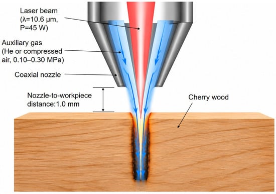
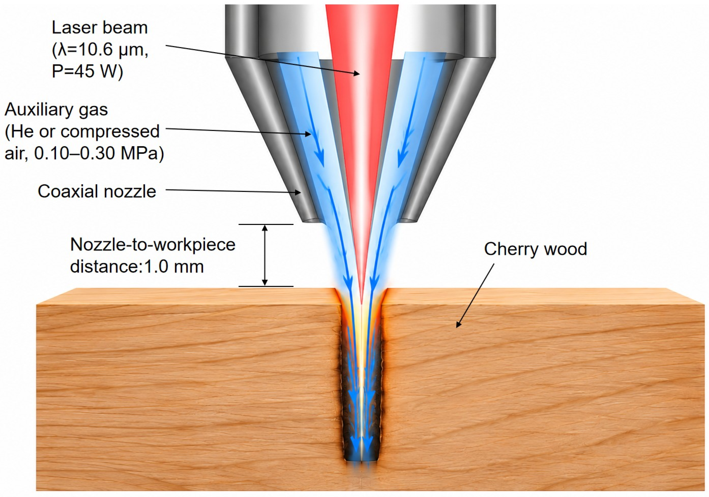
A schematic illustration of the gas-assisted laser cutting process is shown in Figure 1, illustrating the coaxial delivery of the laser beam and auxiliary gas through the nozzle and the subsequent gas flow into the wood kerf.
Figure 1.
Schematic illustration of the gas-assisted laser cutting process of cherry wood. The red region represents the laser beam, while the blue arrows indicate the auxiliary gas flow direction.
Considering the geometric symmetry of the coaxial nozzle-kerf configuration and the approximately symmetric distribution of the auxiliary gas jet about the central plane, a symmetric computational domain was adopted to reduce computational cost. The gas flow was assumed to be symmetric about the central plane of the model. Therefore, one-half of the physical domain was constructed and solved. This simplification preserves the principal flow characteristics in the nozzle outlet, kerf entrance, and internal kerf regions while reducing computational requirements.
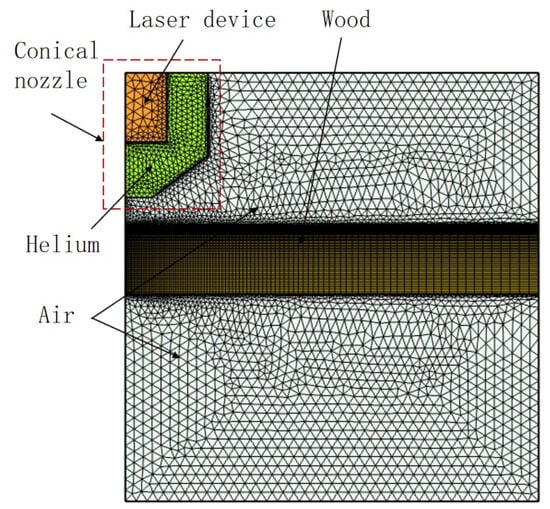
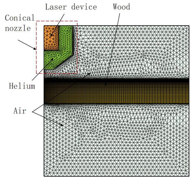
The computational domain was discretized using free triangular elements. Relatively coarser elements were used in non-critical regions, including the surrounding air domain, whereas local mesh refinement was applied to the nozzle outlet, kerf entrance, and internal kerf regions, where relatively high velocity and pressure gradients occurred. This mesh strategy provided a balance between numerical accuracy and computational efficiency. The finite element model and mesh configuration of gas-assisted laser cutting of wood are shown in Figure 2.
Figure 2.
Finite element model and mesh configuration of gas-assisted laser cutting of wood. The red dashed box highlights the nozzle region, while the different colors distinguish the computational domains.
2.5. Experimental Research Methodology
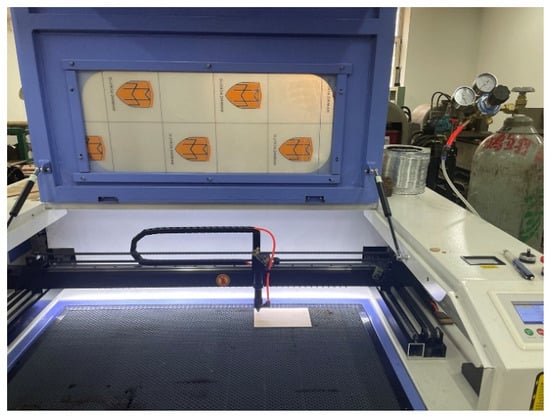
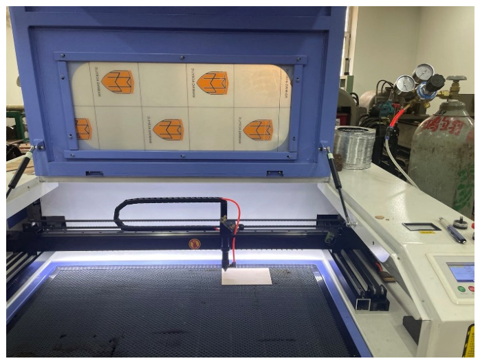
Experimental investigations were conducted using a CO2 laser cutting system (Jinan Baome Numerical Control Technology Co., Ltd., Jinan, China), as shown in Figure 3. The laser wavelength was 10.6 µm, the rated power was 80 W, the maximum processing speed was 200 mm/s, the spot diameter was 0.1 mm, the pulse width was 20 ns, and the pulse repetition frequency ranged from 1 kHz to 10 kHz. The focal length of the focusing lens was 63.5 mm. The laser focal position was fixed at 0.5 mm below the upper surface of the cherry wood specimen and remained unchanged throughout all experiments. Cherry wood was selected as the experimental material because of its relatively uniform texture and stable machining characteristics. The specimen dimensions were 120 mm × 80 mm × 10 mm (length × width × thickness), and the moisture content was maintained at approximately 11%. Industrial-grade helium with a purity higher than 99.999% and compressed air were used as the auxiliary gases.
Figure 3.
Experimental setup for gas-assisted laser cutting of cherry wood.
During the experiments, the workpiece was fixed on the workbench, and the laser beam was delivered to the processing region through the optical delivery system. The auxiliary gas pressure was regulated using a pressure-reducing valve and injected coaxially onto the wood surface through the nozzle. Kerf width, cutting depth, and surface roughness were selected as evaluation indicators of kerf formation quality. All experiments were conducted at room temperature of approximately 22 °C and relative humidity of 36%. The laser power and cutting speed were fixed at 45 W and 24 mm/s, respectively, to provide a stable reference condition without complete penetration of the specimens, thereby allowing cutting depth to be quantitatively evaluated. The nozzle-to-workpiece distance was maintained at 1.0 mm to reduce free-jet diffusion and provide stable coupling between the coaxial auxiliary gas jet and the kerf entrance. These parameters were held constant so that the effects of auxiliary gas type and inlet pressure could be evaluated independently of changes in laser energy input and nozzle position. The experimental conditions are summarized in Table 1.
Table 1.
Experimental conditions for cutting tests.
Kerf width and cutting depth were measured using a T004 digital microscope (Shenzhen Supereyes Technology Co., Ltd., Shenzhen, China) at 200× magnification. Cutting depth was defined as the vertical distance from the kerf entrance surface to the deepest point of the kerf. Surface roughness was measured using a TIME3200 handheld roughness meter (Beijing Time High Technology Co., Ltd., Beijing, China). Measurements were performed along the kerf wall direction. Representative kerf wall morphologies were examined using an Apreo S scanning electron microscopy (SEM) (Thermo Fisher Scientific Inc., Waltham, MA, USA). Before SEM observation, the specimens were gold-coated to improve surface conductivity. For each experimental condition, three independent specimens were prepared and evaluated using the same measurement procedure, and the results were expressed as mean ± standard deviation (SD). The experimental order was randomized to minimize systematic errors. The individual measurements of kerf width, cutting depth, and surface roughness for the three independent specimens under each experimental condition are presented in Table 2.
Table 2.
Individual experimental measurements under different auxiliary gas conditions.
The experimental analysis was conducted in two stages. First, air- and helium-assisted cutting were compared at an inlet pressure of 0.10 MPa, while laser power, cutting speed, and nozzle-to-workpiece distance were maintained at 45 W, 24 mm/s, and 1.0 mm, respectively. Independent-samples t-tests were used to evaluate differences in kerf width, cutting depth, and surface roughness between the two auxiliary gases. Second, under helium assistance, the effect of inlet pressure (0.10, 0.15, 0.20, and 0.30 MPa) on the three cutting responses was evaluated using one-way analysis of variance (ANOVA). Levene’s test was used to assess the homogeneity of variance, and 95% confidence intervals (CIs) were calculated where appropriate. Statistical significance was defined as p < 0.05. This sequential design was intended to distinguish the effect of gas type from the subsequent pressure effect rather than to constitute a full factorial gas-type × pressure experiment.
3. Results
3.1. Influence of Auxiliary Gas Type on Flow Field Characteristics
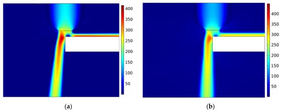
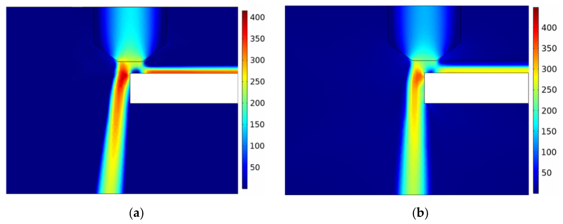
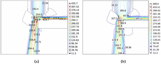
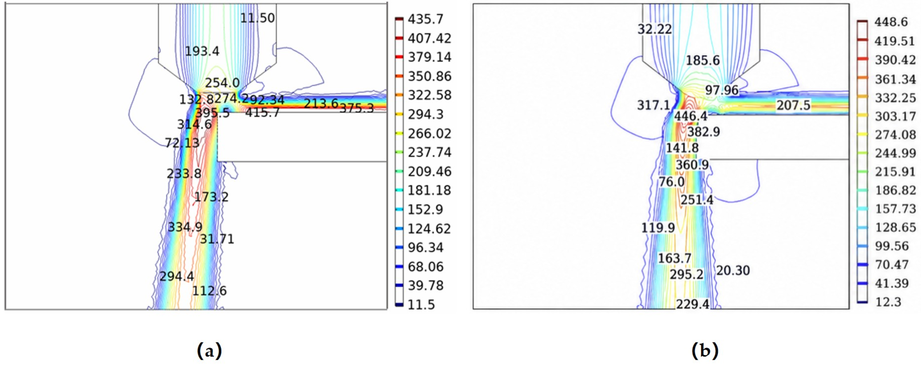
Figure 4 and Figure 5 present the velocity distributions under different auxiliary gas conditions at an inlet pressure of 0.10 MPa and a nozzle-to-workpiece distance of 1.0 mm. After exiting the nozzle, part of the auxiliary gas spread along the workpiece surface and dissipated into the surrounding atmosphere, whereas another portion entered the narrow kerf and propagated downward. Under air-assisted conditions, the gas jet exhibited relatively greater dispersion and deflection near the upper kerf region. In contrast, helium-assisted cutting showed a more concentrated high-velocity region along the kerf wall and cutting interface.
Figure 4.
Velocity distributions under different auxiliary gas conditions. (a) Air-assisted laser cutting; (b) helium-assisted laser cutting.
Figure 5.
Velocity distribution contours under different auxiliary gas conditions. (a) Air-assisted laser cutting; (b) helium-assisted laser cutting.
Figure 5 further compares the velocity distributions under different auxiliary gas conditions. The maximum velocities of the air and helium jets were 435.7 m/s and 448.6 m/s, respectively. Compared with air assistance, helium-assisted cutting exhibited a slightly higher velocity within the kerf. As the jets propagated along the kerf depth, the velocity difference between the two gases gradually increased. In the lower region of the kerf, helium jet maintained a velocity of approximately 250 m/s, whereas the air jet decreased to approximately 180 m/s. These results indicate that helium exhibited lower velocity attenuation during propagation within the kerf.
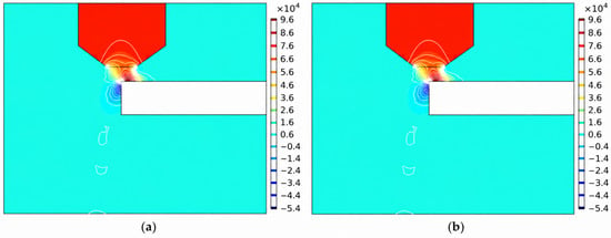
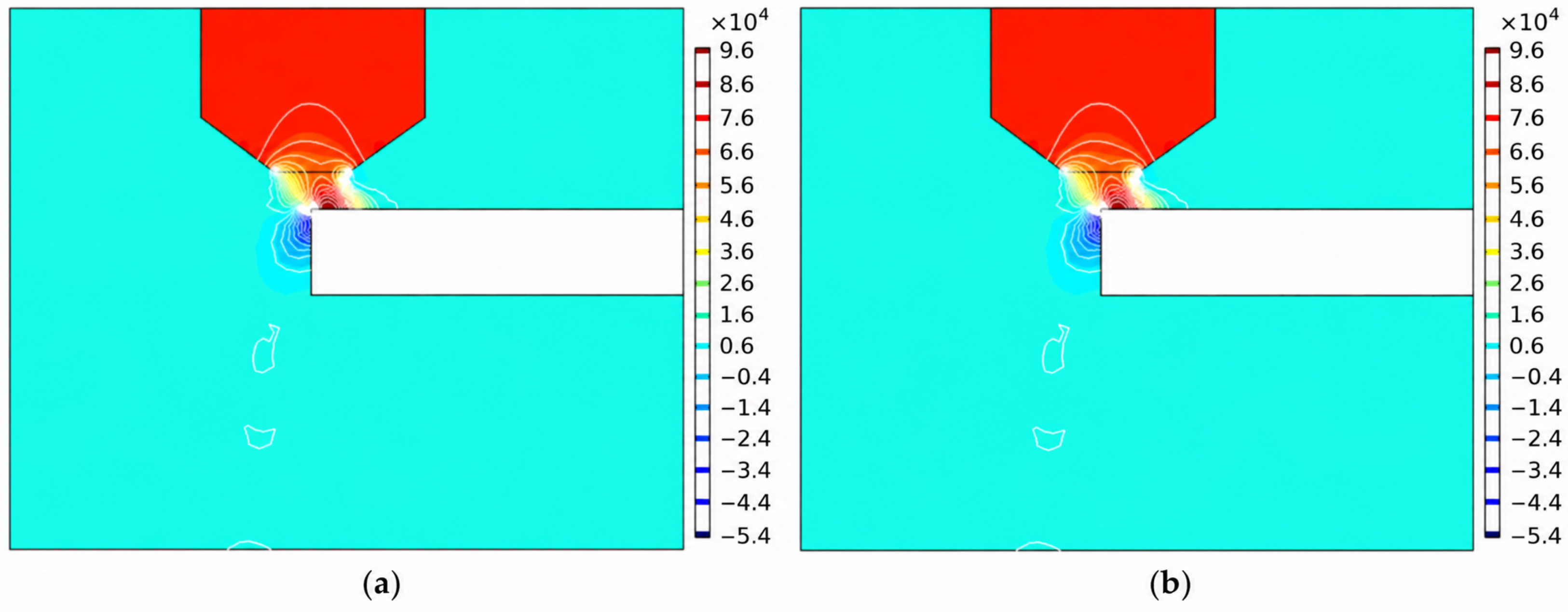
Figure 6 presents the pressure distributions under different auxiliary gas conditions. The pressure inside the nozzle remained relatively stable for both auxiliary gases. After exiting the nozzle, the gas jets expanded in the free-jet region between the nozzle outlet and the kerf entrance, resulting in rapid pressure variation. As the jets entered the narrow kerf, the expansion was restricted by the surrounding walls, and the pressure gradually decreased along the kerf depth before approaching a relatively stable distribution. The minimum pressures along the nozzle axis were approximately −0.054 MPa for air-assisted cutting and −0.064 MPa for helium-assisted cutting. Compared with air assistance, helium assistance exhibited a slightly lower-pressure region, particularly in the upper and middle regions of the kerf.
Figure 6.
Pressure distribution contours under different auxiliary gas conditions. (a) Air-assisted laser cutting; (b) helium-assisted laser cutting.
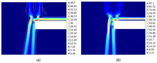
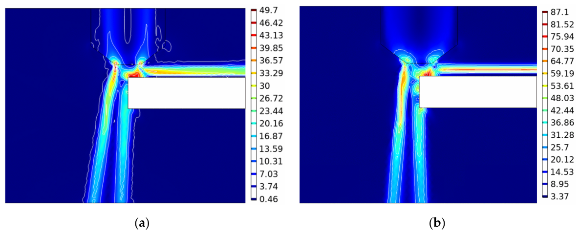
Figure 7 illustrates the wall shear stress distributions under different auxiliary gas conditions. The two gases showed similar overall distribution patterns, with relatively high wall shear stress values concentrated mainly near the upper region of the kerf and gradually decreasing along the depth direction. Compared with air-assisted cutting, helium-assisted cutting exhibited a more continuous high-shear-stress region along the kerf wall.
Figure 7.
Wall shear stress distributions under different auxiliary gas conditions. (a) Air-assisted laser cutting; (b) helium-assisted laser cutting.
Overall, auxiliary gas type influenced the flow field characteristics within the kerf. Compared with air assistance, helium-assisted cutting exhibited higher velocity retention, stronger pressure variation, and a more continuous wall shear stress distribution under the investigated conditions. Based on these simulated flow characteristics, helium was selected as the auxiliary gas for subsequent simulations involving inlet pressure and nozzle-to-workpiece distance.
3.2. Influence of Inlet Pressure on Flow Field Characteristics
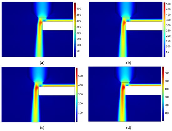
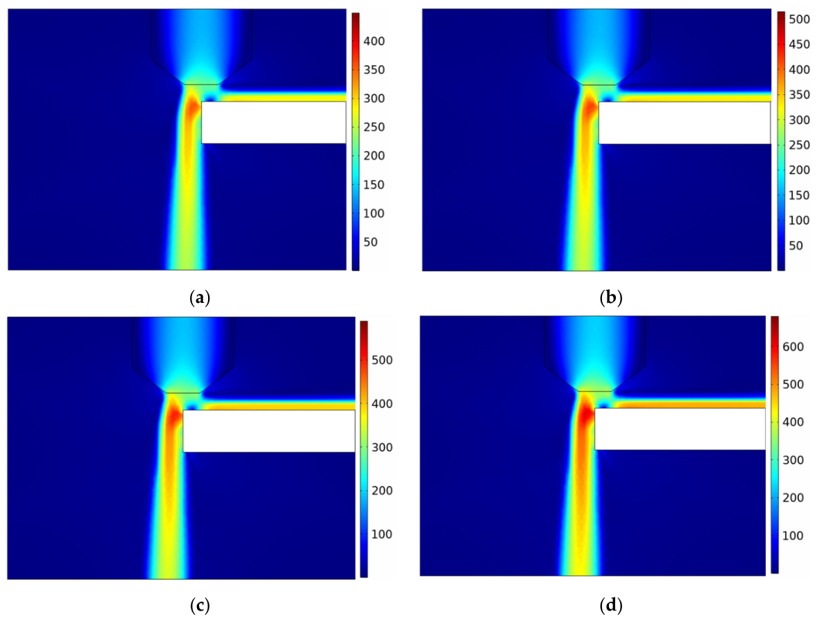
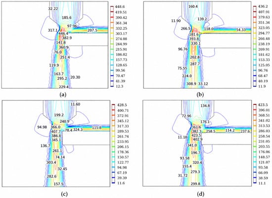
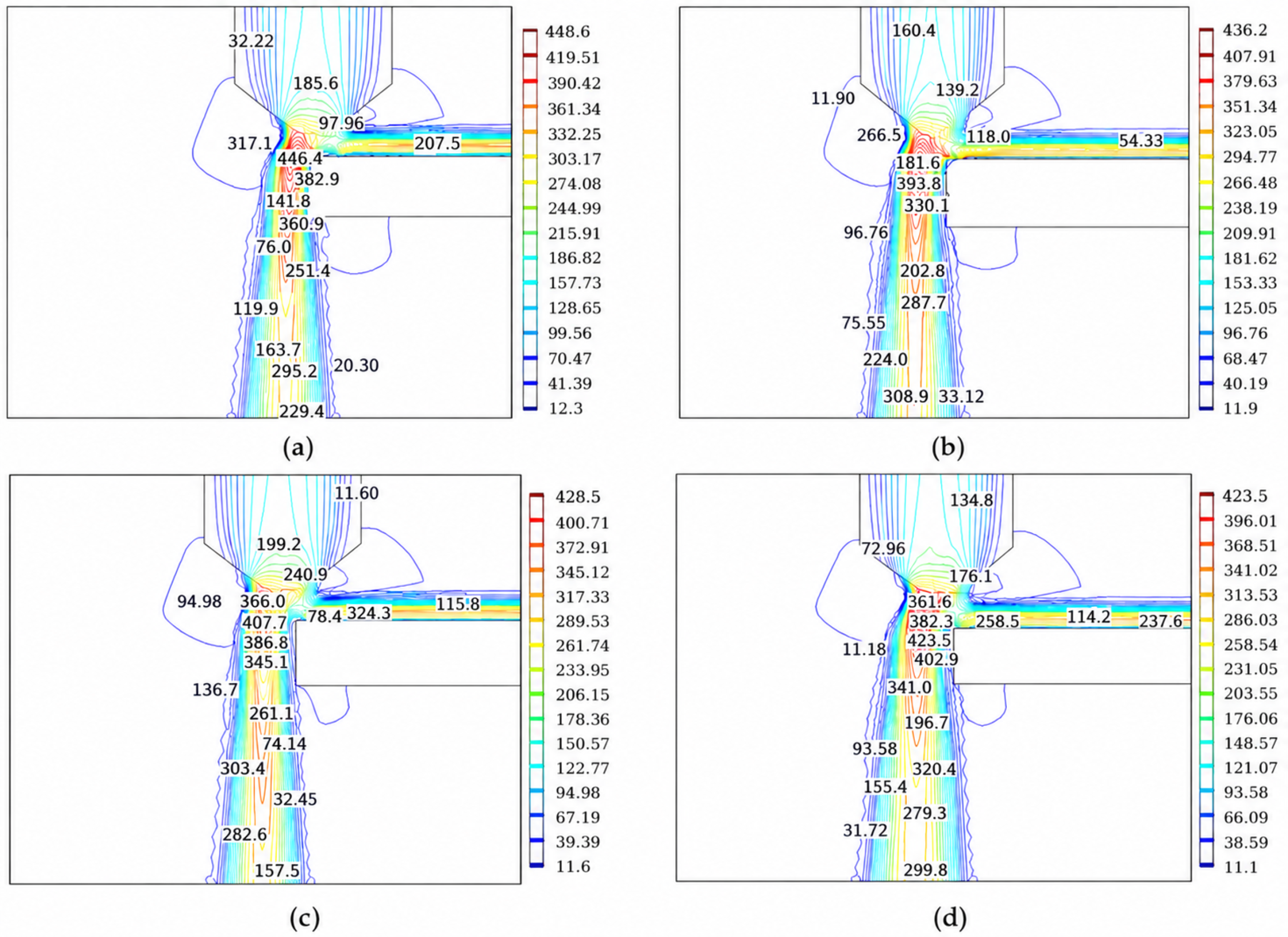
Figure 8 presents the velocity distributions under different inlet pressures during helium-assisted laser cutting. The inlet pressures were set to 0.10 MPa, 0.15 MPa, 0.20 MPa, and 0.30 MPa. As the inlet pressure increased, the jet velocity within the kerf increased continuously. When the inlet pressure increased from 0.10 to 0.30 MPa, the maximum velocity increased from 448.6 to 684.9 m/s. Meanwhile, the high-velocity region extended further toward the lower part of the kerf. At higher inlet pressure, more pronounced velocity gradients appeared near the kerf outlet and lateral regions.
Figure 8.
Velocity distributions under different inlet pressures. (a) 0.10 MPa; (b) 0.15 MPa; (c) 0.20 MPa; (d) 0.30 MPa.
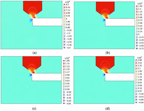
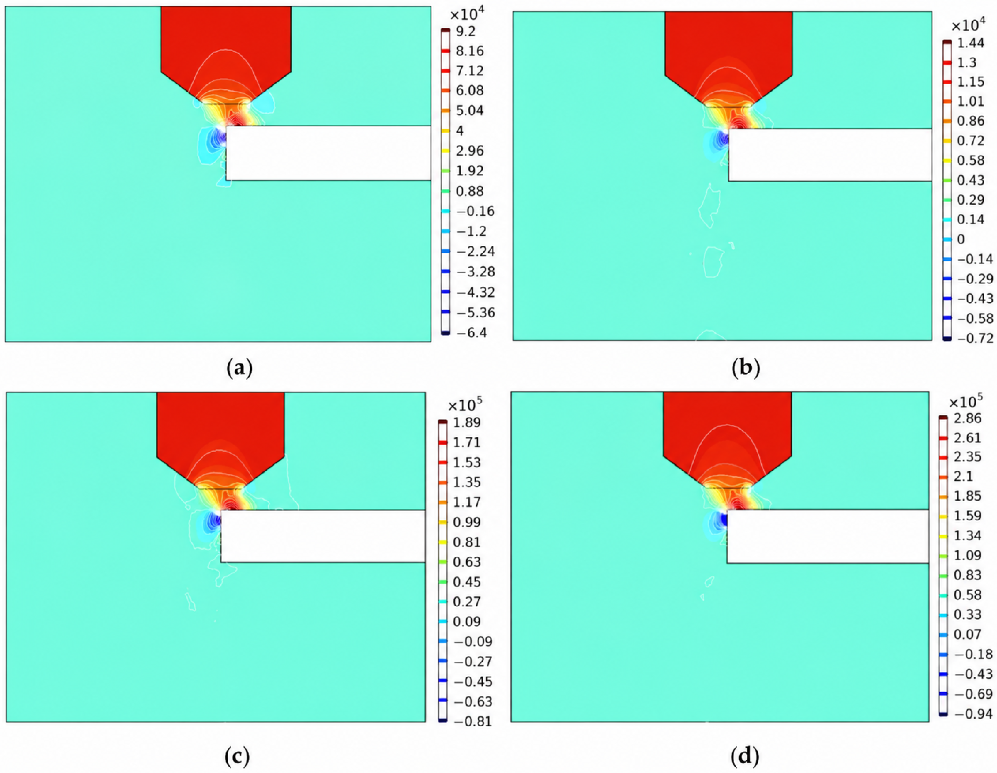
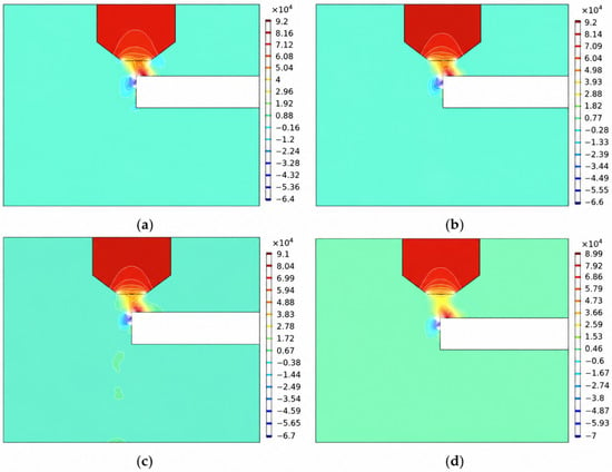
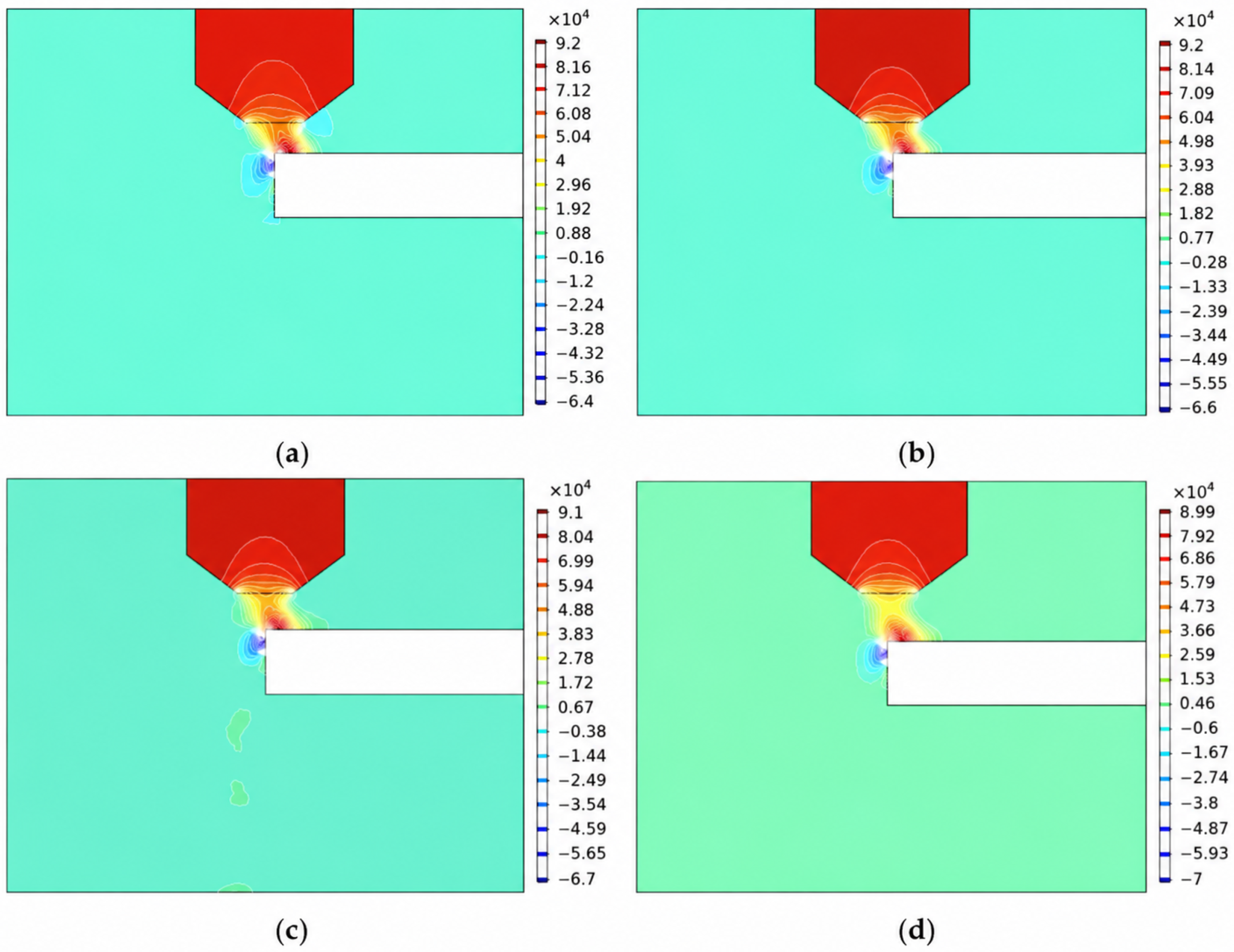
Figure 9 presents the pressure distributions under different inlet pressures. Increasing the inlet pressure enhanced the pressure gradient between the nozzle outlet and the kerf entrance. When the inlet pressure increased from 0.10 to 0.30 MPa, the minimum pressure decreased from approximately −0.064 to −0.094 MPa. The pressure distributions along the kerf depth showed similar variation patterns under different pressure conditions. Because of wall confinement and boundary layer development, the pressure decreased rapidly near the entrance region and gradually approached atmospheric pressure toward the outlet region.
Figure 9.
Pressure distribution contours under different inlet pressures. (a) 0.10 MPa; (b) 0.15 MPa; (c) 0.20 MPa; (d) 0.30 MPa.
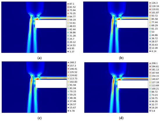
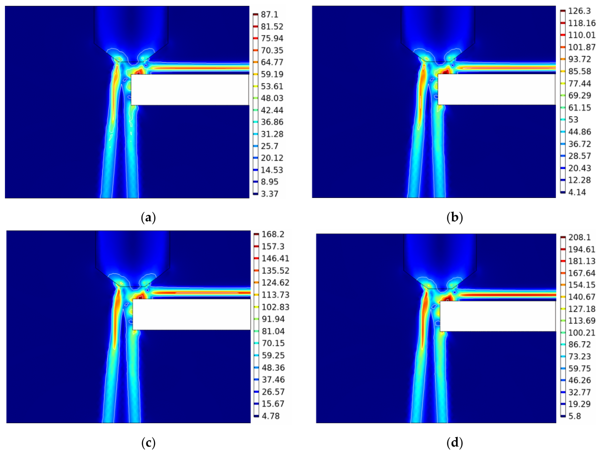
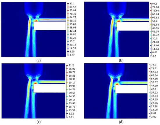
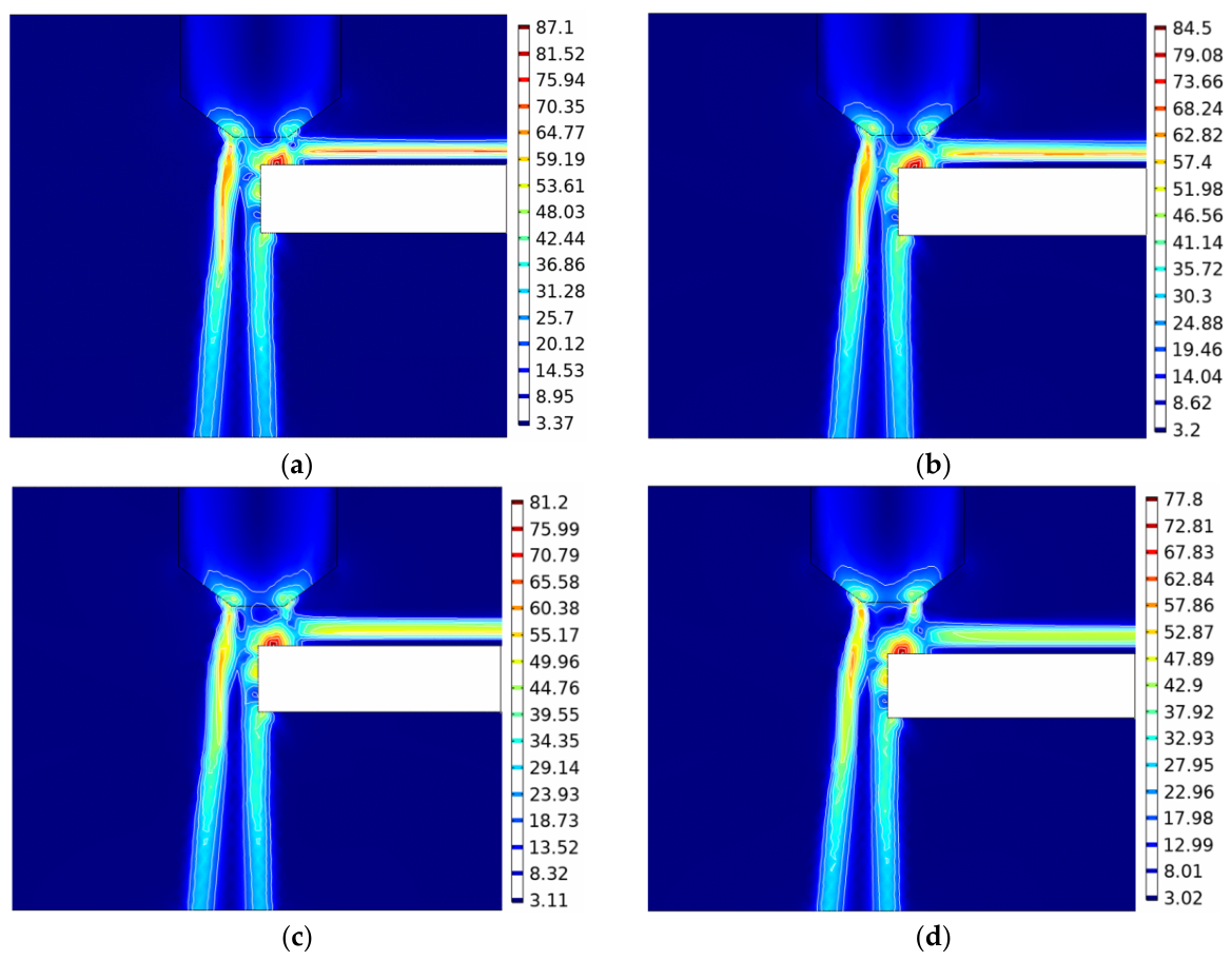
Figure 10 illustrates the wall shear stress distributions under different inlet pressures. The overall distribution patterns were similar among the different pressure conditions, with high-value regions mainly concentrated near the cutting surface and upper kerf region. As the inlet pressure increased, the wall shear stress gradually increased, accompanied by an expansion of the high-value region near the kerf entrance. However, the variation in wall shear stress became comparatively smaller in the deeper region of the kerf due to flow momentum dissipation and wall friction.
Figure 10.
Wall shear stress distributions under different inlet pressures. (a) 0.10 MPa; (b) 0.15 MPa; (c) 0.20 MPa; (d) 0.30 MPa.
3.3. Influence of Nozzle-to-Workpiece Distance on Flow Field Characteristics
Figure 11 illustrates the velocity distributions under different nozzle-to-workpiece distances at an inlet pressure of 0.10 MPa. The nozzle-to-workpiece distances were set to 1.0 mm, 1.2 mm, 1.5 mm, and 2.0 mm. Increasing the nozzle-to-workpiece distance enlarged the free-jet region between the nozzle outlet and the workpiece surface and was accompanied by greater jet diffusion before the gas entered the kerf. When the nozzle-to-workpiece distance increased from 1.0 to 2.0 mm, the maximum jet velocity decreased from 448.6 to 423.5 m/s. After entering the confined kerf, the velocity distribution showed relatively limited variation among the different nozzle positions.
Figure 11.
Velocity distribution contours under different nozzle-to-workpiece distances. (a) 1.0 mm; (b) 1.2 mm; (c) 1.5 mm; (d) 2.0 mm.
Figure 12 presents the pressure distributions under different nozzle-to-workpiece distances. As the nozzle-to-workpiece distance increased, the low-pressure region near the nozzle outlet and the kerf entrance gradually expanded. However, the pressure distribution inside the kerf remained relatively stable, especially in the deeper region. These results indicate that nozzle-to-workpiece distance mainly affected the free-jet and kerf entrance regions, whereas its effect on the deeper internal pressure field was limited.
Figure 12.
Pressure distribution contours under different nozzle-to-workpiece distances. (a) 1.0 mm; (b) 1.2 mm; (c) 1.5 mm; (d) 2.0 mm.
Figure 13 illustrates the wall shear stress distributions under different nozzle-to-workpiece distances. The wall shear stress exhibited similar distributions among different nozzle positions, with high-value regions mainly located near the kerf entrance and upper kerf wall. As the nozzle-to-workpiece distance increased, the wall shear stress near the upper kerf region decreased slightly, whereas the deeper region of the kerf exhibited relatively limited variation.
Figure 13.
Wall shear stress distributions under different nozzle-to-workpiece distances. (a) 1.0 mm; (b) 1.2 mm; (c) 1.5 mm; (d) 2.0 mm.
3.4. Experimental Analysis
The experimental results were analyzed to determine whether the simulated effects of auxiliary gas type and inlet pressure were reflected in the experimentally measured cutting responses. The comparison between air- and helium-assisted cutting at 0.10 MPa and the pressure-dependent experiments under helium assistance are presented below.
Table 3 presents the independent-samples t-test results for air- and helium-assisted cutting at 0.10 MPa. Helium-assisted cutting produced a significantly smaller kerf width than air-assisted cutting, decreasing from 0.391 ± 0.014 mm to 0.352 ± 0.012 mm (t = 3.801, p = 0.019). Surface roughness decreased significantly from 3.479 ± 0.090 μm under air assistance to 2.943 ± 0.123 μm under helium assistance (t = 6.088, p = 0.004). The corresponding 95% CIs for the air-minus-helium mean differences were 0.011~0.069 mm for kerf width and 0.292~0.781 μm for surface roughness, respectively. In contrast, cutting depth increased slightly from 3.046 ± 0.094 mm to 3.158 ± 0.087 mm, but the difference was not statistically significant (t = −1.519, p = 0.203; 95% CI was −0.317~0.093 mm). Under the investigated conditions, auxiliary gas type produced statistically significant differences in kerf width and surface roughness, whereas cutting depth was comparatively insensitive to the gas change.
Table 3.
Independent samples t-test results for air versus helium at 0.10 MPa.
Table 4 presents one-way ANOVA results for the effect of helium inlet pressure on cutting responses. Under helium assistance, inlet pressure had a statistically significant effect on kerf width (F(3, 8) = 4.402, p = 0.042) and surface roughness (F(3, 8) = 11.897, p = 0.003). In contrast, the inlet pressure effect on cutting depth was not statistically significant (F(3, 8) = 2.355, p = 0.148). Thus, within the investigated pressure range, helium inlet pressure significantly affected kerf width and surface roughness, whereas no statistically significant effect on cutting depth was detected.
Table 4.
One-way ANOVA results for the effect of helium inlet pressure on cutting responses.
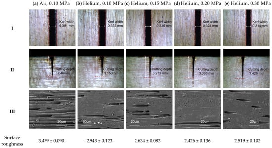
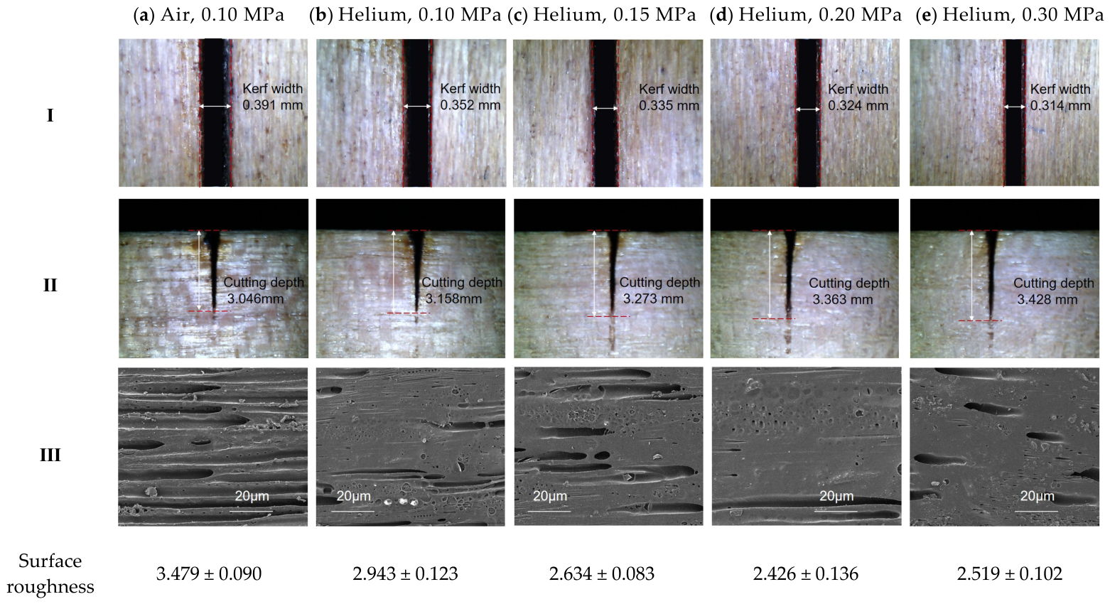
To further illustrate the experimental responses, representative kerf morphologies under different gas-assisted cutting conditions are presented in Figure 14. All specimens were processed at a fixed laser power of 45 W, cutting speed of 24 mm/s, and nozzle-to-workpiece distance of 1.0 mm, while the auxiliary gas type or helium inlet pressure varied according to the experimental design.
Figure 14.
Representative kerf morphologies of cherry wood under different gas-assisted cutting conditions. (I) Kerf width measured from top-view optical microscopy images; (II) Cutting depth measured from cross-sectional optical microscopy images; (III) Kerf wall surface morphology observed by SEM (images taken from the middle region of kerf wall).
At the same inlet pressure of 0.10 MPa, the air- and helium-assisted specimens exhibited distinguishable kerf characteristics. The helium-assisted condition showed a narrower kerf and a comparatively more uniform kerf wall morphology, consistent with the significantly lower kerf width and surface roughness identified by the independent- samples t-tests. In contrast, the cross-sectional images showed relatively limited differences in cutting depth between the two gases, consistent with the non-significant statistical result.
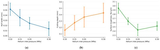
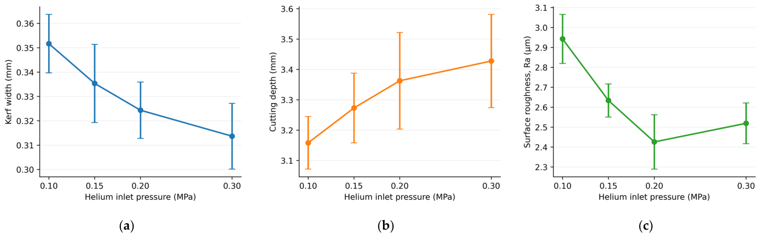
Under helium assistance, kerf width gradually decreased from 0.352 to 0.314 mm as the inlet pressure increased from 0.10 to 0.30 MPa, whereas cutting depth increased from 3.158 to 3.428 mm without a statistically significant overall pressure effect. Surface roughness decreased from 2.943 μm at 0.10 MPa to 2.426 μm at 0.20 MPa and then slightly increased to 2.519 μm at 0.30 MPa. These morphological trends were generally consistent with the measured cutting responses and corresponding statistical results, which showed significant pressure effects on kerf width and surface roughness but no significant effect on cutting depth.
Table 5 summarizes the quantitative comparison between the simulated flow characteristics and experimental cutting responses. At 0.10 MPa, helium increased the simulated maximum jet velocity by 2.96% compared with air, while kerf width and surface roughness decreased by 9.97% and 15.41%, respectively. Increasing helium inlet pressure from 0.10 to 0.30 MPa increased the simulated maximum velocity by 52.68%, accompanied by reductions of 10.80% in kerf width and 14.41% in surface roughness. These results indicate corresponding changes in simulated flow behavior and experimental cutting responses rather than direct quantitative validation of the CFD model.
Table 5.
Quantitative comparison of numerical flow characteristics and experimental cutting responses under different auxiliary gas conditions.
4. Discussion
The present study examined the effects of auxiliary gas from the perspective of the internal kerf flow field and experimentally measured cutting responses. Previous studies have mainly evaluated the effects of auxiliary gas using macroscopic indicators, such as kerf morphology, carbonization degree, and surface quality [7,17,18,19]. However, the aerodynamic behavior within the narrow kerf remains insufficiently understood. In this study, the effects of auxiliary gas were analyzed in terms of velocity distribution, pressure variation, and wall shear stress, providing further insight into the internal flow environment associated with gas-assisted laser cutting of wood.
The simulation results showed that helium-assisted cutting exhibited higher velocity retention, stronger pressure variation, and a more continuous high-shear region along the kerf wall than air-assisted cutting under the investigated conditions. Helium also exhibited a more concentrated jet propagation pattern within the narrow kerf. These differences were associated with the distinct physical properties of the two gases and suggest a more favorable flow environment for the transport of laser-generated products. Furthermore, the inert nature of helium may limit oxygen-related reactions and associated thermal damage during laser processing [18,19]. In addition to these aerodynamic and oxidation-related effects, laser-induced wood pyrolysis releases gaseous products that may influence the local kerf flow. Within the narrow kerf, these gases may generate local counter-pressure against the auxiliary gas jet, potentially modifying velocity, pressure gradients, and wall shear stress near the heated interface. However, because thermal decomposition and oxidation reactions were not explicitly modeled, these effects were not quantitatively evaluated in the present study.
The pressure and wall shear stress distributions provide further insight into the interaction between auxiliary gas flow and kerf region. During gas-assisted laser cutting, the pressure gradient generated by the jet and the shear stress acting along the kerf wall influence momentum transfer between the gas flow and the kerf surface. Previous studies of metallic laser cutting have shown that auxiliary gas pressure and jet characteristics affect material removal and cutting stability [10,15,25]. However, wood differs from metallic materials because laser irradiation involves thermal decomposition, carbonization, and volatile release rather than the formation of a conventional molten layer. Therefore, variations in velocity, pressure, and wall shear stress may affect the local flow environment within the kerf and potentially influence the transport conditions of laser-generated products. The present study extends the understanding of gas-assisted laser cutting of wood by showing that velocity retention, pressure variation and wall shear stress are important characteristics for evaluating the internal kerf flow environment.
The effect of inlet pressure further demonstrated the influence of jet intensity on the internal flow field. Increasing inlet pressure enhanced jet velocity and wall shear stress, particularly near the kerf entrance. However, the more pronounced velocity gradients at higher pressures may promote local flow disturbances and nonuniform transport of decomposition products, potentially contributing to the slight increase in surface roughness at 0.30 MPa. Similar trends have been reported in studies of metallic and composite laser cutting, where excessive auxiliary gas pressure may produce less uniform flow structures and affect processing stability [8,15,16]. Although shock-related effects may occur in compressible high-speed jets, their presence cannot be established from velocity magnitude alone and requires evaluation of the local Mach number and flow-field discontinuities. Since shock formation and kerf wall instability were not verified in the present model, these mechanisms remain possible explanations rather than confirmed causes of the observed roughness variation.
The influence of nozzle-to-workpiece distance was comparatively limited relative to auxiliary gas type and inlet pressure. Increasing the nozzle distance enlarged the free-jet development region between the nozzle outlet and workpiece surface, resulting in greater jet diffusion and velocity loss before the gas entered the kerf. However, once the gas entered the confined kerf, the downstream velocity, pressure, and wall shear stress distributions showed relatively limited variation because of the confinement imposed by the kerf walls. This result indicates that nozzle-to-workpiece distance mainly affects the interaction between the free jet and kerf entrance, whereas its influence on the deeper internal flow field is comparatively limited.
The experimental results showed response patterns consistent with the numerical analysis. At 0.10 MPa, helium-assisted cutting produced significantly smaller kerf width and lower surface roughness than air-assisted cutting, whereas the difference in cutting depth was not statistically significant. These experimental trends correspond to the simulated differences in jet propagation and wall shear stress between helium and air, suggesting that changes in auxiliary gas flow characteristics are more readily reflected in kerf geometry and surface condition than in penetration depth under the investigated condition.
The pressure-dependent experiments showed a similar response. Increasing helium inlet pressure significantly affected kerf width and surface roughness, whereas cutting depth showed no significant response. The numerical results showed that increasing inlet pressure increased jet velocity and wall shear stress, particularly near the kerf entrance and upper kerf region. Taken together, the numerical and experimental results suggest that auxiliary gas pressure primarily modifies the flow environment associated with the kerf wall and entrance region, while cutting depth remains comparatively insensitive to pressure variation within the investigated range. This observation also indicates that increasing auxiliary gas pressure does not necessarily result in a proportional improvement in all cutting responses. The pressure-dependent experimental results are summarized in Figure 15, which illustrates the variations in kerf width, cutting depth, and surface roughness under different helium inlet pressures.
Figure 15.
Effects of helium inlet pressure during laser cutting of cherry wood. (a) Kerf width; (b) cutting depth; (c) surface roughness.
The quantitative comparison in Table 5 further supports the correspondence between the simulated flow characteristics and experimental cutting responses. However, the RNG k-ε model predicts gas velocity, pressure, and wall shear stress within a prescribed kerf geometry rather than directly predicting kerf width or cutting depth. Therefore, relative errors between these different physical quantities cannot be meaningfully calculated. Although the observed trends provide indirect experimental support for the numerical interpretation, direct validation of the CFD model requires measurements of corresponding flow-field variables, such as jet velocity or pressure, under matched boundary conditions.
From a practical perspective, the combined numerical and experimental approach provides a basis for selecting auxiliary gas conditions in precision wood laser cutting. The observed reductions in kerf width and surface roughness under helium assistance indicate its potential for applications requiring improved dimensional accuracy and surface quality, such as precision cutting of wood components and furniture manufacturing. Furthermore, the effects of inlet pressure and nozzle-to-workpiece distance on the internal flow field provide useful guidance for process parameter selection. However, the relatively high cost of industrial-grade helium may limit its economic feasibility for large-scale wood processing. Its practical application requires balancing improvements in cutting quality against additional gas consumption costs. Helium assistance may therefore be more suitable for high-precision applications where improved dimensional accuracy and surface quality justify the increased operating cost. Further evaluation of gas consumption and comparison with lower-cost alternatives, such as nitrogen, are needed to assess its industrial viability.
The combined numerical simulation and experimental analysis provide further insight into the role of auxiliary gas regulation in wood laser cutting; however, several limitations require further investigation. First, the wood substrate was simplified as a homogeneous and isotropic material in the simulation, whereas actual wood exhibits direction-dependent thermal properties, permeability, and anisotropic structures. These factors may affect kerf formation and consequently alter local gas dispersion and wall shear stress distributions [11,18]. Future studies will incorporate an orthotropic material model to better represent the interaction between wood anisotropy, thermal degradation, and auxiliary gas flow.
Second, the present simulation mainly focused on steady-state gas flow characteristics, while transient flow evolution, dynamic material transport, pyrolysis gas generation, and gas-phase reactions were not explicitly modeled. Further studies could develop transient thermo-fluid models incorporating laser energy absorption, thermal decomposition, and gas-phase interactions to clarify the interaction between laser processing and auxiliary gas flow.
Third, the present experimental evaluation focused on kerf width, cutting depth, and kerf-wall surface roughness, whereas the heat-affected zone was not independently quantified. Because the HAZ provides important information on thermal damage during wood laser processing, future studies should incorporate quantitative HAZ measurements together with temperature-field characterization to further evaluate the thermal effects of auxiliary gas regulation. Furthermore, because laser power and cutting speed were held constant, the present study did not involve systematic multi-parameter optimization. Future work will investigate the combined effects of laser parameters and auxiliary gas conditions to establish optimized processing conditions for wood laser cutting.
5. Conclusions
This study investigated the internal gas flow characteristics and their correspondence with experimentally measured kerf responses during gas-assisted laser cutting of cherry wood. The main conclusions are as follows:
- (1)
- Auxiliary gas type significantly influenced the internal kerf flow characteristics. Compared with air-assisted cutting, helium-assisted cutting exhibited higher velocity retention, stronger pressure variation, and a more continuous wall shear stress distribution. At 0.10 MPa, the maximum jet velocities of air and helium were 435.7 and 448.6 m/s, respectively.
- (2)
- Increasing helium inlet pressure from 0.10 to 0.30 MPa increased the maximum jet velocity from 448.6 to 684.9 m/s and enhanced wall shear stress. In contrast, increasing nozzle-to-workpiece distance mainly affected the free-jet and kerf entrance regions, with limited influence on the deeper internal flow field.
- (3)
- Experimental results showed that helium assistance significantly reduced kerf width and surface roughness compared with air assistance at 0.10 MPa, whereas no statistically significant difference in cutting depth was detected. Under helium assistance, increasing inlet pressure from 0.10 to 0.30 MPa reduced kerf width from 0.352 to 0.314 mm, while surface roughness reached a minimum of 2.426 μm at 0.20 MPa. Inlet pressure significantly affected kerf width (p = 0.042) and surface roughness (p = 0.003), whereas no statistically significant effect on cutting depth was detected (p = 0.148).
- (4)
- The numerical and experimental results showed qualitatively consistent response patterns, providing further insight into auxiliary gas flow behavior and its relationship with kerf formation during wood laser cutting.
Author Contributions
Conceptualization, Q.L. and C.Y.; methodology, J.H.; software, Q.L.; validation, F.W.; investigation, C.Y.; data curation, F.W.; writing—original draft preparation, Q.L. and J.H.; writing—review and editing, F.W. All authors have read and agreed to the published version of the manuscript.
Funding
This research was funded by Research Start-up Fund Project of Oriented Training (Introduction of Talents) of Heilongjiang Bayi Agricultural University (XYB202205 and XDB202205) and Research Project on Ecological Environmental Protection in Heilongjiang Province (HST2025GF002).
Data Availability Statement
The original contributions presented in this study are included in the article. Further inquiries can be directed to the corresponding authors.
Conflicts of Interest
The authors declare no conflicts of interest.
Abbreviations
The following abbreviations are used in this manuscript:
| Abbreviation | Significance | Unit |
| ρh | gas density | kg/m3 |
| vx | velocity components in the x | m/s |
| vy | velocity components in the y | m/s |
| vz | velocity components in the z | m/s |
| PL | fluid pressure | Pa |
| τx | viscous stress components | N/m2 |
| τy | viscous stress components | N/m2 |
| τz | viscous stress components | N/m2 |
| Fx | body force components in the x-direction | N/m3 |
| Fy | body force components in the y-direction | N/m3 |
| Fz | body force components in the z-direction | N/m3 |
| Cp | specific heat capacity | J/(kg·K) |
| T | fluid temperature | K |
| δ | thermal conductivity coefficient | W/(m·k) |
| ST | heat source term | |
| ak | inverse effective Prandtl numbers for turbulent kinetic energy | |
| aε | inverse effective Prandtl numbers for turbulent dissipation rate | |
| μeff | effective viscosity | |
| Gk | turbulent kinetic energy generated by mean velocity gradients | m2/s2 |
| Gb | turbulent kinetic energy generated by buoyancy effects | m2/s2 |
| YM | expansion dissipation term | m2/s2 |
| Sk | customized source items | |
| Sε | customized source items |
References
- Lazov, L.; Narica, P.; Valiniks, J.; Pacejs, A. Optimization of CO2 laser parameters for wood cutting. Environ. Technol. Resour. Proc. Int. Sci. Pract. Conf. 2017, 3, 168–173. [Google Scholar] [CrossRef] [Scilit]
- Han, L.Y.; Wang, T.; Ma, F.H.; Shi, Y.M. Research on the application of laser cutting in non metallic material processing. Intern. Combust. Engine Parts 2025, 9, 61–63. [Google Scholar] [CrossRef]
- Wang, X. Analysis of the current application status and future development of laser processing technology. Sci. Technol. Innov. 2017, 22, 34–35. [Google Scholar]
- Bo, G. The current situation and application trend of laser processing technology and industry. MW Metal. Form. 2010, 10, 37–42+47. [Google Scholar]
- Wang, X.Y.; Ye, X. Analysis of auxiliary gas flow field for laser cutting of medium-thick plates. J. Shanghai Univ. Eng. Sci. 2025, 3, 300–306. [Google Scholar]
- Liang, P.P.; Wu, J.H.; Zhao, H.G.; Wang, Q.P.; Liu, M.L. Analysis of the cutting effect of laser processed birch. China For. Prod. Ind. 2023, 2, 30–34. [Google Scholar] [CrossRef]
- Peng, X.R.; Zhang, L.; Zhang, Z.K. Application and development of laser technology in wood processing: A review. J. Northwest For. Univ. 2021, 5, 202–206. [Google Scholar]
- Zhang, F.; Qian, L.Y.; Buck, D.; Bao, Y.H.; Guo, X.L. Influence of cryogenic CO2 on wood-plastic composite (WPC) turning-performance characteristics: A comparison with dry machining. Wood Mater. Sci. Eng. 2026, 21, 138–148. [Google Scholar] [CrossRef] [Scilit]
- Arshed, G.M.; Shuja, S.Z.; Yibas, B.S. Investigation into flow field in relation to laser gas assisted processing: Influence of assisting gas velocity on the flow field. Numer. Heat Transf. Part A Appl. 2014, 65, 556–583. [Google Scholar] [CrossRef] [Scilit]
- Sundar, M.; Nath, A.K.; Bandyopadhyay, D.K.; Chaudhuri, S.P.; Dey, P.K.; Misra, D. Effect of process parameters on the cutting quality in lasox cutting of mild steel. Int. J. Adv. Manuf. Technol. 2009, 40, 865–874. [Google Scholar] [CrossRef] [Scilit]
- Vicanek, M.; Simon, G. Momentum and heat transfer of an inert gas jet to the melt in laser cutting. J. Phys. D Appl. Phys. 1987, 20, 1191. [Google Scholar] [CrossRef] [Scilit]
- Nath, S.; Waugh, D.G.; Ormondroyd, G.A.; Spear, M.J.; Pitman, A.J.; Sahoo, S.; Curling, S.F.; Mason, P. CO2 laser interactions with wood tissues during single pulse laser-incision. Opt. Laser Technol. 2020, 126, 106069. [Google Scholar] [CrossRef] [Scilit]
- Guo, S.G. Analysis of High Pressure Assisted Gas Flow in Laser Cutting and Improvement of Nozzle Structure. Master’s Thesis, Shanghai Jiao Tong University, Shanghai, China, 2008. [Google Scholar]
- Ge, Y.Q.; Wang, W.X.; Cui, Z.Q.; Liu, X. Influence of assistant gas during Nd:YAG laser cutting of 5A06 aluminium alloy. Appl. Laser 2008, 5, 358–361. [Google Scholar]
- Zhang, Y.; Li, Q.; Tong, L.; Song, Y.Y.; Zhang, X.Y.; Sun, F. Simulation analysis of influence of laser cutting auxiliary gas parameters on cutting quality. Mech. Eng. Autom. 2020, 4, 44–46. [Google Scholar]
- Al-Sulaiman, F.; Yilbas, B.S.; Ahsan, M.; Karatas, C. CO2 laser cutting of Kevlar laminate: Influence of assisting gas pressure. Int. J. Adv. Manuf. Technol. 2009, 45, 62–70. [Google Scholar] [CrossRef] [Scilit]
- Yuan, R.; Yang, B.; Ruan, H.Y.; Wang, X. Flow field analysis of gas jets from nozzles for gas-assisted laser cutting. Key Eng. Mater. 2010, 419–420, 409–412. [Google Scholar] [CrossRef] [Scilit]
- Hernandez-Castaneda, J.C.; Sezer, H.K.; Li, L. Dual gas jet-assisted fibre laser blind cutting of dry pine wood by statistical modelling. Int. J. Adv. Manuf. Technol. 2010, 50, 195–206. [Google Scholar] [CrossRef] [Scilit]
- Orazi, L.; Darwish, M.; Reggiani, B. Investigation on the inert gas-assisted laser cutting performances and quality using supersonic nozzles. Metals 2019, 9, 1257. [Google Scholar] [CrossRef] [Scilit]
- Qin, T.; Zhong, Z.X.; Hui, J.; Zhou, L.; Huang, Y.X.; Long, Y.H. Experimental study on gas-assisted laser cutting carbon fiber reinforced plastic. Int. J. Adv. Manuf. Technol. 2022, 119, 6361–6370. [Google Scholar] [CrossRef] [Scilit]
- Adamík, L.; Kminiak, R.; Kyselica, K.; Igaz, R.; Kubovský, I. Optimisation of CO2 laser technological parameters and their impact on the surface quality of cut wood. Forests 2025, 16, 785. [Google Scholar] [CrossRef] [Scilit]
- Ružiak, I.; Igaz, R.; Kubovský, I.; Tudor, E.M.; Gajtanska, M.; Jankech, A. ANN prediction of laser power, cutting speed, and number of cut annual rings and their Influence on selected cutting characteristics of spruce wood for CO2 laser processing. Materials 2024, 17, 3333. [Google Scholar] [CrossRef] [Scilit] [PubMed]
- Zhang, L.X.; Li, Q. Influence of laser cutting parameters on auxiliary gas flow field. Mach. Electron. 2019, 2, 18–21. [Google Scholar]
- Kabardin, I.K.; Yavorsky, N.I.; Meledin, V.G.; Pravdina, M.K.; Gordienko, M.R.; Ezendeeva, D.P.; Kakaulin, S.V.; Usov, E.V.; A Kolotilov, V.; Krotov, S.V.; et al. Experimental investigation of applicability limits of K-ε turbulent model and Reynolds stresses transfer model in rotary-divergent flow under control via turning blades. J. Phys. Conf. Ser. 2020, 1677, 012014. [Google Scholar] [CrossRef] [Scilit]
- Zimmermann, C.; Lemcke, F.J.; Kabelac, S. Nusselt numbers from numerical investigations of turbulent flow in highly eccentric horizontal annuli. Int. Commun. Heat Mass Transf. 2019, 109, 104344. [Google Scholar] [CrossRef] [Scilit]
- Darwish, M.; Mrna, L.; Orazi, L.; Reggiani, B. Numerical modeling and Schlieren visualization of the gas-assisted laser cutting under various operating stagnation pressures. Int. J. Heat Mass Transf. 2020, 147, 118965. [Google Scholar] [CrossRef] [Scilit]
- Melhem, O.A.; Yilbas, B.S.; Shuja, S.Z.; Sahin, A.Z. Influence of assisting Gas type on the nusselt number and the skin friction on slots in relation to laser cutting. Heat Transf. Eng. 2013, 34, 852–862. [Google Scholar] [CrossRef] [Scilit]
- Riveiro, A.; Quintero, F.; Boutinguiza, M.; Val, J.S.; Comesaña, R.; Lusquiños, F.; Pou, J. Laser Cutting: A Review on the Influence of Assist Gas. Materials 2019, 12, 157. [Google Scholar] [CrossRef] [Scilit] [PubMed]

Disclaimer/Publisher’s Note: The statements, opinions and data contained in all publications are solely those of the individual author(s) and contributor(s) and not of MDPI and/or the editor(s). MDPI and/or the editor(s) disclaim responsibility for any injury to people or property resulting from any ideas, methods, instructions or products referred to in the content. |
© 2026 by the authors. Licensee MDPI, Basel, Switzerland. This article is an open access article distributed under the terms and conditions of the Creative Commons Attribution (CC BY) license.