


Abstract
In thermal power (TP) units equipped with hybrid energy storage (ES) systems, automatic generation control (AGC) command allocation and storage power control directly affect frequency regulation performance, assessment results, and operational sustainability. Existing strategies usually do not distinguish between AGC assessment periods and non-assessment periods. Therefore, ES devices may still charge or discharge when their output no longer contributes to the AGC assessment, resulting in unnecessary energy loss, reduced ramping capability, and poor state-of-charge (SOC) recovery. In addition, the available reserve capacity of TP units and the residual capacity of different storage devices are not fully utilized. To solve these problems, this paper proposes a joint frequency regulation control strategy for a thermal-hybrid ES system considering AGC time-sharing assessment characteristics and multimodal coordination. First, the AGC assessment process is analyzed according to the requirements of regulation rate, regulation time, and regulation accuracy. The response process of the thermal-hybrid ES system is divided into the initial response stage, acceleration stage, steady regulation stage, and assessment-ending stage. For upward and downward AGC command changes, an assessment-oriented optimal response trajectory is established. Based on the real-time output of the thermal unit, the overall frequency regulation reference command of the hybrid ES system is obtained. Second, a multimodal coordinated control strategy is developed. During the ramping stage, the operating mode is determined according to the SOC states of the battery and flywheel ES systems. The regulation command is allocated between the two devices according to their SOC margins, power characteristics, and charging or discharging constraints. Smooth correction factors are introduced to reduce excessive battery charging and discharging, while a nonlinear correction is used to prevent the flywheel from frequently operating outside its safe SOC range. During the non-assessment stage, a SOC recovery strategy is further designed by using the reserve capacity of the thermal unit and the remaining capacity of the storage devices. A case study is conducted using typical monthly AGC command data and actual response power data from a TP plant in Hubei Province. The rated capacities of the battery and flywheel are set to 2.0 MWh and 0.2 MWh, respectively. Compared with single-storage, full-compensation, proportional allocation, and partial multimodal control schemes, the proposed strategy achieves the best overall performance. The average regulation rate index, regulation time index, regulation accuracy index, comprehensive evaluation index, and AGC assessment success rate reach 1.99, 0.99, 0.99, 1.91, and 99%, respectively. The proposed strategy also obtains the highest net benefit of 12.023 million yuan.
1. Introduction
In the operational control of TP–ES frequency regulation systems, the allocation of automatic generation control (AGC) commands and the control of ES power output are two key factors affecting frequency regulation assessment performance and operational sustainability. Therefore, these two issues have become important research topics in this field.
For AGC command allocation, existing methods can generally be classified into three categories: proportional coefficient allocation strategies, deviation-based allocation strategies, and frequency-based allocation strategies. In proportional allocation strategies, Ref. [1] allocates AGC response commands according to the proportion of the available frequency regulation capacity of each regulation resource in the total system regulation capacity. However, this method is only suitable for frequency regulation tasks under small grid frequency deviations and usually leads to limited regulation performance [2]. Ref. [3] proposes a multi-objective optimization-based control strategy, in which frequency regulation performance, the state of charge of ES, and regulation cost are taken as objective functions to optimize the allocation coefficients of different regulation resources. Nevertheless, the superiority of the algorithm and the computing environment directly affect the response speed of ES, which makes the method less practical for large-scale second-level frequency regulation applications. Ref. [4] proposes a control method that dynamically adjusts the AGC proportional factor K by simultaneously considering the reserve capacity boundary of the TP unit and the SOC boundary of the hybrid ES system; however, only a single type of ES is considered.
The deviation-based allocation strategy refers to the use of the ES system to fully compensate for the deviation between the TP unit output and the AGC command. For example, Ref. [5] uses complete ensemble empirical mode decomposition with adaptive noise to obtain the deviation signals between the TP unit and the AGC command at different frequencies, and then allocates these deviation signals among different hybrid ES devices. Ref. [6] adopts variational mode decomposition to decompose the deviation signal between the TP unit output and the AGC command. Ref. [7] proposes a secondary frequency regulation control strategy for composite ES based on variable filtering time constants and fuzzy control. According to the rate of change in grid frequency, the internal frequency regulation command of the composite ES system is allocated by adaptively adjusting the filtering time constant and is further corrected using fuzzy control theory.
In frequency-based allocation strategies, filters are used to process the overall AGC command of the TP–ES system, thereby separating power signals in different frequency bands. Ref. [8] applies a discrete Fourier transform to the AGC power signal to obtain low-frequency and high-frequency components, where the low-frequency component is assigned to the TP unit and the high-frequency component is assigned to the ES system. Ref. [9] assigns the high-frequency component of the AGC command to the ES system by considering its fast response characteristics, achieving favorable frequency regulation performance. Ref. [10] uses a spatio-temporal filter based on empirical mode decomposition to decompose the frequency regulation demand into components with different frequencies, which are then allocated according to the output characteristics of the TP unit and ES system. Ref. [11] adopts ensemble empirical mode decomposition to process the AGC signal and reduce mode mixing caused by empirical mode decomposition. Ref. [12] constructs a power allocator at the TP–ES power allocation layer using improved complete ensemble empirical mode decomposition with adaptive noise and multi-scale permutation entropy, thereby realizing power allocation between the TP unit and the ES system. Ref. [13] decomposes the AGC command of a TP unit–flywheel ES system using a multi-layer variable-gain rate-limiting algorithm. Ref. [14] adopts an adaptive frequency regulation signal decomposition strategy for a TP unit–battery ES system. More recently, advanced optimization-based coordination has also been investigated for thermal power–hybrid ES frequency regulation. Ref. [15] developed a stochastic model predictive control strategy for a battery/flywheel HESS to improve the AGC performance of thermal generators, in which the HESS power is optimally distributed considering response uncertainty. Ref. [16] further proposed a two-layer control framework for thermal power units coupled with HESS, coordinating the power allocation between the thermal unit and HESS as well as the internal allocation between flywheel and electrochemical storage while considering SOC and battery-life constraints.
In terms of ES power control, some studies have controlled the output of ES based on its SOC state to prevent overcharging and overdischarging. For example, Ref. [17] develops an output strategy for ES to withdraw from the auxiliary frequency regulation system when its state of charge is unsuitable, in combination with ancillary service market rules. Ref. [18] optimizes the frequency regulation output of ES according to its SOC state based on fuzzy control theory. Ref. [19] proposes a comprehensive control method that adjusts the output power proportion according to system frequency and the SOC of the battery ES system, thereby optimizing the battery SOC and ensuring the sustainability of ES frequency regulation. Ref. [20] establishes a real-time optimization model for ES charging and discharging strategies, in which the compensation degree of ES for the real-time deviation between the AGC command and unit output is taken as the decision variable, and the maximization of frequency regulation performance and energy balance of the storage system is taken as the objective. For flywheel–battery HESSs, SOC-aware coordinated control has also received increasing attention. Ref. [21] developed a coordinated frequency-regulation strategy in which the battery and flywheel control coefficients are adjusted according to the frequency response and SOC states. Ref. [22] proposed a fuzzy-adaptive flywheel–battery HESS control strategy with SOC self-recovery, demonstrating that post-regulation SOC restoration can improve the subsequent regulation capability of the storage system. However, the above studies maintain frequency regulation sustainability at the expense of certain regulation performance.
Other studies have considered SOC recovery by using additional frequency regulation reserve resources to restore the SOC of ES, thereby ensuring both frequency regulation performance and regulation sustainability. Ref. [23] proposes a feedforward coordinated frequency regulation control strategy based on SOC prediction for ES batteries. When the TP–ES system receives an AGC command, the reserve power of the TP unit is used according to the predicted SOC values of individual storage units, thus realizing dynamic SOC recovery of each ES battery. This approach ensures the sustainability of ES frequency regulation while maintaining comprehensive regulation performance, including regulation time and response time. However, the above studies only consider a single battery ES system. As a result, the frequency regulation effect is limited by small capacity and short continuous charging and discharging duration, making it difficult to compensate for large power deficits in the system. Ref. [24] proposes five typical operating scenarios for a hybrid ES device and constructs corresponding composite ES charging and discharging strategies considering SOC states. However, SOC recovery is neglected, and frequency regulation sustainability is difficult to maintain under relatively small ES capacity planning. Ref. [25] designs frequency regulation command allocation coefficients for flywheel ES and battery ES systems based on fuzzy control logic, but the SOC recovery of the hybrid ES system is likewise ignored.
Based on the above analysis, existing studies on the operational control of TP–ES frequency regulation systems still face several limitations. Existing control strategies generally determine the ES output according to the instantaneous deviation between the AGC command and the thermal-unit output, without explicitly distinguishing the assessment-active period from the subsequent non-assessment period within a complete AGC command interval. After the regulation requirements for the current command have already been satisfied, continued ES charging or discharging no longer contributes to the corresponding AGC assessment indices, but still increases ES energy throughput, causes additional SOC excursions, and accelerates battery life degradation. Therefore, explicitly identifying the assessment boundary and coordinating ES operation differently during the assessment and non-assessment periods is necessary for simultaneously improving regulation performance and operational sustainability. To address the above limitations, this paper proposes a multimodal joint frequency regulation control strategy for a TP–hybrid ES system under AGC time-sharing assessment. The specific contributions are summarized as follows.
- (1)
- Assessment-oriented regulation-deviation control. Instead of requiring the ES system to continuously compensate for the direct deviation between the AGC command and the thermal-unit output, an assessment-oriented joint output reference trajectory is constructed according to the regulation-rate, regulation-time, and regulation-accuracy requirements. The ES reference command is then determined by the deviation between this assessment-oriented joint reference and the real-time thermal-unit output. In this way, the ES system provides only the compensation required for satisfying the AGC assessment trajectory and avoids unnecessary output after the current assessment has been completed.
- (2)
- SOC-driven multimodal coordination and recovery. The SOC states of the battery and flywheel are used not only as operating constraints but also as dynamic coordination variables. During the ramping stage, the SOC combination determines the operating mode and the allocation/correction of the battery and flywheel power commands. During the non-assessment period, the SOC recovery requirements are further coordinated with the available thermal-unit reserve and the remaining ES capacity to restore the storage devices toward their desired SOC ranges. This links short-term AGC response performance with long-term frequency regulation sustainability.
2. Frequency Regulation Command Control Strategy for the Hybrid ES System Considering AGC Time-Sharing Assessment Characteristics
2.1. Framework of the Joint Frequency Regulation Control Strategy for TP and Hybrid ES
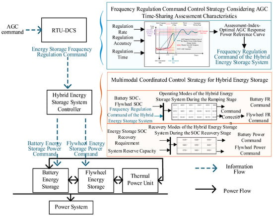
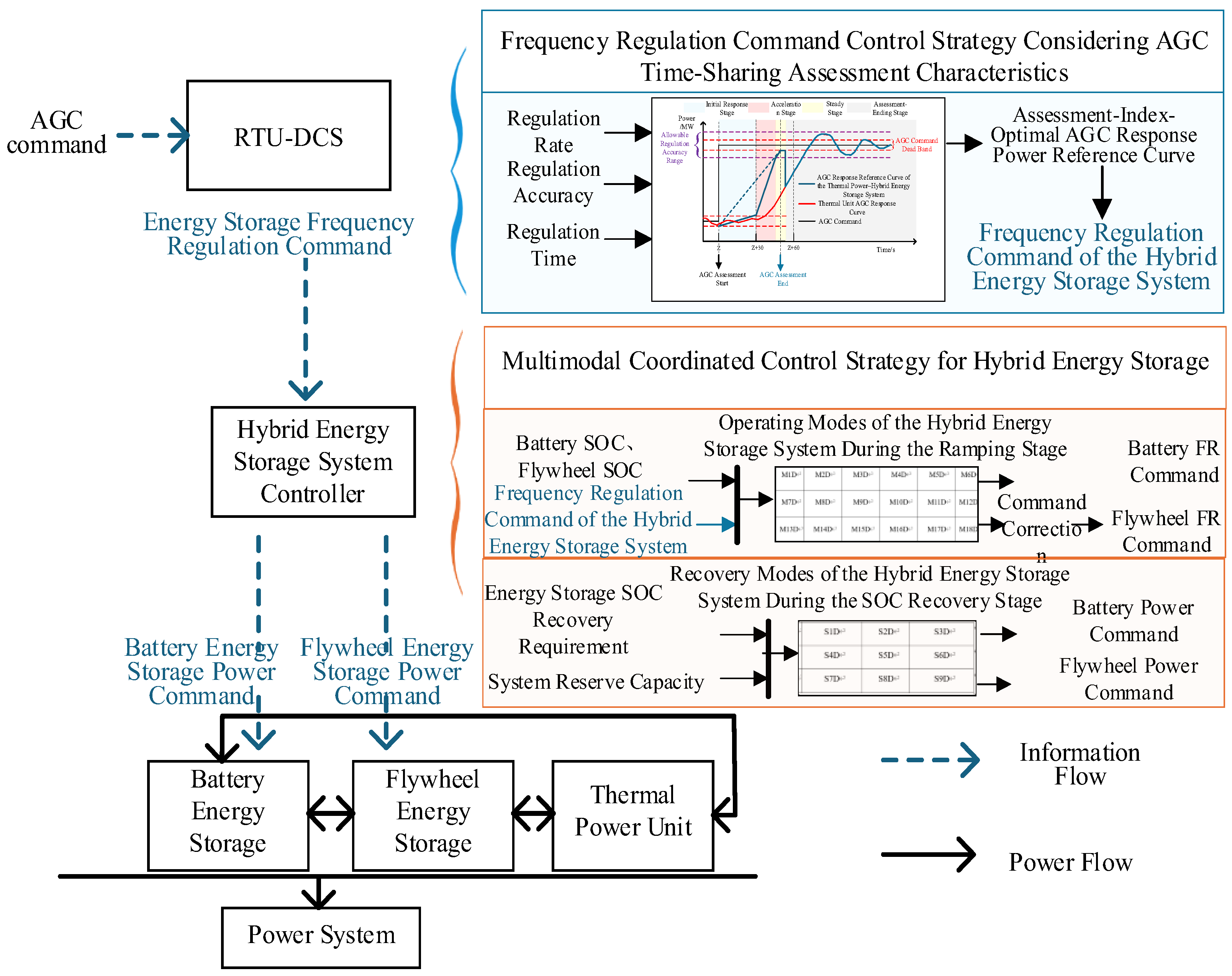
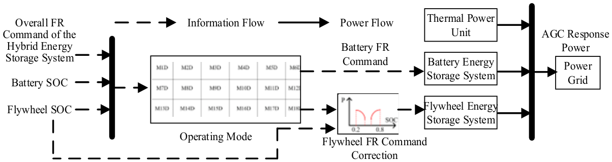
The framework of the joint frequency regulation control strategy for the TP–hybrid ES system proposed in this paper is shown in Figure 1.
Figure 1.
Framework of the joint AGC frequency regulation control strategy for the TP–hybrid ES system.
The proposed control framework consists of two main steps.
First, a frequency regulation command control strategy considering AGC time-sharing assessment characteristics is developed to obtain the frequency regulation command of the hybrid ES system. The purpose of this strategy is to optimize the frequency regulation assessment indices of the joint AGC response curve of the TP–hybrid ES system and reduce ineffective charging and discharging behaviors of the hybrid ES system. Specifically, according to the AGC assessment indices, the AGC response power reference curve that satisfies the optimal assessment requirements is calculated. Then, based on the real-time output curve of the TP unit, the overall frequency regulation command of the hybrid ES system is obtained.
Second, a multimodal coordinated control strategy for the hybrid ES system is proposed to allocate the power commands of different types of ES devices and control the operating power of the hybrid ES system, thereby improving the AGC response performance and frequency regulation sustainability of the TP–hybrid ES system. First, based on the joint AGC response curve of the TP–hybrid ES system that satisfies the optimal assessment indices, the ES ramping period and the AGC non-assessment period in each AGC assessment process are identified. Then, during the ramping period, a multimodal coordinated control strategy for hybrid ES is proposed according to the SOC states of different types of ES systems. This strategy reduces the life degradation of the battery ES system, prevents the flywheel ES system from frequently exceeding its safe operating range, and improves the frequency regulation sustainability of the hybrid ES system. Furthermore, during the AGC non-assessment period, a hybrid ES output control strategy for the SOC recovery stage is proposed according to the system reserve resources. This strategy restores the SOC states of different types of ES systems and further improves the frequency regulation performance and sustainability of the hybrid ES system.
2.2. Frequency Regulation Command Control Strategy for the Hybrid ES System Considering AGC Time-Sharing Assessment Characteristics
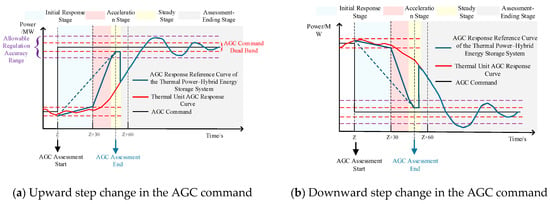
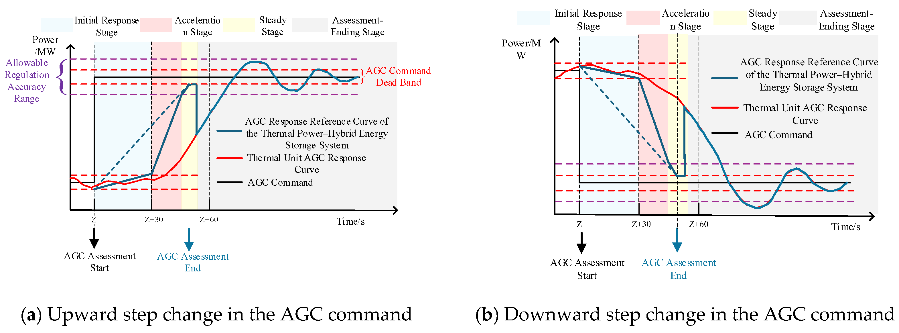
To ensure the optimal AGC response performance of the TP–hybrid ES system, reduce ineffective charging and discharging behaviors of the hybrid ES system, and decrease frequency regulation energy consumption, the reference curve of the joint AGC response power output of the TP–hybrid ES system is shown in Figure 2.
Figure 2.
Assessment-index-oriented optimal reference curve of the joint AGC response power output of the TP–hybrid ES system.
For each AGC command interval, the complete response process is divided into an assessment-active period and a non-assessment period. The assessment-active period starts when a new AGC command is issued and includes the initial response, acceleration, and steady regulation stages, during which the joint output trajectory directly affects the regulation-rate, regulation-time, and regulation-accuracy indices. Once the assessment requirements of the current command have been satisfied, the system enters the assessment-ending stage, which corresponds to the non-assessment period and lasts until the next AGC command arrives. During this stage, additional ES output no longer improves the assessment result of the completed command, and the control objective therefore changes from AGC tracking to SOC restoration and reserve preparation. Accordingly, the four stages are not an arbitrary time segmentation but correspond to the successive objectives of valid response, rapid ramping, accurate settling, and post-assessment state restoration. When the latest AGC command changes upward, namely > , the reference power output models for the optimal AGC response process in different stages are as follows.
- (1)
- Initial response stage
In this stage, the AGC response needs to leave the dead band of the previous AGC command. ES assists the TP unit in leaving the AGC command deadband more quickly. However, the ES output should not be too large; otherwise, the regulation time of the current command may be shorter than 30 s, resulting in an invalid assessment. Therefore, in the initial response stage, the ES system is set to assist the TP unit in ramping slowly and to reach the upper boundary of the AGC command deadband at the minimum regulation time.
where is the value of the joint AGC response power output reference curve of the TP–hybrid ES system at time t; is the joint frequency regulation output of the TP–hybrid ES system when the z-th AGC command changes; is the (z − 1)-th AGC command; and is the AGC response slope of the TP–hybrid ES system in the initial response stage when the latest AGC command changes upward.
- (2)
- Acceleration stage
In this stage, the AGC response enters the rapid ramping process. To optimize the assessment values of regulation rate and regulation time, namely and , the ES system performs rapid and large-amplitude power regulation.
where is the upper boundary of the dead band of the (z − 1)-th AGC command; is the AGC response slope of the TP–hybrid ES system in the acceleration stage when the latest AGC command changes upward; where is the upper limit coefficient of the regulation rate during the acceleration stage. A value that is too small restricts the rapid-response capability of the TP–hybrid ES system, whereas an excessively large value increases the required ES power and energy throughput without necessarily providing further improvement in the AGC assessment indices. Considering the trade-off between regulation performance and ES utilization, is adopted as the baseline value. Its sensitivity is further examined in Section 4.3.1.
- (3)
- Steady stage
In this stage, the AGC response enters a moderate ramping process. To optimize the assessment value of regulation accuracy, namely , the action amplitude of the ES system should be reduced. The joint AGC response power output curve of the TP–hybrid ES system should be maintained within a certain range, that is, within the allowable regulation accuracy range shown in Figure 2.
where is the initial output of the TP–hybrid ES system in the acceleration stage when the latest AGC command changes upward; and is the AGC response slope in the moderate ramping stage.
- (4)
- Assessment-ending stage
In this stage, the AGC assessment is completed, and the ES system exits frequency regulation.
where Δt(z) is the duration of the z-th AGC command.
Similarly, when the latest AGC command changes downward, namely , the reference power output model for the optimal AGC response process in each stage can be obtained in the same manner.
Therefore, the AGC reference command of the hybrid ES system is expressed as
where is the AGC reference command of the hybrid ES system.
3. Multimodal Coordinated Control Strategy for the Hybrid ES System
According to the previous section, during the four stages of the AGC response process of the TP–hybrid ES joint frequency regulation system, the initial response stage, acceleration stage, and steady stage correspond to the period in which the ES system assists the TP unit in ramping, namely the ramping stage. The assessment-ending stage corresponds to the period in which the ES system exits frequency regulation.
During the ramping stage, the SOC states of different types of ES are considered, and a multimodal coordinated control strategy for the hybrid ES system is proposed. This strategy aims to reduce the life degradation of the battery ES system, extend its operating life, prevent the flywheel ES system from frequently exceeding its safe operating range, and improve the frequency regulation sustainability of the hybrid ES system. First, the operating mode of the hybrid ES system is determined according to the SOC states of the flywheel ES system and the battery ES system. Then, based on the magnitude and direction of the overall AGC reference command of the hybrid ES system obtained in the previous section, the frequency regulation commands of different types of ES devices are reasonably allocated. Subsequently, the command is corrected according to the SOC states of the ES devices. Finally, the frequency regulation commands of each ES system during the ramping stage are obtained to control the frequency regulation action of the hybrid ES system.
During the assessment-ending stage, the primary objective of each type of ES is to recover its SOC to the desired state. Therefore, this paper proposes a multimodal coordinated control strategy for the SOC recovery stage of the hybrid ES system considering system reserve resources. By utilizing the capacity of the TP unit and the remaining capacity of the ES devices, the SOC recovery of different types of ES systems can be achieved without affecting the AGC assessment indices, thereby improving the AGC response performance and sustainability of the TP–hybrid ES system in the ramping stage. First, the recovery mode of the hybrid ES system is determined according to the SOC recovery requirements of the flywheel ES system and the battery ES system. Then, the coordinated control strategy for each ES device is determined according to the SOC recovery model and the system reserve capacity. Therefore, SOC is treated in the proposed strategy as a dynamic control variable that determines power-allocation mode, boundary correction, and post-assessment recovery, rather than merely as a passive upper/lower operating constraint.
3.1. Multimodal Coordinated Control Strategy for the Hybrid ES System During the Ramping Stage
During the ramping stage, the hybrid ES system needs to respond rapidly to the frequency regulation requirement according to the overall AGC reference command. The battery ES system has a relatively large energy capacity, but its cycle life is sensitive to the depth of charge and discharge; therefore, its SOC range is divided into prohibited, limited, and adjusted charging/discharging regions. The outer thresholds of 0.2 and 0.8 are used as the lower and upper protection boundaries, respectively, while the intervals of 0.20–0.25 and 0.75–0.80 provide transition margins before the corresponding prohibited regions are reached. The intermediate intervals of 0.25–0.55 and 0.55–0.75 are used for discharge- and charge-oriented power adjustment, respectively. In contrast, the flywheel ES system has a high cycling capability and fast response but a relatively small energy capacity. Its SOC is therefore classified into a low-SOC protection region [0, 0.2], a normal response region [0.2, 0.8], and a high-SOC protection region [0.8, 1]. Based on these SOC thresholds, the six battery states and three flywheel states form the 18 operating modes listed in Table 1.
Table 1.
Operating modes of hybrid ES systems.
The 18 operating modes listed in Table 1 reflect the charging and discharging capability of the battery ES system and the flywheel ES system under different SOC combinations. Among them, boundary modes such as M1D, M6D, M13D, and M18D are mainly used to prevent overcharging or overdischarging of the ES system. Modes such as M8D, M9D, M11D, and M12D are mainly used to reduce the charge and discharge depth of the battery when its SOC approaches the boundary. In normal modes such as M10D, both the battery ES system and the flywheel ES system have sufficient charging and discharging capability and can jointly participate in AGC frequency regulation. These values are control-design thresholds rather than fixed physical limits, and their sensitivity is further examined in Section 4.3.2.
Let the overall AGC reference command of the hybrid ES system at time be expressed as
where is the overall frequency regulation reference command of the hybrid ES system; is the joint AGC reference output of the TP–hybrid ES system obtained after considering AGC time-sharing assessment characteristics; and is the real-time output of the TP unit. In this paper, indicates that the hybrid ES system needs to discharge to compensate for the insufficient ramping capability of the TP unit, whereas indicates that the hybrid ES system needs to charge to absorb surplus power output.
Let the frequency regulation power commands of the battery ES system and the flywheel ES system be and , respectively. During the ramping stage, they should satisfy
where denotes the uncompensated power caused by ES power constraints or SOC constraints. When the hybrid ES capacity is sufficient, . When both the battery ES system and the flywheel ES system are constrained, the uncompensated part is subsequently regulated by the TP unit.
To reflect the fast response characteristics of the flywheel ES system, the basic allocation principle of “flywheel priority and battery compensation” is adopted during the ramping stage. That is, when , the flywheel ES system preferentially discharges to provide the fast power component, and the battery ES system supplies the remaining power. When , the flywheel ES system preferentially charges to absorb the fast power component, and the battery ES system provides supplementary absorption according to its SOC state.
When , the hybrid ES system operates in the discharging frequency regulation state, and the power allocation is expressed as
When , the hybrid ES system operates in the charging frequency regulation state, and the power allocation is expressed as
where and are the available charging and discharging powers of the battery ES system at time t, respectively; and are the available charging and discharging powers of the flywheel ES system at time t, respectively; and are the discharging and charging SOC correction coefficients of the battery ES system, respectively; and and are the discharging and charging SOC correction coefficients of the flywheel ES system, respectively.
The available charging and discharging powers of the two types of ES are jointly determined by the rated power constraints and the SOC energy margin, which can be expressed as
where denotes the battery ES system or the flywheel ES system; and are the maximum discharging power and maximum charging power of the i-th type of ES, respectively; is the rated capacity of the ES system; and are the lower and upper SOC operating limits of the ES system, respectively; and Δt is the control step.
Since long-term overcharging or overdischarging during AGC frequency regulation will aggravate the life degradation of the battery ES system, an S-shaped smoothing function is introduced to correct the battery power command and prevent the battery from still undertaking large frequency regulation power when its SOC approaches the upper or lower limit.
The discharging correction coefficient of the battery is defined as
The charging correction coefficient of the battery is defined as
where and are the slope coefficients of the battery discharging and charging correction functions, respectively; and and are the center points of the discharging and charging corrections, respectively. As indicated by Equations (21) and (22), when the battery SOC approaches the lower limit, the discharging correction coefficient gradually decreases, thereby restricting further discharging of the battery. When the battery SOC approaches the upper limit, the charging correction coefficient gradually decreases, thereby restricting further charging of the battery. When the battery SOC is within an appropriate range, the correction coefficient approaches 1, allowing the battery ES system to fully participate in frequency regulation.
The flywheel ES system has the advantages of fast response speed and long cycle life, making it suitable for providing the fast-changing power component in the AGC command. However, the energy capacity of the flywheel is relatively small. If its SOC frequently approaches the upper or lower boundary, its subsequent frequency regulation capability will be reduced. To prevent the flywheel ES system from frequently exceeding its safe operating range, a quadratic function is introduced to correct the flywheel power command.
The discharging correction coefficient of the flywheel is defined as
The charging correction coefficient of the flywheel is defined as
where and are the safety thresholds for the discharging and charging corrections of the flywheel ES system, respectively. According to Equations (23) and (24), when the flywheel SOC approaches the lower limit, its discharging capability gradually decreases; when the flywheel SOC approaches the upper limit, its charging capability gradually decreases. Through this correction mechanism, the flywheel ES system can preferentially provide fast frequency regulation power within the safe SOC range, while avoiding degradation of subsequent response capability caused by frequent boundary contact.
These closed-form correction functions provide deterministic and computationally simple SOC-to-power mappings without introducing an additional online optimization layer. Their parameters are linked to the SOC operating regions defined in Table 1 and are treated as control-design parameters rather than parameters fitted to a specific operating trajectory. The corresponding parameter sensitivity is examined in Section 4.3.2.
All operating modes in Table 1 can be described by the unified model in Equations (15)–(20). For example, when the system is in M1D and receives a discharging command, both the battery ES system and the flywheel ES system are in the low-SOC region, and their available discharging power or discharging correction coefficient is zero; therefore, neither device discharges. When the system is in M10D, both the battery and flywheel ES systems are within appropriate SOC ranges. In this case, the flywheel preferentially provides the fast power component, while the battery supplies the remaining frequency regulation power. When the system is in M18D and receives a charging command, both types of ES are close to their SOC upper limits, and the charging correction coefficient is zero; therefore, the hybrid ES system stops charging to prevent overcharging.
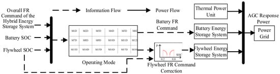
In summary, during the ramping stage of the ES system, the multimodal coordinated control strategy is adopted to optimize ES output, and its control framework is shown in Figure 3. The multimodal coordinated control strategy realizes the allocation and correction of frequency regulation commands. It not only accounts for the SOC state of the battery ES system and improves battery life, but also prevents the flywheel ES system from frequently exceeding its safe operating range, thereby improving the frequency regulation sustainability of the hybrid ES system.
Figure 3.
Multi-modal coordinated control strategy for hybrid ES systems during the ramping stage.
3.2. Multimodal Coordinated Control Strategy for the Hybrid ES System During the SOC Recovery Stage
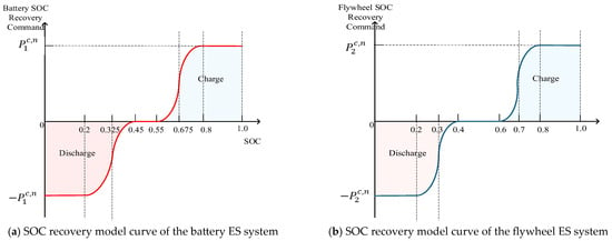
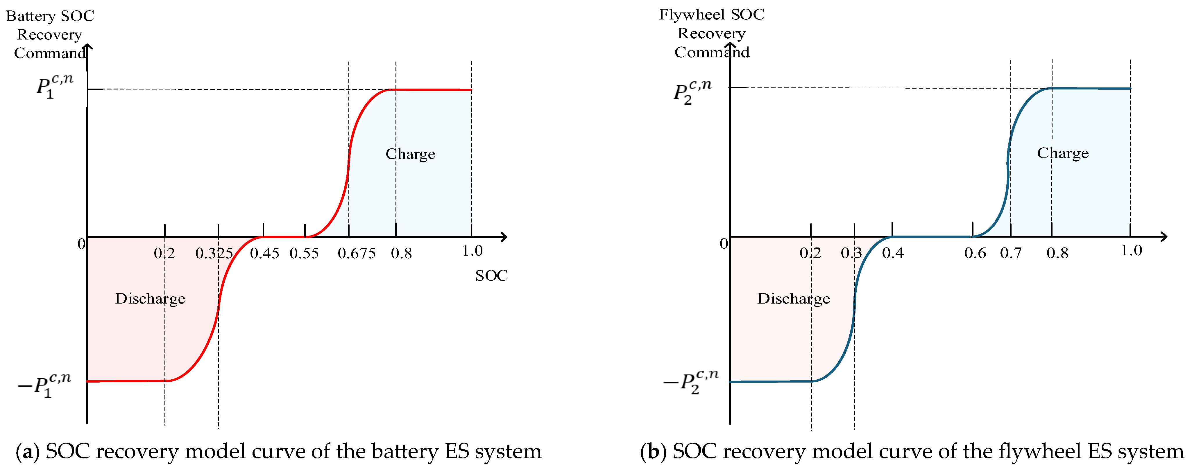
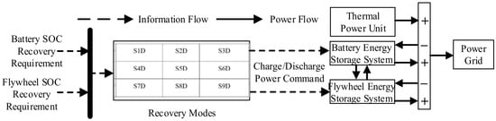
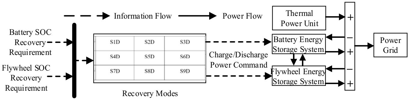
In this paper, a logistic regression function is introduced to construct the SOC recovery models of the flywheel and battery ES systems. The corresponding model curves are shown in Figure 4.
Figure 4.
SOC recovery model curves of ES systems.
The ES power expressions during the SOC recovery stage are as follows:
where and are the power values of the battery ES system and the flywheel ES system during the SOC recovery stage, respectively.
According to the SOC recovery requirements of the two types of ES systems, the recovery modes of the hybrid ES system are obtained, as shown in Table 2. The SOC recovery control models for different modes are as follows.
Table 2.
Mixed ES system recovery mode.
- (1)
- S1D
When the ES system is in S1D, both the flywheel and the battery require system reserve capacity for SOC recovery. In this case, reducing the frequency regulation output of the conventional unit will not affect the AGC assessment result. Therefore, the real-time frequency regulation output capacity of the TP unit is activated, and the battery is prioritized to recover to its desired SOC state. The corresponding ES power commands are
where and are the power commands of the battery ES system and the flywheel ES system during the SOC recovery stage, respectively.
- (2)
- S2D
When the ES system is in S2D, the battery is in its desired SOC state, and only the flywheel has a charging demand. In this case, the real-time frequency regulation output capacity of the TP unit is called to restore the flywheel to its desired SOC state. The corresponding ES power commands are
- (3)
- S3D
When the ES system is in S3D, the battery has a discharging demand, whereas the flywheel has a charging demand. In this case, the battery capacity is first used to restore the flywheel to its desired SOC state. If the energy required for the flywheel to recover to its desired SOC state is relatively large, the battery stops discharging when it reaches its desired SOC state, and the real-time frequency regulation capacity of the TP unit is then used to continue restoring the flywheel to its desired SOC state. If the energy required for flywheel recovery is relatively small, after the battery discharges to restore the flywheel to its desired SOC state, the battery continues to discharge to the TP unit until the battery itself recovers to its desired SOC state, because increasing the output of the TP–hybrid ES system at this time does not affect the AGC assessment result. The corresponding ES power commands are
- (4)
- S4D
When the ES system is in S4D, the flywheel is in its desired SOC state, and only the battery has a charging demand. In this case, the real-time frequency regulation output capacity of the TP unit is called to restore the battery to its desired SOC state. The corresponding ES power commands are
- (5)
- S5D
When the ES system is in S5D, both the flywheel and the battery are in their desired SOC states. The corresponding ES power commands are
- (6)
- S6D
When the ES system is in S6D, the flywheel is in its desired SOC state, and only the battery has a discharging demand. Since increasing the output of the TP–hybrid ES system does not affect the AGC assessment result at this time, the battery discharges to the TP unit until it recovers to its desired SOC state. The corresponding ES power commands are
- (7)
- S7D
When the ES system is in S7D, the flywheel has a discharging demand, whereas the battery has a charging demand. In this case, the flywheel capacity is first used to restore the battery to its desired SOC state. If the energy required for the battery to recover to its desired SOC state is relatively large, the flywheel stops discharging when it reaches its desired SOC state, and the real-time frequency regulation capacity of the TP unit is then used to continue restoring the battery to its desired SOC state. If the energy required for battery recovery is relatively small, after the flywheel discharges to restore the battery to its desired SOC state, the flywheel continues to discharge to the TP unit until the flywheel itself recovers to its desired SOC state, because increasing the output of the TP–hybrid ES system at this time does not affect the AGC assessment result. The corresponding ES power commands are
- (8)
- S8D
When the ES system is in S8D, the flywheel has a discharging demand, and the battery is in its desired SOC state. In this case, the flywheel discharges to the TP unit until it recovers to its desired SOC state. The corresponding ES power commands are
- (9)
- S9D
When the ES system is in S9D, both the flywheel and the battery have discharging demands. In this case, both the flywheel and the battery discharge to the TP unit until the battery recovers to its desired SOC state. The corresponding ES power commands are
In summary, through the multimodal coordinated control strategy for the hybrid ES system during the SOC recovery stage, as shown in Figure 5, the capacity of the TP unit and the remaining capacity of the ES devices are utilized to achieve SOC recovery of different types of ES systems without affecting the AGC assessment indices. Compared with relying solely on ES capacity or TP reserve, the proposed strategy can improve the degree of SOC recovery of the ES system and enhance the AGC response performance and sustainability of the TP–hybrid ES system during the ramping stage.
Figure 5.
Multimodal coordinated control strategy for the hybrid ES system during the SOC recovery stage.
4. Case Study
Based on the AGC command data and actual AGC response power operation data of a typical month from a TP plant in Hubei Province, the effectiveness and superiority of the proposed hybrid ES control strategy are verified. The case parameters are given in Ref. [26]. The rated capacities of the battery ES system and the flywheel ES system are set to 2.0 MWh and 0.2 MWh, respectively. Four different schemes are designed for comparison with the proposed scheme: no flywheel ES, denoted as Scheme I; full compensation combined with the multimodal coordinated control strategy for the hybrid ES system, denoted as Scheme II; the frequency regulation command control strategy for the hybrid ES system considering AGC time-sharing assessment characteristics combined with proportional allocation, denoted as Scheme III; and the frequency regulation command control strategy for the hybrid ES system considering AGC time-sharing assessment characteristics combined with the ramping-stage multimodal coordinated control strategy for the hybrid ES system, denoted as Scheme IV.
These comparison schemes are also used for component-wise ablation. Specifically, Scheme II and the proposed scheme are compared to evaluate the contribution of AGC time-sharing assessment; Scheme III and Scheme IV are compared to evaluate the contribution of ramping-stage multimodal coordination; and Scheme IV and the proposed scheme are compared to evaluate the contribution of the SOC recovery strategy. Scheme I is retained as an auxiliary comparison between single battery storage and hybrid battery–flywheel storage.
4.1. Comparative Analysis of Frequency Regulation Performance
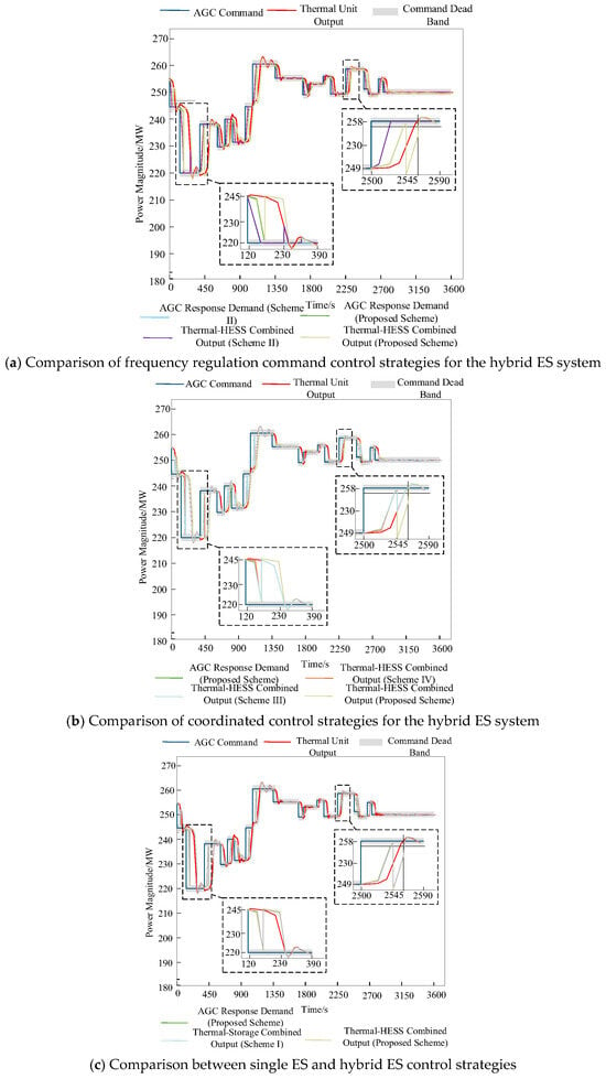
The AGC response curves of frequency regulation resources under the five schemes are shown in Figure 6. Compared with full compensation, the frequency regulation demand of the ES system is lower when AGC time-sharing assessment characteristics are considered. This reduces the output of ES during the ramping stage and avoids unnecessary output beyond the frequency regulation assessment period. Compared with proportional allocation, after the multimodal coordinated control strategy for the hybrid ES system is adopted, the TP unit output fluctuates in the non-assessment region because of the SOC recovery of the ES system; however, this does not affect AGC assessment. Compared with the case without SOC recovery, the frequency regulation demand tracking deviation is smaller under the multimodal coordinated control strategy for the hybrid ES system during the SOC recovery stage. In particular, when the AGC command changes significantly, the hybrid ES system needs to provide a larger output capacity. Without SOC recovery, it is difficult for the system to reserve sufficient response capacity for the next frequency regulation demand. Compared with the use of only battery ES, the hybrid ES system can provide a larger AGC response capacity, thereby reducing the frequency regulation demand tracking deviation of the TP–hybrid ES system.
Figure 6.
Comparison of AGC response curves of frequency regulation resources within one hour under different schemes.
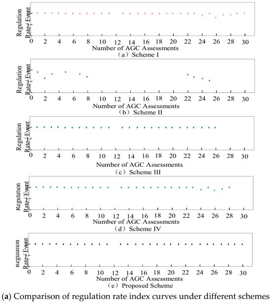
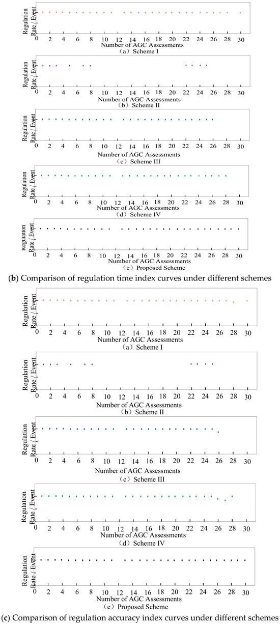
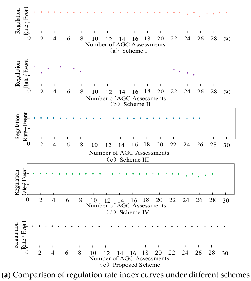
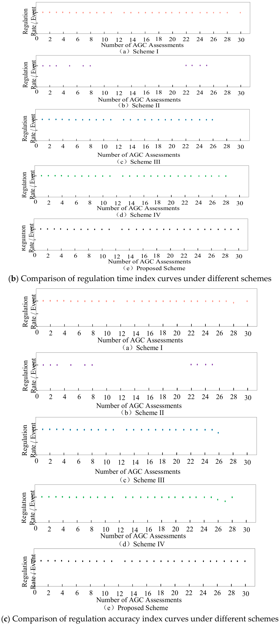
Table 3 and Figure 7 compare the frequency regulation performance indices of the five schemes. The proposed scheme achieves the highest average regulation rate, regulation time, regulation accuracy, and comprehensive evaluation indices, together with the highest assessment success rate of 99%. These results verify the overall effectiveness of the proposed strategy in improving the auxiliary frequency regulation performance of the TP unit.
Table 3.
Comparison of average frequency regulation performance indicators under different schemes.
Figure 7.
Comparison of frequency regulation index curves under different schemes within a 2 h assessment period.
From the component-wise ablation perspective, the three control modules provide different contributions to the overall regulation performance. First, replacing the full-compensation strategy in Scheme II with AGC time-sharing assessment increases the comprehensive evaluation index from 0.32 to 1.91 and the assessment success rate from 57% to 99%, indicating that avoiding ineffective compensation outside the valid assessment process is the dominant factor in improving assessment effectiveness. Second, replacing proportional allocation in Scheme III with the ramping-stage multimodal coordination in Scheme IV increases the comprehensive index from 1.21 to 1.26 and the assessment success rate from 81% to 87%. Although this improvement is moderate, it is accompanied by smoother SOC behavior and reduced high-power battery operation. Finally, introducing SOC recovery on the basis of Scheme IV further increases the comprehensive index from 1.26 to 1.91 and the assessment success rate from 87% to 99%, confirming that restoring the storage states after assessment improves the availability of the hybrid ES system for subsequent AGC events.
4.2. Comparative Analysis of Frequency Regulation Benefits
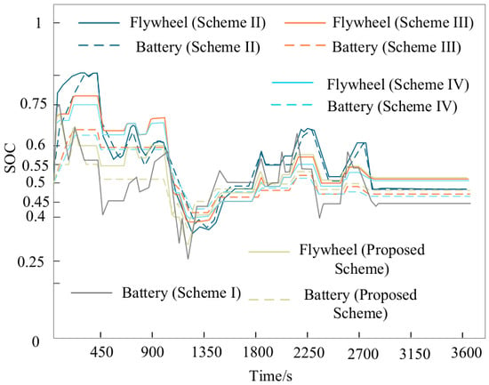
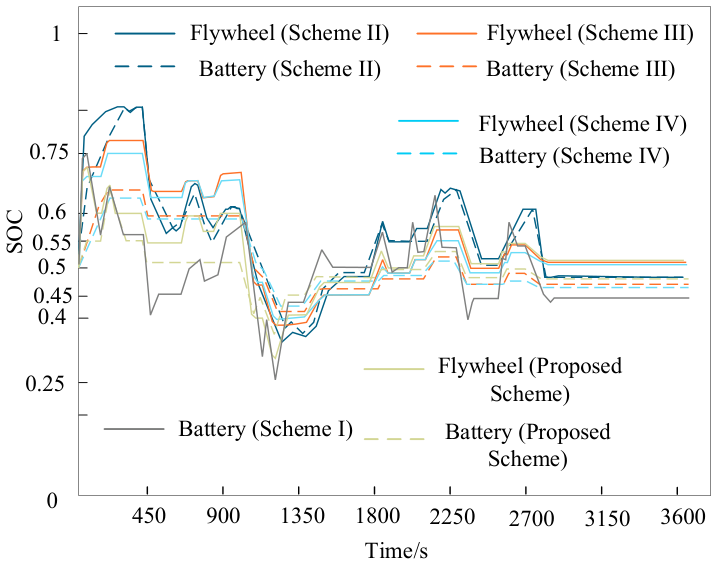
Figure 8 shows the SOC variation curves of the hybrid ES system under the five schemes.
Figure 8.
Comparison of SOC curves of the hybrid ES system within one hour under different schemes.
Compared with full compensation, the frequency regulation command control strategy for the hybrid ES system considering AGC time-sharing assessment characteristics reduces the output during the ramping stage and unnecessary output during the non-assessment period. It increases the duration for which each type of ES remains in its desired SOC state and reduces the variation amplitude of the SOC curves. Compared with proportional allocation, the SOC curves of the ES system under the ramping-stage multimodal coordinated control strategy for the hybrid ES system vary more smoothly, without frequent high-power charging and discharging. Compared with the case without SOC recovery, after the multimodal coordinated control strategy for the hybrid ES system during the SOC recovery stage is adopted, the durations for which both the battery and flywheel ES systems remain in their desired SOC states are increased. Compared with the use of only battery ES, after hybrid ES is adopted, the frequency regulation output of the battery is reduced, and the duration for which the battery remains in its desired SOC state is increased.
Table 4 compares the frequency regulation economic parameters of the five schemes. Compared with Scheme II, introducing AGC time-sharing assessment increases the AGC reward by 7.09 million yuan, reduces the frequency-regulation energy-consumption cost by 2.01 million yuan and the life-degradation cost by 0.35 million yuan, and, consequently, increases the net benefit by 9.45 million yuan. Compared with Scheme III, the ramping-stage multimodal coordination in Scheme IV reduces the energy-consumption cost by 0.31 million yuan and the life-degradation cost by 0.04 million yuan, while increasing the net benefit by 0.51 million yuan. Finally, adding SOC recovery to Scheme IV increases the AGC reward by 1.70 million yuan, reduces the energy-consumption cost by 0.22 million yuan and the life-degradation cost by 0.20 million yuan, and increases the net benefit by 2.12 million yuan. These comparisons show that AGC time-sharing mainly improves assessment effectiveness and avoids unnecessary ES operation, ramping-stage multimodal coordination mainly reduces intensive battery utilization, and SOC recovery mainly improves subsequent regulation availability and long-term operating sustainability. The reductions in energy consumption and degradation costs, together with the smoother SOC trajectories in Figure 8, further demonstrate that AGC time-sharing effectively suppresses unnecessary ES operation after the current assessment requirement has been satisfied.
Table 4.
Comparison of frequency regulation’s economic performance under different schemes.
In summary, the proposed scheme shows clear superiority in terms of frequency regulation economics. On the one hand, the proposed control strategy improves frequency regulation performance, increases the duration for which the ES system remains in its desired SOC state, increases AGC reward revenue, and reduces the frequency regulation energy consumption and battery life degradation costs. On the other hand, by adopting hybrid ES, battery life degradation is reduced, which further improves the economic performance of frequency regulation.
4.3. Sensitivity and Robustness Analysis
4.3.1. Sensitivity Analysis of the Four-Stage AGC Response
To further examine the rationality and parameter robustness of the four-stage AGC response strategy, stage-specific sensitivity tests were conducted while keeping the remaining control parameters unchanged. The initial-response duration, acceleration-rate limit, and steady-stage smoothing duration were varied around their baseline values. Since the first three stages directly participate in the current AGC assessment, the comprehensive regulation index and battery energy throughput were used as the main evaluation indices. In contrast, the assessment-ending stage occurs after completion of the current AGC assessment; therefore, its effectiveness was evaluated using SOC restoration capability under different available thermal-reserve conditions. The main results are summarized in Table 5.
Table 5.
Sensitivity results of the four-stage AGC response strategy. Panel (A): sensitivity results for Stages I–III. Panel (B): SOC-restoration sensitivity in the assessment-ending stage.
(The results at 2 and 4 MW coincide with the corresponding plateau values at 1–8 MW and are omitted for conciseness.)
For the initial response stage, was varied from 25 to 35 s. Taking 30 s as the baseline, reducing the duration to 25 s increases the average comprehensive regulation performance by 5.62%, but increases the battery energy throughput by 48.59%. Increasing it to 35 s reduces the battery throughput by 21.29%, but decreases the regulation performance by 5.96%. Therefore, the 30 s setting provides a reasonable compromise between maintaining a valid assessment duration, regulation performance, and battery utilization intensity. For the acceleration stage, was varied between 1.5 and 2.5. When it decreases from 2 to 1.5, the normalized regulation performance decreases by approximately 4.97%. In contrast, increasing from 2 to 2.5 provides almost no further performance improvement, while the battery throughput increases by approximately 9.95%. This indicates that is located near the performance plateau and avoids unnecessary battery utilization caused by an excessively high acceleration rate. For the steady regulation stage, the smoothing duration was varied from 2 to 4 s. The normalized comprehensive regulation performance remains within 0.9971–1.0036, while the normalized battery throughput remains within 0.9733–1.0358. Therefore, the response is relatively insensitive to moderate variations in the steady-stage smoothing duration, indicating that the baseline value of 3 s lies within a stable operating range.
The assessment-ending stage has a different objective from the first three stages because the current AGC assessment has already been completed. Therefore, its sensitivity is evaluated using SOC restoration rather than current-event . For low-SOC charging recovery, increasing the available thermal reserve from 0 to 0.5 MW increases the BESS SOC-recovery ratio from 0 to 25%, and the ratio reaches approximately 27% when the reserve is at least 1 MW. Owing to its smaller energy capacity, the flywheel can recover from a low SOC to its desired range within the same recovery window once 0.5 MW of reserve is available. For high-SOC conditions, SOC restoration is achieved mainly through storage discharging and is therefore much less dependent on the available thermal reserve. These results confirm that the assessment-ending stage provides a post-assessment state-restoration mechanism and improves the readiness of the hybrid ES system for the subsequent regulation task.
4.3.2. Sensitivity Analysis of SOC Thresholds and Nonlinear Correction Parameters
The influence of the SOC protection thresholds was further examined by shifting the outer SOC boundaries while keeping the remaining control parameters unchanged. A positive offset denotes a more conservative setting, i.e., the low-SOC protection thresholds are shifted upward and the high-SOC protection thresholds are shifted downward. Representative upward and downward AGC events were used to activate the corresponding low- and high-SOC operating regions. The results are listed in Table 6.
Table 6.
Representative sensitivity results of SOC thresholds and nonlinear correction parameters. Panel (A): SOC protection thresholds. Panel (B): battery S-shaped correction. Panel (C): flywheel nonlinear correction.
As shown in Table 6, the SOC-protection threshold mainly affects the regulation capability when the storage device operates close to the corresponding boundary. Under upward regulation, making the low-SOC protection more conservative increases the target-entry time from 62 to 124 s and markedly reduces , whereas the downward-regulation performance is much less sensitive to the tested threshold variation. This indicates that excessively conservative SOC protection may sacrifice the available regulation capability, particularly on the low-SOC discharge side.
The nonlinear correction parameters show different sensitivity characteristics. The battery S-shaped correction is relatively insensitive to moderate changes in its slope: varying from 0.5 to 2 results in only minor changes in and battery throughput. In contrast, the flywheel correction reflects a clearer trade-off between rapid response and SOC-margin preservation. A weaker correction improves short-term regulation performance but uses more flywheel SOC margin, whereas an excessively strong correction significantly restricts the flywheel response. Therefore, the baseline parameters are selected as balanced control settings rather than strict mathematical optima.
The proposed controller is parameterized by the real-time thermal-unit output, unit-specific regulation capability, available reserve, and ES power/energy limits rather than by a fixed AGC trajectory. Therefore, its control structure can be retained when applied to other thermal units by updating the corresponding unit-specific parameters. Nevertheless, quantitative regulation and economic performance may vary with the operating point, AGC-command characteristics, reserve conditions, seasonal conditions, and regional assessment rules. Further validation using multi-season and multi-plant field data will be considered in future work.
5. Conclusions
To address the unreasonable control strategies currently used for joint frequency regulation of TP units and hybrid ES systems, this paper proposes a joint frequency regulation control strategy considering AGC time-sharing assessment characteristics and multimodal coordination. A frequency regulation command control strategy for the hybrid ES system considering AGC time-sharing assessment characteristics is designed to obtain the hybrid ES frequency regulation reference command that optimally satisfies the AGC assessment indices. In addition, a multimodal coordinated control strategy for the hybrid ES system is proposed, including a ramping-stage multimodal coordinated control strategy and an SOC recovery-stage multimodal coordinated control strategy. Based on the available reserve capacity of the system and the SOC states of the ES devices, the power commands of different types of ES are reasonably controlled, thereby improving the AGC response performance and frequency regulation sustainability of the TP–hybrid ES system. The following conclusions are obtained through simulation case studies.
- (1)
- Compared with the commonly used full-compensation and proportional allocation control strategies, the proposed control strategy can effectively improve AGC assessment indices and frequency regulation benefits. In terms of frequency regulation performance, the frequency regulation command control strategy for the hybrid ES system considering AGC time-sharing assessment characteristics can avoid the situation in which the regulation time is shorter than the minimum assessment requirement under the conventional full-compensation strategy. This reduces the assessment failure rate and improves the frequency regulation indices. Meanwhile, the multimodal coordinated control strategy for the hybrid ES system enhances frequency regulation sustainability and further improves the regulation indices. In terms of economic performance, the proposed control strategy improves frequency regulation performance, increases the duration for which the ES system remains in its desired SOC state, increases AGC reward revenue, and reduces both frequency regulation energy consumption and battery life degradation.
- (2)
- The use of hybrid ES to assist TP units in frequency regulation shows clear advantages. It comprehensively improves regulation performance and economic benefits, reduces battery life degradation, and increases the net benefit of frequency regulation.
Author Contributions
Conceptualization, R.L., Q.L., S.L., and Q.W.; methodology, R.L., Q.L., S.L., and Q.W.; software, R.L., Q.L., S.L., and Q.W.; formal analysis, R.L., Q.L., S.L., and Q.W.; resources, R.L., Q.L., S.L., and Q.W.; data curation, R.L., Q.L., S.L., and Q.W.; writing—original draft preparation, R.L., Q.L., S.L., and Q.W.; writing—review and editing, R.L., Q.L., S.L., and Q.W.; visualization, R.L., Q.L., S.L., and Q.W. All authors have read and agreed to the published version of the manuscript.
Funding
This research received no external funding.
Data Availability Statement
The original contributions presented in this study are included in the article. Further inquiries can be directed to the corresponding author.
Conflicts of Interest
Author Ruonan Liao was employed by China Three Gorges University. The remaining authors declare that the research was conducted in the absence of any commercial or financial relationships that could be construed as potential conflicts of interest.
References
- Qian, H.; Zhang, L.; Chen, Q. Capacity configuration of integrated thermal power frequency regulation systems based on battery life degradation. Therm. Power Eng. 2018, 33, 128–132. [Google Scholar] [CrossRef]
- Wang, S.; Yan, H.; Li, J.; Zhang, Y.; Ma, H.; Han, Z.; Xu, C. Power distribution strategies for energy storage systems considering battery life in secondary frequency regulation. Clean Coal Technol. 2024, 30, 95–101. [Google Scholar] [CrossRef]
- Yu, H.; Shuai, Y.; Jin, D. Energy storage frequency regulation control strategy based on frequency regulation signal optimization. J. Power Supply 2025, 23, 101–110. [Google Scholar] [CrossRef]
- Zhang, P.; Di, H.; Hu, L.; Xue, Y.; Liu, T. Control strategy for hybrid energy storage participation in secondary frequency regulation based on hierarchical adaptive control. Power Gener. Technol. 2026, 47, 99–110. [Google Scholar] [CrossRef]
- Dai, S.; Wang, K.; Cao, B.; Zhang, X.; Gao, X.; Liu, X. Optimal configuration of hybrid energy storage capacity in thermal power plants based on CEEMDAN power decomposition. J. Electr. Eng. 2024, 19, 57–66. [Google Scholar] [CrossRef]
- Li, X.; Wang, J.; Qiu, Y.; Hou, Y.; Zhou, Q. Optimal configuration of hybrid energy storage capacity based on VMD. J. Sol. Energy 2022, 43, 88–96. [Google Scholar] [CrossRef]
- Zhang, S.; Li, P.; Zhang, Y.; Liu, X. A composite energy storage secondary frequency regulation strategy based on variable filter time constants and fuzzy control. J. Shanghai Jiao Tong Univ. 2025, 59, 1370–1382. [Google Scholar] [CrossRef]
- Makarov, Y.V.; Du, P.; Kintner-Meyer, M.C.W.; Jin, C.; Illian, H.F. Sizing energy storage to accommodate high penetration of variable energy resources. IEEE Trans. Sustain. Energy 2012, 3, 34–40. [Google Scholar] [CrossRef] [Scilit]
- Hu, Z.; Xie, X.; Zhang, F.; Zhang, J.; Song, Y. Research on automatic power generation control strategies involving energy storage resources. China J. Electr. Eng. 2014, 34, 5080–5087. [Google Scholar] [CrossRef]
- Tang, J.; Li, X.; Huang, J.; Xu, P.; He, C. A capacity allocation method for energy storage batteries participating in secondary frequency regulation with the objective of maximizing net benefit. J. Electr. Eng. Technol. 2019, 34, 963–972. [Google Scholar] [CrossRef]
- Jia, Y.; Zheng, J.; Chen, H.; Yan, Z.; Wang, J.; Chang, X. Optimization of frequency regulation energy storage capacity allocation for thermal-storage integrated dispatch based on ensemble empirical mode decomposition. Grid Technol. 2018, 42, 2930–2937. [Google Scholar] [CrossRef]
- Yan, G.; Li, Y.; Sha, Q.; Song, D.; Qiao, X.; Fan, Y.; Shi, M.; Zhang, H. A collaborative control strategy for hybrid energy storage-assisted frequency regulation of thermal power units based on an improved adaptive complete set empirical modal decomposition. Grid Technol. 2026, 50, 210–220. [Google Scholar] [CrossRef]
- Zhang, W.; Wang, W.; Gao, S.; Li, X.; Chen, B.; Fang, F. Control strategy for flywheel energy storage-assisted secondary frequency regulation considering thermal power plant operational stability. J. Power Eng. 2024, 44, 919–929. [Google Scholar] [CrossRef]
- Liu, X.; Liu, L. A battery energy storage-assisted secondary frequency regulation control strategy based on adaptive decomposition of frequency-modulated signals. J. Power Eng. 2024, 44, 590–598, 631. [Google Scholar] [CrossRef]
- He, J.; Shi, C.; Wei, T.; Jia, D. Stochastic Model Predictive Control of Hybrid Energy Storage for Improving AGC Performance of Thermal Generators. IEEE Trans. Smart Grid 2022, 13, 393–405. [Google Scholar] [CrossRef] [Scilit]
- Xing, Z.; Liang, L.; Tian, Y.; Liu, L.; Zuo, C.; Zhu, L.; Li, Z.; Yang, Z.; Kang, J.; Hong, F. Two-Layer Optimal Control Strategy of Thermal Power Unit Coupled With Hybrid Energy Storage System in Frequency Regulation. Energy Sci. Eng. 2026, 14, 1965–1975. [Google Scholar] [CrossRef] [Scilit]
- Xie, X.; Guo, Y.; Wang, B.; Dong, Y.; Mou, L.; Xue, F. Improving AGC Performance of Coal-Fueled Thermal Generators Using Multi-MW Scale BESS: A Practical Application. IEEE Trans. Smart Grid 2018, 9, 1769–1777. [Google Scholar] [CrossRef] [Scilit]
- Cui, H.; Yang, B.; Jiang, Y.; Tan, Z.; Cui, D.; Li, Q. Control strategy for secondary frequency regulation involving fuzzy control and SOC self-recovery energy storage. Power Syst. Prot. Control 2019, 47, 89–97. [Google Scholar] [CrossRef]
- Wang, N.; Li, Z.; Zhou, X.; Liu, C.; An, C.; Cong, L. Joint frequency regulation characteristics and simulation of AGC and energy storage in power plants. Therm. Power Gener. 2021, 50, 148–156. [Google Scholar] [CrossRef]
- Sun, B.; Liu, Z.; Yang, S.; Wang, R.; Li, T. Real-time optimization of compensation degree in the energy storage–thermal power combined AGC strategy. Grid Technol. 2018, 42, 426–433. [Google Scholar] [CrossRef]
- Cao, D.; Yao, L.; Liao, S.; Xu, J.; Mao, B.; Xie, B. A Coordinated Control Strategy of Flywheel-Battery Hybrid Energy Storage System for Participating in Grid Frequency Regulation. In Proceedings of the 2023 International Conference on Power Energy Systems and Applications (ICoPESA 2023), Nanjing, China, 24–26 February 2023; pp. 283–288. [Google Scholar]
- Wen, S.; Gong, Y.; Zhao, Z.; Mu, X.; Zhao, S. Power Grid Primary Frequency Control Strategy Based on Fuzzy Adaptive and State-of-Charge Self-Recovery of Flywheel-Battery Hybrid Energy Storage System. Energies 2025, 18, 1536. [Google Scholar] [CrossRef] [Scilit]
- Shen, Z.; Yin, Z.; Chen, J.; He, J. Frequency regulation control strategy for thermal power and storage systems based on SOC prediction. Electr. Power Constr. 2023, 44, 129–136. [Google Scholar] [CrossRef]
- Niu, Y.; Zhang, F.; Zhang, H.; Liang, J.; Yang, L.; Song, G. Optimized control and capacity planning of hybrid energy storage systems for enhancing AGC performance in thermal power units. Power Syst. Autom. 2016, 40, 38–45+83. [Google Scholar] [CrossRef]
- Han, J.; Xue, F.; Liang, S.; Qiao, T. Simulation of a hybrid energy storage system assisting coal-fired units in frequency regulation under fuzzy control optimization. Energy Storage Sci. Technol. 2022, 11, 2188–2196. [Google Scholar] [CrossRef]
- Yan, G.; Sha, Q.; Li, J.; Zan, S.; Li, Y.; Qiao, X. Dual-layer optimization configuration strategy for fire-storage hybrid frequency regulation systems with performance-oriented adjustment. Power Syst. Autom. 2025, 49, 43–53. [Google Scholar] [CrossRef]

Disclaimer/Publisher’s Note: The statements, opinions and data contained in all publications are solely those of the individual author(s) and contributor(s) and not of MDPI and/or the editor(s). MDPI and/or the editor(s) disclaim responsibility for any injury to people or property resulting from any ideas, methods, instructions or products referred to in the content. |
© 2026 by the authors. Licensee MDPI, Basel, Switzerland. This article is an open access article distributed under the terms and conditions of the Creative Commons Attribution (CC BY) license.