


Abstract
Conventional controllers and standard super-twisting sliding mode controllers (STSMCs) are commonly applied to Modular Multilevel Matrix Converters (M3Cs) in flexible low-frequency power transmission. However, under conditions of multi-variable strong coupling and time-varying disturbances, they often exhibit limited suppression capabilities against complex, high-order internal cross-coupling dynamics, leading to residual fluctuations. To address these drawbacks, this paper proposes a nonlinear control strategy based on a third-order super-twisting sliding mode controller (TOSMC). Dual outer control loops are constructed under dual d-q rotating reference frames for capacitor voltage regulation at the power-frequency side and power control at the low-frequency side, respectively. A feedforward of the reference command based on cross-port power conservation is introduced to maintain fundamental power flow and the instantaneous macroscopic energy balance of the system. Meanwhile, a multi-integral robust compensation structure is adopted to realize real-time estimation and compensation of internal parameter perturbations and complex higher-order lumped disturbances, utilizing a continuous boundary layer function to eliminate inherent chattering. Simulation results demonstrate that in transient scenarios with step active power variation, compared with the STSMC, both methods exhibit robust and nearly identical macroscopic active power tracking with zero overshoot. However, the proposed TOSMC reduces the transient fluctuation amplitude of the average sub-module capacitor voltage by approximately 15%. Without sacrificing macroscopic dynamic response speed, the proposed control strategy ensures a smoother internal energy balancing process and superior high-order anti-disturbance performance, providing a feasible engineering solution for the reliable operation of M3Cs under complicated operating conditions.
1. Introduction
Against the backdrop of global climate change mitigation, China has proposed the national dual-carbon strategic goals of carbon peaking and carbon neutrality. Constructing a new-type power system dominated by renewable energy sources has become the core task of China’s energy transition [1]. With the large-scale exploitation of wind and solar power, especially the rapid development of deep-sea offshore wind farms, efficient, low-cost and reliable power delivery and grid integration of bulk renewable energy has become a critical challenge restricting the construction of new power systems [2]. Conventional high-voltage AC and DC power transmission schemes have obvious limitations for offshore wind integration. Conventional power-frequency AC submarine cables suffer from severe capacitive charging effect and skin effect, leading to enormous reactive power loss and restricted feasible transmission distance and power capacity. Although flexible HVDC transmission avoids reactive power compensation and distance limitations, the offshore converter station is bulky, with a long construction period and high maintenance cost, which is economically inferior for medium-distance offshore energy island power delivery. Driven by such strategic demands and technical bottlenecks, flexible low-frequency AC power transmission technology emerges. This technology integrates the merits of both AC and DC transmission, drastically reducing cable charging reactive power and skin effect while improving the available active power transmission capacity of transmission corridors; in addition, expensive offshore DC converter stations are no longer required, greatly cutting the overall investment of deep-sea wind farm grid integration [3]. As a core supporting technology for new power systems, flexible low-frequency transmission has drawn extensive attention from global academia and industry over the past five years, regarded as a promising cutting-edge solution for offshore wind power outgoing and wide-area cross-regional grid interconnection.
The core bottleneck restricting large-scale commercialization of flexible low-frequency transmission lies in the development and selection of high-capacity AC-AC power conversion equipment. Traditional AC-AC converters are plagued by bulky intermediate DC links, high output voltage harmonic distortion and excessive switching loss, failing to satisfy strict high-voltage, high-capacity transmission and high power quality requirements of modern power grids [4]. As a novel competitive power electronic topology, the Modular Multilevel Matrix Converter (M3C) becomes the preferred core device linking low-frequency and power-frequency grids [5]. Inheriting the advantages of modular multilevel converters, including modular design and easy series expansion for high voltage and power rating, the unique nine-bridge-arm cross-connected structure of the M3C enables direct AC-to-AC power conversion between input and output terminals. Compared with back-to-back MMC, M3C eliminates high-cost, bulky, high-voltage DC capacitors, improving converter station power density and fundamentally removing system collapse risks induced by DC-side short-circuit faults [6]. Furthermore, M3C generates high-step-count AC output voltage waveforms and realizes four-quadrant full-symmetric operation at both input and output ports with fully decoupled active and reactive power regulation, presenting strong robustness against drastic wind power fluctuation and grid transient faults [7]. Benefiting from no DC energy storage link, excellent output power quality and strong grid fault ride-through capability, M3C-based flexible low-frequency transmission becomes a key research direction for large-capacity offshore wind power delivery and urban distribution network low-frequency interconnection.
Nevertheless, the nine-bridge-arm topology composed of cascaded sub-modules introduces intricate high-frequency and low-frequency voltage/current coupling inside M3C, imposing great challenges on controller design. Massive research efforts have been devoted to M3C control strategies covering mathematical modeling, decoupling, sub-module capacitor voltage balancing, circulating current suppression and fault-tolerant model predictive control. In fundamental decoupling control, dual αβ0 transformation or dual synchronous d-q frame transformation decouples coupled nine-bridge-arm electrical variables into independent control variables of the input side, output side and multiple circulating current loops, achieving precise current tracking and independent power regulation [8,9]. To address the susceptibility of M3C arm capacitor voltages to instability under asymmetric grid voltage conditions, the power distribution laws among arms under two different power balancing methods have been derived in the literature, and, on the basis of a low-frequency circulating-current-based M3C arm capacitor voltage balancing control strategy, rapid capacitor voltage balancing under unbalanced conditions has been achieved through closed-loop arm capacitor voltage control and direct power compensation [10]. To accelerate dynamic response and reduce multi-objective parameter tuning burden, Model Predictive Control (MPC) is introduced into M3C regulation. Aiming at the ex-ponentially-growing computational burden of conventional MPC with rising sub-module quantity, references propose computationally efficient reduced-order MPC to realize coordinated optimization of AC current control, circulating current suppres-sion and capacitor voltage balancing with fixed switching frequency [11]. To address the potential high-frequency oscillation problem of the system, the cited study analyzes, through impedance integration, the effects of key parameters—such as the low-frequency submarine cable length, M3C arm inductance, and control delay—on the high-frequency oscillation characteristics of an offshore wind low-frequency transmission system, and proposes a supplementary control strategy based on a virtual resistive–inductive branch together with a parameter design method that accounts for the wide-range distribution of wind farm impedance [12]. To address the highly nonlinear design relationships between reactive components and circuit operating conditions, the cited study proposes a reactive component reduction method for modular multilevel matrix converters based on iterative design–simulation cycles, thereby resolving the issues of excessive simulation time in conventional tech-niques and the inaccuracies inherent in simplified design equations [13]. Previous studies [14,15] put forward dual-sequence control and energy balance strategies under asymmetric grid faults to separate positive/negative sequence currents and eliminate negative-sequence components, maintaining symmetrical power-frequency current on the healthy side and global converter energy equilibrium. To address the challenges posed by dual-frequency power coupling in M3C to both the balancing control of the DC-side capacitor voltages of its nine arms and fault ride-through, the cited study proposes a novel comprehensive decoupled control strategy for M3C based on an arm-level dual low-frequency circulating current injection method, thereby achieving rapid inter-phase power balancing among the M3C sub-converters [16]. For phase-lacking or single-phase grounding faults in low-frequency transmission systems, other studies [17] improve open-loop voltage regulation and topology reconstruction fault-tolerant schemes to enhance continuous operation reliability of flexible low-frequency transmission systems under extreme working conditions. Recently, a high-order sliding mode control method proposed in [18] eliminates the requirement of knowing the upper bounds of nonvanishing uncertainties and guarantees finite-time convergence via an auxiliary integral dynamics and Lyapunov-based backstepping with correction terms, which provides a solid foundation for designing robust controllers under unknown gradual disturbances. A robustness-enhanced dual-loop control strategy for Vienna rectifiers is proposed, integrating an error-based fixed-time supertwisting extended state observer (FTST-EESO) into the current-loop terminal sliding mode control (TSMC) and a barrier function-based adaptive-gain supertwisting algorithm (BAGSTA) for the voltage-loop, to achieve fast fixed-time disturbance rejection, reduced chattering, and improved steady-state and transient performance [19]. A dual-loop sliding mode control (SMC) strategy with an integrated reduced-switching-frequency (RSF) capacitor-voltage-balancing algorithm that simultaneously suppresses second-harmonic circulating currents, reduces capacitor voltage ripple, and lowers switching losses [20].
Although standard low-order or second-order sliding mode controllers provide enhanced robustness, they often exhibit limited suppression capabilities against the complex, high-order internal cross-coupling dynamics inherent in M3Cs, leading to residual internal voltage fluctuations. To address these drawbacks and the multivariable strong coupling in M3C-based flexible low-frequency transmission systems, this paper proposes a dual-terminal decoupling control strategy based on a third-order super-twisting sliding mode controller (TOSMC). By introducing a cross-port power reference feedforward mechanism and a multi-integral robust compensation structure, the proposed method achieves the instantaneous self-balance of macroscopic energy and the real-time decoupling of complex higher-order lumped disturbances, while effectively mitigating inherent sliding mode chattering via a continuous boundary layer function. Comparative simulation results demonstrate that while both the proposed TOSMC and the standard super-twisting sliding mode controller (STSMC) achieve nearly identical, zero-overshoot macroscopic active power tracking, the TOSMC exhibits superior internal dynamic performance by significantly reducing the transient fluctuation amplitude of sub-module capacitor voltages. Consequently, without sacrificing system dynamic response speed, the proposed control strategy ensures a smoother internal energy balancing process, providing an effective engineering solution for the reliable operation of M3C systems under complicated operating conditions. The remainder of this paper is organized as follows: Section 2 details the circuit topology, mathematical model, and the complete design process of the proposed TOSMC strategy for the M3C. Section 3 presents the comparative simulation results and performance analysis. Finally, Section 4 concludes this paper.
2. Materials and Methods
2.1. Circuit Topology and Mathematical Model of M3C
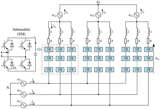
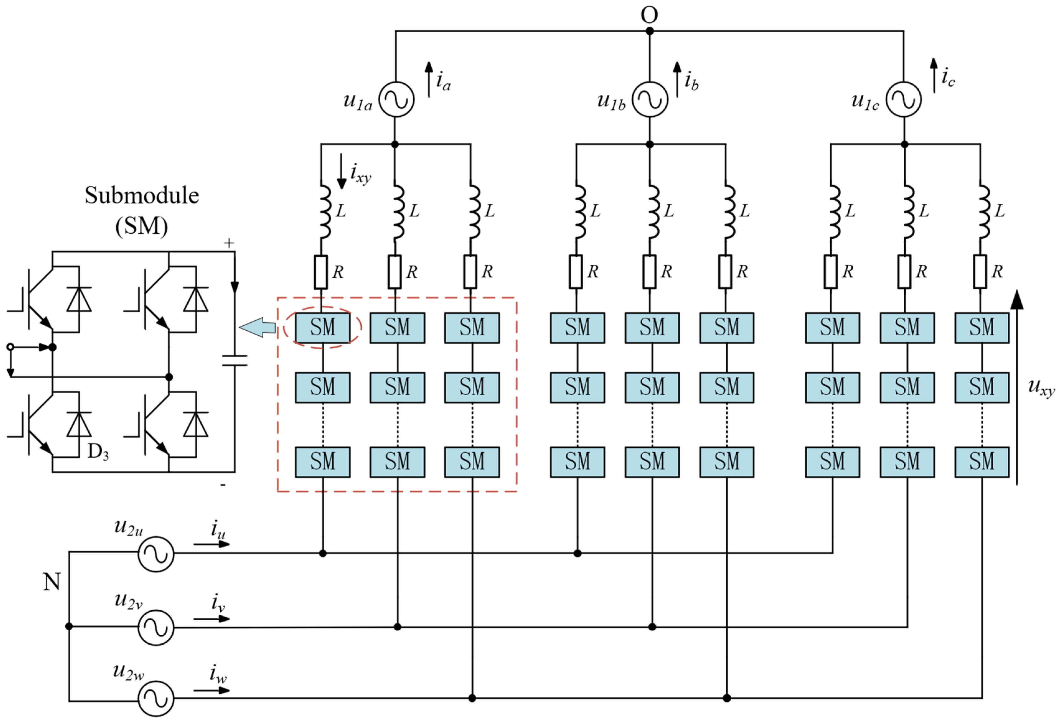
The main circuit of M3C adopts a nine-bridge-arm modular configuration, and each bridge arm consists of an equivalent inductor L, equivalent resistance R and n cascaded sub-modules. The schematic diagram of the M3C main circuit is shown in Figure 1 [21].
Figure 1.
Schematic diagram of main circuit configuration for M3C.
Define input phase voltage and phase current as u1x, i1x(x = a, b, c), output phase voltage and phase current as u2y, i2y(y = u, v, w), bridge-arm voltage and current as uxy, ixy, and bridge-arm voltage and current as uNO. Based on Kirchhoff’s Voltage Law, the third-order matrix voltage equation of M3C is established as Equation (1) [21]:
Phase current and bridge-arm current satisfy the relation in Equation (2):
Under three-phase balanced operation, the sum of three-phase currents at input and output terminals equals zero, as shown in Equation (3):
Since bridge-arm variables couple frequency components from both input and output ports, Clark transformation is implemented for converter decoupling, as shown in Equation (4):
Equation (4) indicates αβ components of bridge-arm voltage/current are only associated with input-side variables, while the zero-sequence component is dominated by output-side voltage. The decoupling formulas under the α-β coordinate system are derived as Equations (5) and (6):
To realize zero-steady-error steady-state control, Park transformation is applied to α-β decoupled equations. Let the angular frequency of the input power-frequency grid be ω1 and the output low-frequency angular frequency be ω2; transforming α-β variables into dual d-q rotating frames yields the d-q mathematical model of M3C expressed in Equations (7)–(10):
2.2. Outer-Loop Error Dynamic Equation and Lumped Disturbance Modeling of M3C
Dual closed-loop control is adopted for M3C, where outer-loop control is decoupled into the low-frequency input port and power-frequency output port. Capacitor energy balancing at the power-frequency side and high-precision power tracking at the low-frequency side essentially belong to nonlinear trajectory tracking problems. To facilitate robust controller design and theoretical proof of disturbance suppression capability, this section converts outer-loop trajectory tracking into state asymptotic convergence in error space and establishes a unified mathematical model for the system’s nonlinear lumped disturbance.
2.2.1. Establishment of Error Dynamic Equations
Under dual d-q rotating frames, the generalized reference command of the outer-loop state is denoted as xref. PLF_ref is the low-frequency active power reference in the low-frequency outer loop, and Udc_ref is the average sub-module capacitor voltage reference for the power-frequency outer loop, while x is the practical system state variable. The global tracking error is defined as e:
Considering unmodeled dynamics and parameter deviation, the single-input single-output affine nonlinear dynamics of the controlled plant is described by:
where u denotes the outer-loop control command; f(x) and g(x) represent nominal system mathematical functions; Δ(x,t) stands for unmodeled nonlinear uncertainties including switching dead zone, capacitance drift and various power losses.
Take the time derivative on both sides of Equation (11) and substitute into Equation (12) to obtain the error dynamic differential equation of the system:
2.2.2. Control Decoupling and Lumped Disturbance Extraction
It is difficult to accurately acquire the equivalent physical model parameters of the M3C under complex operating conditions. To reduce the dependence of the control system on the nominal model f(x), this paper adopts a feedforward-feedback decoupling control architecture and decomposes the control input u into:
where uffd denotes the feedforward control law calculated based on cross-port power conservation to maintain the fundamental power flow of the system; uc is the nonlinear feedback compensation law to be designed for suppressing the residual system error.
Substitute Equation (14) into Equation (13) and combine the non-ideal and unknown dynamic terms to yield:
Let the control input gain satisfy g(x) = b. According to the physical characteristics of M3C, b is a bounded positive constant. To facilitate the unified suppression of nonlinear disturbances and subsequent stability analysis of the designed controller, the term inside the square brackets in Equation (15) is defined as the lumped disturbance d(t) of the system:
Accordingly, the complex physical model of the original system is reconstructed into a standard error dynamic equation:
2.2.3. Disturbance Characteristic Analysis and Requirements of the Control Strategy
The error dynamic equation in Equation (17) provides a fundamental model to verify the suppression capability of the control system against the lumped disturbance d(t). During practical operation of the M3C, restricted by the inertia of large-capacity filtering links and continuous grid-side power fluctuations, the lumped disturbance generally varies slowly in a continuous time-varying manner. Accordingly, a reasonable assumption is made as follows: the lumped disturbance d(t) is twice continuously differentiable, and its second derivative is bounded by an unknown positive constant L, such that:
It should be emphasized that the assumption of a bounded second-order derivative for the lumped disturbance is mathematically reasonable and practically valid for offshore wind power applications. In practical M3C-based flexible low-frequency transmission systems, external disturbances and unmodeled dynamics propagate through cascaded multi-stage energy storage elements, including the massive rotational mechanical inertia of wind turbine generators, the large-capacity distributed capacitance of submarine cables, and the substantial bridge-arm inductances. These cascaded physical components inherently act as natural high-order low-pass filters, strictly limiting the slew rate and acceleration of state variations. Furthermore, in actual offshore wind farm operations, active power commands are strictly constrained by ramp-rate limiters rather than ideal theoretical step changes. Consequently, high-frequency discontinuous singular jumps are physically unachievable, ensuring that the physical lumped disturbances evolve in a sufficiently smooth manner, keeping their second-order derivatives strictly bounded within a defined operational envelope.
Restricted by the inertia of large-capacity filtering components in M3C and the continuous fluctuation characteristic of wind power, the system disturbance evolves as gradually varying dynamics with twice continuous differentiability. Conventional variable structure control strategies, such as first-order sliding mode and conventional second-order super-twisting sliding mode, can generally achieve zero-error tracking only for constant disturbances or disturbances with bounded first-order derivatives. When coping with time-varying dynamic disturbances whose second derivatives are bounded as described in Equation (18), steady-state dynamic errors are theoretically unavoidable with conventional second-order control schemes. Accordingly, to realize high-precision asymptotic stability at the origin under the above error dynamic model, the introduced control law is required to possess full compensation capacity for higher-order time-varying disturbances, which theoretically justifies the necessity of the proposed third-order structure.
2.3. Design of Third-Order Super-Twisting Sliding Mode Control Law
As indicated by the M3C error dynamic model Equation (17) derived in Section 2.2.2, the controller must be capable of rejecting the time-varying dynamic disturbance d(t) to achieve zero steady-state error tracking. To suppress high-frequency chattering caused by conventional first-order sliding mode in discrete digital control systems and overcome the limitations of the standard second-order super-twisting sliding mode under complicated dynamic disturbances, a third-order super-twisting sliding mode control law based on fractional powers and multiple integrals is constructed in this section for the simplified outer-loop structure of the M3C.
2.3.1. Selection of Sliding Surface
To match the outer-loop control architecture and avoid extra tracking delay, a pure error sliding surface is selected in this paper and directly defined as the global tracking error:
Differentiate Equation (19) with respect to time to obtain the error dynamic model consistent with Equation (17):
However, based on the homogeneity of nonlinear systems, the conventional second-order super-twisting sliding mode controller can only fully compensate for disturbances with bounded first derivatives. When dealing with the gradually varying lumped disturbance of the M3C system given in Equation (18), dynamic tracking errors are inevitable when using the second-order control law. Accordingly, a third-order super-twisting sliding mode controller is introduced in this paper.
2.3.2. Design of Super-Twisting Sliding Mode Control Law
For the error system described by Equation (20), a third-order super-twisting sliding mode control law is constructed in this paper as follows:
where k1, k2, and k3 denote positive sliding mode gains; ϑ(s) is a continuous function defined as:
where δ denotes the thickness of the sliding mode boundary layer and is a small positive constant.
The control law can be rewritten into an equivalent integral structure:
The proposed third-order super-twisting sliding mode control law possesses clear physical control significance in improving the transient response and steady-state accuracy of the system. The nonlinear proportional reaching term related to k1 provides a large nonlinear convergence gain when the system error is large (|s| > 1), accelerating the reaching motion of system states toward the sliding surface. When the error becomes small (|s| < 1), its equivalent feedback gain decreases smoothly and spontaneously, effectively restraining overshoot induced by high gain in conventional proportional-integral control. The nonlinear integral convergence term with k2 is adopted to raise the low-frequency gain near the equilibrium origin and suppress high-frequency transient fluctuations during the transition from transient to steady state, enabling high-precision asymptotic convergence of the system to the reference trajectory. The double-integral robust compensation term corresponding to k3 compensates for complicated time-varying disturbances, including internal parameter perturbations and varying external load disturbances, which theoretically guarantees zero steady-state error tracking against complex time-varying perturbations.
2.4. Disturbance Rejection Mechanism and Stability Analysis of the Closed-Loop System
Combining the third-order super-twisting control law derived in Section 2.3 with the outer-loop control system of the M3C yields a complex nonlinear closed-loop system involving high-order nonsmooth fractional-power terms and multiple integral components. To rigorously verify the effectiveness of the designed control law, a state-space transformation is first adopted to mathematically reveal the high-order complete decoupling mechanism against time-varying lumped disturbances. Afterwards, a generalized Lyapunov functional is constructed based on the nonlinear homogeneity theory to strictly prove the globally finite-time stable convergence of the closed-loop system.
2.4.1. Closed-Loop State-Space Reconstruction and High-Order Disturbance Decoupling Mechanism
Substituting the proposed third-order super-twisting sliding mode control law into the outer-loop error dynamic equation of the M3C yields the first-order evolution equation of the closed-loop system as follows:
Equation (24) reveals that the evolution of the error is restricted not only by the reaching law but also deeply algebraically coupled with the first-order internal integral state u1 of the controller and the external lumped disturbance d(t).
To eliminate such nonlinear coupling and extract the core anti-disturbance characteristics of the system, a high-order sliding mode canonical coordinate transformation is introduced to construct a set of new augmented state variables z1, z2, z3, which are defined as follows:
This coordinate transformation maps the external lumped disturbance together with its low-order derivatives into the augmented state space of the closed-loop system via the multiple-integral structure, thereby converting the external disturbance rejection problem into an internal stabilization problem of the system.
By taking the time derivative of each transformed state variable in Equation (25), the canonical differential equations for the outer-loop of the M3C are established as follows:
It can be observed from the reconstructed Equation (26) that the original lumped disturbance and its low-order derivatives acting on the M3C outer loop are completely eliminated in the first two closed-loop dynamics. This indicates that the external nonlinear dynamics are fully decoupled by the control system and equivalently transformed into the second-order derivative of the lumped disturbance within the high-order differential inclusion. Provided that the second-order derivative of the lumped disturbance is bounded, the designed controller can realize complete disturbance decoupling and effectively overcome the theoretical drawback of steady-state offset encountered by low-order controllers when coping with gradually varying dynamic disturbances.
2.4.2. Finite-Time Stability Analysis of Closed-Loop System
Based on the Lyapunov stability theorem, the practical finite-time stability of the closed-loop system over the entire state space is analyzed in this section.
To incorporate the continuous function ϑ(s) into the homogeneity analysis framework, an adaptive function α(s) is introduced and defined as follows:
Accordingly, the differential equations given by Equation (26) can be reconstructed into the following standard homogeneous canonical form with variable gains:
In accordance with the standard state-space representation of variable structure control systems, the generalized characteristic mapping error vector ζ is defined as follows:
A globally continuously differentiable and strongly positive definite quadratic homogeneous Lyapunov candidate functional V(z) is constructed as follows:
where P denotes a strictly positive definite real symmetric matrix.
Taking the time derivative of the Lyapunov functional along the trajectories of the canonical system yields:
Based on the closed-loop dynamics in Equation (28) and the definition of the characteristic vector ζ, the derivative of the characteristic vector can be expressed in a pseudo-linear matrix form . Substituting this relationship into the Lyapunov derivative gives:
To guarantee asymptotic convergence of the state vector, the matrix P must be explicitly designed to satisfy the continuous algebraic Lyapunov matrix equation:
where Q(α) is a time-varying positive definite weighting matrix constructed as involving the adaptive function α(s). Consequently, when the system states lie outside the boundary layer, the derivative of the Lyapunov functional is formulated as:
To rigorously derive the finite-time stability inequality from this quadratic form, the bounds of the Lyapunov functional are first established using the Rayleigh quotient principle:
where λmax(P) and λmin(P) denote the maximum and minimum eigenvalues of the symmetric positive definite matrix P, respectively. Equation (35) directly implies the relationship between the Euclidean norm of the characteristic vector and the functional:
Due to the fractional-power structure of the third-order super-twisting algorithm, the time derivative of the Lyapunov functional inherently contains a state-dependent homogeneous scaling factor, which is inversely proportional to the state variable |z1|1/3. By extracting this scaling factor, the derivative can be bounded as follows:
Based on the canonical state transformation, the state variable |z1| is bounded by the characteristic vector norm, satisfying for a positive constant C. Substituting this relationship yields the following decoupled bound:
where C is a positive constant determined by the boundary-layer and coordinate transformation parameters.
Substituting the Rayleigh bound of into the above inequality, the mathematically rigorous finite-time convergence condition is derived:
By defining the overall control damping constant as and setting the fractional exponent to ρ = 1/2, the closed-loop system strictly satisfies the following differential inequality for finite-time stability:
Since the exponent of the differential equation lies in the interval (0,1), the states of the closed-loop system will definitely converge into the boundary layer within finite time in accordance with the finite-time stability criterion for nonlinear systems.
When the system states enter the interior of the boundary layer, the continuous function degenerates into ϑ(z1) ≈ z1/δ. At this point, Equation (26) is transformed into the following form in the neighborhood of the origin:
It can be concluded from Equation (33) that the feedback term 1/δ endows the system with local stabilization capability since the boundary-layer thickness is set to a sufficiently small positive constant. As indicated by the foregoing Lyapunov convergence analysis, the system strictly satisfies the finite-time convergence condition on the boundary layer. In line with the invariance principle of nonlinear control theory, the inner region of the boundary layer forms a globally attractive positively invariant set in the state space. Subject to bounded perturbations induced by the second derivative of external lumped disturbances within this set, the system trajectories cannot cross backward across the boundary where .
In summary, the proposed control system satisfies finite-time stability under the practical constraint imposed by the continuous function ϑ(s).
2.5. Design of Outer-Loop Controller for M3C System
As the critical hub connecting low-frequency offshore wind farms and power-frequency onshore power grids, the M3C adopts a dual-terminal control architecture decoupled into power tracking control on the low-frequency side and steady-state control of capacitor voltage and reactive power on the power-frequency side. Conventional PI control and standard sliding mode control inevitably produce steady-state errors under large-power flow reversal or grid voltage sag, mainly due to their incapability of accurately eliminating multivariable coupling terms. Based on the high-order full decoupling principle and practical finite-time stability analysis derived in Section 2.4, a third-order super-twisting sliding mode control outer-loop controller for M3C is designed in the synchronous d-q rotating coordinate frame in this paper.
2.5.1. Design of Outer-Loop Control for Capacitor Voltage and Reactive Power at Power-Frequency Side
Considering the practical engineering characteristic that the power flow at the low-frequency side fluctuates frequently and transiently due to variable wind speeds in the low-frequency power transmission system, the grid-frequency input side is selected as the voltage support source to minimize the dynamic regulation burden of the low-frequency outer loop. Under the proposed control framework, the average submodule capacitor voltage is regulated in real time via the control law of the grid-frequency outer loop, while the low-frequency output side is dedicated to high-precision dynamic tracking of wind power.
The core objective of the grid-frequency outer loop is to maintain the average capacitor voltage of all submodules inside the M3C constant and supply the required reactive power Q1 in accordance with grid dispatching commands.
Define the capacitor voltage tracking error as svdc, whose expression is given as follows:
where denotes the reference value of the average capacitor voltage.
Since the submodule capacitor energy is accumulated by the integral of active power between the low-frequency side and grid-frequency side, the reference active power P2_ref of the low-frequency side is introduced as cross-port energy feedforward to realize macroscopic transient energy balance inside the M3C. Equal-amplitude synchronous rotating coordinate transformation and grid voltage space vector orientation are adopted at the grid-frequency side in the proposed control system to set the q-axis component of grid-frequency voltage to zero. On this basis, the instantaneous active power at the grid-frequency side is expressed as follows:
where ud1 is the d-axis component of the grid-frequency side grid voltage vector, and id1 denotes the d-axis component of the grid-frequency side current.
Combined with the disturbance rejection compensation characteristic of the third-order super-twisting sliding mode control law, the reference d-axis current id1_ref at the grid-frequency side is expressed as follows:
where usw_vdc stands for the compensation term of the third-order super-twisting sliding mode, which is formulated as follows:
Define the reactive power tracking error at the grid-frequency side as sq1, and its expression is given below:
where Q1_ref is the reference value of reactive power on the grid-frequency side, and Q1 is the actual reactive power of the grid-frequency side.
The reference q-axis current iq1_ref of the grid-frequency side is expressed as follows:
2.5.2. Design of Outer-Loop Control for Active and Reactive Power at the Low-Frequency Side
The primary task of the low-frequency outer loop is to achieve zero-steady-error asymptotic tracking of the active power command P2_ref and reactive power command Q2_ref issued by the offshore wind farm.
Define the global active power tracking error at the low-frequency side as sp2, whose expression is shown as follows:
where P2 represents the actual active power of the low-frequency side.
The reference d-axis current id2_ref of the low-frequency side is given as follows:
Define the reactive power tracking error at the low-frequency side as sq2, and its expression is as follows:
where Q2_ref denotes the reference value of reactive power on the low-frequency side, and Q2 is the measured reactive power of the low-frequency side.
The reference q-axis current iq2_ref for the low-frequency side is expressed as follows:
The reference command currents synthesized by the above outer loops are directly sent to the inner-loop regulator of the M3C. In offshore wind grid-connected applications, the M3C is frequently subjected to complicated transient disturbances such as stepwise abrupt load power variation and asymmetrical grid voltage sags. By introducing the nonlinear integral state of the super-twisting sliding mode, the proposed control framework realizes real-time estimation and feedforward compensation of lumped system disturbances, which remarkably improves the dynamic tracking speed and robustness against severe disturbances. In addition, benefiting from the continuous control law design, the proposed scheme effectively eliminates the inherent high-frequency chattering problem existing in conventional sliding mode control.
3. Simulation Results and Analysis
To verify the effectiveness and superiority of the proposed control strategy, an M3C flexible low-frequency transmission system model is established in MATLAB R2023b/Simulink. Furthermore, to highlight the advantages of the proposed third-order super-twisting sliding mode control in suppressing high-order internal dynamics, a comparative simulation is conducted alongside the standard super-twisting sliding mode control under identical operating conditions. The main parameters of the simulation model are listed in Table 1.
Table 1.
Main parameters of the simulation model.
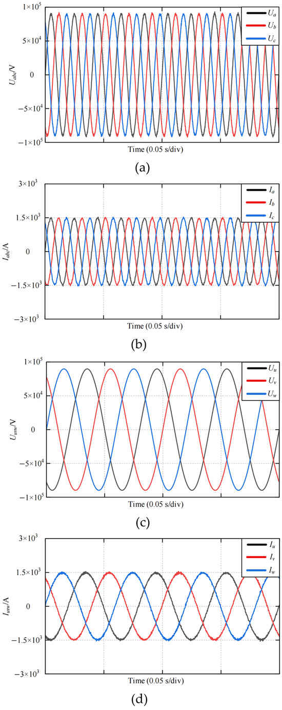
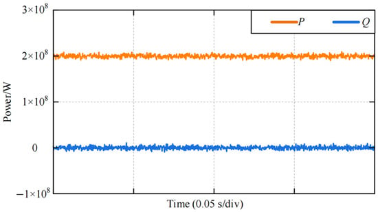
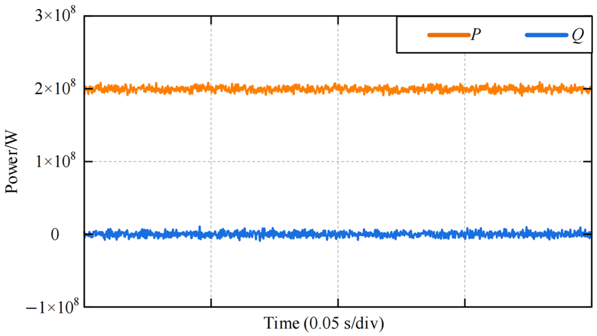
Figure 2 illustrates the input and output voltage and current waveforms of the M3C system under steady-state operation using the proposed TOSMC. It can be observed from Figure 2 that the waveforms exhibit favorable quality and maintain strict three-phase symmetry. Figure 3 presents the steady-state power waveforms, where the active power precisely tracks the reference value of 200 MW. The combined results in Figure 2 and Figure 3 confirm that the M3C system operates reliably, verifying the steady-state effectiveness of the proposed control strategy.
Figure 2.
Simulation waveforms of voltage and current for the M3C system with outer-loop TOSMC under steady-state operation. (a) Input voltage; (b) input current; (c) output voltage; (d) output current.
Figure 3.
Simulation waveforms of active and reactive power of the M3C system with outer-loop TOSMC under steady-state operation.
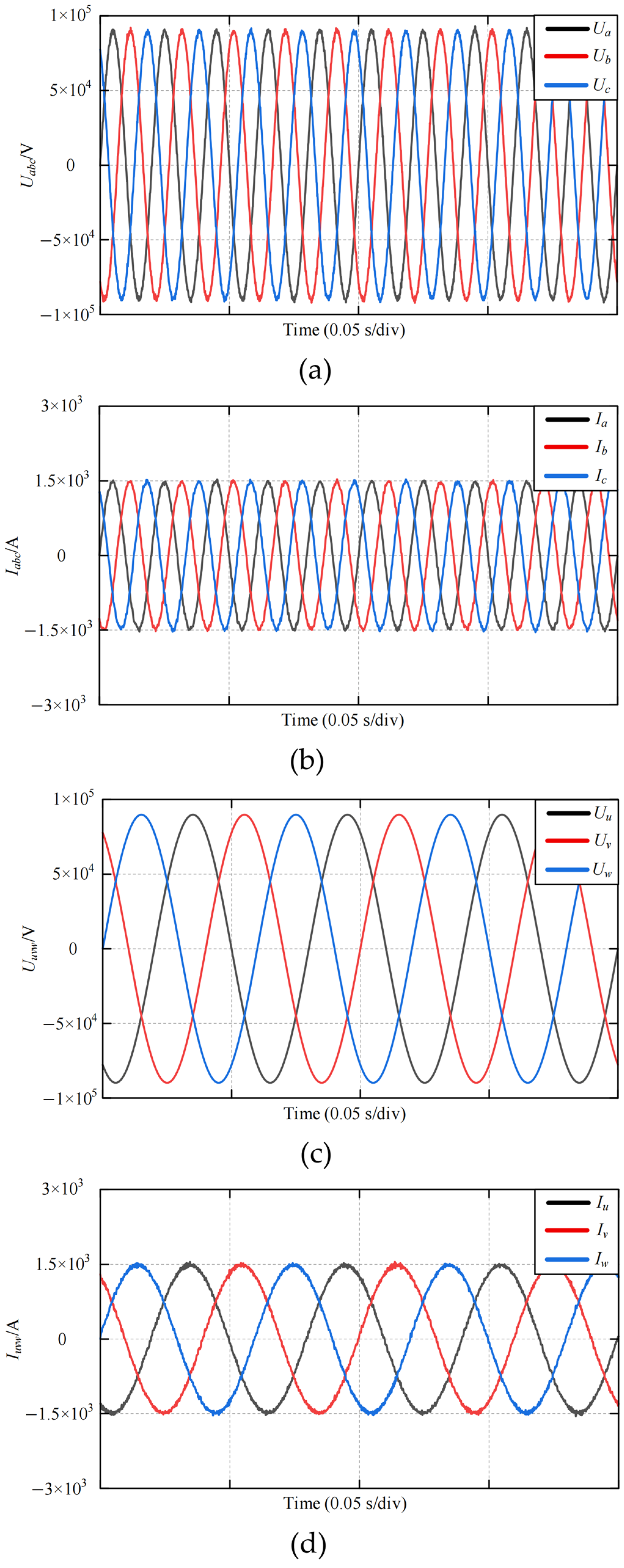
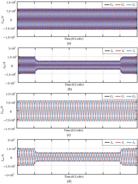
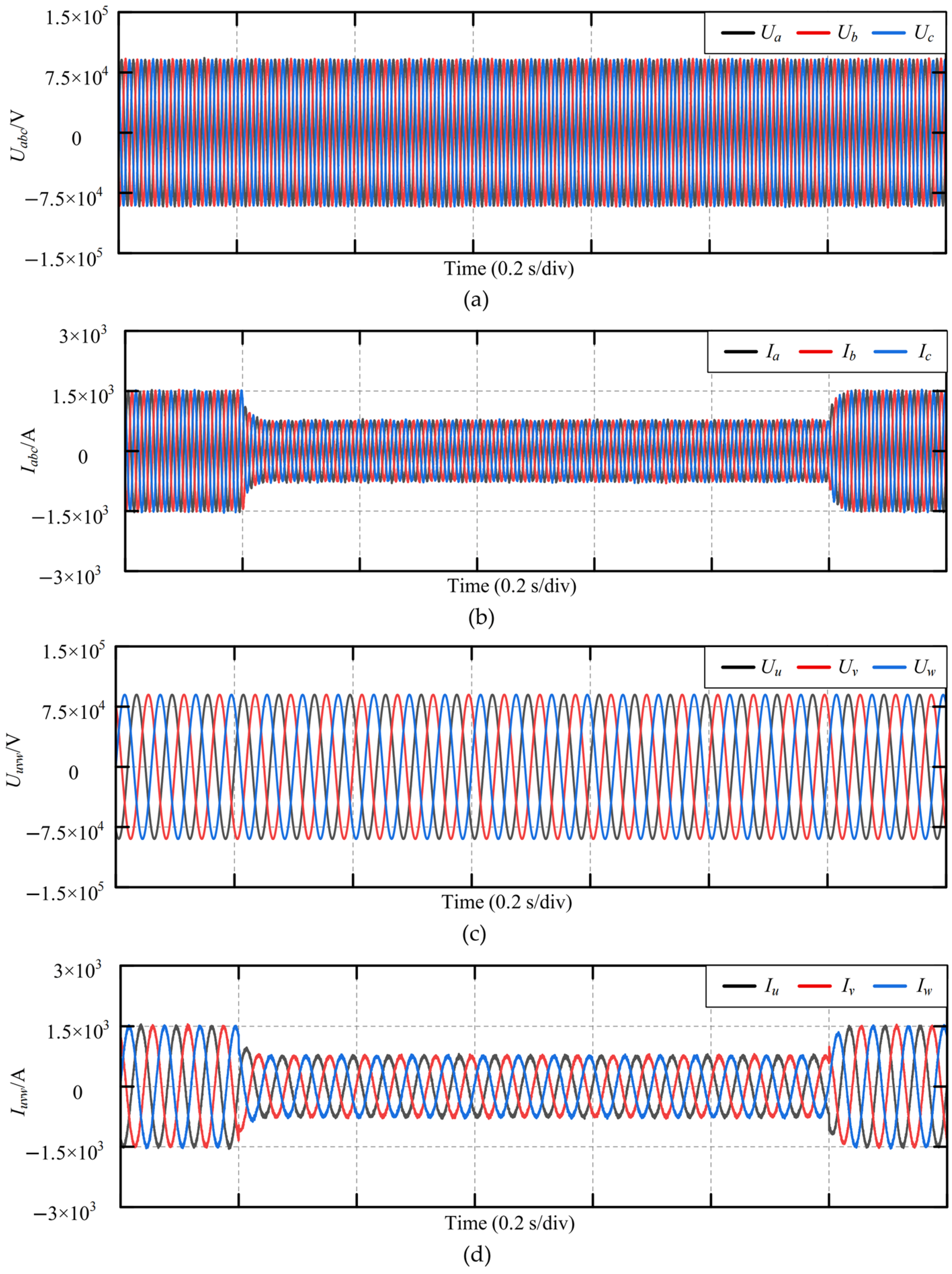
To evaluate the dynamic performance and superiority of the proposed method, comparative simulations between the proposed TOSMC and the STSMC are conducted. The system is subjected to a transient condition where the active power reference steps down from 200 MW to 100 MW, and then steps back up to 200 MW after 1 s. Figure 4 shows the corresponding input and output voltage and current waveforms under the TOSMC strategy. As can be seen from Figure 4, both input and output currents converge rapidly to the new steady state and promptly recover their three-phase balance following the active power step changes.
Figure 4.
Simulation waveforms of voltage and current for the M3C system with outer-loop TOSMC under active power step change. (a) Input voltage; (b) input current; (c) output voltage; (d) output current.
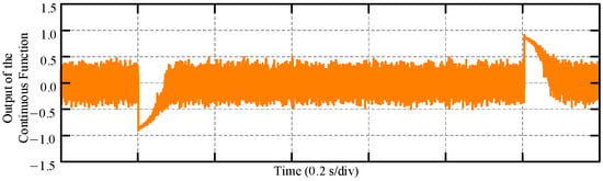
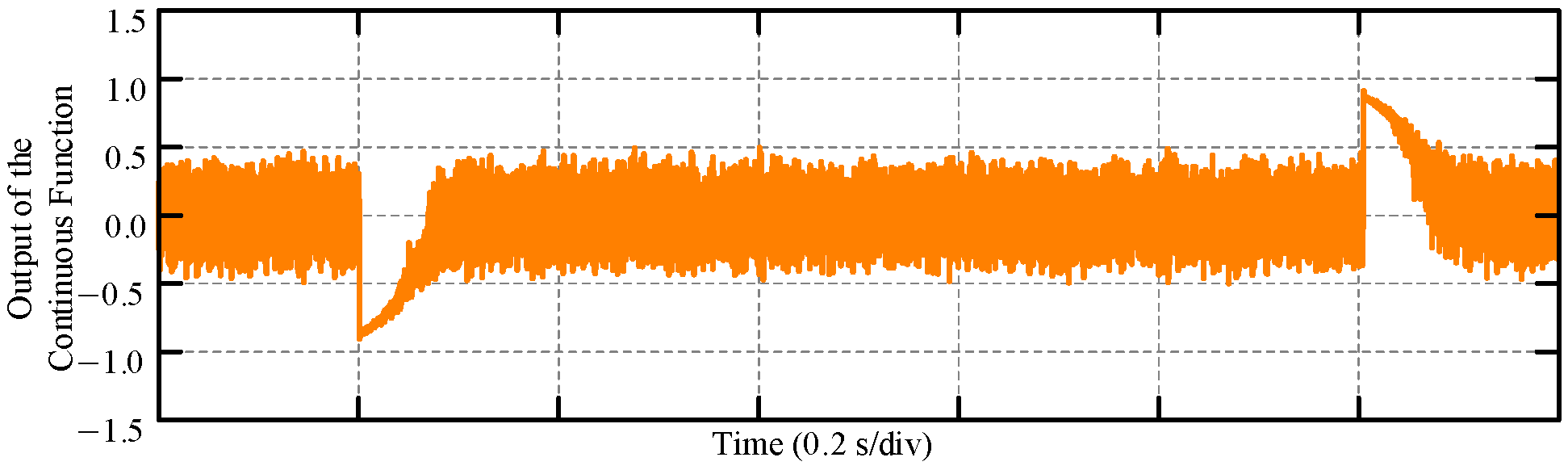
Figure 5 depicts the output waveform of the continuous boundary layer function ϑ(s) implemented in the proposed TOSMC. As shown in Figure 5, under steady-state conditions where tracking errors are minimal, the output magnitude of this function remains low, which effectively mitigates the inherent sliding mode chattering. Conversely, during dynamic transients with significant tracking errors, the output increases adaptively to accelerate error convergence, thereby guaranteeing a fast dynamic response.
Figure 5.
Output waveform of the continuous boundary layer function in TOSMC under active power step variation.
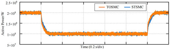
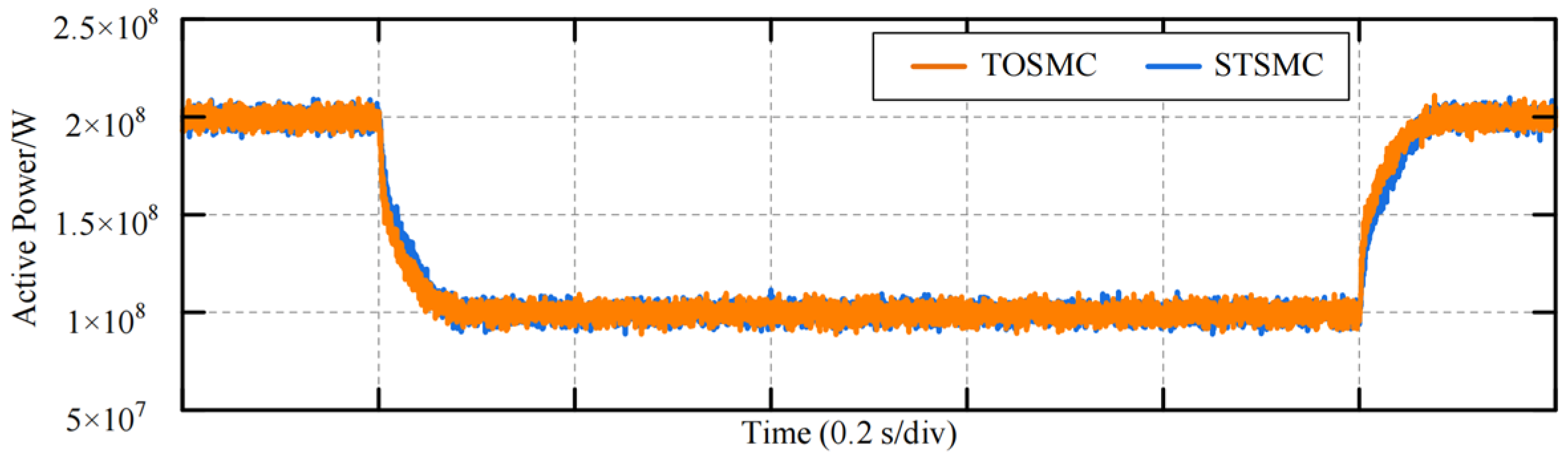
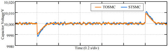
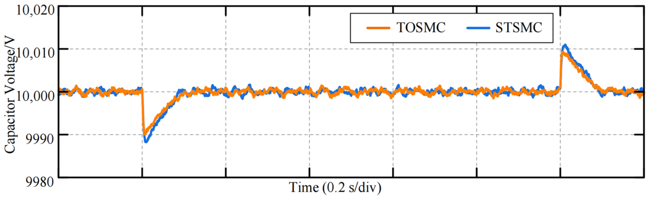
Figure 6 and Figure 7 illustrate the active power and total average capacitor voltage waveforms of the M3C system under the proposed TOSMC and the STSMC presented in [22] during reference active power step variations. As depicted in Figure 6, during the active power step changes, both the STSMC and the proposed TOSMC track the power reference without transient overshoot, with a settling time of approximately 0.1 s. Furthermore, in terms of the overall tracking precision throughout the entire process, the proposed TOSMC reduces the root mean square error (RMSE) of the active power from 13 MW under the STSMC to 10.78 MW. This quantitative difference verifies that the multi-integral structure in the TOSMC more effectively minimizes transient tracking deviations and suppresses high-frequency chattering. Therefore, while both sliding mode strategies ensure accurate macroscopic power tracking, the TOSMC further minimizes residual dynamic fluctuations for a smoother overall performance.
Figure 6.
Comparative simulation waveforms of active power for M3C system under active power step variation.
Figure 7.
Comparison of simulated total average capacitor voltage waveforms of M3C under active power step variation.
As illustrated in Figure 7, during the step drop and subsequent restoration of the reference active power, the maximum amplitude fluctuations of the total average capacitor voltage for the M3C system under the standard STSMC reach 11.73 V and 10.98 V, respectively. By contrast, the corresponding maximum voltage fluctuations are restricted to only 9.94 V and 9.36 V when the proposed TOSMC is adopted, representing an approximate 15% reduction in transient amplitude fluctuation. This significant improvement highlights the superiority of the multi-integral robust compensation structure in the TOSMC. While the standard STSMC struggles to completely reject the complex, high-order internal cross-coupling disturbances inherent in the M3C topology, the proposed TOSMC effectively observes and suppresses these non-vanishing dynamics, thereby ensuring a much smoother internal energy balancing process.
In conclusion, the comparative simulation results verify that compared with the standard STSMC, the proposed TOSMC strategy maintains equivalently rapid and robust macroscopic power tracking performance. Furthermore, it achieves a superior internal anti-disturbance capability by effectively suppressing complex, high-order cross-coupling dynamics, thereby providing a smoother and more reliable energy balancing process for the M3C system under transient conditions.
4. Conclusions
To address the multi-variable strong coupling and complex time-varying disturbances in M3C-based flexible low-frequency transmission systems, this paper proposes a dual-terminal decoupling control strategy based on a third-order super-twisting sliding mode controller. By incorporating a cross-port power reference feedforward mechanism and a multi-integral robust compensation structure, the proposed method achieves precise macroscopic power flow regulation and real-time suppression of complex high-order internal dynamics. Comparative simulation results demonstrate that, compared with the standard second-order STSMC, the proposed TOSMC maintains an equivalently rapid and robust macroscopic active power tracking performance with strictly zero transient overshoot. More importantly, at the internal microscopic level, the proposed method effectively reduces the transient amplitude fluctuation of the average sub-module capacitor voltage by approximately 15%. This confirms that the proposed control strategy ensures a smoother internal energy balancing process and superior anti-disturbance capability without sacrificing dynamic response speed.
Despite the excellent dynamic and steady-state performance demonstrated in the theoretical analysis and simulation, the proposed control strategy has certain minor limitations. The introduction of the multi-integral structure and the third-order sliding mode surface inevitably increases the number of control parameters, which may make the manual parameter tuning process relatively complex for practical engineering deployment. Therefore, future research will focus on integrating intelligent parameter optimization algorithms to simplify the controller design and reduce tuning reliance. Furthermore, hardware-in-the-loop (HIL) experiments and investigations into the M3C ride-through control under asymmetric grid fault conditions will be conducted to further evaluate the practical reliability of the proposed method in real-world applications.
Author Contributions
Conceptualization, Z.L.; Methodology, Y.L.; Validation, Y.Y.; Resources, J.Y.; Writing—Original Draft, C.D.; Writing—Review and Editing, X.N.; Writing—Review and Editing, J.L. All authors have read and agreed to the published version of the manuscript.
Funding
This research was funded by the Science and Technology Project of State Grid Zhejiang Electric Power Co., Ltd. (B311DS25Z021).
Data Availability Statement
The original contributions presented in this study are included in the article. Further inquiries can be directed to the corresponding author.
Conflicts of Interest
Authors Ziming Li, Yi Lu, Yanxia Yao, Jiachuan You, Chao Ding and Xiaojun Ni were employed by the company State Grid Zhejiang Electric Power Co., Ltd. Electric Power Research Institute. The remaining author declares no conflicts of interest. The funders had no role in the design of the study; in the collection, analyses, or interpretation of data; in the writing of the manuscript; or in the decision to publish the results.
References
- Chen, W.J.; Zhao, G.L. Key technologies and equipment of new power system dominated by new energy. Glob. Energy Interconnect. 2022, 5, 1. [Google Scholar]
- Huang, Y.; Tao, Y.Z.; Kong, Z.D. Techno-economic analysis of flexible low-frequency transmission system for offshore wind power. Power Syst. Technol. 2024, 48, 4865–4875. [Google Scholar]
- Liu, Z.Q.; Liu, Y.; Hou, J.M. Economic analysis of energy delivery for energy island centered on deep-sea offshore wind power. Electr. Power 2024, 57, 94–102. [Google Scholar]
- Feng, S.; Wei, C.F.; Lei, J.X. Hybrid modeling and control of modular multilevel matrix converter for frequency-divided offshore wind power system. Proc. Chin. Soc. Electr. Eng. 2022, 42, 1546–1558. [Google Scholar] [CrossRef]
- Lu, L.W.; Wu, X.D.; Zhou, Q.; Dong, Y.; Qiu, D.; Pan, L. Non-disturbance grid-connection control strategy for two-terminal flexible low-frequency transmission system. Electr. Power Eng. Technol. 2022, 41, 31–39. [Google Scholar]
- Zhu, D.; Pei, Z.; Liu, C.; Wang, J.; Kong, D.; Liu, C.; Sun, Y.; Guo, D.; Heldwein, M.L. Isolated Modular Multilevel Matrix Converter (I-M3C) Based Novel Solid-State Transformer (SST) with Low-Frequency Medium-Voltage AC Port. IEEE Trans. Power Electron. 2024, 39, 12397–12410. [Google Scholar] [CrossRef] [Scilit]
- Zhang, Z.R.; Jin, Y.Q.; Xu, Z. Modeling and control of modular multilevel matrix converter for low-frequency AC transmission. Energies 2023, 16, 3474. [Google Scholar] [CrossRef] [Scilit]
- Li, J.Y.; Han, Y.; Wang, J.J. Control strategy of M3C system applied to AC/AC conversion. Electr. Drive 2025, 55, 13–19. [Google Scholar] [CrossRef]
- Wu, Z.; Liu, J.; Yang, X.M.; Ji, Y.; Xu, X.Y.; Yao, W.X. Capacitor voltage balancing strategy of modular multilevel matrix converter. J. Power Supply 2022, 20, 108–114. [Google Scholar] [CrossRef]
- Lu, Y.; Wu, X.D.; Lei, J.X.; Sun, X.; Gu, Y.; Wei, C. Control strategy of modular multilevel matrix converter under unbalanced grid condition. Electr. Power Eng. Technol. 2023, 42, 195–205. [Google Scholar] [CrossRef]
- Cuzmar, R.H.; Mora, A.; Pereda, J.; Aguilera, R.P.; Poblete, P.; Neira, S. Computationally Efficient MPC for Modular Multilevel Matrix Converters Operating with Fixed Switching Frequency. IEEE Open J. Ind. Electron. Soc. 2023, 4, 748–761. [Google Scholar] [CrossRef] [Scilit]
- Chen, P.W.; Li, H.J.; Chen, J.; Liu, Z.Y.; Xu, Y.F. High-frequency oscillation characteristic analysis and suppression strategy of offshore wind low-frequency outgoing system based on M3C. Trans. China Electrotech. Soc. 2026, 41, 1543–1557+1588. [Google Scholar] [CrossRef]
- Castillo-Sierra, R.; Venkataramanan, G.; Ramirez, D. Reactive Component Reduction in Modular Multilevel Matrix Converters through Iterative Design-Simulation Cycles. In Proceedings of the 2022 IEEE Energy Conversion Congress and Exposition (ECCE), Detroit, MI, USA, 1–8 October 2022. [Google Scholar]
- Zheng, T.; Song, W.N.; Lv, W.X. Asymmetric fault ride-through control strategy of low-frequency transmission system based on M3C. Power Syst. Prot. Control 2023, 51, 107–117. [Google Scholar] [CrossRef]
- Zheng, T.; Kang, H.; Song, W.N. M3C capacitor voltage balancing control strategy enabling asymmetric fault ride-through of low-frequency transmission system. Power Syst. Prot. Control 2023, 51, 130–140. [Google Scholar] [CrossRef]
- Wu, X.D.; Li, J.C.; Dong, Y.L. Comprehensive decoupling control strategy of modular multilevel matrix converter for low-frequency offshore wind power delivery. Proc. Chin. Soc. Electr. Eng. 2023, 43, 3177–3191. [Google Scholar] [CrossRef]
- Cheng, Q.M.; Zhang, L.; Zhang, L. Common-mode voltage injection fault ride-through control strategy for M3C in low-frequency transmission system. South. Power Syst. Technol. 2026, 20, 1–9+70. [Google Scholar] [CrossRef]
- Liu, L.; Lu, H.D.; Ding, S.H. High-Order Sliding Mode Control Design Subject to Unknown Nonvanishing Uncertainties. IEEE Trans. Cybern. 2026, 56, 4634–4644. [Google Scholar] [CrossRef] [Scilit] [PubMed]
- Ding, H.; Xu, J.R.; Yuan, J.; Li, L.X.; Zhang, Z.B. A Robustness-Enhanced Dual-Loop Control Strategy Based on SMC for Vienna Rectifier. IEEE Trans. Ind. Electron. 2026, 73, 11077–11089. [Google Scholar] [CrossRef] [Scilit]
- Dash, J.R.; Raj, R.; Agarwal, P. Sliding Mode Control-Based Harmonic Suppression and Switching Loss Reduction in Modular Multilevel Converters. IEEE Trans. Ind. Electron. 2026, 73, 5055–5066. [Google Scholar] [CrossRef] [Scilit]
- Yang, X.H.; Zhang, N.; Li, X.Q. Research on Global Fast Terminal Sliding Mode Control for M3C in Offshore Wind Power Systems. J. Power Supply 2025, 1–14. Available online: https://link.cnki.net/urlid/12.1420.tm.20251225.1823.010 (accessed on 22 September 2026).
- Yang, X.H.; Wu, F.Y.; Zhang, S.J. Optimization of M3C Control Strategy Based on Super-Twisting Sliding Mode Control. J. Power Supply 2026, 1–12. Available online: https://link.cnki.net/urlid/12.1420.TM.20260328.1352.004 (accessed on 22 September 2026).

Disclaimer/Publisher’s Note: The statements, opinions and data contained in all publications are solely those of the individual author(s) and contributor(s) and not of MDPI and/or the editor(s). MDPI and/or the editor(s) disclaim responsibility for any injury to people or property resulting from any ideas, methods, instructions or products referred to in the content. |
© 2026 by the authors. Licensee MDPI, Basel, Switzerland. This article is an open access article distributed under the terms and conditions of the Creative Commons Attribution (CC BY) license.